EP2969345B1 - Détection des paramètres de procédé à l'aide des caractéristiques électriques de la flamme dans le traitement thermique oxy-combustible - Google Patents
Détection des paramètres de procédé à l'aide des caractéristiques électriques de la flamme dans le traitement thermique oxy-combustible Download PDFInfo
- Publication number
- EP2969345B1 EP2969345B1 EP14767439.4A EP14767439A EP2969345B1 EP 2969345 B1 EP2969345 B1 EP 2969345B1 EP 14767439 A EP14767439 A EP 14767439A EP 2969345 B1 EP2969345 B1 EP 2969345B1
- Authority
- EP
- European Patent Office
- Prior art keywords
- torch
- current
- slope
- oxy
- work piece
- Prior art date
- Legal status (The legal status is an assumption and is not a legal conclusion. Google has not performed a legal analysis and makes no representation as to the accuracy of the status listed.)
- Active
Links
Images





Classifications
-
- G—PHYSICS
- G05—CONTROLLING; REGULATING
- G05B—CONTROL OR REGULATING SYSTEMS IN GENERAL; FUNCTIONAL ELEMENTS OF SUCH SYSTEMS; MONITORING OR TESTING ARRANGEMENTS FOR SUCH SYSTEMS OR ELEMENTS
- G05B19/00—Program-control systems
- G05B19/02—Program-control systems electric
- G05B19/18—Numerical control [NC], i.e. automatically operating machines, in particular machine tools, e.g. in a manufacturing environment, so as to execute positioning, movement or co-ordinated operations by means of program data in numerical form
- G05B19/402—Numerical control [NC], i.e. automatically operating machines, in particular machine tools, e.g. in a manufacturing environment, so as to execute positioning, movement or co-ordinated operations by means of program data in numerical form characterised by control arrangements for positioning, e.g. centring a tool relative to a hole in the workpiece, additional detection means to correct position
-
- B—PERFORMING OPERATIONS; TRANSPORTING
- B23—MACHINE TOOLS; METAL-WORKING NOT OTHERWISE PROVIDED FOR
- B23K—SOLDERING OR UNSOLDERING; WELDING; CLADDING OR PLATING BY SOLDERING OR WELDING; CUTTING BY APPLYING HEAT LOCALLY, e.g. FLAME CUTTING; WORKING BY LASER BEAM
- B23K5/00—Gas flame welding
-
- B—PERFORMING OPERATIONS; TRANSPORTING
- B23—MACHINE TOOLS; METAL-WORKING NOT OTHERWISE PROVIDED FOR
- B23K—SOLDERING OR UNSOLDERING; WELDING; CLADDING OR PLATING BY SOLDERING OR WELDING; CUTTING BY APPLYING HEAT LOCALLY, e.g. FLAME CUTTING; WORKING BY LASER BEAM
- B23K5/00—Gas flame welding
- B23K5/22—Auxiliary equipment, e.g. backings, guides
-
- B—PERFORMING OPERATIONS; TRANSPORTING
- B23—MACHINE TOOLS; METAL-WORKING NOT OTHERWISE PROVIDED FOR
- B23K—SOLDERING OR UNSOLDERING; WELDING; CLADDING OR PLATING BY SOLDERING OR WELDING; CUTTING BY APPLYING HEAT LOCALLY, e.g. FLAME CUTTING; WORKING BY LASER BEAM
- B23K7/00—Cutting, scarfing, or desurfacing by applying flames
- B23K7/10—Auxiliary devices, e.g. for guiding or supporting the torch
-
- B—PERFORMING OPERATIONS; TRANSPORTING
- B23—MACHINE TOOLS; METAL-WORKING NOT OTHERWISE PROVIDED FOR
- B23K—SOLDERING OR UNSOLDERING; WELDING; CLADDING OR PLATING BY SOLDERING OR WELDING; CUTTING BY APPLYING HEAT LOCALLY, e.g. FLAME CUTTING; WORKING BY LASER BEAM
- B23K7/00—Cutting, scarfing, or desurfacing by applying flames
- B23K7/10—Auxiliary devices, e.g. for guiding or supporting the torch
- B23K7/102—Auxiliary devices, e.g. for guiding or supporting the torch for controlling the spatial relationship between the workpieces and the gas torch
-
- G—PHYSICS
- G05—CONTROLLING; REGULATING
- G05B—CONTROL OR REGULATING SYSTEMS IN GENERAL; FUNCTIONAL ELEMENTS OF SUCH SYSTEMS; MONITORING OR TESTING ARRANGEMENTS FOR SUCH SYSTEMS OR ELEMENTS
- G05B15/00—Systems controlled by a computer
- G05B15/02—Systems controlled by a computer electric
-
- G—PHYSICS
- G05—CONTROLLING; REGULATING
- G05F—SYSTEMS FOR REGULATING ELECTRIC OR MAGNETIC VARIABLES
- G05F1/00—Automatic systems in which deviations of an electric quantity from one or more predetermined values are detected at the output of the system and fed back to a device within the system to restore the detected quantity to its predetermined value or values, i.e. retroactive systems
- G05F1/10—Regulating voltage or current
- G05F1/625—Regulating voltage or current wherein it is irrelevant whether the variable actually regulated is AC or DC
-
- G—PHYSICS
- G05—CONTROLLING; REGULATING
- G05B—CONTROL OR REGULATING SYSTEMS IN GENERAL; FUNCTIONAL ELEMENTS OF SUCH SYSTEMS; MONITORING OR TESTING ARRANGEMENTS FOR SUCH SYSTEMS OR ELEMENTS
- G05B2219/00—Program-control systems
- G05B2219/30—Nc systems
- G05B2219/41—Servomotor, servo controller till figures
- G05B2219/41383—Observe current, voltage, derive position
Definitions
- Embodiments of the present invention relate generally to the field of oxy fuel thermal processing equipment, and more particularly to system that can obtain parameters associated with a thermal cutting or welding process using electrical characteristics of the torch flame an oxy fuel thermal processing equipment.
- Modern automated gas cutting torches are commonly equipped with features such as automatic ignition, automatic standoff control, kindling temperature detection, ignition and blowout detection, and neutral flame detection.
- Each of these features can be implemented using actuation and sensing mechanisms that should be reliable, economical, and resistant to the harsh operating environments created when cutting is performed (e.g. high heat, abrasive debris, particulate deposition etc.).
- U.S. Patent Number 4,328,049 forms the basis for the preambles of claims 1 and 7 and discloses a torch height sensing apparatus for generating information representative of the spacing between a cutting torch and an associated workpiece.
- U.S. Patent Number 5,470,047 discloses a flame sensor for use in a gas cutting apparatus, where the flame sensor is capable of directly measuring an electrical current flowing through a flame formed between the torch and the workpiece.
- German Patent Publication Number 102009033556A1 discloses a method for determining a distance variable characterizing the distance between an oxy-fuel burner device and a workpiece.
- Various embodiments of the present disclosure are generally directed to an automated oxy-fuel thermal processing system and a method of operating the same.
- the system is an oxy-fuel cutting system.
- the system is an oxy-fuel welding system.
- an oxy-fuel thermal processing system comprising a torch having a first surface and a workpiece having a second surface.
- a current driver is coupled between the first and second surfaces for driving a current between the first and second surfaces, the first and second surfaces exposed to a flame of the torch.
- a voltage sensor is coupled between the first and second surfaces for sensing a voltage response to a driven current supplied by the current driver.
- a microprocessor is in communication with the current driver and the voltage sensor and is configured to receive information of the driven current and sensed voltage response.
- the microprocessor is further configured to calculate a slope in the linear regime of the characteristic current voltage (I-V) relationship of the driven current and the sensed voltage response associated with a thermal process of the oxy-fuel thermal processing system, and to determine if the slope is within a predetermined range. When it is determined that the slope is outside the predetermined range, the microprocessor is configured to instruct adjustment of a gas mixture associated with the thermal process.
- I-V characteristic current voltage
- a method for controlling an oxy-fuel thermal processing process applies a current between first and second surfaces while the first and second surfaces are exposed to a flame of a torch, where the first surface is a surface of the torch and the second surface is a surface of a work piece.
- the method senses a voltage between the first surface and the second surface generated in response to the applied current, and receives information of the applied current and sensed voltage.
- a slope in the linear regime of the characteristic current voltage (I-V) relationship of the applied current and the sensed voltage associated with a thermal process of the oxy-fuel thermal processing system is calculated.
- the method determines if the slope is within a predetermined range, and when it is determined that the slope is outside the predetermined range, instructs adjustment of a gas mixture associated with the thermal process.
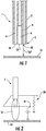
- an oxy-fuel cutting torch 1 can comprise a long cylinder 2 with internal passages 4, 6 configured to deliver gaseous fuel (e.g., acetylene, propane, or the like) and oxygen, respectively, to a nozzle 8, mounted at the cylinder's bottom.
- gaseous fuel e.g., acetylene, propane, or the like
- the nozzle 8 can issue a premixed combustible mixture from an array of ports 10 arranged around a central port 12 from which pure oxygen is issued.
- the torch 1 is positioned a distance above a work piece 14.
- the torch 1 may be operating with a stable flame 16 ( FIG. 2 ) oriented downward at the work piece 14. At this point oxygen is not supplied through the central port 12. Rather, the flame 16 may be used to heat the work piece 14 until it is hot enough that the material will burn in an oxygen atmosphere.
- the critical temperature needed for a cut to successfully begin is referred to as the "kindling temperature.”
- the work piece 14 reaches its kindling temperature, oxygen is supplied via the central port 12. If the work piece 14 is sufficiently hot, it will ignite and the flow of oxygen will pierce the work piece.
- the torch 1 can then be moved along a desired cut path to cut the work piece into a desired shape.
- the material in front of the flame is relatively cool, and thus it must be brought up to the kindling temperature in order to enable it to be cut by the flame.
- the process relies on the preheat flame, but particularly relies on the heat released from the cut itself.
- the torch 1 is advanced too quickly the heat released from the cut may not have sufficient time to conduct into the surrounding plate, and the temperature of the surface inside the advancing cut will fall. If the temperature drops too low then combustion may stop, and the preheat process will need to be repeated to restart the cut.
- the torch 1 Before the process is begun, the torch 1 is ignited and the flow of fuel and oxygen brought into desired proportions. The torch 1 is then brought to a predetermined height above the work piece and allowed to bring the material to its kindling temperature. The specific height and the timing of the process can be important to the successful initiation of a cut.
- cutting systems often include automated and/or manual adjustment mechanisms for moving the torch 1 in two horizontal axes (x-y) in order to generate a cut path on a work piece such as a flat plate.
- the adjustment mechanism may also be configured for adjusting the height of the torch 1 relative to the work piece.
- Such adjustment mechanisms are known in the art, and thus will not be described in detail herein. It will be appreciated that the disclosed system not limited to use with such mechanisms, there are many potential embodiments that include them.
- the oxy-fuel cutting process can include a series of operations including a number of steps that rely on feedback, either from a human operator or from an appropriately robust suite of sensors and controls.
- feedback can be desirable to facilitate adjusting the torch's fuel-oxygen mixture to achieve a desired "neutral flame.”
- sensor feedback indicates the work piece 14 temperature is not determinable (e.g. , due to sensor error)
- the operator must visually observe the glow of the work piece, or an automated system must be programmed to wait for an additional period of time to ensure that the work piece has achieved its kindling temperature so that cutting will successfully start.
- a standoff distance "SD" between the torch 1 and the work piece 14 depends on feedback control since the standoff can be on the order of 25.4 mm (1 inch) or less, and the torch may be positioned many feet from the operator making visual observation difficult or inconvenient.
- an electrical potential applied between two surfaces that are otherwise electrically isolated will result in a flow of current through the torch flame.
- This relationship can be measured using an arrangement such as that shown in FIG. 2 , illustrating the torch 1, the torch flame 16, a voltage source 18 and a shunt resistor 20.
- the voltage source 18 and shunt resistor 20 are but one possible embodiment, and that other arrangements can also be used.
- the description will proceed in relation to the use of two surfaces under test (e.g., the torch 1 and the work piece 14), other sensing surface configurations can also be used, and thus the disclosure is not so limited.
- the characteristic relationship between current and voltage can, but need not, pass through the origin.
- the two surfaces 1, 14 are made from different materials, or are at different temperatures, they will have a different affinity for electrons.
- This "floating potential” is the potential between two surfaces 1, 14 that is necessary to achieve zero current.
- the slope in the linear regime (II) is influenced by a number of characteristics including the flame temperature, the gas composition, and especially the distance between the surfaces.
- the slope of the I-V curve is an implicit measurement of the torch flame's electrical resistance in the path between the two surfaces 1, 14. As the surfaces 1, 14 approach each other (e.g., as the torch nozzle 8 is moved toward the work piece 14), or as the concentration of free radicals increases in the torch flame 16, the resistance of the torch flame drops detectably.
- the floating potential is influenced by the surface materials and temperature. Thus, for a given pair of surfaces 1, 14 if the temperature of one surface is known, then the floating potential can be assumed to be an indicator of the temperature of the other surface.
- the disclosed system and method exploits the electrical conductivity of the torch flame 16 to detect parameters important to the cutting process (e.g., torch offset, work piece temperature), while minimizing and/or eliminating the need for physical sensors and/or probes.
- parameters important to the cutting process e.g., torch offset, work piece temperature
- the disclosed system and method exploits the electrical conductivity of the torch flame 16 to detect parameters important to the cutting process (e.g., torch offset, work piece temperature), while minimizing and/or eliminating the need for physical sensors and/or probes.
- the electrical action can take the form of either an applied voltage or a driven current, with the resultant measurement being a measured current or measured voltage, respectively.
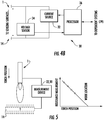
- FIG. 4A shows one example not covered by the present invention of a system 22 in which a voltage source 24 applies the electrical action, a current sensor 26 such as a shunt measures the current response, and a processor 28 collects a series of measurements and computes various parameters.
- a non-limiting exemplary list of directly measured parameters includes linear slope, floating potential, upper/lower saturation current, upper/lower saturation voltage and upper/lower saturation slope.
- a non-limiting exemplary list of derived parameters includes standoff distance "SD,” standoff error, flame mixture quality, cut speed error, imminent cut loss, successful ignition, and work piece temperature.
- FIG. 4B illustrates an embodiment of the disclosed system 30 in which current is driven in lieu of voltage.
- a current source 32 applies the electrical action
- a voltage sensor 34 measures the voltage response
- a processor 36 collects a series of measurements and computes various parameters, which have been previously identified.
- the imposition of an electrical action and measurement of an electrical response is used to interrogate the system's I-V characteristic, as will be described below, to obtain information about the operation of the system.
- One non-limiting exemplary method for measuring the floating potential is to force the current flow between the surfaces 1, 14 to zero. Once the voltage between the two surfaces 1, 14 stabilizes, it is taken as the floating potential. When driving voltage in lieu of current, the mean voltage signal can be adjusted until the mean current is zero. The mean voltage at zero mean current is then taken as the floating potential.
- One non-limiting exemplary method for measuring slope is by calculation, using two points in the linear regime. For accuracy, it may be desirable that the two points be as different in value as possible while remaining in the system's linear regime. Operation in the linear regime can be reasonably ensured if the two measurements are made near the floating potential.
- One non-limiting exemplary method for measuring floating potential and slope simultaneously is to apply an oscillating signal of some definite amplitude, such that the average current is zero.
- the average voltage will be the floating potential, and the ratio of the signal amplitudes will be the slope.
- the standoff height separating the torch 1 from the work piece 14 can be an important parameter in controlling an oxy-fuel cutting process.
- the exact location of the work piece surface may not necessarily known.
- the torch 1 and the work piece 14 may constitute the two surfaces under test, (i.e., as shown in FIGS. 4A and 4B ), eliminating the need for additional probes or sensors. It will be appreciated that any of a variety of surfaces of the torch 1 may be used as one of the surfaces under test, including the torch nozzle. A dedicated probe mounting surface (not shown) could also be mounted near the nozzle.
- a surface other than the work piece 14 could constitute the other surface under test.
- any electrically conductive component positioned near the flame 16 could be used.
- the torch 1 can be moved toward the work piece 14 in small predetermined increments. At each increment, a slope measurement can be recorded using the system 22, 30 of FIG . 4A or 4B .
- these compiled slope values are stored in memory 38 associated with the processor 28, 36. For example, the compiled slope values may be stored in a look up table in the memory 38.
- these measurements can form a trend tending to zero resistance for some position of the torch 1 with respect to the work piece 14. That extrapolated location may represent the position of the torch 1 where the tip of the nozzle 8 is touching the work piece 14.
- that value can be used to determine the position of the work piece 14, or more particularly it can be correlated to a specific standoff distance "SD" ( FIG. 1 ) between the torch 1 and the work piece 14. This can be performed using a lookup table, or a predetermined standard value could be used.
- the system may make this determination continuously or periodically during cutting operations to confirm a desired standoff distance "SD" is maintained.
- a pre-existing compilation of expected values for reference slope may be stored for given conditions.
- Adjustments in standoff distance "SD” can be made during a cut to compensate for curvature in the work piece 14 and/or to compensate for differences in level between the work piece surface and the cutting machine path.
- the standoff distance "SD" between the torch 1 and the work piece 14 can be "trusted.”
- a slope determination (using one of the previously described techniques) at the beginning of a cut can establish a reference value. After that, as the cut progresses, subsequent periodic slope determinations (again, using one of the previously described techniques) can be compared with the reference value and used to generate an error signal and/or an alarm condition if the determined slope departs from the reference value by a predetermined amount. In this way, the slope determination can act as a continuous measurement of errors in height.
- the disclosed system and method is used to assess the gas mixture of the associated torch 1. As the gas mixture is adjusted, a variety of techniques may be used to assess its appropriateness for cutting. According to the present invention, the flow of oxygen and fuel is actively adjusted to maximize the heat flux into the work piece 14.
- the torch 1 is brought into position above the work piece 14, and the gas mixture is adjusted while performing slope determinations in the manner previously described.
- the torch 1 and the work piece 14 are the surfaces under test (i.e., as shown in FIGS. 4A and 4B ) .
- the mixture at which the slope is extreme i.e., a minimum or maximum value
- two identical probes 38, 40 may be placed symmetrically in the torch flame 16 at a height in the flame similar to where a work piece would be positioned during operation.
- the probes 38, 40 may be a pair of tungsten rods extending into the torch flame 16 from either side.
- the probes 38, 40 could be a pair of air or water cooled copper or stainless steel tube members.
- the probes may be built into the torch 1. Due to the symmetrical nature of the test, the floating potential between the probes 38, 40 is very small, making the measurement simpler.
- the gas mixture at which the slope is extreme can be used as an approximation for the point at which the flame temperature is highest.
- Measured and/or calculated values of slope measurement and fuel-oxygen mixture can be used by the processor 28, 36 to determine an optimum fuel-oxygen mixture setting, as shown in the graph of FIG. 6 .
- the disclosed system and method can, in some examples not covered by the present invention, be used to measure the temperature of a work piece 14.
- the torch nozzle 8 and the work piece 14 may be used as the measurement surfaces (i.e., surfaces 1, 14 shown in FIGS. 4A and 4B ).
- the nozzle 8 on the torch 1 is already at its steady state temperature. Meanwhile the temperature of the work piece will be rising. Since all other factors that influence the floating potential are held constant, the floating potential can be used as an indicator for the work piece temperature during preheat. In fact, as the work piece 14 heats up, the floating potential can actually be observed to stabilize for a brief period as the work piece surface becomes molten.
- the threshold value or values will be predetermined and stored in memory.
- the disclosed system and method may be used to monitor the standoff distance "SD" between the torch 1 and work piece 14 during a cutting process.
- the system and method can, in addition or alternatively, be used to diagnose the "health" of the cutting process.
- the floating potential will decline. If the floating potential drops below a threshold appropriate to the nozzle, gas composition and flow rate, it can be used as an indicator that the cutting process is proceeding too fast, and should be slowed in order to maintain appropriate cutting parameters.
- the threshold value or values (kindling temperature, floating potential) will be predetermined and stored in memory.
- Some examples not covered by the present invention of the disclosed system and method may be used to detect cutting flame ignition.
- a torch flame regardless of the ignition process, it is not always clear whether a stable flame has been struck. A spark may have failed to be struck, or the flame may have blown off of the tip, or any number of other problems may prevent a first attempt from yielding a stable flame. As a result, it is desirable to check that ignition was successful.
- any two conductive surfaces in the vicinity of where a stable flame should be can be monitored. Failure to detect conduction in the presence of a potential substantially higher than a reasonable floating potential (e.g., 10 V) indicates that ignition has failed. In one example the two conductive surfaces could be the torch 1 and the work piece 14.
- a reasonable floating potential e.g. 10 V
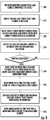
- FIG. 7A is a flow diagram illustrating an exemplary method according to the disclosure.
- a voltage is applied between first and second surfaces associated with an oxy-fuel cutting system.
- the first and second surfaces are a torch surface and a work piece, respectively.
- the first and second surfaces may be exposed to the flame of an oxy-fuel torch during operation.
- a current generated in response to the applied voltage is sensed.
- a first parameter associated with a cutting process is determined based on the applied voltage and the sensed current.
- a determination is made about whether the first parameter is within a predetermined range.
- a second parameter associated with the cutting process is adjusted.
- FIG. 7B is a flow diagram illustrating an exemplary method according to the disclosure.
- a current is driven between first and second surfaces associated with an oxy-fuel cutting system.
- the first and second surfaces are a torch surface and a work piece, respectively.
- the first and second surfaces are exposed to the flame of an oxy-fuel torch during operation.
- a voltage generated in response to the driven current is sensed.
- a first parameter associated with a cutting process is determined based on the driven current and the sensed voltage.
- a determination is made about whether the first parameter is within a predetermined range.
- a second parameter associated with the cutting process is adjusted.
- the torch system 50 may include a gas cutting torch 52 (hereinafter “the torch 52") that is operatively mounted to a computer numerical control (CNC) machine 54 or other automated machine tool that is capable of moving the torch 52 along a predefined path, such as may be specified in a software file.
- the torch 52 is shown generically connected to the CNC machine 14, but it will be appreciated that in practical application the torch 52 will be mounted to the CNC machine 54 in a manner that facilitates 2-dimensional or 3-dimensional movement of the torch 52 as further described below.
- the torch 52 may be any type of gas cutting torch, including, but not limited to, an oxy-fuel torch, a propane torch, a propylene torch, a butane torch, or a mixed-fuel torch.
- the cutting system 50 may also include a controller 16, which in one embodiment comprises a microprocessor.
- the controller 16 may include a circuit 58 including an electrical power source 20 connected electrically in series with a resistor 22 or other current or voltage measurement device.
- the power source 20 may be a voltage source or a current source.
- the power source 20 is a voltage source, in which case a current may be induced and measured in the circuit 58 as further described below.
- the power source 20 may alternatively be a current source, in which case a voltage may be induced and measured between the torch 52 and a work piece 66 (described below).
- one side of the circuit 58 may be electrically connected to the torch 52, such as by a first conductor 24, and the other side of the circuit 58 may be electrically connected to a work piece 66 that is to be cut by the torch 52, such as by a second conductor 68.
- the circuit 58 may further include a switch 30 for connecting the torch 52 to ground when the cutting system 50 it is not in operation, thereby preventing the buildup of static electricity in the circuit 58.
- the circuit 58 may include additional switches (as shown in FIGS. 10 - 12 ) for placing the torch in and out of electrical communication with circuits for ignition as further described below.
- the controller 16 may further include a processor 72 that is capable of executing a number of predefined instructions.
- the processor 72 may be operatively connected to the power source 20 for regulating an amount of voltage output therefrom as further described below, and may also be electrically coupled the circuit 58, such as at points A and B, for measuring an amount of current flowing in the circuit 58.
- the processor 30 may further be operatively connected to the CNC machine 54 and to the torch 52 for controlling/modifying the operation thereof as described in greater detail below.
- the processor 72 may further be operatively connected to the switch 30 for controlling the operation thereof, such as for selectively moving switch between a closed position, wherein the torch 52 is connected to the circuit 58 (e.g.
- a non-volatile memory may be associated with the processor 72 for storing software instructions executed by the processor 72 and/or for storing data collected from the circuit 58.
- FIG. 8 a flow diagram illustrating an exemplary method of operating the cutting system 50 in accordance with the present disclosure is shown.
- the method exploits the electrically conductive nature of the torch's flame to determine the state of the work piece 66 being cut before and during cutting.
- the high-temperature gases present in the torch's flame are sufficiently dissociated so that if a voltage is applied between the torch 52 and the work piece 66 a current will flow through the flame. This principle will be described in greater detail below in the context of the exemplary method.
- the work piece 66 may be manually or automatically positioned below the unlit torch 52 and connected to the circuit 58, such as by the conductor 68.
- the conductor 68 may be connected to the work piece through the table, such as by an alligator clip or some similar means of electrically conductive attachment.
- the nozzle 74 of the torch may initially be disposed well above the surface of the work piece 66, such as at a standoff distance "SD" of 152.4 - 304.8 mm (6-12 inches) for example. If the switch 70 is in the open position, the processor 72 may direct the switch to move to the closed position, thereby placing the torch in electrical communication with the circuit 58.
- the processor 72 may command the power source 60 to output a relatively low voltage, a non-limiting example of which is 12V.
- the processor 72 may then command the CNC machine 54 to slowly lower the unlit torch 52 until the processor 72 detects current flowing in the circuit 58 between connection points "A" and "B", indicating that the nozzle 74 of the torch 52 has been brought into contact with the work piece 66 to complete the circuit 58.
- the processor 72 may then record the height of the torch 52 in this position as a "zero height" (i.e. the height of the upper surface of the work piece 66). This height may be stored in volatile or non-volatile memory associated with the processor.
- the processor may command the CNC machine 54 to elevate the torch 52 away from the work piece 66.
- the processor 72 may simultaneously direct the power source 60 to charge an energy storage device (described below) that is electrically connected within the circuit 58.
- the energy storage device may be a capacitor bank 78, in which case one or more capacitors in electrical communication with the torch 52 and some other surface (e.g. the work piece 66) may be charged in advance to a predetermined voltage and discharged when the CNC machine 54 moves the torch 52 into contact with said surface.
- the processor may command the CNC machine 54 to elevate the torch 52 away from the work piece 66.
- the processor 72 may simultaneously direct the power source 60 to charge an energy storage device (described below) that is electrically connected within the circuit 58.
- the energy storage device may be a capacitor bank 78, in which case one or more capacitors in electrical communication with the torch 52 and some other surface (e.g. the work piece 66) may be charged in advance to a predetermined voltage and discharged when the CNC machine 54 moves the torch 52
- the energy storage device may be an inductor 80 that is in electrical communication with the torch 52, in which case a switch 82 may be closed to induce a current in an inductor 80, wherein the energy stored in the inductor 80 is discharged once the torch 52 is moved into the proximity of the work piece 66 or other surface and the switch 82 is opened.
- the processor 72 has commanded activation of a flow of gas from the torch 52 (e.g. by actuation of appropriate solenoid valves), and has properly positioned the torch 52 in advance, then the above-described discharge of electrical energy may create an ignition site in the gap between the torch 52 and the work piece 66 or other surface, thereby igniting the stream of gas flowing therethrough.
- This process may be enhanced by imposing some combination of oscillating voltages or high voltages to increase the gap distances over which ignition can occur, as shown in FIG. 12 .
- the processor 72 may detect successful ignition of the gas by directing the voltage source to output a relatively low voltage, a non-limiting example of which is 24V, after discharge of the capacitors. If the fuel gas was successfully ignited by the discharge, a small current will flow through the flame 76 and will be detected by the processor 72 between points "A" and "B" in the circuit 58. If, by contrast, ignition was not successful, there will be no flame 76 and therefore no detectable current in the circuit 58. In the case of ignition failure, the processor 72 may repeat the entire ignition process (i.e. step 220 of the method) until successful ignition is detected.
- a relatively low voltage a non-limiting example of which is 24V
- the processor 72 may direct the CNC machine 54 to raise the torch 52 until the nozzle 74 reaches a predefined standoff distance "SD" relative to the known zero height (i.e. the surface of the work piece 66).
- the processor 72 may then direct the power source 60 to output a low voltage, a non-limiting example of which is 12V.
- a low voltage a non-limiting example of which is 12V.
- the current in the circuit 58 will be determined by the resistance of the path between the torch 52 and the work piece 66 or some other surface. Such resistance is highly sensitive to variations in the quality of the flame 76.
- the gas mixture in the torch 52 e.g.
- the ratio of fuel gas to oxygen may be adjusted until a desired current value in circuit 58, as determined by the processor 72, is achieved at the predefined standoff distance "SD", where this desired current value is indicative of a desired quality of flame 76.
- the desired current value may be indicative of a flame 38 that is suited for preheating the work piece 66 prior to cutting.
- the processor 72 may command the CNC machine 54 to move the torch 52 to a designated location along the surface of the work piece 66 where cutting is to begin.
- the processor 72 may then adjust the voltage in the circuit 58 to maintain a constant current, such as may be achieved by directing the CNC machine 54 to adjust the standoff distance "Y.” That is, when the standoff distance "Y" is increased, the voltage in the circuit 58 increases and the current in the circuit 58 decreases. Conversely, when the standoff distance "Y" is decreased, the voltage in the circuit 58 decreases and the current in the circuit 58 increases.
- the processor 72 may in this way utilize the measured current in the circuit 58 to maintain a consistent standoff distance "Y" relative to the work piece regardless of variations in the surface of the work piece 66. This principle is described in U.S. Patent Numbers 4,328,049 and 3,823,928 .
- the processor 72 may command the power source 60 to increase its output voltage to a predefined maximum value at which the current in the circuit 58 is guaranteed to be limited by electron evaporation from the work piece 66.
- This predefined maximum value may be determined from the geometry and flow rate of the torch 52, for example. Such parameters may be known in advance, and an operator may consult a schedule of voltages or currents that are known to be important. Other examples not covered by the present invention of the present method may include looking for current-voltage sensitivities (i.e. the relationship between a change in current relative to a change in voltage).
- the current in the circuit 58 will increase coherently with the temperature of the work piece 66. It will be appreciated by those of skill in the art that when a material, particularly metal, is sufficiently heated, the increased kinetic energy exhibited by the electrons of the material may allow the electrons to momentarily escape from the material's boundaries. If an anode that is charged with a sufficiently large voltage is placed in the vicinity of the material, the electrons that escape from the material will be pulled away by the charged anode at exactly the same rate at which they evaporate from the material. This rate of evaporation is known to be a function of the temperature of the material.
- the current in the circuit 58 may be used to reliably determine the temperature of the work piece 66.
- a predefined level such as a level indicative of a kindling temperature in the work piece 66
- preheating of the work piece 66 is complete and cutting can begin.
- cutting the preheated work piece 66 may be achieved by activating the flow of cutting oxygen.
- the CNC machine 54 may move the torch 52 along the work piece 66 in accordance with a predefined cutting path at an appropriate speed for maintaining the quality of the cut.
- the desired standoff distance "SD" may be maintained by continuously performing the torch height adjustment as described in step 250 above.
- oxidation on the surface of a work piece may form a barrier that resists current flow for contact sensing (as described in step 120 above) and/or that resists electrical arcing for torch gas ignition (as described in step 130 above).
- U.S. Patent No. 7,087,856 describes a method for detecting contact through oxidation layers on a work piece in a manner that is safe to humans (i.e. that does not involve the application of high voltage or high frequency energy for an appreciable amount of time). It is contemplated that such a method may be similarly implemented in the context of the present disclosure for contact sensing and/or for torch gas ignition.
- the effect of oxidation or surface irregularities may be compensated for by taking initial calibration measurements when the work piece is in a known condition.
- a non-limiting example of this would be positioning the ignited torch 52 above a plate known to be at or near ambient temperature, and applying sufficient voltage so as to drive a current limited by thermionic emission from the plate.
- This calibration current sensed at this condition is an indication of the plate condition.
- the kindling temperature can then be recognized by when the measured current increases by some pre-determined amount relative to the calibration current.
- the cutting system 50 and accompanying method of the present disclosure provide a number of important advantages relative to existing automated cutting torch systems. Particularly, the system and method facilitate features such as automatic standoff control, automatic ignition, ignition detection, flame quality detection, and kindling temperature detection without requiring many of the moving parts, on-board electronics, and sensors associated with existing torch systems.
- the cutting system 50 of the present disclosure is therefore far more economical, reliable, and robust than existing systems.
- Some embodiments of the disclosed device may be implemented, for example, using a storage medium, a computer-readable medium or an article of manufacture which may store an instruction or a set of instructions that, if executed by a machine, may cause the machine to perform a method and/or operations in accordance with embodiments of the disclosure.
- a machine may include, for example, any suitable processing platform, computing platform, computing device, processing device, computing system, processing system, computer, processor, or the like, and may be implemented using any suitable combination of hardware and/or software.
- the computer-readable medium or article may include, for example, any suitable type of memory unit, memory device, memory article, memory medium, storage device, storage article, storage medium and/or storage unit, for example, memory (including non-transitory memory), removable or non-removable media, erasable or non-erasable media, writeable or re-writeable media, digital or analog media, hard disk, floppy disk, Compact Disk Read Only Memory (CD-ROM), Compact Disk Recordable (CD-R), Compact Disk Rewriteable (CD-RW), optical disk, magnetic media, magneto-optical media, removable memory cards or disks, various types of Digital Versatile Disk (DVD), a tape, a cassette, or the like.
- memory including non-transitory memory
- removable or non-removable media erasable or non-erasable media, writeable or re-writeable media, digital or analog media
- hard disk floppy disk
- CD-ROM Compact Disk Read Only Memory
- CD-R Compact Disk Recordable
- the instructions may include any suitable type of code, such as source code, compiled code, interpreted code, executable code, static code, dynamic code, encrypted code, and the like, implemented using any suitable high-level, low-level, object-oriented, visual, compiled and/or interpreted programming language.
Landscapes
- Engineering & Computer Science (AREA)
- Mechanical Engineering (AREA)
- Automation & Control Theory (AREA)
- Physics & Mathematics (AREA)
- General Physics & Mathematics (AREA)
- Electromagnetism (AREA)
- Radar, Positioning & Navigation (AREA)
- Power Engineering (AREA)
- Human Computer Interaction (AREA)
- Manufacturing & Machinery (AREA)
- General Engineering & Computer Science (AREA)
- Perforating, Stamping-Out Or Severing By Means Other Than Cutting (AREA)
- Arc Welding In General (AREA)
- Laser Beam Processing (AREA)
Claims (9)
- Un système de traitement thermique d'oxygaz, comprenant :un chalumeau (1) ayant une première surface ;une pièce à travailler (14) ayant une deuxième surfaceun entraîneur de courant (32) couplé entre les première et deuxième surfaces pour entraîner un courant entre les première et deuxième surfaces, les première etdeuxième surfaces étant exposées à une flamme (16) du chalumeau (1) ;un détecteur de tension (34) couplé entre les première et deuxième surfaces pour détecter une réponse de tension à un courant entraîné fourni par l'entraîneur de courant (32) ; caractérisé parun microprocesseur en communication avec l'entraîneur de courant (32) et le détecteur de tension (34) et configuré pour recevoir des informations du courant entraîné et de la réponse de tension détectée, le microprocesseur étant en outre configuré pour calculer une pente dans le régime linéaire de la relation courant-tension (I-V) caractéristique du courant entraîné et de la réponse de tension détectée associée à un procédé thermique du système de traitement thermique d'oxygaz, et pour déterminer si la pente se trouve dans les limites d'un intervalle prédéterminé, et lorsqu'il est déterminé que la pente se trouve en dehors de l'intervalle prédéterminé, pour donner l'instruction d'ajuster un mélange gazeux associé au procédé thermique.
- Le système de procédé thermique d'oxygaz de la revendication 1, dans lequel la pente est représentative d'un mélange gazeux fourni à la flamme (16).
- Le système de traitement thermique d'oxygaz de la revendication 1, dans lequel la pente est représentative de si la flamme (16) est allumée ou non.
- Le système de traitement thermique d'oxygaz de la revendication 1, dans lequel le processeur est configuré pour calculer la pente tandis qu'un traitement thermique d'une pièce à travailler (14) est en cours de réalisation.
- Le système de traitement thermique d'oxygaz de la revendication 4, dans lequel la pente est représentative d'une perte de découpe imminente.
- Le système de traitement thermique d'oxygaz de la revendication 4, dans lequel la pente est représentative d'une température de la pièce à travailler (14).
- Une méthode pour commander un procédé de traitement thermique d'oxygaz, comprenant :l'application d'un courant entre des première et deuxième surfaces tandis que les première et deuxième surfaces sont exposées à une flamme (16) d'un chalumeau (1), où la première surface est une surface du chalumeau (1) et la deuxième surface est une surface d'une pièce à travailler (14) ;la détection d'une tension entre la première surface et la deuxième surface générée en réponse au courant appliqué ;la réception d'informations du courant appliqué et de la tension détectée ;le calcul d'une pente dans le régime linéaire de la relation courant-tension (I-V) caractéristique du courant appliqué et de la tension détectée associée à un procédé thermique du système de traitement thermique d'oxygaz ; la méthode étant caractérisée parla détermination de savoir si la pente se trouve dans les limites d'un intervalle prédéterminé, et lorsqu'il est déterminé que la pente se trouve en dehors de l'intervalle prédéterminé, le fait de donner l'instruction d'ajuster un mélange gazeux associé au procédé thermique.
- La méthode de la revendication 7, dans laquelle le courant appliqué comprend un signal oscillant ayant une amplitude fixe.
- La méthode de la revendication 7, comprenant en outre la mesure d'un courant de seuil de saturation et d'une tension de seuil de saturation.
Applications Claiming Priority (2)
| Application Number | Priority Date | Filing Date | Title |
|---|---|---|---|
| US201361786956P | 2013-03-15 | 2013-03-15 | |
| PCT/US2014/025938 WO2014151534A1 (fr) | 2013-03-15 | 2014-03-13 | Détection d'état de pièce à usiner en utilisant les caractéristiques électriques de la flamme d'un équipement de traitement thermique par oxycombustion |
Publications (3)
| Publication Number | Publication Date |
|---|---|
| EP2969345A1 EP2969345A1 (fr) | 2016-01-20 |
| EP2969345A4 EP2969345A4 (fr) | 2016-10-19 |
| EP2969345B1 true EP2969345B1 (fr) | 2021-10-20 |
Family
ID=51580981
Family Applications (1)
| Application Number | Title | Priority Date | Filing Date |
|---|---|---|---|
| EP14767439.4A Active EP2969345B1 (fr) | 2013-03-15 | 2014-03-13 | Détection des paramètres de procédé à l'aide des caractéristiques électriques de la flamme dans le traitement thermique oxy-combustible |
Country Status (4)
| Country | Link |
|---|---|
| US (3) | US10067496B2 (fr) |
| EP (1) | EP2969345B1 (fr) |
| ES (1) | ES2900724T3 (fr) |
| WO (1) | WO2014151534A1 (fr) |
Families Citing this family (6)
| Publication number | Priority date | Publication date | Assignee | Title |
|---|---|---|---|---|
| DE102017003388A1 (de) | 2017-04-06 | 2018-10-11 | Linde Aktiengesellschaft | Verfahren zum Flammrichten und Brenneranordnung hierfür |
| JP7034474B2 (ja) * | 2018-02-06 | 2022-03-14 | 吉川工業株式会社 | 異形鋼片の切断システム |
| US11213912B2 (en) * | 2018-06-25 | 2022-01-04 | Bwxt Nuclear Operations Group, Inc. | Methods and systems for monitoring a temperature of a component during a welding operation |
| US11511381B2 (en) * | 2018-08-29 | 2022-11-29 | Illinois Tool Works Inc. | Movement control of material removal systems |
| EP4122631B1 (fr) * | 2021-07-06 | 2025-08-20 | IHT Automation GmbH & Co. KG | Procédé de surveillance d'un processus d'oxycoupage |
| US11684989B2 (en) | 2021-07-06 | 2023-06-27 | Iht Automation Gmbh & Co. Kg | Method for monitoring a flame cutting process |
Citations (1)
| Publication number | Priority date | Publication date | Assignee | Title |
|---|---|---|---|---|
| DE102009033556A1 (de) * | 2009-07-16 | 2011-01-20 | Gottfried Wilhelm Leibniz Universität Hannover | Verfahren und Vorrichtung mit einer autogenen Brennereinrichtung |
Family Cites Families (14)
| Publication number | Priority date | Publication date | Assignee | Title |
|---|---|---|---|---|
| US2949391A (en) * | 1958-04-30 | 1960-08-16 | Air Reduction | Method and apparatus for automatic torch positioning |
| US3823928A (en) * | 1972-12-01 | 1974-07-16 | Caterpillar Tractor Co | Torch height control for flame cutting machines |
| US4170727A (en) * | 1978-05-19 | 1979-10-09 | Thermal Dynamics Corporation | Thermal torch height acquisition circuit |
| US4328049A (en) | 1979-03-20 | 1982-05-04 | Caterpillar Tractor Co. | Torch height sensing apparatus |
| WO1980002002A1 (fr) * | 1979-03-20 | 1980-10-02 | Caterpillar Tractor Co | Appareil de controle de la hauteur d'un chalumeau de decoupage |
| US4439249A (en) | 1983-06-22 | 1984-03-27 | Victor Equipment Company | Automated cutting of plate steel |
| DD249598A3 (de) | 1985-03-18 | 1987-09-16 | Zi F Schweisstechnik Der Ddr L | Verfahren und vorrichtung der prozesskontrolle beim thermischen trennen |
| US4854551A (en) * | 1987-09-10 | 1989-08-08 | Cleveland Machine Controls, Inc. | Device for controlling operating gap of cutting head and method of using same |
| US5470047A (en) | 1993-06-23 | 1995-11-28 | Daewood Heavy Industries Co., Ltd. | Electrical flame sensor for use in a gas cutting apparatus |
| JP3269365B2 (ja) | 1995-11-29 | 2002-03-25 | 松下電器産業株式会社 | アークセンサ装置 |
| DE19739351C1 (de) * | 1997-09-08 | 1999-01-21 | Messer Griesheim Schweistechni | Koordinaten-Brennschneidmaschine mit einer Einrichtung zum automatischen Einstellen der Anfangshöhe eines Brenners |
| FR2787050B1 (fr) | 1998-12-10 | 2001-02-09 | Safmatic | Installation de coupage de metaux munie d'une torche de coupage et d'une sonde capacitive de palpage |
| WO2011082492A1 (fr) * | 2010-01-11 | 2011-07-14 | Oxy-Arc International, Inc. | Procédé et système pour commander un chalumeau |
| KR101186668B1 (ko) | 2010-08-18 | 2012-09-27 | 고종철 | 용접작업의 원격 모니터링시스템 |
-
2014
- 2014-03-13 EP EP14767439.4A patent/EP2969345B1/fr active Active
- 2014-03-13 ES ES14767439T patent/ES2900724T3/es active Active
- 2014-03-13 WO PCT/US2014/025938 patent/WO2014151534A1/fr not_active Ceased
- 2014-03-13 US US14/777,313 patent/US10067496B2/en active Active
-
2018
- 2018-07-18 US US16/038,359 patent/US10514675B2/en active Active
-
2019
- 2019-11-11 US US16/679,460 patent/US11507045B2/en active Active
Patent Citations (1)
| Publication number | Priority date | Publication date | Assignee | Title |
|---|---|---|---|---|
| DE102009033556A1 (de) * | 2009-07-16 | 2011-01-20 | Gottfried Wilhelm Leibniz Universität Hannover | Verfahren und Vorrichtung mit einer autogenen Brennereinrichtung |
Also Published As
| Publication number | Publication date |
|---|---|
| US20180321657A1 (en) | 2018-11-08 |
| ES2900724T3 (es) | 2022-03-18 |
| US10067496B2 (en) | 2018-09-04 |
| EP2969345A4 (fr) | 2016-10-19 |
| US20200096964A1 (en) | 2020-03-26 |
| WO2014151534A1 (fr) | 2014-09-25 |
| EP2969345A1 (fr) | 2016-01-20 |
| US20160018812A1 (en) | 2016-01-21 |
| US10514675B2 (en) | 2019-12-24 |
| US11507045B2 (en) | 2022-11-22 |
Similar Documents
| Publication | Publication Date | Title |
|---|---|---|
| US11507045B2 (en) | Work piece condition detection using flame electrical characteristics in oxy-fuel thermal processing equipment | |
| CN103282153B (zh) | 用于学习/检查焊接机器人的运动过程的方法、焊接机器人及用于焊接机器人的控制装置 | |
| US5349156A (en) | Sensing of gas metal arc welding process characteristics for welding process control | |
| US20130277344A1 (en) | Robotic pre-heat and inter-pass welding | |
| US3262006A (en) | Welding control system | |
| JPH11156553A (ja) | プラズマアークトーチの電極又はノズルの少なくとも一方の磨耗検出方法及び装置 | |
| KR920020997A (ko) | 플라즈마 노즐을 보호하기 위한 시스템, 방법 및 회로 | |
| Zhang et al. | Efflux plasma charge-based sensing and control of joint penetration during keyhole plasma arc welding | |
| JP6834023B2 (ja) | 溶接ワイヤ電極を用いて金属ワークのワーク表面にマーキングするための方法および装置 | |
| WO1995026251A1 (fr) | Controle de l'etat d'un chalumeau a l'arc de plasma | |
| CA2475652A1 (fr) | Methode et appareil d'autodetection de produits non durables | |
| Pond et al. | Electrical characteristics of the oxyfuel flame while cutting steel | |
| Ancona et al. | A sensing torch for on-line monitoring of the gas tungsten arc welding process of steel pipes | |
| US11684989B2 (en) | Method for monitoring a flame cutting process | |
| CN107249804B (zh) | 穿透焊接方法 | |
| JP5818005B2 (ja) | 抵抗溶接装置の検査方法及び偏磁電流計測器 | |
| US12220773B2 (en) | Welding system | |
| CN105728900A (zh) | 窄间隙焊接温度场的测量方法及系统 | |
| JP2627017B2 (ja) | ガス切断機の失火検知装置 | |
| JPH07244018A (ja) | ガス切断装置用火炎センサ | |
| ES2428414T3 (es) | Procedimiento para la determinación de la distancia entre un dispositivo quemador autógeno y una pieza de trabajo mediante detección de un parámetro sin un suministro de energía eléctrica propio | |
| KR101696278B1 (ko) | 성능 검사를 위한 시편 가열 장치 및 그 제어 방법 | |
| JP3067781B2 (ja) | 加熱調理制御方法 | |
| KR102631684B1 (ko) | 레이저 절단기용 강판 특성 감지 장치 | |
| US11890693B2 (en) | Systems and methods for determining characteristics of a workpiece in a plasma arc processing system |
Legal Events
| Date | Code | Title | Description |
|---|---|---|---|
| PUAI | Public reference made under article 153(3) epc to a published international application that has entered the european phase |
Free format text: ORIGINAL CODE: 0009012 |
|
| 17P | Request for examination filed |
Effective date: 20150918 |
|
| AK | Designated contracting states |
Kind code of ref document: A1 Designated state(s): AL AT BE BG CH CY CZ DE DK EE ES FI FR GB GR HR HU IE IS IT LI LT LU LV MC MK MT NL NO PL PT RO RS SE SI SK SM TR |
|
| AX | Request for extension of the european patent |
Extension state: BA ME |
|
| DAX | Request for extension of the european patent (deleted) | ||
| A4 | Supplementary search report drawn up and despatched |
Effective date: 20160920 |
|
| RIC1 | Information provided on ipc code assigned before grant |
Ipc: B23K 5/00 20060101ALI20160914BHEP Ipc: G05B 19/402 20060101ALI20160914BHEP Ipc: G05B 15/02 20060101ALI20160914BHEP Ipc: B23K 5/22 20060101ALI20160914BHEP Ipc: B23K 7/00 20060101AFI20160914BHEP Ipc: G05F 1/625 20060101ALI20160914BHEP Ipc: B23K 7/10 20060101ALI20160914BHEP |
|
| STAA | Information on the status of an ep patent application or granted ep patent |
Free format text: STATUS: EXAMINATION IS IN PROGRESS |
|
| 17Q | First examination report despatched |
Effective date: 20181126 |
|
| GRAP | Despatch of communication of intention to grant a patent |
Free format text: ORIGINAL CODE: EPIDOSNIGR1 |
|
| STAA | Information on the status of an ep patent application or granted ep patent |
Free format text: STATUS: GRANT OF PATENT IS INTENDED |
|
| INTG | Intention to grant announced |
Effective date: 20210512 |
|
| GRAS | Grant fee paid |
Free format text: ORIGINAL CODE: EPIDOSNIGR3 |
|
| GRAA | (expected) grant |
Free format text: ORIGINAL CODE: 0009210 |
|
| STAA | Information on the status of an ep patent application or granted ep patent |
Free format text: STATUS: THE PATENT HAS BEEN GRANTED |
|
| AK | Designated contracting states |
Kind code of ref document: B1 Designated state(s): AL AT BE BG CH CY CZ DE DK EE ES FI FR GB GR HR HU IE IS IT LI LT LU LV MC MK MT NL NO PL PT RO RS SE SI SK SM TR |
|
| REG | Reference to a national code |
Ref country code: GB Ref legal event code: FG4D |
|
| REG | Reference to a national code |
Ref country code: CH Ref legal event code: EP |
|
| REG | Reference to a national code |
Ref country code: IE Ref legal event code: FG4D |
|
| REG | Reference to a national code |
Ref country code: DE Ref legal event code: R096 Ref document number: 602014080771 Country of ref document: DE |
|
| REG | Reference to a national code |
Ref country code: AT Ref legal event code: REF Ref document number: 1439517 Country of ref document: AT Kind code of ref document: T Effective date: 20211115 |
|
| REG | Reference to a national code |
Ref country code: LT Ref legal event code: MG9D |
|
| REG | Reference to a national code |
Ref country code: NL Ref legal event code: MP Effective date: 20211020 |
|
| REG | Reference to a national code |
Ref country code: AT Ref legal event code: MK05 Ref document number: 1439517 Country of ref document: AT Kind code of ref document: T Effective date: 20211020 |
|
| REG | Reference to a national code |
Ref country code: ES Ref legal event code: FG2A Ref document number: 2900724 Country of ref document: ES Kind code of ref document: T3 Effective date: 20220318 |
|
| PG25 | Lapsed in a contracting state [announced via postgrant information from national office to epo] |
Ref country code: RS Free format text: LAPSE BECAUSE OF FAILURE TO SUBMIT A TRANSLATION OF THE DESCRIPTION OR TO PAY THE FEE WITHIN THE PRESCRIBED TIME-LIMIT Effective date: 20211020 Ref country code: LT Free format text: LAPSE BECAUSE OF FAILURE TO SUBMIT A TRANSLATION OF THE DESCRIPTION OR TO PAY THE FEE WITHIN THE PRESCRIBED TIME-LIMIT Effective date: 20211020 Ref country code: FI Free format text: LAPSE BECAUSE OF FAILURE TO SUBMIT A TRANSLATION OF THE DESCRIPTION OR TO PAY THE FEE WITHIN THE PRESCRIBED TIME-LIMIT Effective date: 20211020 Ref country code: BG Free format text: LAPSE BECAUSE OF FAILURE TO SUBMIT A TRANSLATION OF THE DESCRIPTION OR TO PAY THE FEE WITHIN THE PRESCRIBED TIME-LIMIT Effective date: 20220120 Ref country code: AT Free format text: LAPSE BECAUSE OF FAILURE TO SUBMIT A TRANSLATION OF THE DESCRIPTION OR TO PAY THE FEE WITHIN THE PRESCRIBED TIME-LIMIT Effective date: 20211020 |
|
| PG25 | Lapsed in a contracting state [announced via postgrant information from national office to epo] |
Ref country code: IS Free format text: LAPSE BECAUSE OF FAILURE TO SUBMIT A TRANSLATION OF THE DESCRIPTION OR TO PAY THE FEE WITHIN THE PRESCRIBED TIME-LIMIT Effective date: 20220220 Ref country code: SE Free format text: LAPSE BECAUSE OF FAILURE TO SUBMIT A TRANSLATION OF THE DESCRIPTION OR TO PAY THE FEE WITHIN THE PRESCRIBED TIME-LIMIT Effective date: 20211020 Ref country code: PT Free format text: LAPSE BECAUSE OF FAILURE TO SUBMIT A TRANSLATION OF THE DESCRIPTION OR TO PAY THE FEE WITHIN THE PRESCRIBED TIME-LIMIT Effective date: 20220221 Ref country code: PL Free format text: LAPSE BECAUSE OF FAILURE TO SUBMIT A TRANSLATION OF THE DESCRIPTION OR TO PAY THE FEE WITHIN THE PRESCRIBED TIME-LIMIT Effective date: 20211020 Ref country code: NO Free format text: LAPSE BECAUSE OF FAILURE TO SUBMIT A TRANSLATION OF THE DESCRIPTION OR TO PAY THE FEE WITHIN THE PRESCRIBED TIME-LIMIT Effective date: 20220120 Ref country code: NL Free format text: LAPSE BECAUSE OF FAILURE TO SUBMIT A TRANSLATION OF THE DESCRIPTION OR TO PAY THE FEE WITHIN THE PRESCRIBED TIME-LIMIT Effective date: 20211020 Ref country code: LV Free format text: LAPSE BECAUSE OF FAILURE TO SUBMIT A TRANSLATION OF THE DESCRIPTION OR TO PAY THE FEE WITHIN THE PRESCRIBED TIME-LIMIT Effective date: 20211020 Ref country code: HR Free format text: LAPSE BECAUSE OF FAILURE TO SUBMIT A TRANSLATION OF THE DESCRIPTION OR TO PAY THE FEE WITHIN THE PRESCRIBED TIME-LIMIT Effective date: 20211020 Ref country code: GR Free format text: LAPSE BECAUSE OF FAILURE TO SUBMIT A TRANSLATION OF THE DESCRIPTION OR TO PAY THE FEE WITHIN THE PRESCRIBED TIME-LIMIT Effective date: 20220121 |
|
| REG | Reference to a national code |
Ref country code: DE Ref legal event code: R097 Ref document number: 602014080771 Country of ref document: DE |
|
| PG25 | Lapsed in a contracting state [announced via postgrant information from national office to epo] |
Ref country code: SM Free format text: LAPSE BECAUSE OF FAILURE TO SUBMIT A TRANSLATION OF THE DESCRIPTION OR TO PAY THE FEE WITHIN THE PRESCRIBED TIME-LIMIT Effective date: 20211020 Ref country code: SK Free format text: LAPSE BECAUSE OF FAILURE TO SUBMIT A TRANSLATION OF THE DESCRIPTION OR TO PAY THE FEE WITHIN THE PRESCRIBED TIME-LIMIT Effective date: 20211020 Ref country code: RO Free format text: LAPSE BECAUSE OF FAILURE TO SUBMIT A TRANSLATION OF THE DESCRIPTION OR TO PAY THE FEE WITHIN THE PRESCRIBED TIME-LIMIT Effective date: 20211020 Ref country code: EE Free format text: LAPSE BECAUSE OF FAILURE TO SUBMIT A TRANSLATION OF THE DESCRIPTION OR TO PAY THE FEE WITHIN THE PRESCRIBED TIME-LIMIT Effective date: 20211020 Ref country code: DK Free format text: LAPSE BECAUSE OF FAILURE TO SUBMIT A TRANSLATION OF THE DESCRIPTION OR TO PAY THE FEE WITHIN THE PRESCRIBED TIME-LIMIT Effective date: 20211020 |
|
| PLBE | No opposition filed within time limit |
Free format text: ORIGINAL CODE: 0009261 |
|
| STAA | Information on the status of an ep patent application or granted ep patent |
Free format text: STATUS: NO OPPOSITION FILED WITHIN TIME LIMIT |
|
| 26N | No opposition filed |
Effective date: 20220721 |
|
| PG25 | Lapsed in a contracting state [announced via postgrant information from national office to epo] |
Ref country code: MC Free format text: LAPSE BECAUSE OF FAILURE TO SUBMIT A TRANSLATION OF THE DESCRIPTION OR TO PAY THE FEE WITHIN THE PRESCRIBED TIME-LIMIT Effective date: 20211020 Ref country code: AL Free format text: LAPSE BECAUSE OF FAILURE TO SUBMIT A TRANSLATION OF THE DESCRIPTION OR TO PAY THE FEE WITHIN THE PRESCRIBED TIME-LIMIT Effective date: 20211020 |
|
| REG | Reference to a national code |
Ref country code: CH Ref legal event code: PL |
|
| PG25 | Lapsed in a contracting state [announced via postgrant information from national office to epo] |
Ref country code: SI Free format text: LAPSE BECAUSE OF FAILURE TO SUBMIT A TRANSLATION OF THE DESCRIPTION OR TO PAY THE FEE WITHIN THE PRESCRIBED TIME-LIMIT Effective date: 20211020 |
|
| REG | Reference to a national code |
Ref country code: BE Ref legal event code: MM Effective date: 20220331 |
|
| PG25 | Lapsed in a contracting state [announced via postgrant information from national office to epo] |
Ref country code: LU Free format text: LAPSE BECAUSE OF NON-PAYMENT OF DUE FEES Effective date: 20220313 Ref country code: LI Free format text: LAPSE BECAUSE OF NON-PAYMENT OF DUE FEES Effective date: 20220331 Ref country code: IE Free format text: LAPSE BECAUSE OF NON-PAYMENT OF DUE FEES Effective date: 20220313 Ref country code: CH Free format text: LAPSE BECAUSE OF NON-PAYMENT OF DUE FEES Effective date: 20220331 |
|
| PG25 | Lapsed in a contracting state [announced via postgrant information from national office to epo] |
Ref country code: BE Free format text: LAPSE BECAUSE OF NON-PAYMENT OF DUE FEES Effective date: 20220331 |
|
| P01 | Opt-out of the competence of the unified patent court (upc) registered |
Effective date: 20230522 |
|
| PG25 | Lapsed in a contracting state [announced via postgrant information from national office to epo] |
Ref country code: HU Free format text: LAPSE BECAUSE OF FAILURE TO SUBMIT A TRANSLATION OF THE DESCRIPTION OR TO PAY THE FEE WITHIN THE PRESCRIBED TIME-LIMIT; INVALID AB INITIO Effective date: 20140313 |
|
| PG25 | Lapsed in a contracting state [announced via postgrant information from national office to epo] |
Ref country code: MK Free format text: LAPSE BECAUSE OF FAILURE TO SUBMIT A TRANSLATION OF THE DESCRIPTION OR TO PAY THE FEE WITHIN THE PRESCRIBED TIME-LIMIT Effective date: 20211020 Ref country code: CY Free format text: LAPSE BECAUSE OF FAILURE TO SUBMIT A TRANSLATION OF THE DESCRIPTION OR TO PAY THE FEE WITHIN THE PRESCRIBED TIME-LIMIT Effective date: 20211020 |
|
| PG25 | Lapsed in a contracting state [announced via postgrant information from national office to epo] |
Ref country code: MT Free format text: LAPSE BECAUSE OF FAILURE TO SUBMIT A TRANSLATION OF THE DESCRIPTION OR TO PAY THE FEE WITHIN THE PRESCRIBED TIME-LIMIT Effective date: 20211020 |
|
| PGFP | Annual fee paid to national office [announced via postgrant information from national office to epo] |
Ref country code: ES Payment date: 20250401 Year of fee payment: 12 |
|
| PG25 | Lapsed in a contracting state [announced via postgrant information from national office to epo] |
Ref country code: TR Free format text: LAPSE BECAUSE OF FAILURE TO SUBMIT A TRANSLATION OF THE DESCRIPTION OR TO PAY THE FEE WITHIN THE PRESCRIBED TIME-LIMIT Effective date: 20211020 |
|
| PGFP | Annual fee paid to national office [announced via postgrant information from national office to epo] |
Ref country code: GB Payment date: 20260327 Year of fee payment: 13 |
|
| PGFP | Annual fee paid to national office [announced via postgrant information from national office to epo] |
Ref country code: DE Payment date: 20260327 Year of fee payment: 13 |
|
| PGFP | Annual fee paid to national office [announced via postgrant information from national office to epo] |
Ref country code: IT Payment date: 20260319 Year of fee payment: 13 |
|
| PGFP | Annual fee paid to national office [announced via postgrant information from national office to epo] |
Ref country code: FR Payment date: 20260325 Year of fee payment: 13 |
|
| PGFP | Annual fee paid to national office [announced via postgrant information from national office to epo] |
Ref country code: CZ Payment date: 20260224 Year of fee payment: 13 |