EP2969352B1 - Connexions électriques remplaçables d'entrée mâle montées sur une machine - Google Patents
Connexions électriques remplaçables d'entrée mâle montées sur une machine Download PDFInfo
- Publication number
- EP2969352B1 EP2969352B1 EP14707275.5A EP14707275A EP2969352B1 EP 2969352 B1 EP2969352 B1 EP 2969352B1 EP 14707275 A EP14707275 A EP 14707275A EP 2969352 B1 EP2969352 B1 EP 2969352B1
- Authority
- EP
- European Patent Office
- Prior art keywords
- wire feeder
- housing
- coupling assembly
- welding
- connector
- Prior art date
- Legal status (The legal status is an assumption and is not a legal conclusion. Google has not performed a legal analysis and makes no representation as to the accuracy of the status listed.)
- Active
Links
Images


Classifications
-
- B—PERFORMING OPERATIONS; TRANSPORTING
- B23—MACHINE TOOLS; METAL-WORKING NOT OTHERWISE PROVIDED FOR
- B23K—SOLDERING OR UNSOLDERING; WELDING; CLADDING OR PLATING BY SOLDERING OR WELDING; CUTTING BY APPLYING HEAT LOCALLY, e.g. FLAME CUTTING; WORKING BY LASER BEAM
- B23K9/00—Arc welding or cutting
- B23K9/12—Automatic feeding or moving of electrodes or work for spot or seam welding or cutting
- B23K9/122—Devices for guiding electrodes, e.g. guide tubes
- B23K9/123—Serving also as contacting devices supplying welding current to an electrode
-
- B—PERFORMING OPERATIONS; TRANSPORTING
- B23—MACHINE TOOLS; METAL-WORKING NOT OTHERWISE PROVIDED FOR
- B23K—SOLDERING OR UNSOLDERING; WELDING; CLADDING OR PLATING BY SOLDERING OR WELDING; CUTTING BY APPLYING HEAT LOCALLY, e.g. FLAME CUTTING; WORKING BY LASER BEAM
- B23K9/00—Arc welding or cutting
- B23K9/10—Other electric circuits therefor; Protective circuits; Remote controls
- B23K9/1006—Power supply
-
- B—PERFORMING OPERATIONS; TRANSPORTING
- B23—MACHINE TOOLS; METAL-WORKING NOT OTHERWISE PROVIDED FOR
- B23K—SOLDERING OR UNSOLDERING; WELDING; CLADDING OR PLATING BY SOLDERING OR WELDING; CUTTING BY APPLYING HEAT LOCALLY, e.g. FLAME CUTTING; WORKING BY LASER BEAM
- B23K9/00—Arc welding or cutting
- B23K9/32—Accessories
-
- H—ELECTRICITY
- H01—ELECTRIC ELEMENTS
- H01R—ELECTRICALLY-CONDUCTIVE CONNECTIONS; STRUCTURAL ASSOCIATIONS OF A PLURALITY OF MUTUALLY-INSULATED ELECTRICAL CONNECTING ELEMENTS; COUPLING DEVICES; CURRENT COLLECTORS
- H01R4/00—Electrically-conductive connections between two or more conductive members in direct contact, i.e. touching one another; Means for effecting or maintaining such contact; Electrically-conductive connections having two or more spaced connecting locations for conductors and using contact members penetrating insulation
- H01R4/54—Bayonet or keyhole
-
- H—ELECTRICITY
- H01—ELECTRIC ELEMENTS
- H01R—ELECTRICALLY-CONDUCTIVE CONNECTIONS; STRUCTURAL ASSOCIATIONS OF A PLURALITY OF MUTUALLY-INSULATED ELECTRICAL CONNECTING ELEMENTS; COUPLING DEVICES; CURRENT COLLECTORS
- H01R4/00—Electrically-conductive connections between two or more conductive members in direct contact, i.e. touching one another; Means for effecting or maintaining such contact; Electrically-conductive connections having two or more spaced connecting locations for conductors and using contact members penetrating insulation
- H01R4/56—Electrically-conductive connections between two or more conductive members in direct contact, i.e. touching one another; Means for effecting or maintaining such contact; Electrically-conductive connections having two or more spaced connecting locations for conductors and using contact members penetrating insulation one conductor screwing into another
-
- H—ELECTRICITY
- H01—ELECTRIC ELEMENTS
- H01R—ELECTRICALLY-CONDUCTIVE CONNECTIONS; STRUCTURAL ASSOCIATIONS OF A PLURALITY OF MUTUALLY-INSULATED ELECTRICAL CONNECTING ELEMENTS; COUPLING DEVICES; CURRENT COLLECTORS
- H01R2101/00—One pole
-
- Y—GENERAL TAGGING OF NEW TECHNOLOGICAL DEVELOPMENTS; GENERAL TAGGING OF CROSS-SECTIONAL TECHNOLOGIES SPANNING OVER SEVERAL SECTIONS OF THE IPC; TECHNICAL SUBJECTS COVERED BY FORMER USPC CROSS-REFERENCE ART COLLECTIONS [XRACs] AND DIGESTS
- Y10—TECHNICAL SUBJECTS COVERED BY FORMER USPC
- Y10T—TECHNICAL SUBJECTS COVERED BY FORMER US CLASSIFICATION
- Y10T29/00—Metal working
- Y10T29/49—Method of mechanical manufacture
- Y10T29/49826—Assembling or joining
Definitions
- the field of the invention is welding systems. More particularly, the invention relates to a wire feeder for a welding system as defined in the preamble of claim 1
- a coupling to convert MIG or TIG welding torches to a welding ng consists of two plastic parts
- the part on the rig end includes a metal clamping sleeve
- the part on the torch end has a metal pin to be engaged in the sleeve
- a union nut made of plastic material provides a mechanical interlock for both parts
- Welding is the process of joining two or more metal parts by bringing metals into a molten state in which they flow together to create a welded joint.
- the process commonly employs a consumable electrode in the form of a welding wire that passes through a wire feeder to a welding gun.
- the wire feeder is often portable and designed for field use. During operation, the wire feeder receives a welding current from a remote power source and passes the current to other welding equipment through cables to form a complete electrical circuit.
- the electrical connectors of the wire feeder utilize ring terminals to connect to fixed studs or the like. These connectors, though designed to have the ring terminals and studs be connected and disconnected. generally, require tools to do so. Furthermore, these connectors are often designed to extend through a housing and/or sealed electronics enclosure. Such housings or scaled enclosures are typically designed to prevent water and dust from entering the electrical components to which the connectors are affixed through a hard-wired connection, particularly during field deployment. Unfortunately, if such a connector is substantially damaged, the housing and/or enclosure must be disassembled and the hard-wired connection disconnected and replaced to affix a new connector
- the pigtails provide the advantage of a "quick-connect"terminal for making electrical connections, they may be problematic in other aspects. For instance, while one end of the pigtail is fitted with a quick-connect terminal, the pigtail is. generally, fixedly connected to the wire feeder, either through a hardwiring that also extends through the electronics enclosure or through connections that require tools such as wrenches. nuts. and the like. to control. In such configurations, the above-described drawbacks of cumbersome connections and hard-wired connections extending through the wire feeder enclosure persist. Also. the pigtails add unwanted weight and bulk to the wire feeder, thereby limiting its mobility.
- the pigtails command extra attention and management, since the quick-connector terminal at the ends of the pigtail may be susceptible to damage during use and transportation. Furthermore, in the event the quick-connector terminal becomes worn or damaged. a user must replace it by either cutting the cable of the pigtail and soldering a new quick-connector terminal at the end of the pigtail, or replacing the entire pigtail. The lengthy repair process becomes costly and often troublesome, especially if a repair must be performed in the field.
- the present invention overcomes the aforemeil1tioned drawbacks and offers related advantages by providing a system for directly mounting male quick-connector terminals onto a wire feeder.
- the present invention includes a system for threadably engaging a male quick-connector terminal into a coupling assembly that is mounted directly onto the wire feeder.
- the present invention refers to a wire feeder for a welding system as defined in claim 1.
- the present invention further refers to a welding system as defined in claim 9.
- the present invention includes a system for providing one or more male connections, such as quick-connector terminals: directly onto a panel mounting, such as integrating the quick connector terminals into the wire supply source, which is hereon referred to as a wire feede 1.
- a general setup of an electric welding system 300 comprises a wire feeder 302 connected to a remote power source 304 and a gas source 306.
- the wire feeder 302 shown is portable and designed to utilize a weld current supplied from the remote power source 304, which is capable of supplying the electrical weld current for welding.
- the wire feeder 302 includes a power connections side panel 308 having four connectors that are connected to a work cable 310, a first weld cable 312, a second weld cable 314, and a gas cable 316.
- the work cable 310 comprises one end having a male connector received in a female connector on the power connections side panel 308, and a second end having a clamp 320 attached to a work piece 318.
- the first and second weld cables 312, 314 connect the wire feeder 302 to the first and second terminals 322, 324 on the power source 304, respectively.
- each weld cable 312, 314 comprises a male connector at a first end that receives a female connector on the power source 304, and a female connector at a second end that receives the male connector mounted directly onto the power connections side panel 308 of the wire feeder 302.
- the gas cable 316 provides a conduit for a shielding gas released from the gas source 306 during welding.
- a torch gun 326 attaches to an electrode cable 328 that is provided on a second side (not shown) of the wire feeder 302. Note that although two male connectors are discussed, the present embodiment may be implemented using one or any plurality of direct-mounted male connectors.
- the power source 304 provides power input through the weld cables 312, 314 while the gas source 306 delivers a shielding gas through the gas cable 316.
- the power input is properly apportioned by the wire feeder 302 for delivery to the work piece 318 and the torch 326, and an electrical arc is created for welding.
- various components shown in Fig. 1 may be rearranged or substituted without compromising embodiments of the present disclosure, as understood by one skilled in the art
- the gas cylinder 306 may be replaced with a travel sized gas cylinder disposed within the wire feeder 302, the clamp 320 may represent any other attachment means.
- the present invention may be utilized with other welding systems, such as including non-portable wire feeder systems or other welding systems, such as tungsten inert gas (TIG) or stick welding systems, or other welding or plasma cutting systems.
- welding systems such as including non-portable wire feeder systems or other welding systems, such as tungsten inert gas (TIG) or stick welding systems, or other welding or plasma cutting systems.
- TOG tungsten inert gas
- gas connections and gas sources such as described above, may not be included, depending upon application.
- the torch 326 is a conventional welding torch that is used to initiate and a maintain welding process.
- the torch 326 includes a torch body 332 through which the consumable wire 338 is fed from the wire feeder 302 as described above.
- a barrel 334 is formed that is connected to a welding nozzle 336 including the contact tip 330.
- the tip or contact tip 330 of the torch 326 forms an axial bore that provides a sliding electrical contact through which power delivered from the above-described remote power source 304 is transferred to the wire 338 to form an energized electrode extending from the gun 326 to effectuate the welding process.
- the welding wire 338 comes into contact with the work piece 318 and an electrical current passes through the welding wire 338 to the work piece 318 causing the welding wire 338 to be heated and melt.
- an electrical arc is established that causes the welding wire 338 to continue to melt and initiates a transfer of melted welding wire to the work piece 318 where the welding wire 338 fuses with the work piece 318. Because the electrical energy supplied by the remote power source 304 is typically greater than that required to melt the welding wire 338, most of the remaining energy heats the tip 330 and work piece 318. As a result, the area on the work piece 318 surrounding the weld also melts, which yields an improved bonding between the melted welding wire and the work piece 318.
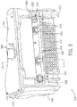
- a close up on a portion of the wire feeder 302 shows the power connections side panel 308 disposed above a vent strip 402 that is attached to an external housing 400 of the wire feeder 302.
- the external housing 400 protects interior components and further provides a handle 404 for aiding maneuverability.
- Both of the housing 400 and the handle 404 may be composed of lightweight, durable materials capable of withstanding shocks and weathering while maintaining the overall portability of the wire feeder 302. Such materials might include durable plastics, polycarbonate, carbon or aluminum alloys for the handle, and the like, and may be rugged in design.
- the housing may further provide labels indicative of the cable connections at the power connections side panel 308. As shown further in Fig.
- a cover (not shown) of the housing 400 may be lifted or detached to expose components within the housing 400, such as a spool 406 for receiving a reel of the consumable electrode wire (not shown) that is fed to the torch gun 326 during welding.
- the spool 406 may be mounted on a platform 408 or other component within or outside the housing 400.
- various attachment means for the components described herein may comprise permanent attachment means. manufactured as a single piece, adhesive, and the like, or detachable means, such as screws, snap action, friction fitting, and the like.
- the housing 400 may provide a sealing edge 410 configured to be disposed against the liftable or detachable cover (not shown) to prevent unwanted exposure of the interior to weather, insects, water, debris and the like.
- the sealing edge 410 might comprise rubber, foam, or other deformable materials having desirable characteristics for sealing applications.
- the power connections side panel 308 comprises four connectors configured to receive the four cables 310. 312, 314, 316 as described above.
- a work connector 412 comprising a female connector 414 is configured to receive the male connector end of the work cable 310.
- the female connector 414 may comprise any electrically conductive metallic hardware having a recessed hole that is constructed to receive an extending element of the male connector.
- Two power input connectors 416, 420 are provided for receiving the weld current from the remote power source 304. Each power input connectors 416, 420 comprises a male connector 418, 422, respectively, configured to receive the female connector end of a first or second weld cable 312, 314, respectively.
- the male connectors 418, 422 may comprise any electrically conductive metallic hardware having an extending conductive element that is configured to be received in a female connector.
- the male connectors 418. 422 as shown in the present embodiments are mounted directly onto the wire feeder 302.
- the present embodiment conforms by assigning the female connector 414 to the connector of cable 310 that outputs power, and the male connectors 418, 422 to the power input connectors 416, 420.
- any input or output functionality of the male or female connectors as shown shall not limit the scope of the present embodiments.
- the gas connector 424 may comprise a gas valve 426 protruding from the power connections side panel 308 that is configured to receive the gas cable 316 as described above.
- the gas valve 426 threadably engages a threaded outlet end of the gas cable 316, although various other connection means may apply.
- the gas connector 424 provides an orifice (not shown) aligned with a flow pathway of the gas cable 316 to convey the gas to the inside of the wire feeder 302, as required during the welding process.
- any or all of the four connectors 412. 436, 418. 424 may be mounted directly to a portion of the external housing 400 or to an interior housing, such as an electronics enclosure (see Fig. 4 ), that is disposed within the external housing 400.
- the four connectors 412, 416, 418, 424 may be aligned with a slot 428 on the housing 400 that exposes a portion of the interior housing in which the connectors 412, 416, 418, 424 are mounted. More particularly, the slot 428 may be provided on the power connections side panel 308 of the housing 400.
- the power connections side panel 308 refers to a portion of the wire feeder 302 in which the connectors 412. 416, 418, 424 are collectively displayed.
- the connectors 412, 416, 418, 424 may be placed in any order, and may represent one or any plurality of connectors.
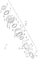
- a cross section taken along lines 4-4 of Fig. 3 shows the male connector 418 mounted directly onto an electronics housing 502 located within the wire feeder 302.
- the male connector 418 extends outwardly from the electronics housing 502 by securing to a coupling assembly 500, which comprises a bridging connector 504 received within a first bulkhead 506 that is further received within a second bulkhead 508.
- the second bulkhead 508 abuts a washer 510 and nut 512 arrangement that is secured proximate to an inside end 514 of the bridging connector 504, whereby said inside end 514 is further attached to a power bus bar 516.
- Opposing said inside end 514 on the bridging connector 504 is an outside end 518 having an upper and lower set screw orifice 520, 522, each orifice configured to align with a respective upper and lower set screw passage 524, 526 provided on the first bulkhead 506.
- One or both of corresponding pairs of set screw orifices 520, 522 and passages 524, 526 may be configured to receive a set screw 528, which impinges on a portion of the male connector 418 to prevent loosening of the connector 418 during thermal cycles and repeated connections and disconnections with the female connectors of the weld cables 312, 314.
- the coupling assembly 500 may be sealed from fluid or air by engaging a first o-ring 530 held between the bridging connector 504 and the first bulkhead 506, and a second o-ring 532 held between the first bulkhead 506 and the second bulkhead 508.
- the male connector 418 comprises a protruding element 534 extending to a threaded cylindrical shaft 536 that engages corresponding threads 538 proximate the outside end 518 of the bridging connector 504.
- the threaded engagement may be adjacent to the set screw orifices 520, 522. Together, the threaded engagement and the set screw 528 secure the male connector 418 onto the bridging connector 504.
- the male connector 418 further comprises a radial skirt 540 juxtaposed flush against the outside end 518 of the of the bridging connector 504. The radial skirl 540 may aid in positioning the male connector 418 onto the coupling assembly 500.
- the male connector 418 is constructed from an electrically conductive material, and may be designed in any variety of male threading, such as TWECO ® connectors, DlNSE ® connectors, quick-release mechanisms, and other standard or non-standard male connectors known in the art.
- the present embodiment utilizes a male connector having quick-release locking mechanism on the cylindrical protruding element 534, as described in further detail in Figs. 6A-6C .
- the coupling assembly 500 is adapted to retain a portion of a wall of the electronics housing 502 between two opposing surfaces of the first bulkhead 506 and the second bulkhead 508.
- the first bulkhead 506 includes an inner bulkhead segment 542 of lesser radial diameter extending to an outer bulkhead segment 544 of greater radial diameter.
- the inner bulkhead segment 542 is inserted within the second bulkhead 508.
- the outer bulkhead segment 544 abuts an outer surface of the electronics housing 502 underneath a housing protrusion 546.
- the second bulkhead 508 and the outer bulkhead segment 544 define the two opposing surfaces that cooperatively compress and secure the wall of the housing 502.
- the compressive force may be provided, at least in part, by the washer 510 and nut 512 threadably engaged onto the inside end 514 of the bridging connector 504 at surface threads 556.
- the nut 512 fixes the washer 510 flush against the second bulkhead 508 and pushes the second bulkhead 508 against the housing 502, while drawing inward the bridging connector 504 and the first bulkhead 506.
- a gasket 548 is provided between the second bulkhead 508 and the housing 502 so that fluid and dust are prevented from entering the housing 502.
- the above components of the coupling assembly 500 may comprise additional fitting or securing means, such as snap fitting, frictional fitting, deformation, lock and key mechanisms, etc., to engage the components together into assembly.
- Fig. 4 further shows the function of the bridging connector 504 which facilitates the electrical connection between the male connector 418 and the power bus bar 516.
- the power bus bar 516 may be coupled at the inside end 514 of the bridging connector 504.
- a threaded bolt 550 may fasten the bus bar 516 to the connector 504 having corresponding bridging threads 552 at the inside end 514.
- the bridging connector 504 is configured to join the coupling assembly 500 through the threaded boll 550 to the bus bar 516.
- different male connectors 418 may vary in the diameters of the threaded cylindrical shaft 536, such that a different bridging connector 504 may be configured to fit each type of male connector 418.
- the bridging connector 504 provides an electrical channel 554 between the male connector 418 and the bus bar 516 so that an electrical connection can be established and transferred to other components of the wire feeder 302.
- the male connector 418 comprises a protruding element 534 having a radial skirt 540 and extending to a threaded cylindrical shaft 536.
- the shaft 536 is received through the outside end 518 of the bridging connector 504 and threadably engaged to the interior corresponding threads 538 (see Fig. 4 ) of the connector 504.
- the connector 504 further provides the upper and lower set screw orifices 520, 522, one or more of which is configured to receive the set screw 528 that locks the male connector 418 into place.
- the inside end 514 of the bridging connector 504 is inserted through the first o-ring 530 and subsequently through the first bulkhead 506.
- the upper and lower set screw passages 524, 526 provided on the outer bulkhead segment 544 are configured to align with the upper and lower set screw orifices 520, 522 of the bridging connector 504. Note that although two set screw assemblies are shown, one or any plurality of set screw assemblies may be provided in the present embodiment.
- an inner surface of the second bulkhead 508 comprises a larger diameter than the outer diameter of the inner bulkhead segment 542, and in some cases, said inner diameter of the second bulkhead 508 is also larger than the outer diameter of the outer bulkhead segment 544, as illustrated in Fig. 4 .
- the second bulkhead 508 may provide two opposing flanges 602, 604 that are each indented with a notch 606 on an inner surface. Each notch 606 may be configured to receive a corresponding projection 608 on the first bulkhead 506 to aid in proper positioning and securing.
- the washer 510 and nut 512 assembly may be positioned behind the second bulkhead 508 and received on a portion of the bridging connector 504 proximal to its inside end 514.
- the washer 510 includes a plurality of internal teeth 610 that may prevent the preceding components and/or the nut 512 from backing out.
- the nut 512 may comprise a hexagonal nut having a threaded interior 612 for engaging the surface threads 556 provided on the bridging connector 504 (see Fig. 4 ).
- the components of the coupling assembly 500 are intended to be coaxially aligned and fitted together with the male connector 418.
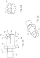
- Figs. 6A-6C illustrate one example of the male connector 418, which includes the cylindrical protruding element 534, or a first cylindrical portion, extending to the radial skirt 540 and further extending to the threaded cylindrical shaft 536, or a second cylindrical portion .
- the radial skirt 540 may be a hexagonally shaped skirt joined to a base end 702 of the protruding element 534 on an outer side 704 and a stem 708 on an inner side 706 of the skirt 540.
- the inner side 706 may comprise a substantially flat surface that is configured to abut a corresponding surface of the bridging connector 504, as described above.
- the stem 708 may extend to the threaded cylindrical shaft 536.
- any threading pattern may be utilized, such as a 1/2-13 UNC-2A, with the corresponding threads 538 of the bridging connector 504 fashioned in corresponding manner.
- the length of the threaded shaft 536 may be approximately 0.520-0.530 in.
- the threaded shaft 536 including the whole stem 708 may be 0.683-0,693 in.
- the threaded shaft 536 including the stem 708 and the whole radial skirt 540 may be 0.871-0.881 m.
- the length of the protruding element 534 may be approximately 0.925 in. long, such that it is slightly longer than the combined threaded shaft 536, stem 708, and radial skirt 540.
- the male connector 418 is approximately 1.801 in.
- the diameter of the protruding element 534 may be approximately 0.624 in., whereas the diameter of the stem 708 may be smaller around 0.395-0.405 in.
- the male connector 418 described above may be manufactured from a single piece of conductive metal, such as brass. Of course, these dimensions and configurations are for exemplary purposes only and are non-limiting.
- the protruding element 534 shown in Fig. 6A may be designed to have any variety of male threading, such as TWECO ® connectors, DINSE ® connectors, the Lenco Standard LC-40 Male connector, or other such connectors.
- the threading is quick-release designed which allows for fast engagement and disengagement with a female connector.
- the protruding element 534 includes according to the invention an arcuate face 710 having a generally circular surface area and curved downward on a conductive post 714.
- the arcuate face 710 is halved into two generally semicircular shapes by a radial trough 712 that extends across a centerpoint of the face 710 and longitudinally down through the conductive post 714 toward the base end 702.
- a longitudinal groove 716 is chipped from an outer surface of the conductive post 714 on an end near the arcuate face 710.
- the generally circular perimeter of the arcuate face 710 is interrupted by the longitudinal groove 716 that cuts into one semicircular portion of the arcuate face 710.
- annular channel 718 immediately behind the arcuate face 710 is an annular channel 718 extending from one side of the longitudinal groove 716.
- the channel 718 is carved into the conductive post 714 such that an annular ridge 720 is defined.
- the annular ridge 720 and the channel 718 span approximately a half ring around and behind the arcuate face 710, whereby a first end of the half ringlike channel 718 is deepest near the longitudinal groove 716.
- the channel 718 gradually becomes shallow as the second end of the half ringlike channel is approached at a ridge end 722 (see Fig. 6A ) approximately opposite the first end.
- the embodiment described herein provides a cam action mechanism for engaging to the female connector that generally comprises a hollow cylindrical tube having a wedge protruding from an interior surface of the tube.
- the wedge is initially aligned with the groove 716 and then rotated so that the wedge is received in the annular channel 718 behind the annular ridge 720.
- the radial trough 712 provides a linear spring action that contributes to a secure fit of the conductive post 714 within the female connector. The secure fit reduces electrical resistance and improves performance of the connection.
- the wedge is simply rotated back in line with the groove 716 and released. It is contemplated that rotation of the wedge, and therefore of the female connector, comprises approximately a half turn, and up to approximately a full turn, for engaging or disengaging from the male connector 418.
- the present invention includes a system for threadably engaging a male connector into a coupling assembly that is mounted directly onto the wire feeder.
- the advantages of the present embodiments are numerous.
- the machine-mounted male connectors minimize the overall size and bulk of the wire feeder to provide a less complex and more portable feeder.
- Direct mounting of the male connectors also substantially reduces the weight of wire feeder.
- the design further allows for easy replacement of the male connectors in the event they are worn, dirty or damaged. For instance, a worn male connector need only be unlocked by the set screw and unthreaded from the coupling assembly prior to threading in and locking a new male connector.
- the improved serviceability reduces downtime of the wire feeder.
- Direct mounting also reduces the damage susceptibility of the male connectors. which promotes improved performance.
Landscapes
- Engineering & Computer Science (AREA)
- Physics & Mathematics (AREA)
- Plasma & Fusion (AREA)
- Mechanical Engineering (AREA)
- Connector Housings Or Holding Contact Members (AREA)
- Manufacturing & Machinery (AREA)
- Details Of Connecting Devices For Male And Female Coupling (AREA)
Claims (9)
- Dispositif d'alimentation en fil (302) pour un système de soudage (300), comprenant :- une source d'alimentation en fil configurée pour délivrer un fil-électrode consommable à un chalumeau de soudage (326) durant un processus de soudage ;- un boîtier (400) s'étendant autour d'au moins une partie du dispositif d'alimentation en fil (302) ;- une unité de connexion d'énergie configurée pour transférer l'énergie reçue à partir d'une source d'énergie (304) durant le processus de soudage, l'unité de connexion d'énergie comprenant :dans lequel l'unité de connexion d'énergie est au moins partiellement agencée à l'intérieur du boîtier (400) et comprend- une entrée configurée pour recevoir de l'énergie à partir de la source d'énergie (304) ;- une sortie configurée pour délivrer l'énergie reçue sur l'entrée pour conduire le processus de soudage ;- un système de bus, configuré pour connecter l'entrée et la sortie ;un connecteur mâle (418, 422) ayant un montant conducteur (714) s'étendant vers un arbre cylindrique fileté (536), le connecteur mâle formant au moins une partie d'au moins une parmi l'entrée et la sortie et s'étendant à partir du boîtier (400) à travers un ensemble de couplage (500), dans lequel l'ensemble de couplage (500) comprend une partie filetée de manière correspondante (538) configurée pour s'engager avec l'arbre cylindrique fileté (536) du connecteur mâle (418, 422) au système de bus,caractérisé en ce quele montant conducteur (714) comprend un mécanisme d'action de came pour s'engager avec un connecteur de réception, dans lequel le connecteur mâle (418, 422) comprend une face arquée (710) ayant une surface généralement circulaire et incurvée vers le bas sur le montant conducteur (714), dans lequel la face arquée (710) est divisée en deux parties généralement semi-circulaires par un creux radial (712) qui s'étend à travers un point central de la face (710) et longitudinalement vers le bas à travers le montant conducteur (714) vers une extrémité de base (702), dans lequel le périmètre généralement circulaire de la face arquée (710) est interrompu par une rainure longitudinale (716) qui se découpe dans une partie semi-circulaire de la face arquée (710), dans lequel un canal annulaire (718) s'étend immédiatement derrière la face arquée (710) à partir d'un côté de la rainure longitudinale (716) gravée dans le montant conducteur (714) de sorte qu'une nervure annulaire (720) est définie, dans lequel la nervure annulaire (720) et le canal (718) couvrent approximativement un demi-anneau autour et derrière la face arquée (710), moyennant quoi une première extrémité du canal (718) est la plus profonde près de la rainure longitudinale (716), et le canal (718) devient peu profond au fur et à mesure que la deuxième extrémité du canal semi-annulaire est approchée à une extrémité de crête (722) approximativement à l'opposé de la première extrémité.
- Dispositif d'alimentation en fil selon la revendication 1, comprenant en outre une vis de réglage (528) configurée pour fixer en outre le connecteur mâle (418, 422) à l'ensemble de couplage (500).
- Dispositif d'alimentation en fil selon l'une des revendications 1 ou 2,dans lequel l'ensemble de couplage (500) comprend en outre au moins une tête de boulonnage (506, 508), et/oudans lequel l'ensemble de couplage (500) comprend en outre au moins un joint torique (530, 532), et/oudans lequel l'ensemble de couplage (500) comprend en outre au moins un ensemble de rondelle (510) et d'écrou (512).
- Dispositif d'alimentation en fil selon l'une quelconque des revendications précédentes,
comprenant en outre un boîtier électronique (502) disposé à l'intérieur du boîtier (400) et entourant le système de bus et dans lequel l'ensemble de couplage (500) est configuré pour recevoir et fixer au moins un parmi le boîtier (400) et une partie du boîtier électronique (502). - Dispositif d'alimentation en fil selon l'une quelconque des revendications précédentes,
dans lequel une partie de l'ensemble de couplage (500) s'étend à travers le boîtier (400). - Dispositif d'alimentation en fil selon l'une quelconque des revendications précédentes,
dans lequel le système de bus comprend une barre omnibus (516) configurée pour réaliser une connexion électrique entre l'entrée et la sortie et dans lequel l'ensemble de couplage (500) est fixé à la barre omnibus disposée à l'intérieur du boîtier (400). - Dispositif d'alimentation en fil selon l'une quelconque des revendications précédentes,
dans lequel l'ensemble de couplage (500) comprend en outre un joint (548) configuré pour sceller l'ensemble de couplage (500). - Dispositif d'alimentation en fil selon l'une quelconque des revendications précédentes,
dans lequel le boîtier (400) est construit en plastique et comprend au moins une poignée (404). - Système de soudage, comprenant :- un chalumeau de soudage (326) ;- une source d'énergie (304) configurée pour délivrer de l'énergie au chalumeau de soudage (326) pour réaliser un processus de soudage ; et- dispositif d'alimentation en fil (302) selon l'une quelconque des revendications précédentes, configuré pour délivrer un fil-électrode consommable au chalumeau de soudage (326) durant le processus de soudage.
Applications Claiming Priority (2)
| Application Number | Priority Date | Filing Date | Title |
|---|---|---|---|
| US13/793,391 US9314867B2 (en) | 2013-03-11 | 2013-03-11 | Replaceable machine-mounted male input power connections |
| PCT/US2014/015645 WO2014163762A1 (fr) | 2013-03-11 | 2014-02-10 | Connexions électriques remplaçables d'entrée mâle montées sur une machine |
Publications (2)
| Publication Number | Publication Date |
|---|---|
| EP2969352A1 EP2969352A1 (fr) | 2016-01-20 |
| EP2969352B1 true EP2969352B1 (fr) | 2022-12-14 |
Family
ID=50189770
Family Applications (1)
| Application Number | Title | Priority Date | Filing Date |
|---|---|---|---|
| EP14707275.5A Active EP2969352B1 (fr) | 2013-03-11 | 2014-02-10 | Connexions électriques remplaçables d'entrée mâle montées sur une machine |
Country Status (5)
| Country | Link |
|---|---|
| US (2) | US9314867B2 (fr) |
| EP (1) | EP2969352B1 (fr) |
| CN (1) | CN105073325B (fr) |
| CA (1) | CA2896823C (fr) |
| WO (1) | WO2014163762A1 (fr) |
Families Citing this family (14)
| Publication number | Priority date | Publication date | Assignee | Title |
|---|---|---|---|---|
| US20170080510A1 (en) * | 2015-09-18 | 2017-03-23 | Illinois Tool Works Inc. | Contact tip and coupling assembly of a welding torch |
| US10583514B2 (en) * | 2015-09-18 | 2020-03-10 | Illinois Tool Works Inc. | Contact tip rotary lock of a welding torch |
| US10773332B2 (en) * | 2015-09-18 | 2020-09-15 | Illinois Tool Works Inc. | Contact tip and receiving assembly of a welding torch |
| US20170136566A1 (en) * | 2015-11-17 | 2017-05-18 | Illinois Tool Works Inc. | Power interconnects in a modular access panel |
| US20180050415A1 (en) * | 2016-08-16 | 2018-02-22 | Lincoln Global, Inc. | Torch quick release mechanism |
| US10882133B2 (en) | 2017-01-31 | 2021-01-05 | Illinois Tool Works Inc. | Tip-retention device for use with a welding system |
| US11103949B2 (en) | 2017-04-03 | 2021-08-31 | Illinois Tool Works Inc. | Quick connect configurations for welding necks and gas diffusers |
| US11938573B2 (en) | 2017-04-19 | 2024-03-26 | Illlinois Tool Works Inc. | Welding systems for cooling welding contact tips |
| DE202018100964U1 (de) * | 2018-02-21 | 2019-05-23 | Weidmüller Interface GmbH & Co. KG | Kontakt- und Busschienenanordnung |
| US11894642B2 (en) * | 2018-07-12 | 2024-02-06 | Illinois Tool Works Inc. | Reconfigurable welding-type power sockets and power plugs |
| US11705774B2 (en) * | 2018-12-27 | 2023-07-18 | Abb Schweiz Ag | Industrial electrical machine system and electronics module |
| US11211721B2 (en) * | 2020-03-19 | 2021-12-28 | Lear Corporation | Threaded stud within a conductive bushing connecting a printed circuit board |
| CN114204376B (zh) * | 2021-12-02 | 2024-01-23 | 杭州中芯微电子有限公司 | 一种用于通讯网关设备连接网线连接器镀金针脚排列切割设备 |
| CN114406545B (zh) * | 2022-02-17 | 2023-12-08 | 洛阳理工学院 | 一种滑动式车身焊装定位销工作台 |
Citations (2)
| Publication number | Priority date | Publication date | Assignee | Title |
|---|---|---|---|---|
| CH670210A5 (en) * | 1986-05-02 | 1989-05-31 | Mechafin Ag | Welding torch connecting coupling - with two insulating plastic halves joined by plastic union nut |
| EP1638171A2 (fr) * | 2004-09-21 | 2006-03-22 | Illinois Tool Works Inc. | Connecteur rapide électrique à haute puissance |
Family Cites Families (6)
| Publication number | Priority date | Publication date | Assignee | Title |
|---|---|---|---|---|
| US5902150A (en) | 1997-01-09 | 1999-05-11 | Illinois Tool Works Inc | Connector for a power supply |
| HU223861B1 (hu) * | 1999-06-14 | 2005-02-28 | Antal Natta | Csatlakozó hegesztőpisztoly csatlakoztatásához |
| US6309231B1 (en) * | 1999-09-02 | 2001-10-30 | Litton Precision Products International, Inc. | High current male and female power connector assembly |
| US7204709B2 (en) * | 2003-07-15 | 2007-04-17 | Lincoln Global, Inc. | Cable connector for welder or wire feeder |
| US7624908B2 (en) * | 2005-08-17 | 2009-12-01 | Lincoln Global, Inc. | Welding wire feeder and connection apparatus |
| US8847116B2 (en) * | 2006-06-12 | 2014-09-30 | Victor Equipment Company | Wire feeder with interchangeable adaptor cartridges |
-
2013
- 2013-03-11 US US13/793,391 patent/US9314867B2/en active Active
-
2014
- 2014-02-10 WO PCT/US2014/015645 patent/WO2014163762A1/fr not_active Ceased
- 2014-02-10 CA CA2896823A patent/CA2896823C/fr active Active
- 2014-02-10 EP EP14707275.5A patent/EP2969352B1/fr active Active
- 2014-02-10 CN CN201480011967.8A patent/CN105073325B/zh active Active
-
2016
- 2016-01-12 US US14/993,199 patent/US9782851B2/en active Active
Patent Citations (2)
| Publication number | Priority date | Publication date | Assignee | Title |
|---|---|---|---|---|
| CH670210A5 (en) * | 1986-05-02 | 1989-05-31 | Mechafin Ag | Welding torch connecting coupling - with two insulating plastic halves joined by plastic union nut |
| EP1638171A2 (fr) * | 2004-09-21 | 2006-03-22 | Illinois Tool Works Inc. | Connecteur rapide électrique à haute puissance |
Also Published As
| Publication number | Publication date |
|---|---|
| CN105073325A (zh) | 2015-11-18 |
| CA2896823A1 (fr) | 2014-10-09 |
| EP2969352A1 (fr) | 2016-01-20 |
| US20140251972A1 (en) | 2014-09-11 |
| US9314867B2 (en) | 2016-04-19 |
| US9782851B2 (en) | 2017-10-10 |
| WO2014163762A1 (fr) | 2014-10-09 |
| CN105073325B (zh) | 2018-10-02 |
| CA2896823C (fr) | 2020-08-25 |
| US20160121419A1 (en) | 2016-05-05 |
Similar Documents
| Publication | Publication Date | Title |
|---|---|---|
| EP2969352B1 (fr) | Connexions électriques remplaçables d'entrée mâle montées sur une machine | |
| US8426773B2 (en) | Dual power pin connector assembly for a MIG welding machine | |
| US9040868B2 (en) | Plasma torch and retaining cap with fast securing threads | |
| US20250281992A1 (en) | Quick connect configurations for welding necks and gas diffusers | |
| KR101412374B1 (ko) | 용접토치 및 그 조립방법 | |
| US12394950B2 (en) | Reconfigurable welding-type power sockets and power plugs | |
| US5866874A (en) | Robotic welding torch and method of assembly | |
| CN107848060B (zh) | 适于将等离子割炬连接到发生器的连接系统 | |
| US12076825B2 (en) | Welding process wire feeder adapter insulator | |
| JPS6074368A (ja) | 旋回継手 | |
| JP2018027569A (ja) | トーチクイックリリース機構 | |
| US7294809B2 (en) | Configurable securing assembly for neck of welding gun | |
| US10328515B2 (en) | Neck for a welding gun | |
| US12558736B2 (en) | Modular quick disconnect system for welding and cutting systems and method of making | |
| CA2485302A1 (fr) | Cable d'alimentation a double role avec porte-torche pour le soudage avec electrodes de tungstene et porte-electrodes pour le soudage avec electrodes enrobees interchangeables | |
| KR101070512B1 (ko) | 자체 보호 플럭스 코어드 와이어를 이용한 플럭스 코어드 아크 용접용 토치 장치 | |
| KR200469758Y1 (ko) | 용접용 케이블 커넥터 | |
| JPH0899174A (ja) | アーク溶接用ロボット | |
| US20240391015A1 (en) | Quick-change cables and welding torch systems having quick-change cables | |
| US20240396277A1 (en) | Rotating power connector for welding torch cables |
Legal Events
| Date | Code | Title | Description |
|---|---|---|---|
| PUAI | Public reference made under article 153(3) epc to a published international application that has entered the european phase |
Free format text: ORIGINAL CODE: 0009012 |
|
| 17P | Request for examination filed |
Effective date: 20150702 |
|
| AK | Designated contracting states |
Kind code of ref document: A1 Designated state(s): AL AT BE BG CH CY CZ DE DK EE ES FI FR GB GR HR HU IE IS IT LI LT LU LV MC MK MT NL NO PL PT RO RS SE SI SK SM TR |
|
| AX | Request for extension of the european patent |
Extension state: BA ME |
|
| DAX | Request for extension of the european patent (deleted) | ||
| STAA | Information on the status of an ep patent application or granted ep patent |
Free format text: STATUS: EXAMINATION IS IN PROGRESS |
|
| 17Q | First examination report despatched |
Effective date: 20180409 |
|
| GRAP | Despatch of communication of intention to grant a patent |
Free format text: ORIGINAL CODE: EPIDOSNIGR1 |
|
| STAA | Information on the status of an ep patent application or granted ep patent |
Free format text: STATUS: GRANT OF PATENT IS INTENDED |
|
| INTG | Intention to grant announced |
Effective date: 20220701 |
|
| GRAS | Grant fee paid |
Free format text: ORIGINAL CODE: EPIDOSNIGR3 |
|
| GRAA | (expected) grant |
Free format text: ORIGINAL CODE: 0009210 |
|
| STAA | Information on the status of an ep patent application or granted ep patent |
Free format text: STATUS: THE PATENT HAS BEEN GRANTED |
|
| AK | Designated contracting states |
Kind code of ref document: B1 Designated state(s): AL AT BE BG CH CY CZ DE DK EE ES FI FR GB GR HR HU IE IS IT LI LT LU LV MC MK MT NL NO PL PT RO RS SE SI SK SM TR |
|
| REG | Reference to a national code |
Ref country code: GB Ref legal event code: FG4D |
|
| REG | Reference to a national code |
Ref country code: CH Ref legal event code: EP |
|
| REG | Reference to a national code |
Ref country code: DE Ref legal event code: R096 Ref document number: 602014085781 Country of ref document: DE |
|
| REG | Reference to a national code |
Ref country code: IE Ref legal event code: FG4D |
|
| REG | Reference to a national code |
Ref country code: AT Ref legal event code: REF Ref document number: 1537385 Country of ref document: AT Kind code of ref document: T Effective date: 20230115 |
|
| REG | Reference to a national code |
Ref country code: LT Ref legal event code: MG9D |
|
| REG | Reference to a national code |
Ref country code: NL Ref legal event code: MP Effective date: 20221214 |
|
| PG25 | Lapsed in a contracting state [announced via postgrant information from national office to epo] |
Ref country code: SE Free format text: LAPSE BECAUSE OF FAILURE TO SUBMIT A TRANSLATION OF THE DESCRIPTION OR TO PAY THE FEE WITHIN THE PRESCRIBED TIME-LIMIT Effective date: 20221214 Ref country code: NO Free format text: LAPSE BECAUSE OF FAILURE TO SUBMIT A TRANSLATION OF THE DESCRIPTION OR TO PAY THE FEE WITHIN THE PRESCRIBED TIME-LIMIT Effective date: 20230314 Ref country code: LT Free format text: LAPSE BECAUSE OF FAILURE TO SUBMIT A TRANSLATION OF THE DESCRIPTION OR TO PAY THE FEE WITHIN THE PRESCRIBED TIME-LIMIT Effective date: 20221214 Ref country code: FI Free format text: LAPSE BECAUSE OF FAILURE TO SUBMIT A TRANSLATION OF THE DESCRIPTION OR TO PAY THE FEE WITHIN THE PRESCRIBED TIME-LIMIT Effective date: 20221214 |
|
| REG | Reference to a national code |
Ref country code: AT Ref legal event code: MK05 Ref document number: 1537385 Country of ref document: AT Kind code of ref document: T Effective date: 20221214 |
|
| PG25 | Lapsed in a contracting state [announced via postgrant information from national office to epo] |
Ref country code: RS Free format text: LAPSE BECAUSE OF FAILURE TO SUBMIT A TRANSLATION OF THE DESCRIPTION OR TO PAY THE FEE WITHIN THE PRESCRIBED TIME-LIMIT Effective date: 20221214 Ref country code: LV Free format text: LAPSE BECAUSE OF FAILURE TO SUBMIT A TRANSLATION OF THE DESCRIPTION OR TO PAY THE FEE WITHIN THE PRESCRIBED TIME-LIMIT Effective date: 20221214 Ref country code: HR Free format text: LAPSE BECAUSE OF FAILURE TO SUBMIT A TRANSLATION OF THE DESCRIPTION OR TO PAY THE FEE WITHIN THE PRESCRIBED TIME-LIMIT Effective date: 20221214 Ref country code: GR Free format text: LAPSE BECAUSE OF FAILURE TO SUBMIT A TRANSLATION OF THE DESCRIPTION OR TO PAY THE FEE WITHIN THE PRESCRIBED TIME-LIMIT Effective date: 20230315 |
|
| PG25 | Lapsed in a contracting state [announced via postgrant information from national office to epo] |
Ref country code: NL Free format text: LAPSE BECAUSE OF FAILURE TO SUBMIT A TRANSLATION OF THE DESCRIPTION OR TO PAY THE FEE WITHIN THE PRESCRIBED TIME-LIMIT Effective date: 20221214 |
|
| P01 | Opt-out of the competence of the unified patent court (upc) registered |
Effective date: 20230606 |
|
| PG25 | Lapsed in a contracting state [announced via postgrant information from national office to epo] |
Ref country code: SM Free format text: LAPSE BECAUSE OF FAILURE TO SUBMIT A TRANSLATION OF THE DESCRIPTION OR TO PAY THE FEE WITHIN THE PRESCRIBED TIME-LIMIT Effective date: 20221214 Ref country code: RO Free format text: LAPSE BECAUSE OF FAILURE TO SUBMIT A TRANSLATION OF THE DESCRIPTION OR TO PAY THE FEE WITHIN THE PRESCRIBED TIME-LIMIT Effective date: 20221214 Ref country code: PT Free format text: LAPSE BECAUSE OF FAILURE TO SUBMIT A TRANSLATION OF THE DESCRIPTION OR TO PAY THE FEE WITHIN THE PRESCRIBED TIME-LIMIT Effective date: 20230414 Ref country code: ES Free format text: LAPSE BECAUSE OF FAILURE TO SUBMIT A TRANSLATION OF THE DESCRIPTION OR TO PAY THE FEE WITHIN THE PRESCRIBED TIME-LIMIT Effective date: 20221214 Ref country code: EE Free format text: LAPSE BECAUSE OF FAILURE TO SUBMIT A TRANSLATION OF THE DESCRIPTION OR TO PAY THE FEE WITHIN THE PRESCRIBED TIME-LIMIT Effective date: 20221214 Ref country code: CZ Free format text: LAPSE BECAUSE OF FAILURE TO SUBMIT A TRANSLATION OF THE DESCRIPTION OR TO PAY THE FEE WITHIN THE PRESCRIBED TIME-LIMIT Effective date: 20221214 Ref country code: AT Free format text: LAPSE BECAUSE OF FAILURE TO SUBMIT A TRANSLATION OF THE DESCRIPTION OR TO PAY THE FEE WITHIN THE PRESCRIBED TIME-LIMIT Effective date: 20221214 |
|
| PG25 | Lapsed in a contracting state [announced via postgrant information from national office to epo] |
Ref country code: SK Free format text: LAPSE BECAUSE OF FAILURE TO SUBMIT A TRANSLATION OF THE DESCRIPTION OR TO PAY THE FEE WITHIN THE PRESCRIBED TIME-LIMIT Effective date: 20221214 Ref country code: PL Free format text: LAPSE BECAUSE OF FAILURE TO SUBMIT A TRANSLATION OF THE DESCRIPTION OR TO PAY THE FEE WITHIN THE PRESCRIBED TIME-LIMIT Effective date: 20221214 Ref country code: IS Free format text: LAPSE BECAUSE OF FAILURE TO SUBMIT A TRANSLATION OF THE DESCRIPTION OR TO PAY THE FEE WITHIN THE PRESCRIBED TIME-LIMIT Effective date: 20230414 Ref country code: AL Free format text: LAPSE BECAUSE OF FAILURE TO SUBMIT A TRANSLATION OF THE DESCRIPTION OR TO PAY THE FEE WITHIN THE PRESCRIBED TIME-LIMIT Effective date: 20221214 |
|
| REG | Reference to a national code |
Ref country code: DE Ref legal event code: R097 Ref document number: 602014085781 Country of ref document: DE |
|
| PG25 | Lapsed in a contracting state [announced via postgrant information from national office to epo] |
Ref country code: MC Free format text: LAPSE BECAUSE OF FAILURE TO SUBMIT A TRANSLATION OF THE DESCRIPTION OR TO PAY THE FEE WITHIN THE PRESCRIBED TIME-LIMIT Effective date: 20221214 |
|
| REG | Reference to a national code |
Ref country code: CH Ref legal event code: PL |
|
| REG | Reference to a national code |
Ref country code: BE Ref legal event code: MM Effective date: 20230228 |
|
| PLBE | No opposition filed within time limit |
Free format text: ORIGINAL CODE: 0009261 |
|
| STAA | Information on the status of an ep patent application or granted ep patent |
Free format text: STATUS: NO OPPOSITION FILED WITHIN TIME LIMIT |
|
| PG25 | Lapsed in a contracting state [announced via postgrant information from national office to epo] |
Ref country code: LU Free format text: LAPSE BECAUSE OF NON-PAYMENT OF DUE FEES Effective date: 20230210 Ref country code: LI Free format text: LAPSE BECAUSE OF NON-PAYMENT OF DUE FEES Effective date: 20230228 Ref country code: DK Free format text: LAPSE BECAUSE OF FAILURE TO SUBMIT A TRANSLATION OF THE DESCRIPTION OR TO PAY THE FEE WITHIN THE PRESCRIBED TIME-LIMIT Effective date: 20221214 Ref country code: CH Free format text: LAPSE BECAUSE OF NON-PAYMENT OF DUE FEES Effective date: 20230228 |
|
| 26N | No opposition filed |
Effective date: 20230915 |
|
| GBPC | Gb: european patent ceased through non-payment of renewal fee |
Effective date: 20230314 |
|
| PG25 | Lapsed in a contracting state [announced via postgrant information from national office to epo] |
Ref country code: SI Free format text: LAPSE BECAUSE OF FAILURE TO SUBMIT A TRANSLATION OF THE DESCRIPTION OR TO PAY THE FEE WITHIN THE PRESCRIBED TIME-LIMIT Effective date: 20221214 |
|
| REG | Reference to a national code |
Ref country code: IE Ref legal event code: MM4A |
|
| PG25 | Lapsed in a contracting state [announced via postgrant information from national office to epo] |
Ref country code: GB Free format text: LAPSE BECAUSE OF NON-PAYMENT OF DUE FEES Effective date: 20230314 |
|
| PG25 | Lapsed in a contracting state [announced via postgrant information from national office to epo] |
Ref country code: IE Free format text: LAPSE BECAUSE OF NON-PAYMENT OF DUE FEES Effective date: 20230210 Ref country code: GB Free format text: LAPSE BECAUSE OF NON-PAYMENT OF DUE FEES Effective date: 20230314 Ref country code: FR Free format text: LAPSE BECAUSE OF NON-PAYMENT OF DUE FEES Effective date: 20230214 |
|
| PG25 | Lapsed in a contracting state [announced via postgrant information from national office to epo] |
Ref country code: BE Free format text: LAPSE BECAUSE OF NON-PAYMENT OF DUE FEES Effective date: 20230228 |
|
| PG25 | Lapsed in a contracting state [announced via postgrant information from national office to epo] |
Ref country code: BG Free format text: LAPSE BECAUSE OF FAILURE TO SUBMIT A TRANSLATION OF THE DESCRIPTION OR TO PAY THE FEE WITHIN THE PRESCRIBED TIME-LIMIT Effective date: 20221214 |
|
| PG25 | Lapsed in a contracting state [announced via postgrant information from national office to epo] |
Ref country code: BG Free format text: LAPSE BECAUSE OF FAILURE TO SUBMIT A TRANSLATION OF THE DESCRIPTION OR TO PAY THE FEE WITHIN THE PRESCRIBED TIME-LIMIT Effective date: 20221214 |
|
| PG25 | Lapsed in a contracting state [announced via postgrant information from national office to epo] |
Ref country code: CY Free format text: LAPSE BECAUSE OF FAILURE TO SUBMIT A TRANSLATION OF THE DESCRIPTION OR TO PAY THE FEE WITHIN THE PRESCRIBED TIME-LIMIT; INVALID AB INITIO Effective date: 20140210 |
|
| PG25 | Lapsed in a contracting state [announced via postgrant information from national office to epo] |
Ref country code: HU Free format text: LAPSE BECAUSE OF FAILURE TO SUBMIT A TRANSLATION OF THE DESCRIPTION OR TO PAY THE FEE WITHIN THE PRESCRIBED TIME-LIMIT; INVALID AB INITIO Effective date: 20140210 |
|
| PG25 | Lapsed in a contracting state [announced via postgrant information from national office to epo] |
Ref country code: TR Free format text: LAPSE BECAUSE OF FAILURE TO SUBMIT A TRANSLATION OF THE DESCRIPTION OR TO PAY THE FEE WITHIN THE PRESCRIBED TIME-LIMIT Effective date: 20221214 |
|
| PGFP | Annual fee paid to national office [announced via postgrant information from national office to epo] |
Ref country code: DE Payment date: 20260227 Year of fee payment: 13 |
|
| PGFP | Annual fee paid to national office [announced via postgrant information from national office to epo] |
Ref country code: IT Payment date: 20260219 Year of fee payment: 13 |