EP2969384B1 - Dykes-kolbenringe und verfahren zur herstellung davon - Google Patents
Dykes-kolbenringe und verfahren zur herstellung davon Download PDFInfo
- Publication number
- EP2969384B1 EP2969384B1 EP14711380.7A EP14711380A EP2969384B1 EP 2969384 B1 EP2969384 B1 EP 2969384B1 EP 14711380 A EP14711380 A EP 14711380A EP 2969384 B1 EP2969384 B1 EP 2969384B1
- Authority
- EP
- European Patent Office
- Prior art keywords
- stock bar
- machining
- piston ring
- section
- outer diameter
- Prior art date
- Legal status (The legal status is an assumption and is not a legal conclusion. Google has not performed a legal analysis and makes no representation as to the accuracy of the status listed.)
- Not-in-force
Links
Images
Classifications
-
- F—MECHANICAL ENGINEERING; LIGHTING; HEATING; WEAPONS; BLASTING
- F16—ENGINEERING ELEMENTS AND UNITS; GENERAL MEASURES FOR PRODUCING AND MAINTAINING EFFECTIVE FUNCTIONING OF MACHINES OR INSTALLATIONS; THERMAL INSULATION IN GENERAL
- F16J—PISTONS; CYLINDERS; SEALINGS
- F16J9/00—Piston-rings, e.g. non-metallic piston-rings, seats therefor; Ring sealings of similar construction
- F16J9/02—L-section rings
-
- B—PERFORMING OPERATIONS; TRANSPORTING
- B23—MACHINE TOOLS; METAL-WORKING NOT OTHERWISE PROVIDED FOR
- B23P—METAL-WORKING NOT OTHERWISE PROVIDED FOR; COMBINED OPERATIONS; UNIVERSAL MACHINE TOOLS
- B23P15/00—Making specific metal objects by operations not covered by a single other subclass or a group in this subclass
- B23P15/06—Making specific metal objects by operations not covered by a single other subclass or a group in this subclass piston rings from one piece
-
- B—PERFORMING OPERATIONS; TRANSPORTING
- B23—MACHINE TOOLS; METAL-WORKING NOT OTHERWISE PROVIDED FOR
- B23P—METAL-WORKING NOT OTHERWISE PROVIDED FOR; COMBINED OPERATIONS; UNIVERSAL MACHINE TOOLS
- B23P15/00—Making specific metal objects by operations not covered by a single other subclass or a group in this subclass
- B23P15/06—Making specific metal objects by operations not covered by a single other subclass or a group in this subclass piston rings from one piece
- B23P15/065—Making specific metal objects by operations not covered by a single other subclass or a group in this subclass piston rings from one piece from metal strip
-
- F—MECHANICAL ENGINEERING; LIGHTING; HEATING; WEAPONS; BLASTING
- F16—ENGINEERING ELEMENTS AND UNITS; GENERAL MEASURES FOR PRODUCING AND MAINTAINING EFFECTIVE FUNCTIONING OF MACHINES OR INSTALLATIONS; THERMAL INSULATION IN GENERAL
- F16J—PISTONS; CYLINDERS; SEALINGS
- F16J9/00—Piston-rings, e.g. non-metallic piston-rings, seats therefor; Ring sealings of similar construction
- F16J9/12—Details
- F16J9/14—Joint-closures
-
- Y—GENERAL TAGGING OF NEW TECHNOLOGICAL DEVELOPMENTS; GENERAL TAGGING OF CROSS-SECTIONAL TECHNOLOGIES SPANNING OVER SEVERAL SECTIONS OF THE IPC; TECHNICAL SUBJECTS COVERED BY FORMER USPC CROSS-REFERENCE ART COLLECTIONS [XRACs] AND DIGESTS
- Y10—TECHNICAL SUBJECTS COVERED BY FORMER USPC
- Y10T—TECHNICAL SUBJECTS COVERED BY FORMER US CLASSIFICATION
- Y10T29/00—Metal working
- Y10T29/49—Method of mechanical manufacture
- Y10T29/49229—Prime mover or fluid pump making
- Y10T29/49274—Piston ring or piston packing making
- Y10T29/49284—Piston ring or piston packing making including machining or angular cutting
Definitions
- the subject invention provides a method for manufacturing a low tension piston ring, specifically a dykes-type piston ring having a finished outer diameter and negligible tangential tension.
- Piston rings are a critical component of an internal combustion engine.
- the engine includes at least one cylinder and piston.
- Piston rings are metallic seals disposed between the cylinder wall and the piston to seal the combustion chamber from the crankcase and facilitate heat transfer from the piston to the cylinder.
- Other functions of piston rings are to prevent the oil not needed for lubrication from passing from the crankcase to the combustion chamber and to provide a uniform oil film on the cylinder bore surface. To achieve this, the piston rings must remain in contact with the cylinder and the piston. Radial contact is generally achieved by means of the inherent spring force of the piston ring.
- Piston rings are also employed as metallic seals for rotating shafts and are used both as contracting and expanding seals.
- piston rings are typically manufactured in one of two ways.
- the piston rings are cast as individual rings in a noncircular shape.
- Such rings are then typically machined to the required shape by means of double cam turning, a process in which the ring blank, already axially ground, is cam turned simultaneously on the inside and outside diameters. After a segment equivalent to the free gap is cut from the piston ring, it assumes the free shape that will give it the required radial pressure distribution when fitted into the cylinder. Once inside the cylinder, the piston ring exerts the predefined radial pressure against the cylinder wall.
- ring blanks may also be shaped by machining the inside and outside diameters separately. This involves cam turning the outside diameter of the noncircular blank and machining the inside diameter with the piston ring in the compressed state. The free gap is cut out in a step between the outer diameter and inner diameter machining.
- steel piston rings are made from a profiled wire.
- the rings are first coiled into a circular shape and then the gap is cut out.
- the necessary shape is obtained using a heat treatment process in which the rings are mounted onto an arbor appropriately designed to impart the required radial pressure distribution.
- Profiling of the outer diameter is carried out, depending on the piston ring design, on automatic outer diameter lathes or profile grinding machines using profile cutting tools.
- piston rings are produced with residual tangential tension.
- Production of piston rings with residual tangential tension is problematic because such piston rings have a tendency to twist or warp.
- Such ring twist or warp may lead to excessive oil consumption and blow-by, a condition where combustion gasses escape from the combustion chamber by passing along the piston between the piston rings and the cylinder wall.
- piston rings with residual tangential tension may adversely affect the efficiency, the performance, the emissions, and/or the reliability of the engine.
- One such method includes the step of heat treating a stock bar made of cast iron at a high temperature, for example 1100° Fahrenheit (593.33° Celsius), to remove foundry strains and hard spots. After the stock bar is heat treated, piston ring blanks are cut from the stock bar. Once the piston ring blanks are detached from the stock bar, the method continues with the steps of conventional machining and finishing the piston ring blank to final outer and inner diameters. The last step is cutting a final free gap into the piston ring. Although this method produces rings having less of a tendency to twist or warp, significant tangential tension still remains in the piston rings.
- Dykes type piston rings allow for better sealing at higher engine speeds and combustion pressures.
- the asymmetrical shape of the dykes type piston ring results in a piston ring that is more prone to twist or warp than conventional piston rings. Accordingly, there is a need for piston rings, particularly dykes-type piston rings with negligible tangential tension.
- GB 2 239 926 A relates to a method of manufacturing piston rings where the piston rings are individually detached from a tube.
- US 4,346,685 A relates to L-shaped piston rings.
- the invention is defined by claim 1.
- a piston ring is detached from a stock bar using a parting tool after completing all tension inducing operations including the steps of machining the stock bar to the initial outer diameter, finishing the stock bar to a predetermined profile, and machining the stock bar to a predetermined cross-section.
- the piston ring is not separated from the stock bar until after all of the machining and finishing steps have been completed. In this manner, the stresses associated with the machining and finishing operations are borne by the thicker stock bar before the piston ring is separated.
- the subject invention can provide a dykes-type piston ring including an annular ring body having a measurable tangential tension ranging from zero to 25 Newtons in a free and uncompressed state.
- the dykes type piston ring defines a final gap having a gap width measurable between a pair of lateral faces ranging from zero to 0.4 millimeters when the annular ring body is in its free and uncompressed state.
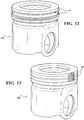
- Figure 12 illustrates a conventional piston 100 with traditional piston rings 18 mounted on it.
- Figure 13 illustrates a piston 200 with dykes-type piston rings 20 positioned on it.
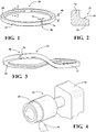
- a dykes-type piston ring 20 having a finished outer diameter is presented. It should be appreciated that the piston ring 20 is circular in shape and has a circumference 24 . The finished outer diameter extends along the circumference 24 .
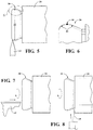
- a preferred method embodiment of the subject invention is shown in Figures 4-6 .
- the method includes the steps of machining a stock bar 26 to an initial outer diameter 28 slightly greater than the finished outer diameter of the piston ring 20 , finishing the initial outer diameter of the stock bar 26 to a predetermined profile 30 having a nominal diameter 32 .
- the diameter 32 is equal to the finished outer diameter 22 .
- the stock bar 26 is also machined to form a structure with an L-shaped cross-section.
- the method continues with the step of detaching the piston ring 20 from the stock bar 26 in response to completing all tension inducing operations including the steps of machining the stock bar 26 to the initial outer diameter 28 , finishing the stock bar 26 to a predetermined profile 30 , and machining the stock bar 26 to an L-shaped cross-section 34 .
- the piston ring 20 has only a negligible amount of tangential tension when it is detached from the stock bar 26 in comparison to the prior art.
- Piston ring twist or warp is particularly harmful in applications that utilize dykes-type piston rings due to the asymmetrical ("L-shaped") cross-sectional shapes of the rings.
- the method step of machining the stock bar to an L-shaped cross-section may include machining a lip section extending longitudinally and a tail section extending radially inwardly from the lip section.
- the tail section may be machined to present a keystone shaped cross section defined by one or two inwardly tapering sides.
- the method of finishing the initial outer diameter of a stock bar to a predetermined profile having a nominal diameter equal to the finished outer diameter may include finishing the initial outer diameter of the stock bar to a predetermined profile having a variety of shapes.
- the predetermined profile may have a rounded shape.
- the exemplary rounded profile asymmetrical curve profile can be defined by a pair of arcs 42 converging at a tangent point 44 .
- the arcs 42 may have different radii.
- the predetermined profile may have a flat linear shape arranged along the longitudinal direction or sloped at an angle relative to the longitudinal direction. Regardless of the shape of the predetermined profile, the term "nominal diameter", as it is used herein, designates the maximum outer diameter of the predetermined profile.
- the step of machining a stock bar 26 to an initial outer diameter 28 slightly greater than the finished outer diameter 22 of the piston ring 20 includes machining the stock bar 26 such that the initial outer diameter 28 is between 0.4 mm and 3.0 mm larger than the finished outer diameter 22 of the piston ring 20 .
- the profiling step may be completed more quickly as less material is removed by profiling when the initial outer diameter 28 of the stock bar 26 is close to the finished outer diameter 22 of the piston ring 20 .
- the profiling step induces less tangential tension on the stock bar 26 when only a small thickness of material has to be removed.
- the method may further include the steps of lapping the piston ring 20 to a final longitudinal thickness and cutting the piston ring 20 longitudinally to form a final gap 50 .
- the lapping step may include rubbing the piston ring 20 with an abrasive.
- the lapping step may include using a dual action lapping machine (not shown) having a rotating lapping pad presenting an abrasive surface. The piston ring and the lapping pad may be rotated in opposite directions and the piston ring 20 may be reciprocated back and forth in a transverse direction across the rotating lapping pad.
- the cutting step may include using a circular saw blade 56 to make a longitudinal cut through the entire L-shaped cross-section of the piston ring 20 to form the final gap 50 .
- the final gap 50 need only be sufficient in size so as to prevent end butting of the piston ring 20 at the operational temperatures of the engine. Accordingly, the final gap 50 of the dykes-type piston ring 20 produced by this method may be many times smaller than the final gap of conventional piston rings.
- the method may further include the step of heat treating the piston ring 20 by placing the piston ring 20 in a non-oxidizing atmosphere between 400-450° Celsius to relieve any residual tension left in the piston ring 20 .
- the step of heat treating the piston ring 20 in a non-oxidizing atmosphere may be achieved by baking the piston ring 20 in an oven filled with a non-oxidizing gas such as nitrogen.
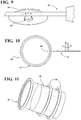
- the method may further include the step of installing the rings on a mandrel 58 to size the final gap 50 to a predetermined dimension during the heat treating step. This is shown in Figure 11 .
- the method step of machining the stock bar to the initial outer diameter may include turning the stock bar relative to a machining tool.
- the step of finishing the initial outer diameter to a predetermined profile may include turning the stock bar 26 relative to a profiling tool 62 ( Figure 5 ).
- the step of machining the stock bar 26 to the L-shaped cross section may include turning the stock bar 26 relative to a machining tool 60
- the step of detaching the piston ring 20 from the stock bar 26 may include turning the stock bar 26 relative to a parting tool 64 ( Figure 8 ).
- turning is a specific machining process wherein the piston ring is rotated relative to the tool using a lathe. It should be appreciated that the machining, finishing, and parting steps provided are not limited to turning and can be accomplished using a variety of other tools and operations.
- the stock bar 26 can be made of a fine grained spheroidal cast iron. However, it is envisioned that other materials may be used.
- a method for manufacturing a low tension piston ring having a finished outer diameter is also provided (but not claimed).
- the method includes the steps of machining a stock bar to an initial outer diameter slightly greater than the finished outer diameter of the piston ring, finishing the initial outer diameter of the stock bar to a predetermined profile having a nominal diameter equal to the finished outer diameter, and machining the stock bar to a predetermined cross-section.
- the method continues with the step of detaching the piston ring from the stock bar in response to completing all tension-inducing operations.
- These operations include machining the stock bar to an initial outer diameter, finishing the stock bar to a predetermined profile, and machining the stock bar to a predetermined cross-section.
- the step of machining a stock bar to an initial outer diameter slightly greater than the finished outer diameter of the piston ring may include finishing the initial outer diameter of the stock bar to a predetermined profile having a rounded shape.
- the step of machining the stock bar to a predetermined cross-section may include machining the stock bar to a keystone shaped cross-section or a semi-keystone shaped cross-section.
- the dykes-type piston ring 20 that is produced includes an annular ring body 68 presenting a generally L-shaped cross-section 34 .
- the L-shaped cross-section 34 is comprised of and defined by a lip section 36 extending longitudinally relative to the ring body 68 and a tail section 38 having a pair of sides 40 extending radially inwardly from the lip section 36 .
- the annular ring body 68 also presents a pair of lateral faces 70 defining a final gap 50 therebetween. It should be appreciated that the final gap 50 is created by the method step of cutting the detached piston ring 20 longitudinally or discussed above.
- the pair of lateral faces 70 is arranged such that they face one another in an opposing spaced relationship.
- the annular ring body 68 has little or no tangential tension, ranging from zero to 25 Newtons (N), in a free and uncompressed state. This range is considerably less than the tangential tension residing in piston rings 20 produced by prior art methods. This low tangential tension also allows the piston ring 20 to have a miniscule final gap 50 in comparison to conventional piston rings including prior art dykes-type piston rings.
- the final gap 50 has a gap width 72 measurable between the lateral faces 70 ranging from zero to 0.4 millimeters when the annular ring body 68 is in its free and uncompressed state.
- the gap width 72 may range from zero to 0.1 millimeters when the annular ring body 68 is in its free and uncompressed state. These ranges are approximately thirty times smaller than the final gap of conventional piston rings.
- the dykes-type piston ring 20 of the subject invention may further include a tail section 38 having various shapes.
- the side of the tail section 38 may each tapper inwardly to define a keystone shaped cross-section.
- one of the sides of the tail section may tapper inwardly to define a semi-keystone shaped cross-section.
- the dykes-type piston ring 20 of the subject invention may further include an outer circumferential surface having a predetermined profile of arcuate shape.
- the arcuate, or rounded, shape of the predetermined profile may follow a symmetrical or asymmetrical curve.
- the predetermined profile may follow an asymmetrical curve as shown in Figures 5 and 6 where the curve is defined by a pair of arcs 42 converging at a tangent point 44 .
- the arcs 42 can have different radii 46 .
- the predetermined profile 30 may have a flat linear shape arranged along the longitudinal direction or sloped at an angle relative to the longitudinal direction.
Landscapes
- Engineering & Computer Science (AREA)
- General Engineering & Computer Science (AREA)
- Mechanical Engineering (AREA)
- Pistons, Piston Rings, And Cylinders (AREA)
Claims (11)
- Verfahren zur Herstellung eines Niederspannungs-Dykes-Kolbenrings (20), der einen fertigen Außendurchmesser aufweist, umfassend die Schritte:Bearbeiten eines Stabs (26) zu einem anfänglichen Außendurchmesser;Fertigstellen des anfänglichen Außendurchmessers des Stabs (26) zu einem vorbestimmten Profil (30), das einen Nenndurchmesser (32) aufweist, der zwischen 0,4 mm und 3 mm kleiner als der anfängliche Außendurchmesser ist;Bearbeiten des Stabs (26) zu einem allgemein L-förmigen Querschnitt, um einen Dykes-Kolbenring (20) gemäß den verbleibenden Abschnitten des Stabs (26) zu produzieren, undLösen des Kolbenrings (20) von dem Stab (26) erst, nachdem die Schritte des Bearbeitens des Stabs (26) zu dem anfänglichen Außendurchmesser und des Fertigstellens des Stabs (26) zu einem vorbestimmten Profil und des Bearbeitens des Stabs zu einem L-förmigen Querschnitt abgeschlossen sind.
- Verfahren nach Anspruch 1, wobei das vorbestimmte Profil eine abgerundete Form aufweist, die vorzugsweise durch ein Paar von Bögen (42) definiert ist, die an einem tangentialen Punkt zusammenlaufen.
- Verfahren nach Anspruch 1 oder 2, wobei der L-förmige Querschnitt einen Lippenabschnitt (36), der sich längs erstreckt, und einen hinteren Abschnitt (38), der sich radial einwärts von dem Lippenabschnitt (36) erstreckt, einschließt.
- Verfahren nach Anspruch 3, wobei der hintere Abschnitt (38) zu einem keilförmigen Querschnitt bearbeitet wird.
- Verfahren nach Anspruch 3, wobei der hintere Abschnitt (38) zu einem halbkeilförmigen Querschnitt bearbeitet wird.
- Verfahren nach einem der vorstehenden Ansprüche, wobei der Schritt des Bearbeitens des Stabs (26) zu dem anfänglichen Außendurchmesser das Drehen des Stabs (26) in Bezug auf ein Bearbeitungswerkzeug (60) einschließt.
- Verfahren nach einem der Ansprüche 1 bis 5, wobei der Schritt des Fertigstellens des anfänglichen Außendurchmessers zu einem vorbestimmten Profil das Drehen des Stabs (26) in Bezug auf ein Profilwerkzeug (62) einschließt.
- Verfahren nach einem der Ansprüche 1 bis 7, wobei der Schritt des Bearbeitens des Stabs zu dem L-förmigen Querschnitt das Drehen des Stabs (26) in Bezug auf ein Bearbeitungswerkzeug (60) einschließt.
- Verfahren nach einem der vorstehenden Ansprüche, wobei der Schritt des Lösens des Kolbenrings von dem Stab das Drehen des Stabs (26) in Bezug auf ein Trennwerkzeug (64) einschließt.
- Verfahren nach einem der vorstehenden Ansprüche, weiter umfassend den Schritt des Läppens des Kolbenrings (20) zu einer abschließenden Längsdicke.
- Verfahren nach einem der vorstehenden Ansprüche, weiter umfassend den Schritt des Längsschneidens des Kolbenrings (20) zum Bilden eines abschließenden Spalts (50).
Applications Claiming Priority (2)
| Application Number | Priority Date | Filing Date | Title |
|---|---|---|---|
| US13/827,255 US9261190B2 (en) | 2013-03-14 | 2013-03-14 | Low tension piston rings and method for manufacturing the same |
| PCT/US2014/019714 WO2014158734A1 (en) | 2013-03-14 | 2014-03-01 | Dykes-type piston rings and method for manufacturing the same |
Publications (3)
| Publication Number | Publication Date |
|---|---|
| EP2969384A1 EP2969384A1 (de) | 2016-01-20 |
| EP2969384B1 true EP2969384B1 (de) | 2018-04-25 |
| EP2969384B8 EP2969384B8 (de) | 2018-07-04 |
Family
ID=50336538
Family Applications (1)
| Application Number | Title | Priority Date | Filing Date |
|---|---|---|---|
| EP14711380.7A Not-in-force EP2969384B8 (de) | 2013-03-14 | 2014-03-01 | Dykes-kolbenringe und verfahren zur herstellung davon |
Country Status (7)
| Country | Link |
|---|---|
| US (2) | US9261190B2 (de) |
| EP (1) | EP2969384B8 (de) |
| JP (2) | JP6527501B2 (de) |
| KR (1) | KR20150129831A (de) |
| CN (2) | CN105163899B (de) |
| BR (1) | BR112015022712A2 (de) |
| WO (1) | WO2014158734A1 (de) |
Families Citing this family (6)
| Publication number | Priority date | Publication date | Assignee | Title |
|---|---|---|---|---|
| GB2590780B (en) * | 2018-06-19 | 2022-12-07 | Halliburton Energy Services Inc | Metallic ring for sealing a downhole rotary steering piston |
| DE102018122258B3 (de) * | 2018-09-12 | 2019-12-24 | Federal-Mogul Burscheid Gmbh | Kolbenring und kolben mit innenliegender nutversiegelung |
| CN110170805A (zh) * | 2019-06-13 | 2019-08-27 | 哈尔滨汽轮机厂有限责任公司 | 一种活塞环的加工方法 |
| TW202413407A (zh) | 2022-08-15 | 2024-04-01 | 國立大學法人東京大學 | 使用絲狀真菌之免疫球蛋白或多聚體免疫球蛋白之製造方法 |
| KR20250158030A (ko) | 2023-03-03 | 2025-11-05 | 고쿠리츠다이가쿠호우진 도쿄다이가쿠 | 면역 글로불린 |
| EP4682408A1 (de) | 2024-07-18 | 2026-01-21 | WinGD Ltd. | Kolbenring |
Family Cites Families (34)
| Publication number | Priority date | Publication date | Assignee | Title |
|---|---|---|---|---|
| US1186980A (en) | 1913-10-29 | 1916-06-13 | Lyman E Warren | Method for making a piston packing-ring. |
| US1329271A (en) | 1919-03-08 | 1920-01-27 | S D Hartog Mfg Company | Method of manufacturing piston-rings |
| US1654736A (en) | 1924-10-27 | 1928-01-03 | Herman H Kistner | Piston ring and method of making same |
| US1561336A (en) | 1924-11-25 | 1925-11-10 | John F Mcglenn | Method of producing piston rings |
| US1691120A (en) | 1927-12-30 | 1928-11-13 | American Hammered Piston Ring | Method of grinding piston rings |
| US1913136A (en) | 1928-08-06 | 1933-06-06 | Wilkening Mfg Co | Quick-seating piston ring and method of making the same |
| US1996603A (en) | 1929-12-18 | 1935-04-02 | Wilkening Mfg Co | Method of making piston rings |
| US1951397A (en) | 1932-07-29 | 1934-03-20 | Renu Parts Corp | Manufacture of piston rings |
| GB415325A (en) | 1934-01-19 | 1934-08-23 | Wellworthy Ltd | A step in the manufacture of piston-rings |
| US2093263A (en) | 1935-09-03 | 1937-09-14 | George Kessler | Method of forming piston rings |
| US2281426A (en) | 1938-04-23 | 1942-04-28 | Budd Wheel Co | Piston ring and method of making same |
| US3834719A (en) * | 1970-10-27 | 1974-09-10 | Nippon Piston Ring Co Ltd | Piston head assembly having an l-shaped piston ring |
| GB1454747A (en) | 1975-01-16 | 1976-11-03 | United Stirling Ab & Co | Sealing device to oppose leakage of fluid between two surfaces subject to relative movement |
| JPS6032359Y2 (ja) * | 1979-01-23 | 1985-09-27 | 川崎重工業株式会社 | 2サイクル内燃機関のガスシ−ル機構 |
| JPS6315561Y2 (de) * | 1980-09-04 | 1988-05-02 | ||
| JPS5919773A (ja) * | 1982-07-27 | 1984-02-01 | Teikoku Piston Ring Co Ltd | L字形断面の鋼製ピストンリングの製造方法 |
| JPS5942363U (ja) * | 1982-09-14 | 1984-03-19 | 帝国ピストンリング株式会社 | 鋼製オイルリング |
| JPS59163151U (ja) * | 1983-04-18 | 1984-11-01 | 三菱重工業株式会社 | ピストンリング |
| JPH01188625A (ja) * | 1988-01-22 | 1989-07-27 | Tokushu Hatsujo Kogyo Kk | 鋼製ピストンリングの製造方法 |
| JP2580229B2 (ja) * | 1988-02-19 | 1997-02-12 | イズミ工業株式会社 | 内燃機関用ピストン |
| GB9000446D0 (en) * | 1990-01-09 | 1990-03-07 | Ae Piston Products | Piston rings |
| GB2239926B (en) | 1990-01-09 | 1994-03-02 | Ae Piston Products | Piston rings |
| US5251915A (en) * | 1990-02-12 | 1993-10-12 | General Motors Corporation | Piston and ring assembly |
| JPH07197107A (ja) * | 1993-12-29 | 1995-08-01 | Honda Motor Co Ltd | TiAl系金属間化合物製リング部材の製造方法 |
| JPH08238552A (ja) * | 1995-03-03 | 1996-09-17 | Honda Motor Co Ltd | 非真円形横断面を有する筒状鋳物の横型遠心鋳造法 |
| GB2304173B (en) * | 1995-08-08 | 1997-09-10 | Martin James Quinney | Manufacturing piston rings |
| JP2000009225A (ja) * | 1998-06-24 | 2000-01-11 | Riken Corp | ピストンリング |
| DE50104690D1 (de) | 2001-07-09 | 2005-01-05 | Burckhardt Compression Ag Wint | Kolbenring |
| JP4008278B2 (ja) * | 2002-04-03 | 2007-11-14 | 帝国ピストンリング株式会社 | 組合せピストンリング |
| CN1796042A (zh) * | 2004-12-21 | 2006-07-05 | 仪征市蓝星机械有限公司 | 球墨铸铁活塞环氮化工艺 |
| JP2007224939A (ja) * | 2006-02-21 | 2007-09-06 | Daihatsu Motor Co Ltd | 二サイクル内燃機関用ピストンリング |
| CN101387239A (zh) * | 2007-09-11 | 2009-03-18 | 韦加伟 | 楔形状搭口活塞环加工工艺 |
| US20090174150A1 (en) * | 2008-01-08 | 2009-07-09 | Thomas Smith | Lateral side protection of a piston ring with a thermally sprayed coating |
| IT1403414B1 (it) | 2010-12-21 | 2013-10-17 | Sarl Maritime Trading Company | Metodo per la fabbricazione di anelli di tenuta per pistoni di motori endotermici |
-
2013
- 2013-03-14 US US13/827,255 patent/US9261190B2/en active Active
-
2014
- 2014-03-01 WO PCT/US2014/019714 patent/WO2014158734A1/en not_active Ceased
- 2014-03-01 CN CN201480025052.2A patent/CN105163899B/zh not_active Expired - Fee Related
- 2014-03-01 EP EP14711380.7A patent/EP2969384B8/de not_active Not-in-force
- 2014-03-01 JP JP2016500528A patent/JP6527501B2/ja not_active Expired - Fee Related
- 2014-03-01 KR KR1020157028921A patent/KR20150129831A/ko not_active Ceased
- 2014-03-01 CN CN201810488841.XA patent/CN108561240A/zh active Pending
- 2014-03-01 BR BR112015022712A patent/BR112015022712A2/pt not_active Application Discontinuation
-
2016
- 2016-01-21 US US15/002,753 patent/US9494233B2/en active Active
-
2018
- 2018-12-05 JP JP2018228285A patent/JP2019070441A/ja active Pending
Non-Patent Citations (1)
| Title |
|---|
| None * |
Also Published As
| Publication number | Publication date |
|---|---|
| BR112015022712A2 (pt) | 2017-07-18 |
| US20160138714A1 (en) | 2016-05-19 |
| CN105163899A (zh) | 2015-12-16 |
| KR20150129831A (ko) | 2015-11-20 |
| JP6527501B2 (ja) | 2019-06-05 |
| JP2019070441A (ja) | 2019-05-09 |
| US9261190B2 (en) | 2016-02-16 |
| CN108561240A (zh) | 2018-09-21 |
| JP2016512309A (ja) | 2016-04-25 |
| EP2969384A1 (de) | 2016-01-20 |
| US9494233B2 (en) | 2016-11-15 |
| CN105163899B (zh) | 2018-06-29 |
| WO2014158734A1 (en) | 2014-10-02 |
| US20140265148A1 (en) | 2014-09-18 |
| EP2969384B8 (de) | 2018-07-04 |
Similar Documents
| Publication | Publication Date | Title |
|---|---|---|
| US9494233B2 (en) | Low tension piston rings and method for manufacturing the same | |
| US8402650B2 (en) | Built-up camshaft | |
| US6470775B1 (en) | Crankshaft machining + hardening + machining + finishing | |
| JP5180991B2 (ja) | シリンダ・ブロックおよびシリンダ・ブロックを製造するための方法 | |
| US20140325840A1 (en) | Method of manufacturing cylinder line for engine | |
| US6742252B1 (en) | Crankshaft machining and finishing | |
| US3021593A (en) | Method of making metal rings | |
| EP2769781B1 (de) | Kaltwalzverfahren zur Herstellung von Lagerringen | |
| US9719596B2 (en) | Piston ring for internal combustion engines with increased fatigue strength, and method for producing same | |
| US6883358B2 (en) | Method of producing sliding sleeves for gearshift mechanisms | |
| JP2016512309A5 (de) | ||
| CN103752919B (zh) | 一种非圆胀圈型密封环加工方法 | |
| US10371178B2 (en) | Hydraulic actuator device | |
| JP5863270B2 (ja) | リング状素形材の製造方法 | |
| JP5439248B2 (ja) | 渦巻形ガスケット加工装置 | |
| JP5291440B2 (ja) | 鋼製2ピース組合せオイルリング本体の製造方法及びそれを用いた鋼製2ピース組合せオイルリング | |
| CN101967646A (zh) | 提高柴油机组合活塞钢顶环槽耐磨性的方法 | |
| CN104118271B (zh) | 一种花键轮毂及其加工方法 | |
| US1954714A (en) | Method of making piston rings | |
| US11680540B2 (en) | Piston for an internal combustion engine and production method | |
| US1856240A (en) | Process of making piston rings | |
| RU2053093C1 (ru) | Способ изготовления поршневых колец | |
| CN100475383C (zh) | 生产旋转对称的下切轮廓的方法 | |
| JPH0359302B2 (de) | ||
| JPS62279043A (ja) | 鋼製ピストンリングの製造方法 |
Legal Events
| Date | Code | Title | Description |
|---|---|---|---|
| PUAI | Public reference made under article 153(3) epc to a published international application that has entered the european phase |
Free format text: ORIGINAL CODE: 0009012 |
|
| 17P | Request for examination filed |
Effective date: 20151012 |
|
| AK | Designated contracting states |
Kind code of ref document: A1 Designated state(s): AL AT BE BG CH CY CZ DE DK EE ES FI FR GB GR HR HU IE IS IT LI LT LU LV MC MK MT NL NO PL PT RO RS SE SI SK SM TR |
|
| AX | Request for extension of the european patent |
Extension state: BA ME |
|
| DAX | Request for extension of the european patent (deleted) | ||
| STAA | Information on the status of an ep patent application or granted ep patent |
Free format text: STATUS: EXAMINATION IS IN PROGRESS |
|
| 17Q | First examination report despatched |
Effective date: 20161125 |
|
| REG | Reference to a national code |
Ref country code: DE Ref legal event code: R079 Ref document number: 602014024394 Country of ref document: DE Free format text: PREVIOUS MAIN CLASS: B23P0015060000 Ipc: F16J0009140000 |
|
| GRAP | Despatch of communication of intention to grant a patent |
Free format text: ORIGINAL CODE: EPIDOSNIGR1 |
|
| STAA | Information on the status of an ep patent application or granted ep patent |
Free format text: STATUS: GRANT OF PATENT IS INTENDED |
|
| RIC1 | Information provided on ipc code assigned before grant |
Ipc: F16J 9/02 20060101ALI20180119BHEP Ipc: B23P 15/06 20060101ALI20180119BHEP Ipc: F16J 9/14 20060101AFI20180119BHEP |
|
| INTG | Intention to grant announced |
Effective date: 20180222 |
|
| GRAA | (expected) grant |
Free format text: ORIGINAL CODE: 0009210 |
|
| GRAS | Grant fee paid |
Free format text: ORIGINAL CODE: EPIDOSNIGR3 |
|
| STAA | Information on the status of an ep patent application or granted ep patent |
Free format text: STATUS: THE PATENT HAS BEEN GRANTED |
|
| AK | Designated contracting states |
Kind code of ref document: B1 Designated state(s): AL AT BE BG CH CY CZ DE DK EE ES FI FR GB GR HR HU IE IS IT LI LT LU LV MC MK MT NL NO PL PT RO RS SE SI SK SM TR |
|
| REG | Reference to a national code |
Ref country code: GB Ref legal event code: FG4D |
|
| REG | Reference to a national code |
Ref country code: CH Ref legal event code: EP |
|
| REG | Reference to a national code |
Ref country code: AT Ref legal event code: REF Ref document number: 993267 Country of ref document: AT Kind code of ref document: T Effective date: 20180515 |
|
| REG | Reference to a national code |
Ref country code: IE Ref legal event code: FG4D |
|
| REG | Reference to a national code |
Ref country code: DE Ref legal event code: R096 Ref document number: 602014024394 Country of ref document: DE |
|
| RAP2 | Party data changed (patent owner data changed or rights of a patent transferred) |
Owner name: FEDERAL-MOGUL LLC |
|
| REG | Reference to a national code |
Ref country code: DE Ref legal event code: R082 Ref document number: 602014024394 Country of ref document: DE Representative=s name: HOFFMANN - EITLE PATENT- UND RECHTSANWAELTE PA, DE Ref country code: DE Ref legal event code: R081 Ref document number: 602014024394 Country of ref document: DE Owner name: FEDERAL-MOGUL LLC, SOUTHFIELD, US Free format text: FORMER OWNER: FEDERAL-MOGUL CORPORATION, SOUTHFIELD, MICH., US |
|
| REG | Reference to a national code |
Ref country code: NL Ref legal event code: MP Effective date: 20180425 |
|
| REG | Reference to a national code |
Ref country code: LT Ref legal event code: MG4D |
|
| PG25 | Lapsed in a contracting state [announced via postgrant information from national office to epo] |
Ref country code: NL Free format text: LAPSE BECAUSE OF FAILURE TO SUBMIT A TRANSLATION OF THE DESCRIPTION OR TO PAY THE FEE WITHIN THE PRESCRIBED TIME-LIMIT Effective date: 20180425 |
|
| PG25 | Lapsed in a contracting state [announced via postgrant information from national office to epo] |
Ref country code: FI Free format text: LAPSE BECAUSE OF FAILURE TO SUBMIT A TRANSLATION OF THE DESCRIPTION OR TO PAY THE FEE WITHIN THE PRESCRIBED TIME-LIMIT Effective date: 20180425 Ref country code: NO Free format text: LAPSE BECAUSE OF FAILURE TO SUBMIT A TRANSLATION OF THE DESCRIPTION OR TO PAY THE FEE WITHIN THE PRESCRIBED TIME-LIMIT Effective date: 20180725 Ref country code: BG Free format text: LAPSE BECAUSE OF FAILURE TO SUBMIT A TRANSLATION OF THE DESCRIPTION OR TO PAY THE FEE WITHIN THE PRESCRIBED TIME-LIMIT Effective date: 20180725 Ref country code: ES Free format text: LAPSE BECAUSE OF FAILURE TO SUBMIT A TRANSLATION OF THE DESCRIPTION OR TO PAY THE FEE WITHIN THE PRESCRIBED TIME-LIMIT Effective date: 20180425 Ref country code: SE Free format text: LAPSE BECAUSE OF FAILURE TO SUBMIT A TRANSLATION OF THE DESCRIPTION OR TO PAY THE FEE WITHIN THE PRESCRIBED TIME-LIMIT Effective date: 20180425 Ref country code: LT Free format text: LAPSE BECAUSE OF FAILURE TO SUBMIT A TRANSLATION OF THE DESCRIPTION OR TO PAY THE FEE WITHIN THE PRESCRIBED TIME-LIMIT Effective date: 20180425 Ref country code: PL Free format text: LAPSE BECAUSE OF FAILURE TO SUBMIT A TRANSLATION OF THE DESCRIPTION OR TO PAY THE FEE WITHIN THE PRESCRIBED TIME-LIMIT Effective date: 20180425 |
|
| PG25 | Lapsed in a contracting state [announced via postgrant information from national office to epo] |
Ref country code: LV Free format text: LAPSE BECAUSE OF FAILURE TO SUBMIT A TRANSLATION OF THE DESCRIPTION OR TO PAY THE FEE WITHIN THE PRESCRIBED TIME-LIMIT Effective date: 20180425 Ref country code: GR Free format text: LAPSE BECAUSE OF FAILURE TO SUBMIT A TRANSLATION OF THE DESCRIPTION OR TO PAY THE FEE WITHIN THE PRESCRIBED TIME-LIMIT Effective date: 20180726 Ref country code: HR Free format text: LAPSE BECAUSE OF FAILURE TO SUBMIT A TRANSLATION OF THE DESCRIPTION OR TO PAY THE FEE WITHIN THE PRESCRIBED TIME-LIMIT Effective date: 20180425 Ref country code: RS Free format text: LAPSE BECAUSE OF FAILURE TO SUBMIT A TRANSLATION OF THE DESCRIPTION OR TO PAY THE FEE WITHIN THE PRESCRIBED TIME-LIMIT Effective date: 20180425 |
|
| REG | Reference to a national code |
Ref country code: AT Ref legal event code: MK05 Ref document number: 993267 Country of ref document: AT Kind code of ref document: T Effective date: 20180425 |
|
| PG25 | Lapsed in a contracting state [announced via postgrant information from national office to epo] |
Ref country code: PT Free format text: LAPSE BECAUSE OF FAILURE TO SUBMIT A TRANSLATION OF THE DESCRIPTION OR TO PAY THE FEE WITHIN THE PRESCRIBED TIME-LIMIT Effective date: 20180827 |
|
| REG | Reference to a national code |
Ref country code: DE Ref legal event code: R097 Ref document number: 602014024394 Country of ref document: DE |
|
| PG25 | Lapsed in a contracting state [announced via postgrant information from national office to epo] |
Ref country code: EE Free format text: LAPSE BECAUSE OF FAILURE TO SUBMIT A TRANSLATION OF THE DESCRIPTION OR TO PAY THE FEE WITHIN THE PRESCRIBED TIME-LIMIT Effective date: 20180425 Ref country code: DK Free format text: LAPSE BECAUSE OF FAILURE TO SUBMIT A TRANSLATION OF THE DESCRIPTION OR TO PAY THE FEE WITHIN THE PRESCRIBED TIME-LIMIT Effective date: 20180425 Ref country code: AT Free format text: LAPSE BECAUSE OF FAILURE TO SUBMIT A TRANSLATION OF THE DESCRIPTION OR TO PAY THE FEE WITHIN THE PRESCRIBED TIME-LIMIT Effective date: 20180425 Ref country code: RO Free format text: LAPSE BECAUSE OF FAILURE TO SUBMIT A TRANSLATION OF THE DESCRIPTION OR TO PAY THE FEE WITHIN THE PRESCRIBED TIME-LIMIT Effective date: 20180425 Ref country code: CZ Free format text: LAPSE BECAUSE OF FAILURE TO SUBMIT A TRANSLATION OF THE DESCRIPTION OR TO PAY THE FEE WITHIN THE PRESCRIBED TIME-LIMIT Effective date: 20180425 Ref country code: SK Free format text: LAPSE BECAUSE OF FAILURE TO SUBMIT A TRANSLATION OF THE DESCRIPTION OR TO PAY THE FEE WITHIN THE PRESCRIBED TIME-LIMIT Effective date: 20180425 |
|
| PG25 | Lapsed in a contracting state [announced via postgrant information from national office to epo] |
Ref country code: SM Free format text: LAPSE BECAUSE OF FAILURE TO SUBMIT A TRANSLATION OF THE DESCRIPTION OR TO PAY THE FEE WITHIN THE PRESCRIBED TIME-LIMIT Effective date: 20180425 |
|
| PLBE | No opposition filed within time limit |
Free format text: ORIGINAL CODE: 0009261 |
|
| STAA | Information on the status of an ep patent application or granted ep patent |
Free format text: STATUS: NO OPPOSITION FILED WITHIN TIME LIMIT |
|
| 26N | No opposition filed |
Effective date: 20190128 |
|
| PGFP | Annual fee paid to national office [announced via postgrant information from national office to epo] |
Ref country code: IT Payment date: 20190320 Year of fee payment: 6 |
|
| PG25 | Lapsed in a contracting state [announced via postgrant information from national office to epo] |
Ref country code: SI Free format text: LAPSE BECAUSE OF FAILURE TO SUBMIT A TRANSLATION OF THE DESCRIPTION OR TO PAY THE FEE WITHIN THE PRESCRIBED TIME-LIMIT Effective date: 20180425 |
|
| PGFP | Annual fee paid to national office [announced via postgrant information from national office to epo] |
Ref country code: FR Payment date: 20190220 Year of fee payment: 6 |
|
| PG25 | Lapsed in a contracting state [announced via postgrant information from national office to epo] |
Ref country code: MC Free format text: LAPSE BECAUSE OF FAILURE TO SUBMIT A TRANSLATION OF THE DESCRIPTION OR TO PAY THE FEE WITHIN THE PRESCRIBED TIME-LIMIT Effective date: 20180425 |
|
| REG | Reference to a national code |
Ref country code: CH Ref legal event code: PL |
|
| GBPC | Gb: european patent ceased through non-payment of renewal fee |
Effective date: 20190301 |
|
| PG25 | Lapsed in a contracting state [announced via postgrant information from national office to epo] |
Ref country code: AL Free format text: LAPSE BECAUSE OF FAILURE TO SUBMIT A TRANSLATION OF THE DESCRIPTION OR TO PAY THE FEE WITHIN THE PRESCRIBED TIME-LIMIT Effective date: 20180425 Ref country code: LU Free format text: LAPSE BECAUSE OF NON-PAYMENT OF DUE FEES Effective date: 20190301 |
|
| REG | Reference to a national code |
Ref country code: BE Ref legal event code: MM Effective date: 20190331 |
|
| PG25 | Lapsed in a contracting state [announced via postgrant information from national office to epo] |
Ref country code: IE Free format text: LAPSE BECAUSE OF NON-PAYMENT OF DUE FEES Effective date: 20190301 Ref country code: GB Free format text: LAPSE BECAUSE OF NON-PAYMENT OF DUE FEES Effective date: 20190301 Ref country code: LI Free format text: LAPSE BECAUSE OF NON-PAYMENT OF DUE FEES Effective date: 20190331 Ref country code: CH Free format text: LAPSE BECAUSE OF NON-PAYMENT OF DUE FEES Effective date: 20190331 |
|
| PG25 | Lapsed in a contracting state [announced via postgrant information from national office to epo] |
Ref country code: BE Free format text: LAPSE BECAUSE OF NON-PAYMENT OF DUE FEES Effective date: 20190331 |
|
| PG25 | Lapsed in a contracting state [announced via postgrant information from national office to epo] |
Ref country code: TR Free format text: LAPSE BECAUSE OF FAILURE TO SUBMIT A TRANSLATION OF THE DESCRIPTION OR TO PAY THE FEE WITHIN THE PRESCRIBED TIME-LIMIT Effective date: 20180425 |
|
| PGFP | Annual fee paid to national office [announced via postgrant information from national office to epo] |
Ref country code: DE Payment date: 20200214 Year of fee payment: 7 |
|
| PG25 | Lapsed in a contracting state [announced via postgrant information from national office to epo] |
Ref country code: MT Free format text: LAPSE BECAUSE OF NON-PAYMENT OF DUE FEES Effective date: 20190301 |
|
| PG25 | Lapsed in a contracting state [announced via postgrant information from national office to epo] |
Ref country code: FR Free format text: LAPSE BECAUSE OF NON-PAYMENT OF DUE FEES Effective date: 20200331 |
|
| PG25 | Lapsed in a contracting state [announced via postgrant information from national office to epo] |
Ref country code: CY Free format text: LAPSE BECAUSE OF FAILURE TO SUBMIT A TRANSLATION OF THE DESCRIPTION OR TO PAY THE FEE WITHIN THE PRESCRIBED TIME-LIMIT Effective date: 20180425 |
|
| PG25 | Lapsed in a contracting state [announced via postgrant information from national office to epo] |
Ref country code: IS Free format text: LAPSE BECAUSE OF FAILURE TO SUBMIT A TRANSLATION OF THE DESCRIPTION OR TO PAY THE FEE WITHIN THE PRESCRIBED TIME-LIMIT Effective date: 20180825 |
|
| PG25 | Lapsed in a contracting state [announced via postgrant information from national office to epo] |
Ref country code: HU Free format text: LAPSE BECAUSE OF FAILURE TO SUBMIT A TRANSLATION OF THE DESCRIPTION OR TO PAY THE FEE WITHIN THE PRESCRIBED TIME-LIMIT; INVALID AB INITIO Effective date: 20140301 |
|
| REG | Reference to a national code |
Ref country code: DE Ref legal event code: R119 Ref document number: 602014024394 Country of ref document: DE |
|
| PG25 | Lapsed in a contracting state [announced via postgrant information from national office to epo] |
Ref country code: IT Free format text: LAPSE BECAUSE OF NON-PAYMENT OF DUE FEES Effective date: 20200301 |
|
| PG25 | Lapsed in a contracting state [announced via postgrant information from national office to epo] |
Ref country code: DE Free format text: LAPSE BECAUSE OF NON-PAYMENT OF DUE FEES Effective date: 20211001 |
|
| PG25 | Lapsed in a contracting state [announced via postgrant information from national office to epo] |
Ref country code: MK Free format text: LAPSE BECAUSE OF FAILURE TO SUBMIT A TRANSLATION OF THE DESCRIPTION OR TO PAY THE FEE WITHIN THE PRESCRIBED TIME-LIMIT Effective date: 20180425 |