EP2969725B1 - Fahrradspannvorrichtung - Google Patents
Fahrradspannvorrichtung Download PDFInfo
- Publication number
- EP2969725B1 EP2969725B1 EP14719961.6A EP14719961A EP2969725B1 EP 2969725 B1 EP2969725 B1 EP 2969725B1 EP 14719961 A EP14719961 A EP 14719961A EP 2969725 B1 EP2969725 B1 EP 2969725B1
- Authority
- EP
- European Patent Office
- Prior art keywords
- shaft
- assembly
- skewer
- teeth
- lever
- Prior art date
- Legal status (The legal status is an assumption and is not a legal conclusion. Google has not performed a legal analysis and makes no representation as to the accuracy of the status listed.)
- Not-in-force
Links
Images


Classifications
-
- B—PERFORMING OPERATIONS; TRANSPORTING
- B62—LAND VEHICLES FOR TRAVELLING OTHERWISE THAN ON RAILS
- B62K—CYCLES; CYCLE FRAMES; CYCLE STEERING DEVICES; RIDER-OPERATED TERMINAL CONTROLS SPECIALLY ADAPTED FOR CYCLES; CYCLE AXLE SUSPENSIONS; CYCLE SIDECARS, FORECARS, OR THE LIKE
- B62K19/00—Cycle frames
- B62K19/30—Frame parts shaped to receive other cycle parts or accessories
- B62K19/38—Frame parts shaped to receive other cycle parts or accessories for attaching brake members
-
- B—PERFORMING OPERATIONS; TRANSPORTING
- B62—LAND VEHICLES FOR TRAVELLING OTHERWISE THAN ON RAILS
- B62K—CYCLES; CYCLE FRAMES; CYCLE STEERING DEVICES; RIDER-OPERATED TERMINAL CONTROLS SPECIALLY ADAPTED FOR CYCLES; CYCLE AXLE SUSPENSIONS; CYCLE SIDECARS, FORECARS, OR THE LIKE
- B62K25/00—Axle suspensions
- B62K25/02—Axle suspensions for mounting axles rigidly on cycle frame or fork, e.g. adjustably
-
- B—PERFORMING OPERATIONS; TRANSPORTING
- B60—VEHICLES IN GENERAL
- B60B—VEHICLE WHEELS; CASTORS; AXLES FOR WHEELS OR CASTORS; INCREASING WHEEL ADHESION
- B60B27/00—Hubs
- B60B27/02—Hubs adapted to be rotatably arranged on axle
- B60B27/023—Hubs adapted to be rotatably arranged on axle specially adapted for bicycles
- B60B27/026—Hubs adapted to be rotatably arranged on axle specially adapted for bicycles comprising quick release devices
-
- B—PERFORMING OPERATIONS; TRANSPORTING
- B62—LAND VEHICLES FOR TRAVELLING OTHERWISE THAN ON RAILS
- B62K—CYCLES; CYCLE FRAMES; CYCLE STEERING DEVICES; RIDER-OPERATED TERMINAL CONTROLS SPECIALLY ADAPTED FOR CYCLES; CYCLE AXLE SUSPENSIONS; CYCLE SIDECARS, FORECARS, OR THE LIKE
- B62K25/00—Axle suspensions
- B62K25/02—Axle suspensions for mounting axles rigidly on cycle frame or fork, e.g. adjustably
- B62K2025/025—Hinged axle clamps
-
- B—PERFORMING OPERATIONS; TRANSPORTING
- B62—LAND VEHICLES FOR TRAVELLING OTHERWISE THAN ON RAILS
- B62K—CYCLES; CYCLE FRAMES; CYCLE STEERING DEVICES; RIDER-OPERATED TERMINAL CONTROLS SPECIALLY ADAPTED FOR CYCLES; CYCLE AXLE SUSPENSIONS; CYCLE SIDECARS, FORECARS, OR THE LIKE
- B62K2206/00—Quick release mechanisms adapted for cycles
-
- F—MECHANICAL ENGINEERING; LIGHTING; HEATING; WEAPONS; BLASTING
- F16—ENGINEERING ELEMENTS AND UNITS; GENERAL MEASURES FOR PRODUCING AND MAINTAINING EFFECTIVE FUNCTIONING OF MACHINES OR INSTALLATIONS; THERMAL INSULATION IN GENERAL
- F16B—DEVICES FOR FASTENING OR SECURING CONSTRUCTIONAL ELEMENTS OR MACHINE PARTS TOGETHER, e.g. NAILS, BOLTS, CIRCLIPS, CLAMPS, CLIPS OR WEDGES; JOINTS OR JOINTING
- F16B37/00—Nuts or like thread-engaging members
- F16B37/08—Quickly-detachable or mountable nuts, e.g. consisting of two or more parts; Nuts movable along the bolt after tilting the nut
- F16B37/0807—Nuts engaged from the end of the bolt, e.g. axially slidable nuts
- F16B37/085—Nuts engaged from the end of the bolt, e.g. axially slidable nuts with at least one unthreaded portion in both the nut and the bolt
Definitions
- the present invention provides a fastener in accordance with independent claim 1 Preferred embodiments of the invention are reflected in the dependent claims.
- the invention herein may also be more broadly applicable to most types of vehicles, or to fasteners in general.
- the fastener according to the invention as defined by claim 1 includes a shaft and an engagement mechanism.
- the shaft has a longitudinal axis and an end with multiple teeth in series one after another partially along the longitudinal axis. Each tooth runs transverse to the longitudinal axis, the teeth being disposed on at least a first side of the shaft.
- the shaft includes an adjacent second side that is recessed relative to the first side, such that it does not extend as far from the longitudinal axis of the shaft.
- the engagement mechanism is configured to engage the multiple teeth on the shaft when the shaft is oriented in a first rotational position.
- the mechanism disengages the teeth on the shaft when the shaft is oriented in a second rotational position.
- the engagement mechanism includes teeth that selectively engage the shaft teeth in the first rotational position.
- a tensioning mechanism may be coupled to at least one of the shaft and the engagement mechanism.
- the tensioning mechanism operates to place tension on the shaft after the engagement mechanism is in the second rotational position with the teeth engaged.
- the tensioning mechanism includes a cam and a lever rotatable with the cam to move the cam and the engagement mechanism toward and away from the shaft.
- the tensioning mechanism further includes a secondary retention member to restrain the movement of the lever.
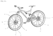
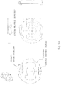
- Figures 1A and B illustrate a bicycle having disc brakes, dropouts, and QR levers front and rear.
- the bicycle includes a quick-release skewer (i.e., tension rod assemblies) assemblies 10, 10a, a front wheel 11, rear wheel 11a, a hub assemblies 16 (partially hidden behind the brake discs in Figure 1A ), and a fork assembly 20.
- the front portion of the bicycle further includes a bicycle left fork leg 12, a bicycle right fork leg 14, bicycle spokes 13, and brake discs 21.
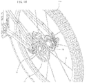
- the wheel hub assembly 16 includes left 17 and right 18 spoke flanges for attaching wheel spokes 13 ( Figure 1 ) to the wheel hub assembly 16.
- the wheel hub assembly 16 further includes a disc brake flange 19 for attaching a brake disc 21 ( Figure 1 ) to the disc brake flange 19.
- a skewer rod assembly 30 Located generally within the hub assembly 16 is a skewer rod assembly 30.
- a quick-release (QR) assembly 60 Located outboard of the left bicycle fork leg in Figure 2 is a quick-release (QR) assembly 60.
- a left end cap 26 with opposing flat spots abuts the left end portion of the hub assembly 16 and is mounted in the left fork leg slot 22.
- a right end cap 28 with opposing flat spots abuts the right end portion of the hub assembly 16 and is mounted in the right fork slot 14 as discussed above.
- Figure 2B is similar. Note that the slots in the fork legs accommodate longer axles 23 within inset recesses or slots 25. This form of the assembly can accommodate conversion of previous hub and axle assemblies to the improved arrangement with better handling of the braking forces.
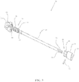
- FIG 3 illustrates an exploded isometric view of the skewer rod (i.e., tension rod) assembly 30 according to an embodiment of the present invention.
- the skewer assembly 30 includes a skewer rod 32.
- the skewer rod 32 is installed through a through-hole in the left 12 and right 14 fork legs and within a through-hole in an axle of the wheel hub 16 (See also Figure 2 ).
- the adjusting cylinder 34 illustrated has external threads on an inboard portion 36 of the adjusting cylinder 34.
- the adjusting cylinder 34 has external threads on an outboard portion 38 of the adjusting cylinder 34.
- the inboard portion 44 of the adjusting sleeve fits inside the through-hole ( Figure 2 ) in the right fork leg 14.
- the outboard portion 46 of the adjusting sleeve 40 has an outer surface configured as wide and narrow flats 48.
- the wide and narrow flats 48 forming a hexagonal outer surface on the adjusting sleeve 40 outboard portion 46 fit into mating wide and narrow flats 50 forming a hexagonal inner surface of the thumbnut 42. Accordingly, when the thumbnut 42 is rotated, the adjusting sleeve 40 is also rotated.
- a pin 52 secures the adjusting sleeve 40 to the skewer rod 32. Therefore, when the thumbnut 42 is rotated, the skewer rod 32 also rotates.
- the end of the skewer rod 32 opposite the thumbnut in Figure 3 has flats 54 on opposing sides of an outer surface of the end of the skewer rod 32.
- the same end of the skewer rod 32 in Figure 3 also has threaded circumferential portions 56 on opposing sides of an outer surface of the end of the skewer rod 32.
- Figure 3 also illustrates a protrusion 55 on an outer surface of the thumbnut.
- Figure 4 illustrates a detail view of a lower portion of the right fork leg 14 and a portion of the thumbnut 42 looking inward according to an embodiment.
- a protrusion 55 exists on an outer circumference of the thumbnut 42.
- the protrusion 55 is located within a circumferential recess 57 on an outboard side of a lower portion of the right fork leg.
- the protrusion 55 on the outer circumference of the thumbnut 42 acts in cooperation with the circumferential recess 57 on the right fork leg to prevent the thumbnut 42 from being rotated more than a quarter turn in a preferred embodiment. The reason for not allowing the thumbnut 42 to turn more than a quarter turn will be explained further in the description of Figure 5 below.
- Figure 5 illustrates an exploded isometric view of the quick-release assembly 60 according to an embodiment.
- the end of the skewer rod 32 in Figure 3 (with flats 54 and threaded circumferential portions 56 on opposing sides of an outer surface of the skewer rod 32) engages a partially threaded bore in a partially internally threaded block 62.
- the end of the skewer rod 32 in Figure 3 with flats 54 and threaded circumferential portions 56 is installed through a through-hole in the left fork bushing 61 into the partially threaded bore of the partially internally threaded block 62.
- the skewer rod 32 is oriented in the bore with the flats 54 of the skewer rod 32 aligned with the opposing threaded portions of the partially internally threaded block 62 such that it slides past the threaded bore portions without interference.
- a pin 64 inserted into the partially internally threaded block 62 and that protrudes into the bore, acts as a stop to allow the end of the skewer rod 32 to be inserted into a proper depth of partially threaded bore of the partially internally threaded block 62. This proper depth insertion of the skewer rod 32 assures that the quick-release skewer assembly 10 is properly clamped to the left 12 and right 14 fork legs.
- Rotating the thumbnut 42 (see also Figure 4 ) and attached skewer rod 32 causes the threaded circumferential portions 56 on the skewer rod 32 to threadably engage the opposing threaded portions of the partially internally threaded block 62.
- the partially internally threaded block 62 is matingly housed within a hole 65 in the housing 66.
- the partially internally threaded block 62 is free to move axially within the hole 65 of the partially internally threaded cylinder housing 66.
- the block 62 cannot rotate axially within the housing 66 as the square cross section of the block 62 mates with the internally square hole 65.
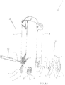
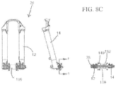
- Figure 6 illustrates an isometric view of a quick-release skewer assembly 100 looking toward a rear direction of a bicycle according to another embodiment.
- the quick-release skewer assembly 100 of Figures 6-8 is primarily intended for hub assemblies 116 with a 15 mm axle, but the embodiments of Figures 6-8 are not limited to this size axle.
- the description of the quick-release skewer assembly 100 of Figure 6 is the same, for the most part as Figure 2 , so parts that are the same as described in Figure 2 will not be described again.
- the main difference between the quick-release skewer assembly 10 of Figure 2 and the quick-release skewer assembly 100 of Figure 6 is that the quick-release skewer assembly 100 of Figure 6 does not utilize the left end cap 26 and right end cap 28 as illustrated in Figure 2 .
- the adjusting cylinder 34 illustrated has external threads on an inboard portion 36 of the adjusting cylinder 34.
- the adjusting cylinder 34 has external threads on an outboard portion 38 of the adjusting cylinder 34.
- the threads on the inboard portion 36 and outboard portion 38 may be either left-handed, or right-handed.
- the external threads on the inboard portion 36 of the adjusting cylinder 34 allows the adjusting cylinder 34 to be threaded into a threaded bore in the skewer rod 132.
- the external threads on the outboard portion 38 of the adjusting cylinder allows the adjusting cylinder 34 to be threaded into a threaded bore on a thumbnut 42.
- a hex through-hole 39 in the adjusting cylinder 34 allows an Allen wrench to be inserted into the hex hole 39 through a hole in an end of the thumbnut 42 to adjust the amount of thread engagement of the external threads on the inboard portion 36 of the adjusting cylinder 34 to the threaded bore in the skewer rod 132, thus adjusting the relative position of the rod 132 to the thumbnut 42.
- the adjusting cylinder 34 may be installed so that the inboard portion 36 and outboard portion 38 are reversed to the orientation shown in Figure 7 .
- An outboard portion 146 of the skewer rod 132 proximal the right fork leg 14 has an outer surface configured as wide and narrow flats 148.
- a threaded shaft 149 is threadably engaged into a threaded bore on the end of the skewer rod 132 in Figure 7 .
- the end of the threaded shaft 149 has flats 154 on opposing sides of an outer surface of the end of the threaded shaft 149.
- the end of the threaded shaft 149 in Figure 7 also has threaded circumferential portions 156 on opposing sides of its outer surface.
- Figure 8A illustrates an exploded isometric view of the quick-release assembly 160 according to an embodiment.
- the description of the quick-release assembly 160 is virtually identical to Figure 5 , so the parts of the quick-release assembly 60 of Figure 5 that are the same in Figure 8 will not be descried again.
- the only difference between the quick-release assembly 60 of Figure 5 and the quick-release assembly 160 of Figure 8 is that a threaded smaller shaft 149 threadably engages the partially internally threaded block 62, instead of the skewer shaft 32 directly threadably engaging the partially internally threaded block 62, as was taught by Figure 3 .
- the protrusion 55 on the thumbnut 42 which is located within the circumferential recess 77 on the right fork leg as taught by Figure 4 , also applies to the embodiment of Figures 6-8 .
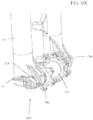
- Figure 8B shows the parts in a close-up cross-sectional view of the attachment of the tension rod (skewer rod 132) to the second embodiment of the QR assembly 160.
- the end of the threaded shaft 149 of the skewer rod 132 includes a non-threaded head 150. This head helps ensure that the skewer rod 132 is inserted all the way. The rod will not turn relative to the QR assembly 160 if the head does not extend past the complementary threads in the threaded cylinder 62. Thus, upon insertion, the end of the rod 132 abuts pin 64. At this point, head 150 clears the threads of the cylinder 62 such that the rod can be turned a partial turn (preferably a quarter turn) to engage the treads.
- Figure 10A illustrates the QR lever 78 in the closed position with a clamping force applied by the QR skewer assembly 200.
- Figure 10A also illustrates the outwardly biased protrusion 264 on the cam follower housing and the recesses 283 into which the protrusion drops to stop excessive rotation of the QR lever 78.
- a recess along the circumferential region of the desired turn of the lever may be used along with a tab or nub on the QR housing is used.
- a stop tab 284 is also used to positively locate the end of the lever turn.
- an Allen wrench may be inserted through a hole in an end of the thumbnut 42.
- the Allen wrench engages the hex through-hole 39 in the adjusting cylinder 34.
- the distance along a longitudinal axis of the adjusting cylinder 34 between the thumbnut 42, which clamps to the right fork leg 14 and the ppartially internally threaded cylinder housing 66, which clamps to the left fork leg 12 may be increased, to decrease the clamping force, or decreased, to increase the clamping force.
- FIG. 6-8 operates in a similar manner.
- One difference of the embodiment of Figures 6-8 with the embodiment of Figures 2-5 is that the embodiment of Figures 6-8 does not utilize an adjusting sleeve 40 ( Figure 3 ) in the skewer assembly 30. Instead, the function of the adjusting sleeve 40 of Figure 3 has been incorporated into the skewer rod 132 of Figure 7 in the embodiment of Figures 6-8 .
- the length of thread engagement of the partial circumferential threaded portions 237 on the skewer rod 232 and the partially threaded portions in the bore 241 of the right fork bushing 243 may be varied. By varying this length of thread engagement, the distance between the right fork bushing 243, which clamps to the right fork leg 14 and the cam follower housing 263, which clamps to the left fork leg 12 may be increased, to decrease the clamping force, or decreased, to increase the clamping force.
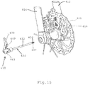
- Figure 11B illustrates the parts of fixed nut 342. It includes a cylinder 362 that engages the partially threaded end of the tension rod. A pin 364 stops the insertion of the tension rod to the right depth within the cylinder 362. Housing 366 covers the cylinder (which is actually rectangular in outer cross sectional shape to resist rotation within housing 366) and provides the correct shape to mate within the fork leg. Housing 366 includes a hole 368 to receive the set screw. An end screw cap 372 is secured to the end of the housing and also is fastened the outer end of cylinder 362. An inner cap 374 completes the assembly. It includes an inner aperture to receive the tension rod therethrough.
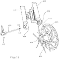
- the hub (with spokes, rim, and brake disc attached) may be removed from the fork legs as shown in Figure 16 .
- the nut on the distal side from the lever preferably remains secured to the left fork leg.
- Figure 17 shows the QR assembly inserted within the fork legs and hub in an intermediate position.
- the lever 478 is pivoted just 90 degrees outwardly from its tensioned and locked position.
- the lever is between the positions illustrated in Figures 12 and 13 .
- This is preferably an adjustment position for use of the adjustment nut 442.
- the lever 478 is opened 90 degrees - just parallel with the skewer rod - and the adjustment nut 442 is hand-tightened. This is a detent position when rotation of the lever must start building the clamping forces on the overall structure. Then the lever 478 may closed by pivoting it rearwardly into the riding position as shown in Figure 12 . Proper tension is ensured.
- Figure 18A is a top view of the QR assembly securing the wheel hub to the fork legs.
- This is a slightly different embodiment, as the adjuster nut has a different outer shape. Note that this shows the locked position of the QR lever. In the locked position, the camshaft 476 positions the cam at the outer placement for tensioning the skewer rod 432, as seen in Figure 18B.
- Figure 18B illustrates a cross-sectional view of the assembly shown in Figure 18A . Also shown in the cross-sectional view is the interface between the end caps 428 and the shoulders of the slots 422. This embodiment does not show the integration of the brake mount with the lower portion of the left fork leg. However, the force transfer is evident between the end caps and the shoulders of the fork slots or "dropout" slots.
- an axle sleeve 451 extends within the hub from near the outer sides of the end caps all the way through the hub. This also strengthens the hub to support the loads thereon.
- Figure 21 shows a side view of the structure from the disc-brake side.
- the adjustment nut 442 includes lobes for hand tightening. Tightening with a tool is thus discouraged.
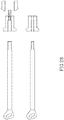
- the forces exerted on the dropout region of the fork legs are diagramed in Figure 23 .
- the tire contacts the ground and creates a lever arm upon braking that extends between the ground contact and the approximate middle of the brake pad contact with the brake disc or rotor.
- the lever arm opposing the continued rotation extends between the brake pad and the front axle.
- the force tends to pivot the wheel about the brake pad, thus causing a downward force on the hub mount. If the dropout opens downwardly, this force tends to pull off (or loosen) the wheel resulting in a potentially dangerous situation.
- the slots 422 of the present arrangement extend transverse to this wheel-dislocating force. Thus, the force is countered by the shoulders of the slots receiving the load from the end caps of the hub.
- QR lever 778 can be swung to a closed position to tighten the entire QR skewer assembly.
- cam 880 on the end of QR lever 878.
- a pin 881 extends from cam 880.
- Pin 881 is concentric with limit disk 845 to rotate within the aperture within housing 866, such that as QR lever rotates, cam 880 translates relative to housing 866 as discussed above.
Landscapes
- Engineering & Computer Science (AREA)
- Mechanical Engineering (AREA)
- Axle Suspensions And Sidecars For Cycles (AREA)
- Motorcycle And Bicycle Frame (AREA)
- Steering Devices For Bicycles And Motorcycles (AREA)
Claims (5)
- Befestigungselement (130), das aufweist:eine Welle (149) mit einer Längsachse, wobei die Welle teilweise entlang der Längsachse ein Ende mit mehreren Zähnen (156) hintereinander enthält, wobei jeder Zahn querliegend zu der Längsachse verläuft, wobei die Zähne wenigstens auf einer ersten Seite der Welle angeordnet sind, wobei die Welle eine benachbarte zweite Seite (154) aufweist, die relativ zu der ersten Seite in der Weise vertieft ist, dass diese nicht so weit von der Längsachse der Welle verläuft; undeinen Eingriffsmechanismus (62), der in der Weise konfiguriert ist, dass dieser mit den mehreren Zähnen an der Welle in Eingriff gelangt, wenn die Welle in einer ersten Drehstellung orientiert wird, und dass sich dieser von den Zähnen an der Welle löst, wenn die Welle in einer zweiten Drehstellung orientiert wird, wobeider Eingriffsmechanismus Zähne enthält, die in der ersten Drehstellung selektiv mit den Wellenzähnen in Eingriff sind,dadurch gekennzeichnet, dassdie Welle ferner an ihrem Ende jenseits der Zähne einen Kopf (150) enthält, wobei der Kopf von der Längsachse der Welle weiter als die zweite Seite verläuft, wobei der Kopf weiter als die zweite Seite in der Richtung der ersten Seite nach außen verläuft, sodass der Kopf mit den Zähnen des Eingriffsmechanismus nicht in Eingriff ist und somit die Drehung der Welle beschränkt, außer wenn der Kopf über die Zähne des Eingriffsmechanismus hinaus ausgefahren ist.
- Befestigungselement nach Anspruch 1, wobei die Welle einen zweiten Satz von Zähnen enthält, die entlang einer dritten Seite der Welle verlaufen, die den Zähnen der ersten Seite gegenüberliegen und zu der zweiten, vertieften Seite der Welle benachbart sind, wobei die Welle außerdem eine vierte Seite enthält, die relativ zu den Zähnen der dritten Seite und relativ zu den Zähnen der ersten Seite vertieft ist, wobei die zweite und die vierte Seite keine Zähne enthalten.
- Befestigungselement nach Anspruch 2, wobei der Eingriffsmechanismus zwei gegenüberliegende Sätze von Zähnen enthält, die nach Drehung der Welle in die zweite Drehstellung mit dem ersten und mit dem zweiten Satz von Wellenzähnen in Eingriff sind.
- Befestigungselement nach einem der vorhergehenden Ansprüche, das ferner einen Spannmechanismus (160) aufweist, der mit der Welle und/oder mit dem Eingriffsmechanismus gekoppelt ist, wobei der Spannmechanismus dafür betreibbar ist, die Welle unter Spannung zu setzen, nachdem der Eingriffsmechanismus in der zweiten Drehstellung mit den Zähnen in Eingriff ist.
- Befestigungselement nach Anspruch 4,
wobei der Spannmechanismus einen Nocken (80) und einen Hebel (78), der mit dem Nocken drehbar ist, um den Nocken und den Eingriffsmechanismus in Richtung der Welle und von dieser weg zu bewegen, enthält, und
wobei der Spannmechanismus ferner ein sekundäres Halteelement (88, 90) zum Beschränken der Bewegung des Hebels enthält.
Priority Applications (1)
| Application Number | Priority Date | Filing Date | Title |
|---|---|---|---|
| EP20211129.0A EP3805085A1 (de) | 2013-03-15 | 2014-03-13 | Fahrradspannvorrichtung |
Applications Claiming Priority (3)
| Application Number | Priority Date | Filing Date | Title |
|---|---|---|---|
| US13/839,168 US9409619B2 (en) | 2013-03-15 | 2013-03-15 | Bicycle tensioning device |
| US201361869015P | 2013-08-22 | 2013-08-22 | |
| PCT/US2014/026443 WO2014151783A2 (en) | 2013-03-15 | 2014-03-13 | Bicycle tensioning device |
Related Child Applications (1)
| Application Number | Title | Priority Date | Filing Date |
|---|---|---|---|
| EP20211129.0A Division EP3805085A1 (de) | 2013-03-15 | 2014-03-13 | Fahrradspannvorrichtung |
Publications (2)
| Publication Number | Publication Date |
|---|---|
| EP2969725A2 EP2969725A2 (de) | 2016-01-20 |
| EP2969725B1 true EP2969725B1 (de) | 2020-12-02 |
Family
ID=50588868
Family Applications (2)
| Application Number | Title | Priority Date | Filing Date |
|---|---|---|---|
| EP14719961.6A Not-in-force EP2969725B1 (de) | 2013-03-15 | 2014-03-13 | Fahrradspannvorrichtung |
| EP20211129.0A Withdrawn EP3805085A1 (de) | 2013-03-15 | 2014-03-13 | Fahrradspannvorrichtung |
Family Applications After (1)
| Application Number | Title | Priority Date | Filing Date |
|---|---|---|---|
| EP20211129.0A Withdrawn EP3805085A1 (de) | 2013-03-15 | 2014-03-13 | Fahrradspannvorrichtung |
Country Status (2)
| Country | Link |
|---|---|
| EP (2) | EP2969725B1 (de) |
| WO (1) | WO2014151783A2 (de) |
Family Cites Families (9)
| Publication number | Priority date | Publication date | Assignee | Title |
|---|---|---|---|---|
| US6089675A (en) * | 1997-08-19 | 2000-07-18 | Schlanger; Raphael | Quick release bicycle hub assembly |
| WO2006138699A2 (en) * | 2005-06-17 | 2006-12-28 | Master Lock Company Llc | Clamp |
| US8382415B1 (en) * | 2006-09-05 | 2013-02-26 | Harold Goldbaum | Rapid-engaging and positive-locking threaded configuration |
| US7654546B2 (en) * | 2007-02-16 | 2010-02-02 | Shimano Inc. | Bicycle wheel securing structure |
| GB2451688B (en) * | 2007-08-09 | 2009-07-08 | Atb Sales Ltd | Front wheel assembly for a folding bicycle |
| JP5068634B2 (ja) * | 2007-11-29 | 2012-11-07 | 株式会社 栄技研 | 車軸組立体 |
| EP2123549B1 (de) * | 2008-05-21 | 2014-04-02 | Fox Factory, Inc. | Verfahren und Vorrichtung zum lösbaren Halten einer Fahrzeugradanordnung |
| US8113594B2 (en) * | 2009-08-31 | 2012-02-14 | Hayes Bicycle Group Inc. | Apparatus for twist-to-lock retention of a wheel |
| US8820854B2 (en) * | 2011-08-03 | 2014-09-02 | Trek Bicycle Corporation | Bicycle wheel quick release assembly with clockable handle |
-
2014
- 2014-03-13 EP EP14719961.6A patent/EP2969725B1/de not_active Not-in-force
- 2014-03-13 EP EP20211129.0A patent/EP3805085A1/de not_active Withdrawn
- 2014-03-13 WO PCT/US2014/026443 patent/WO2014151783A2/en not_active Ceased
Non-Patent Citations (1)
| Title |
|---|
| None * |
Also Published As
| Publication number | Publication date |
|---|---|
| EP3805085A1 (de) | 2021-04-14 |
| WO2014151783A3 (en) | 2014-11-13 |
| EP2969725A2 (de) | 2016-01-20 |
| WO2014151783A9 (en) | 2014-12-24 |
| WO2014151783A2 (en) | 2014-09-25 |
Similar Documents
| Publication | Publication Date | Title |
|---|---|---|
| US10029514B2 (en) | Bicycle tensioning device | |
| US9409619B2 (en) | Bicycle tensioning device | |
| EP2110298B1 (de) | Schnellspanner für Fahrradachse | |
| US5653512A (en) | Quick-release bicycle axle fastener nut | |
| EP0875444B1 (de) | Schnell lösbare Kettenschaltung | |
| US5383716A (en) | Quick-release bicycle axle fastener | |
| US7661767B2 (en) | Quick release bicycle wheel | |
| US6435622B1 (en) | Bicycle hub with threaded spacer and detachable freewheel | |
| US7562943B2 (en) | Bicycle component securing structure | |
| US8186768B2 (en) | Quick release, especially for bicycles | |
| EP2599704B1 (de) | Fahrradachsenanordnung | |
| US9540068B2 (en) | Adjustable bicycle quick release for a solid axle | |
| US6241322B1 (en) | Quick-release bicycle axle fastener nut | |
| US20120256475A1 (en) | Methods and apparatus for releasably supporting a vehicle wheel assembly | |
| US5567020A (en) | Quick-release bicycle axle fastener | |
| US20140062175A1 (en) | Bicycle wheel rotational fastening assembly | |
| US20130241271A1 (en) | Bicycle axle assembly | |
| US9758209B2 (en) | Axle connector adapter assembly | |
| US20120161503A1 (en) | Axle system for a two-wheeled vehicle | |
| US6293883B1 (en) | Quick release derailleur | |
| EP2969725B1 (de) | Fahrradspannvorrichtung | |
| EP2303675B1 (de) | Schnelllöseklemme für ein fahrrad-rad | |
| CA2140799A1 (en) | Quick release bicycle axle fastener |
Legal Events
| Date | Code | Title | Description |
|---|---|---|---|
| PUAI | Public reference made under article 153(3) epc to a published international application that has entered the european phase |
Free format text: ORIGINAL CODE: 0009012 |
|
| 17P | Request for examination filed |
Effective date: 20151015 |
|
| AK | Designated contracting states |
Kind code of ref document: A2 Designated state(s): AL AT BE BG CH CY CZ DE DK EE ES FI FR GB GR HR HU IE IS IT LI LT LU LV MC MK MT NL NO PL PT RO RS SE SI SK SM TR |
|
| AX | Request for extension of the european patent |
Extension state: BA ME |
|
| DAX | Request for extension of the european patent (deleted) | ||
| STAA | Information on the status of an ep patent application or granted ep patent |
Free format text: STATUS: EXAMINATION IS IN PROGRESS |
|
| 17Q | First examination report despatched |
Effective date: 20191122 |
|
| GRAP | Despatch of communication of intention to grant a patent |
Free format text: ORIGINAL CODE: EPIDOSNIGR1 |
|
| STAA | Information on the status of an ep patent application or granted ep patent |
Free format text: STATUS: GRANT OF PATENT IS INTENDED |
|
| RIC1 | Information provided on ipc code assigned before grant |
Ipc: B62K 25/02 20060101ALI20200508BHEP Ipc: F16B 37/08 20060101ALI20200508BHEP Ipc: B62K 19/38 20060101AFI20200508BHEP |
|
| INTG | Intention to grant announced |
Effective date: 20200612 |
|
| GRAS | Grant fee paid |
Free format text: ORIGINAL CODE: EPIDOSNIGR3 |
|
| GRAA | (expected) grant |
Free format text: ORIGINAL CODE: 0009210 |
|
| STAA | Information on the status of an ep patent application or granted ep patent |
Free format text: STATUS: THE PATENT HAS BEEN GRANTED |
|
| AK | Designated contracting states |
Kind code of ref document: B1 Designated state(s): AL AT BE BG CH CY CZ DE DK EE ES FI FR GB GR HR HU IE IS IT LI LT LU LV MC MK MT NL NO PL PT RO RS SE SI SK SM TR |
|
| REG | Reference to a national code |
Ref country code: GB Ref legal event code: FG4D |
|
| REG | Reference to a national code |
Ref country code: AT Ref legal event code: REF Ref document number: 1340646 Country of ref document: AT Kind code of ref document: T Effective date: 20201215 Ref country code: CH Ref legal event code: EP |
|
| REG | Reference to a national code |
Ref country code: DE Ref legal event code: R096 Ref document number: 602014072898 Country of ref document: DE |
|
| REG | Reference to a national code |
Ref country code: IE Ref legal event code: FG4D |
|
| REG | Reference to a national code |
Ref country code: CH Ref legal event code: NV Representative=s name: GACHNANG AG PATENTANWAELTE, CH |
|
| REG | Reference to a national code |
Ref country code: NL Ref legal event code: FP |
|
| PG25 | Lapsed in a contracting state [announced via postgrant information from national office to epo] |
Ref country code: FI Free format text: LAPSE BECAUSE OF FAILURE TO SUBMIT A TRANSLATION OF THE DESCRIPTION OR TO PAY THE FEE WITHIN THE PRESCRIBED TIME-LIMIT Effective date: 20201202 Ref country code: RS Free format text: LAPSE BECAUSE OF FAILURE TO SUBMIT A TRANSLATION OF THE DESCRIPTION OR TO PAY THE FEE WITHIN THE PRESCRIBED TIME-LIMIT Effective date: 20201202 Ref country code: NO Free format text: LAPSE BECAUSE OF FAILURE TO SUBMIT A TRANSLATION OF THE DESCRIPTION OR TO PAY THE FEE WITHIN THE PRESCRIBED TIME-LIMIT Effective date: 20210302 Ref country code: GR Free format text: LAPSE BECAUSE OF FAILURE TO SUBMIT A TRANSLATION OF THE DESCRIPTION OR TO PAY THE FEE WITHIN THE PRESCRIBED TIME-LIMIT Effective date: 20210303 |
|
| REG | Reference to a national code |
Ref country code: AT Ref legal event code: MK05 Ref document number: 1340646 Country of ref document: AT Kind code of ref document: T Effective date: 20201202 |
|
| PG25 | Lapsed in a contracting state [announced via postgrant information from national office to epo] |
Ref country code: SE Free format text: LAPSE BECAUSE OF FAILURE TO SUBMIT A TRANSLATION OF THE DESCRIPTION OR TO PAY THE FEE WITHIN THE PRESCRIBED TIME-LIMIT Effective date: 20201202 Ref country code: LV Free format text: LAPSE BECAUSE OF FAILURE TO SUBMIT A TRANSLATION OF THE DESCRIPTION OR TO PAY THE FEE WITHIN THE PRESCRIBED TIME-LIMIT Effective date: 20201202 Ref country code: PL Free format text: LAPSE BECAUSE OF FAILURE TO SUBMIT A TRANSLATION OF THE DESCRIPTION OR TO PAY THE FEE WITHIN THE PRESCRIBED TIME-LIMIT Effective date: 20201202 Ref country code: BG Free format text: LAPSE BECAUSE OF FAILURE TO SUBMIT A TRANSLATION OF THE DESCRIPTION OR TO PAY THE FEE WITHIN THE PRESCRIBED TIME-LIMIT Effective date: 20210302 |
|
| PG25 | Lapsed in a contracting state [announced via postgrant information from national office to epo] |
Ref country code: HR Free format text: LAPSE BECAUSE OF FAILURE TO SUBMIT A TRANSLATION OF THE DESCRIPTION OR TO PAY THE FEE WITHIN THE PRESCRIBED TIME-LIMIT Effective date: 20201202 |
|
| REG | Reference to a national code |
Ref country code: LT Ref legal event code: MG9D |
|
| PG25 | Lapsed in a contracting state [announced via postgrant information from national office to epo] |
Ref country code: LT Free format text: LAPSE BECAUSE OF FAILURE TO SUBMIT A TRANSLATION OF THE DESCRIPTION OR TO PAY THE FEE WITHIN THE PRESCRIBED TIME-LIMIT Effective date: 20201202 Ref country code: SK Free format text: LAPSE BECAUSE OF FAILURE TO SUBMIT A TRANSLATION OF THE DESCRIPTION OR TO PAY THE FEE WITHIN THE PRESCRIBED TIME-LIMIT Effective date: 20201202 Ref country code: PT Free format text: LAPSE BECAUSE OF FAILURE TO SUBMIT A TRANSLATION OF THE DESCRIPTION OR TO PAY THE FEE WITHIN THE PRESCRIBED TIME-LIMIT Effective date: 20210405 Ref country code: RO Free format text: LAPSE BECAUSE OF FAILURE TO SUBMIT A TRANSLATION OF THE DESCRIPTION OR TO PAY THE FEE WITHIN THE PRESCRIBED TIME-LIMIT Effective date: 20201202 Ref country code: EE Free format text: LAPSE BECAUSE OF FAILURE TO SUBMIT A TRANSLATION OF THE DESCRIPTION OR TO PAY THE FEE WITHIN THE PRESCRIBED TIME-LIMIT Effective date: 20201202 Ref country code: CZ Free format text: LAPSE BECAUSE OF FAILURE TO SUBMIT A TRANSLATION OF THE DESCRIPTION OR TO PAY THE FEE WITHIN THE PRESCRIBED TIME-LIMIT Effective date: 20201202 Ref country code: SM Free format text: LAPSE BECAUSE OF FAILURE TO SUBMIT A TRANSLATION OF THE DESCRIPTION OR TO PAY THE FEE WITHIN THE PRESCRIBED TIME-LIMIT Effective date: 20201202 |
|
| PG25 | Lapsed in a contracting state [announced via postgrant information from national office to epo] |
Ref country code: AT Free format text: LAPSE BECAUSE OF FAILURE TO SUBMIT A TRANSLATION OF THE DESCRIPTION OR TO PAY THE FEE WITHIN THE PRESCRIBED TIME-LIMIT Effective date: 20201202 |
|
| REG | Reference to a national code |
Ref country code: DE Ref legal event code: R097 Ref document number: 602014072898 Country of ref document: DE |
|
| PG25 | Lapsed in a contracting state [announced via postgrant information from national office to epo] |
Ref country code: IS Free format text: LAPSE BECAUSE OF FAILURE TO SUBMIT A TRANSLATION OF THE DESCRIPTION OR TO PAY THE FEE WITHIN THE PRESCRIBED TIME-LIMIT Effective date: 20210402 |
|
| PLBE | No opposition filed within time limit |
Free format text: ORIGINAL CODE: 0009261 |
|
| STAA | Information on the status of an ep patent application or granted ep patent |
Free format text: STATUS: NO OPPOSITION FILED WITHIN TIME LIMIT |
|
| PG25 | Lapsed in a contracting state [announced via postgrant information from national office to epo] |
Ref country code: MC Free format text: LAPSE BECAUSE OF FAILURE TO SUBMIT A TRANSLATION OF THE DESCRIPTION OR TO PAY THE FEE WITHIN THE PRESCRIBED TIME-LIMIT Effective date: 20201202 Ref country code: AL Free format text: LAPSE BECAUSE OF FAILURE TO SUBMIT A TRANSLATION OF THE DESCRIPTION OR TO PAY THE FEE WITHIN THE PRESCRIBED TIME-LIMIT Effective date: 20201202 Ref country code: IT Free format text: LAPSE BECAUSE OF FAILURE TO SUBMIT A TRANSLATION OF THE DESCRIPTION OR TO PAY THE FEE WITHIN THE PRESCRIBED TIME-LIMIT Effective date: 20201202 |
|
| 26N | No opposition filed |
Effective date: 20210903 |
|
| GBPC | Gb: european patent ceased through non-payment of renewal fee |
Effective date: 20210313 |
|
| PG25 | Lapsed in a contracting state [announced via postgrant information from national office to epo] |
Ref country code: DK Free format text: LAPSE BECAUSE OF FAILURE TO SUBMIT A TRANSLATION OF THE DESCRIPTION OR TO PAY THE FEE WITHIN THE PRESCRIBED TIME-LIMIT Effective date: 20201202 Ref country code: ES Free format text: LAPSE BECAUSE OF FAILURE TO SUBMIT A TRANSLATION OF THE DESCRIPTION OR TO PAY THE FEE WITHIN THE PRESCRIBED TIME-LIMIT Effective date: 20201202 Ref country code: SI Free format text: LAPSE BECAUSE OF FAILURE TO SUBMIT A TRANSLATION OF THE DESCRIPTION OR TO PAY THE FEE WITHIN THE PRESCRIBED TIME-LIMIT Effective date: 20201202 |
|
| REG | Reference to a national code |
Ref country code: BE Ref legal event code: MM Effective date: 20210331 |
|
| PG25 | Lapsed in a contracting state [announced via postgrant information from national office to epo] |
Ref country code: LU Free format text: LAPSE BECAUSE OF NON-PAYMENT OF DUE FEES Effective date: 20210313 Ref country code: IE Free format text: LAPSE BECAUSE OF NON-PAYMENT OF DUE FEES Effective date: 20210313 Ref country code: GB Free format text: LAPSE BECAUSE OF NON-PAYMENT OF DUE FEES Effective date: 20210313 |
|
| PGFP | Annual fee paid to national office [announced via postgrant information from national office to epo] |
Ref country code: DE Payment date: 20220329 Year of fee payment: 9 |
|
| PG25 | Lapsed in a contracting state [announced via postgrant information from national office to epo] |
Ref country code: IS Free format text: LAPSE BECAUSE OF FAILURE TO SUBMIT A TRANSLATION OF THE DESCRIPTION OR TO PAY THE FEE WITHIN THE PRESCRIBED TIME-LIMIT Effective date: 20210402 |
|
| PGFP | Annual fee paid to national office [announced via postgrant information from national office to epo] |
Ref country code: FR Payment date: 20220325 Year of fee payment: 9 |
|
| PGFP | Annual fee paid to national office [announced via postgrant information from national office to epo] |
Ref country code: NL Payment date: 20220326 Year of fee payment: 9 |
|
| PG25 | Lapsed in a contracting state [announced via postgrant information from national office to epo] |
Ref country code: BE Free format text: LAPSE BECAUSE OF NON-PAYMENT OF DUE FEES Effective date: 20210331 |
|
| PGFP | Annual fee paid to national office [announced via postgrant information from national office to epo] |
Ref country code: CH Payment date: 20220404 Year of fee payment: 9 |
|
| PG25 | Lapsed in a contracting state [announced via postgrant information from national office to epo] |
Ref country code: HU Free format text: LAPSE BECAUSE OF FAILURE TO SUBMIT A TRANSLATION OF THE DESCRIPTION OR TO PAY THE FEE WITHIN THE PRESCRIBED TIME-LIMIT; INVALID AB INITIO Effective date: 20140313 |
|
| PG25 | Lapsed in a contracting state [announced via postgrant information from national office to epo] |
Ref country code: CY Free format text: LAPSE BECAUSE OF FAILURE TO SUBMIT A TRANSLATION OF THE DESCRIPTION OR TO PAY THE FEE WITHIN THE PRESCRIBED TIME-LIMIT Effective date: 20201202 |
|
| REG | Reference to a national code |
Ref country code: DE Ref legal event code: R119 Ref document number: 602014072898 Country of ref document: DE |
|
| REG | Reference to a national code |
Ref country code: CH Ref legal event code: PL |
|
| REG | Reference to a national code |
Ref country code: NL Ref legal event code: MM Effective date: 20230401 |
|
| PG25 | Lapsed in a contracting state [announced via postgrant information from national office to epo] |
Ref country code: NL Free format text: LAPSE BECAUSE OF NON-PAYMENT OF DUE FEES Effective date: 20230401 |
|
| PG25 | Lapsed in a contracting state [announced via postgrant information from national office to epo] |
Ref country code: LI Free format text: LAPSE BECAUSE OF NON-PAYMENT OF DUE FEES Effective date: 20230331 Ref country code: FR Free format text: LAPSE BECAUSE OF NON-PAYMENT OF DUE FEES Effective date: 20230331 Ref country code: DE Free format text: LAPSE BECAUSE OF NON-PAYMENT OF DUE FEES Effective date: 20231003 Ref country code: CH Free format text: LAPSE BECAUSE OF NON-PAYMENT OF DUE FEES Effective date: 20230331 |
|
| PG25 | Lapsed in a contracting state [announced via postgrant information from national office to epo] |
Ref country code: MK Free format text: LAPSE BECAUSE OF FAILURE TO SUBMIT A TRANSLATION OF THE DESCRIPTION OR TO PAY THE FEE WITHIN THE PRESCRIBED TIME-LIMIT Effective date: 20201202 |
|
| PG25 | Lapsed in a contracting state [announced via postgrant information from national office to epo] |
Ref country code: MT Free format text: LAPSE BECAUSE OF FAILURE TO SUBMIT A TRANSLATION OF THE DESCRIPTION OR TO PAY THE FEE WITHIN THE PRESCRIBED TIME-LIMIT Effective date: 20201202 |
|
| PG25 | Lapsed in a contracting state [announced via postgrant information from national office to epo] |
Ref country code: TR Free format text: LAPSE BECAUSE OF FAILURE TO SUBMIT A TRANSLATION OF THE DESCRIPTION OR TO PAY THE FEE WITHIN THE PRESCRIBED TIME-LIMIT Effective date: 20201202 |