EP2969867B1 - Vorrichtung und verfahren zum tauchlackieren grosser karosserien - Google Patents
Vorrichtung und verfahren zum tauchlackieren grosser karosserien Download PDFInfo
- Publication number
- EP2969867B1 EP2969867B1 EP14719193.6A EP14719193A EP2969867B1 EP 2969867 B1 EP2969867 B1 EP 2969867B1 EP 14719193 A EP14719193 A EP 14719193A EP 2969867 B1 EP2969867 B1 EP 2969867B1
- Authority
- EP
- European Patent Office
- Prior art keywords
- rotating shaft
- drive
- rotatable support
- support element
- transmission means
- Prior art date
- Legal status (The legal status is an assumption and is not a legal conclusion. Google has not performed a legal analysis and makes no representation as to the accuracy of the status listed.)
- Active
Links
Images



Classifications
-
- B—PERFORMING OPERATIONS; TRANSPORTING
- B65—CONVEYING; PACKING; STORING; HANDLING THIN OR FILAMENTARY MATERIAL
- B65G—TRANSPORT OR STORAGE DEVICES, e.g. CONVEYORS FOR LOADING OR TIPPING, SHOP CONVEYOR SYSTEMS OR PNEUMATIC TUBE CONVEYORS
- B65G49/00—Conveying systems characterised by their application for specified purposes not otherwise provided for
- B65G49/02—Conveying systems characterised by their application for specified purposes not otherwise provided for for conveying workpieces through baths of liquid
- B65G49/04—Conveying systems characterised by their application for specified purposes not otherwise provided for for conveying workpieces through baths of liquid the workpieces being immersed and withdrawn by movement in a vertical direction
- B65G49/0409—Conveying systems characterised by their application for specified purposes not otherwise provided for for conveying workpieces through baths of liquid the workpieces being immersed and withdrawn by movement in a vertical direction specially adapted for workpieces of definite length
- B65G49/0436—Conveying systems characterised by their application for specified purposes not otherwise provided for for conveying workpieces through baths of liquid the workpieces being immersed and withdrawn by movement in a vertical direction specially adapted for workpieces of definite length arrangements for conveyance from bath to bath
- B65G49/044—Conveying systems characterised by their application for specified purposes not otherwise provided for for conveying workpieces through baths of liquid the workpieces being immersed and withdrawn by movement in a vertical direction specially adapted for workpieces of definite length arrangements for conveyance from bath to bath along a continuous circuit
- B65G49/045—Conveying systems characterised by their application for specified purposes not otherwise provided for for conveying workpieces through baths of liquid the workpieces being immersed and withdrawn by movement in a vertical direction specially adapted for workpieces of definite length arrangements for conveyance from bath to bath along a continuous circuit the circuit being fixed
- B65G49/0454—Conveying systems characterised by their application for specified purposes not otherwise provided for for conveying workpieces through baths of liquid the workpieces being immersed and withdrawn by movement in a vertical direction specially adapted for workpieces of definite length arrangements for conveyance from bath to bath along a continuous circuit the circuit being fixed by means of containers -or workpieces- carriers
- B65G49/0459—Conveying systems characterised by their application for specified purposes not otherwise provided for for conveying workpieces through baths of liquid the workpieces being immersed and withdrawn by movement in a vertical direction specially adapted for workpieces of definite length arrangements for conveyance from bath to bath along a continuous circuit the circuit being fixed by means of containers -or workpieces- carriers movement in a vertical direction is caused by self-contained means
-
- B—PERFORMING OPERATIONS; TRANSPORTING
- B65—CONVEYING; PACKING; STORING; HANDLING THIN OR FILAMENTARY MATERIAL
- B65G—TRANSPORT OR STORAGE DEVICES, e.g. CONVEYORS FOR LOADING OR TIPPING, SHOP CONVEYOR SYSTEMS OR PNEUMATIC TUBE CONVEYORS
- B65G49/00—Conveying systems characterised by their application for specified purposes not otherwise provided for
- B65G49/02—Conveying systems characterised by their application for specified purposes not otherwise provided for for conveying workpieces through baths of liquid
- B65G49/04—Conveying systems characterised by their application for specified purposes not otherwise provided for for conveying workpieces through baths of liquid the workpieces being immersed and withdrawn by movement in a vertical direction
- B65G49/0409—Conveying systems characterised by their application for specified purposes not otherwise provided for for conveying workpieces through baths of liquid the workpieces being immersed and withdrawn by movement in a vertical direction specially adapted for workpieces of definite length
- B65G49/0436—Conveying systems characterised by their application for specified purposes not otherwise provided for for conveying workpieces through baths of liquid the workpieces being immersed and withdrawn by movement in a vertical direction specially adapted for workpieces of definite length arrangements for conveyance from bath to bath
- B65G49/044—Conveying systems characterised by their application for specified purposes not otherwise provided for for conveying workpieces through baths of liquid the workpieces being immersed and withdrawn by movement in a vertical direction specially adapted for workpieces of definite length arrangements for conveyance from bath to bath along a continuous circuit
- B65G49/045—Conveying systems characterised by their application for specified purposes not otherwise provided for for conveying workpieces through baths of liquid the workpieces being immersed and withdrawn by movement in a vertical direction specially adapted for workpieces of definite length arrangements for conveyance from bath to bath along a continuous circuit the circuit being fixed
- B65G49/0454—Conveying systems characterised by their application for specified purposes not otherwise provided for for conveying workpieces through baths of liquid the workpieces being immersed and withdrawn by movement in a vertical direction specially adapted for workpieces of definite length arrangements for conveyance from bath to bath along a continuous circuit the circuit being fixed by means of containers -or workpieces- carriers
Definitions
- the invention relates to a device according to the preamble of claim 1 for conveying an object, in particular a body, along a treatment path, comprising a transport carriage movable in a transport direction along the treatment path with one or more rolling elements and with a drive and a rotary shaft on which a Holder is attached to the object to be treated, wherein the rotary shaft is mounted at a first end on the trolley and at the second end has a rotatable support member.
- the invention relates to a use of such a device.
- the present invention relates to a method according to the preamble of claim 12 for conveying an article, in particular a body, along a treatment line, wherein a trolley with one or more rolling elements and with a drive and a rotary shaft on which a holder for the treated Article is fixed, wherein the rotary shaft is mounted at a first end on the trolley and at the second end has a rotatable support member is moved in a transport direction along the treatment section.
- An above-mentioned treatment section comprises at least one, usually several stations for the surface treatment of an object, such. B. a vehicle body. At the stations, it may be z. B. act dip baths with different treatment fluids in which the bodies are dipped for painting. Large bodies should be as stable, space-saving and inexpensive as possible.
- the WO 2011/123878 A1 discloses a device according to the preamble of claim 1 and a method of dip painting a body according to the preamble of claim 12.
- Devices for transporting bodies of cars usually include a trolley, to which a rotary shaft with a holder for the object to be treated is attached and at the opposite end of the trolley, a support element is passively moved.
- a support element When carrying a larger body, such as a body of a bus or truck, resulting from this passive end of the rotary shaft, a stabilization problem.
- the passively guided support element can not compensate for the forces occurring or not support the large weight stable in position.
- a device for transporting cars or smaller items is therefore not suitable for larger items or can not be maneuvered with a larger item.
- the holder usually has one or more tilting mechanisms. As a result, the holder is not only rotated while turning the rotary shaft, but also tilted at the same time.
- a second trolley is usually attached to the second end of the rotary shaft instead of the passive support element.
- a device has the disadvantage that it is very large and thus takes up much space. By the second trolley, the device is still difficult to access for z. B. spraying or any repairs.
- a not insignificant overhead of control electronics is necessary by the second trolley.
- the object of the invention is to eliminate or at least reduce the disadvantages associated with the devices described above.
- the invention has for its object to provide a device and a method of the type mentioned, with the or the large items such as bodies of buses and trucks space-saving, but with sufficient stabilization along a treatment route can be promoted. This is to be achieved with a simple and thus inexpensive, but efficient conveyor.
- the device has only one trolley and thus is space-saving and inexpensive.
- the device preferably comprises a plurality of rolling elements in order to distribute the large weight uniformly and stabilizingly.
- the device can be sufficiently stabilized. The forces that occur during acceleration or braking of the trolley are thus distributed to both ends of the rotary shaft. An unintentional tilting of the holder together with the object to be treated during braking and immersion is thereby avoided that the rotatable support member is also braked and thus lockable.
- only one rolling element and the rotatable support element can be driven, wherein the rolling element is arranged approximately centrally on an underside of the transport vehicle. Also in this arrangement, the forces occurring during dipping or deceleration are distributed to both ends of the rotary shaft.
- the rotatable support member is connected by means of a transmission means, in particular a transmission rod, to the drive and thus can be directly controlled and driven by the same drive as the rolling elements.
- the rotary shaft is hollow and the transmission means guided in the interior of the hollow rotary shaft, so that no further space for the transmission means is required.
- a bearing for stabilizing the transmission medium is preferably located in the area below the holder in the hollow rotary shaft, which prevents sagging or, after a longer period of use, a possible breakage of these.
- the drive is connected by means of belt transmission with the rolling elements and the rotatable support member.
- the translation should do without lubricant, which prevents contamination of the treatment liquid with oil or the like.
- a belt drive also can not corrode. Thus, the maintenance costs are reduced.
- chains can be used. Chains can be an advantage, especially with heavy loads, especially since chains can also be operated without lubricant if necessary.
- the holder for the object to be treated rotatably attached to the rotary shaft and is rotatable together with the rotary shaft about its longitudinal axis.
- Such a construction in turn acts stabilizing the entire device;
- the holder can not tilt when turning the rotary shaft and is thus stable even for large objects.
- a separate drive is provided for driving the rotary shaft, which is located on the trolley and translates by means of belts to the rotary shaft.
- the rotation of the rotary shaft can be done completely independent of the movement of the trolley.
- At least one support roller is arranged on the trolley, wherein the support roller is rotatably mounted.
- two support rollers can be provided, which are rotatably mounted in front of and behind the rolling element in the transport direction, so that the transport carriage can be used on a treatment line, which comprises curves.
- the support roller has guide rollers on a lower side, which are mounted on the left and right side of an L-shaped rail of the treatment section. On an upper side of the support roller is rotatably mounted on the trolley.
- a second transmission means is guided by the trolley to a position below the holder.
- the second transmission means translates from a pivot drive mounted on the transport carriage to the holder so that it can pivot a body attached to it in the immersion bath in order to remove any air bubbles or the like which form during the dipping process from the body.
- the second transmission means is guided in the interior of the rotary shaft in order to keep the device as compact as possible.
- the second transmission means is hollow and in the interior of the transmission rod is guided in order to save space.
- a use of the device according to the invention is typically carried out when dip-painting of bodies.
- the rotatable support element is braked together with at least one rolling element when the rotary shaft is rotated.
- a second transmission means is guided in the interior of the rotary shaft of a pivot drive mounted on the trolley up to a position under the holder, which is hollow. In the hollow second transmission means, the transmission rod is guided to keep the device compact.
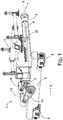
- FIG Fig. 1 and 2 Two overall perspective views of the embodiment of a device 1 according to the invention are shown in FIG Fig. 1 and 2 shown.
- the device 1 comprises as basic components a trolley 2, rolling elements 3, a rotatable support member 7, a rotary shaft 5, a transmission rod 8 and a holder 6.
- the trolley 2 is along a transport direction R by means of rolling elements 3 and rotatable support member 7 movable, z. B. along rails or other guide means, which are arranged next to a dip tank.
- the rotary shaft 5 is arranged horizontally and attached at a first end at right angles to the trolley 2.
- the holder 6 is rotatably mounted in the region 11 on the rotary shaft 5 approximately centrally thereof and can be rotated with this about its longitudinal axis X.
- the rotary shaft 5 is hollow.
- a transmission means carried out in the embodiment as a transmission rod 8, guided and also mounted horizontally and at right angles to the transport direction R.
- a bearing 10 for stabilizing the transmission means.
- a rotatable support member 7 is provided at a second end of the rotary shaft 5.
- a drive 4 is provided, which is in communication with the rolling elements 3 and the rotatable support member 7. The drive 4 is located on the trolley 2 and is translated by means of belt transmission 9 both to the rolling elements 3 and to the support member 7, wherein a connection to the support member 7 by the guided inside the rotary shaft 5 and mounted transfer means.
- the drive 4 drives the rolling elements 3 and the rotatable support member 7 simultaneously, whereby the device 1 along the transport direction R is quietly continuously movable.
- Fig. 3 shows a further device according to the invention 1.
- the device 1 comprises only one rolling element 3 and is therefore preferably suitable for dip painting of small or light bodies such as cars.
- the weight of a car body can be easily carried by a driven rolling element 3 and the driven support element 7.
- two support rollers 14 are arranged on the trolley, which are not driven.
- the support rollers 14 are rotatably mounted, so that the trolley 2 can drive along the transport direction R to curves.
- Prefers These are stored in the transport direction R in front of and behind the rolling element 3 at the two ends of the trolley 2 on the underside, to distribute the weight of the device 1 itself and a mounted on this body as evenly as possible.
- the in the Fig. 3 shown device 1 further comprises a second transmission means 15, which translates from a pivot drive on the trolley 2 to the holder 6, so that they can perform a pivoting movement. Due to the pivoting movement in the immersion bath, it is possible to remove air bubbles from the paint on the body.
- the second transmission means 15 is guided only to a position below the holder 6, which is usually arranged approximately in a center of the rotary shaft 5 at this.
- the second transmission means 15 is hollow, with the transmission rod 8 guided therein.
- the second transmission means 15 with the transmission rod 8 is guided in the hollow rotary shaft 5 in order to keep the device 1 as compact as possible.
- a device 1 according to the embodiment of Fig. 1 and 2 is equipped with the additional rotary actuator, provided that a stability of these is not reduced by the further movement of a heavy object.
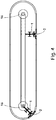
- Fig. 4 shows a treatment path with curves, on which a device 1 according to Fig. 3 can be used.
- two devices 1 are thereby placed on the treatment line, that the trolley 2 is arranged on an outside part of this.
- This has the consequence that this or attached to this rolling element 3 in a curve must cover a longer distance than the support member 7.
- a planetary gear 16 is arranged in an inner region of the curve. The freely revolving support rollers 14 align themselves according to the curves.
- FIG. 5 A possible training variant of the freely revolving support rollers 14 is in Fig. 5 shown.
- the support rollers 14 are rotatably mounted on an underside of the trolley 2. At the other end of the support rollers 14, which is aligned towards the treatment section, these have at least one pair of guide rollers 17.
- two pairs of guide rollers 17 are shown and arranged on both sides of a shorter part of an L-shaped rail of the treatment section and run freely with.
- a device 1 according to Fig. 1 and 2 is preferably used when dip coating large bodies.
- the device 1 is moved along a treatment path which, for example, also comprises a treatment basin with a lacquer.
- the device 1 is moved to the treatment basin, wherein the drive 4 drives both the rolling elements 3 and the rotatable support member 7.
- the drive 12 is set in motion and thus also the rotary shaft 5 to turn the holder 6 together with the body so that the body is screwed into the treatment tank.
- both the rolling elements 3 and the rotatable support element 7 are decelerated simultaneously by the drive 4 or the associated motor, so that the rotary shaft 5 is optimally stabilized during the screwing process.
- a device 1 according to Fig. 3 can also on a treatment course with curves, such.
- Fig. 4 shown are used, since these movably mounted support rollers 14, which are passively moved.
- a dipping operation works in principle similar to that of a device 1 according to Fig. 1 and 2 , with the difference that with this device 1 in addition a pivoting movement can be performed. If the body is immersed in the treatment tank, the holder 6 is controlled via the second transmission means 15 such that it pivots the body attached thereto.
Landscapes
- Coating Apparatus (AREA)
- Spray Control Apparatus (AREA)
- Automobile Manufacture Line, Endless Track Vehicle, Trailer (AREA)
Description
- Die Erfindung betrifft eine Vorrichtung nach dem Oberbegriff des Anspruchs 1 zum Befördern eines Gegenstandes, insbesondere einer Karosserie, entlang einer Behandlungsstrecke, umfassend einen in einer Transportrichtung entlang der Behandlungsstrecke bewegbaren Transportwagen mit einem oder mehreren Rollelementen und mit einem Antrieb sowie eine Drehwelle, auf der eine Halterung für den zu behandelnden Gegenstand befestigt ist, wobei die Drehwelle an einem ersten Ende am Transportwagen gelagert ist und am zweiten Ende ein drehbares Stützelement aufweist.
- Des Weiteren betrifft die Erfindung eine Verwendung einer derartigen Vorrichtung.
- Ferner betrifft die vorliegende Erfindung ein Verfahren nach dem Oberbegriff des Anspruchs 12 zum Befördern eines Gegenstandes, insbesondere einer Karosserie, entlang einer Behandlungsstrecke, wobei ein Transportwagen mit einem oder mehreren Rollelementen und mit einem Antrieb sowie einer Drehwelle, auf der eine Halterung für den zu behandelnden Gegenstand befestigt ist, wobei die Drehwelle an einem ersten Ende am Transportwagen gelagert ist und am zweiten Ende ein drehbares Stützelement aufweist, in einer Transportrichtung entlang der Behandlungsstrecke bewegt wird.
- Eine oben erwähnte Behandlungsstrecke umfasst zumindest eine, meist mehrere Stationen zur Oberflächenbehandlung eines Gegenstandes, wie z. B. einer Fahrzeugkarosserie. Bei den Stationen kann es sich z. B. um Tauchbäder mit verschiedenen Behandlungsflüssigkeiten handeln, in welche die Karosserien zum Lackieren eingetaucht werden. Dabei sollten auch große Karosserien möglichst stabil, platzsparend und kostengünstig transportierbar sein.
- Gemäß dem Stand der Technik sind verschiedene Anlagen zum Befördern von Karosserien entlang einer Behandlungsstrecke bekannt.
- Die
WO 2011/123878 A1 offenbart eine Vorrichtung nach dem Oberbegriff des Anspruchs 1 und ein Verfahren zum Tauchlackieren einer Karosserie nach dem Oberbegriff des Anspruchs 12. - Vorrichtungen zum Befördern von Karosserien von Pkws umfassen üblicherweise einen Transportwagen, an dem eine Drehwelle mit einer Halterung für den zu behandelnden Gegenstand befestigt ist und an deren dem Transportwagen gegenüberliegenden Ende ein Stützelement passiv mitbewegt wird. Beim Befördern einer größeren Karosserie, wie beispielsweise einer Karosserie eines Busses oder Lkws, ergibt sich durch dieses passive Ende der Drehwelle ein Stabilisierungsproblem. Das passiv geführte Stützelement kann die auftretenden Kräfte nicht ausgleichen bzw. das große Gewicht nicht lagestabil abstützen. Eine Vorrichtung zum Befördern von Autos bzw. kleinerer Gegenstände ist somit für größere Gegenstände nicht geeignet bzw. mit einem größeren Gegenstand unmanövrierbar. Des Weiteren weist die Halterung meist einen oder mehrere Kippmechanismen auf. Infolgedessen wird die Halterung beim Drehen der Drehwelle nicht nur mitgedreht, sondern auch gleichzeitig gekippt. Bei großen Karosserien hat das zur Folge, dass das passive Stützelement die Kräfte, die beim Eintauchvorgang und somit beim Drehen der Drehwelle und Kippen bzw. Eindrehen der Halterung auftreten, nicht halten kann. Daher kann es dabei zu einem unerwünschten Verkippen des zu behandelnden Gegenstandes und insbesondere der Drehwelle kommen. Um diesen Nachteil der Vorrichtung auszugleichen, wird üblicherweise anstatt des passiven Stützelements ein zweiter Transportwagen am zweiten Ende der Drehwelle angebracht. Eine solche Vorrichtung hat aber den Nachteil, dass diese sehr groß ist und damit viel Platz beansprucht. Durch den zweiten Transportwagen ist die Vorrichtung weiter schwer zugänglich für z. B. Absprühvorgänge oder etwaige Reparaturarbeiten. Außerdem ist durch den zweiten Transportwagen ein nicht unwesentlicher Mehraufwand an Steuerungselektronik notwendig.
- Aufgabe der Erfindung ist es, die mit den oben beschriebenen Vorrichtungen verbundenen Nachteile zu beseitigen oder zumindest zu verringern. Insbesondere liegt der Erfindung die Aufgabe zugrunde, eine Vorrichtung sowie ein Verfahren der eingangs genannten Art anzugeben, mit der bzw. dem große Gegenstände wie Karosserien von Bussen und Lkws platzsparend, jedoch mit ausreichender Stabilisierung entlang einer Behandlungsstrecke befördert werden können. Dies soll mit einer einfachen und somit kostengünstigen, aber effizienten Fördervorrichtung erreicht werden.
- Die Lösung dieser Aufgabe erfolgt durch eine Vorrichtung mit den Merkmalen des Anspruchs 1 und durch ein Verfahren mit den Merkmalen des Anspruchs 12.
- Mit der Erfindung erzielte Vorteile sind insbesondere darin zu sehen, dass die Vorrichtung nur einen Transportwagen aufweist und somit platzsparend und kostengünstig ist. Sollen große Karosserien befördert und tauchlackiert werden, umfasst die Vorrichtung dazu bevorzugt mehrere Rollelemente, um das große Gewicht gleichmäßig und stabilisierend zu verteilen. Durch das, mit demselben Antrieb wie die Rollelemente angetriebene, drehbare Stützelement kann die Vorrichtung ausreichend stabilisiert werden. Die Kräfte, welche bei der Beschleunigung bzw. beim Abbremsen des Transportwagens auftreten, werden somit auf beide Enden der Drehwelle verteilt. Ein ungewolltes Verkippen der Halterung mitsamt dem zu behandelnden Gegenstand beim Abbremsen und Eintauchen wird dadurch vermieden, dass das drehbare Stützelement auch abbremsbar und damit arretierbar ist.
- Alternativ können insbesondere für kleinere Karosserien wie Pkws nur ein Rollelement und das drehbare Stützelement angetrieben sein, wobei das Rollelement etwa mittig an einer Unterseite des Transportwagens angeordnet ist. Auch bei dieser Anordnung sind die beim Eintauchen oder Abbremsen auftretenden Kräfte auf beide Enden der Drehwelle verteilt.
- Ein weiterer Vorteil ist, dass das drehbare Stützelement mittels eines Übertragungsmittels, insbesondere einer Übertragungsstange, mit dem Antrieb verbunden ist und somit direkt vom gleichen Antrieb wie die Rollelemente angesteuert und angetrieben werden kann.
- Zweckmäßigerweise ist die Drehwelle hohl und das Übertragungsmittel im Inneren der hohlen Drehwelle geführt, sodass kein weiterer Platz für das Übertragungsmittel erforderlich ist.
- Mit Vorteil ist vorgesehen, dass sich vorzugsweise im Bereich unter der Halterung in der hohlen Drehwelle eine Lagerung zur Stabilisierung des Übertragungsmittels befindet, welche ein Durchbiegen bzw. nach längerer Anwendungszeit ein mögliches Brechen dieser verhindert.
- Des Weiteren ist es von Vorteil, dass der Antrieb mittels Riemenübersetzung mit den Rollelementen und dem drehbaren Stützelement in Verbindung steht. Somit sollte die Übersetzung ohne Schmiermittel auskommen, was eine Verunreinigung der Behandlungsflüssigkeit mit Öl oder dergleichen verhindert. Ein Riemenantrieb kann auch nicht korrodieren. Somit verringern sich die Wartungskosten.
- Allgemein ist es aber auch möglich, andere Zugmittel anstelle von Riemen einzusetzen. Beispielsweise können Ketten eingesetzt werden. Insbesondere bei schweren Lasten können Ketten einen Vorteil darstellen, zumal Ketten gegebenenfalls auch schmiermittelfrei betreibbar sind.
- Es hat sich bewährt, dass die Halterung für den zu behandelnden Gegenstand drehfest an der Drehwelle befestigt und zusammen mit der Drehwelle um deren Längsachse drehbar ist. Eine solche Bauweise wirkt wiederum auf die gesamte Vorrichtung stabilisierend; die Halterung kann beim Drehen der Drehwelle nicht kippen und ist somit auch für große Gegenstände stabil.
- Gemäß einer Ausführungsvariante ist es weiter von Vorteil, dass zum Antreiben der Drehwelle ein eigener Antrieb vorgesehen ist, welcher sich auf dem Transportwagen befindet und mittels Riemen zur Drehwelle übersetzt. Somit kann die Drehung der Drehwelle völlig unabhängig von der Bewegung des Transportwagens erfolgen.
- Es ist von Vorteil, wenn am Transportwagen zumindest eine Stützrolle angeordnet ist, wobei die Stützrolle drehbar gelagert ist. Erfindungsgemäß können dabei zwei Stützrollen vorgesehen sein, welche in Transportrichtung vor und hinter dem Rollelement angeordnet drehbar gelagert sind, sodass der Transportwagen auf einer Behandlungsstrecke einsetzbar ist, welche Kurven umfasst. Erfindungsgemäß kann vorgesehen sein, dass die Stützrolle an einer unteren Seite Führungsrollen aufweist, welche links- und rechtsseitig einer L-förmig ausgebildeten Schiene der Behandlungsstrecke gelagert sind. An einer oberen Seite ist die Stützrolle dabei drehbar am Transportwagen gelagert.
- Vorteilhaft ist weiter, wenn ein zweites Übertragungsmittel vom Transportwagen bis zu einer Position unterhalb der Halterung geführt ist. Das zweite Übertragungsmittel übersetzt dabei von einem am Transportwagen gelagerten Schwenkantrieb zur Halterung, sodass diese eine daran befestigte Karosserie im Tauchbad schwenken kann, um etwaige Luftbläschen oder dergleichen, welche sich beim Tauchvorgang bilden, von der Karosserie zu entfernen.
- Günstig ist es dabei, wenn das zweite Übertragungsmittel im Inneren der Drehwelle geführt ist, um die Vorrichtung möglichst kompakt zu halten.
- Sehr effektiv ist es weiter, wenn das zweite Übertragungsmittel hohl ausgebildet ist und in dessen Innerem die Übertragungsstange geführt ist, um platzsparend zu agieren.
- Eine Verwendung der erfindungsgemäßen Vorrichtung erfolgt typischerweise beim Tauchlackieren von Karosserien.
- Die Lösung der verfahrensmäßigen Aufgabe erfolgt durch die Merkmale des Anspruchs 12.
- Verfahrensmäßig wird bevorzugt, dass das drehbare Stützelement beim Drehen der Drehwelle gemeinsam mit zumindest einem Rollelement abgebremst wird.
- Es ist von Vorteil, wenn die Halterung beim Tauchvorgang geschwenkt wird, um etwaige Luftbläschen oder dergleichen vom Lack eines zu lackierenden Gegenstandes zu entfernen. Zur Steuerung dieser Schwenkbewegung wird im Inneren der Drehwelle ein zweites Übertragungsmittel von einem am Transportwagen gelagerten Schwenkantrieb bis zu einer Position unter der Halterung geführt, welches hohl ausgebildet ist. Im hohlen zweiten Übertragungsmittel wird die Übertragungsstange geführt, um die Vorrichtung kompakt zu halten.
- Weitere Merkmale, Vorteile und Wirkungen der Erfindung ergeben sich anhand der nachfolgend dargestellten Ausführungsbeispiele. In den Zeichnungen, auf welche dabei Bezug genommen wird, zeigen:
-
Fig.1 und2 je eine perspektivische Darstellung einer erfindungsgemäßen Vorrichtung mit aufgeschnittener Ansicht der Drehwelle; -
Fig. 3 eine weitere erfindungsgemäße Vorrichtung mit aufgeschnittener Drehwelle; -
Fig. 4 eine Behandlungsstrecke; -
Fig. 5 eine Ansicht einer Stützrolle einer Vorrichtung gemäßFig. 3 . - Zwei perspektivische Gesamtansichten der Ausführungsform einer erfindungsgemäßen Vorrichtung 1 sind in
Fig. 1 und2 dargestellt. Die Vorrichtung 1 umfasst als Grundbestandteile einen Transportwagen 2, Rollelemente 3, ein drehbares Stützelement 7, eine Drehwelle 5, eine Übertragungsstange 8 und eine Halterung 6. Der Transportwagen 2 ist entlang einer Transportrichtung R mittels Rollelementen 3 und drehbarem Stützelement 7 bewegbar, z. B. entlang von Schienen oder anderen Führungsmitteln, die neben einem Tauchbecken angeordnet sind. Die Drehwelle 5 ist waagrecht angeordnet und an einem ersten Ende im rechten Winkel am Transportwagen 2 befestigt. Die Halterung 6 ist drehfest im Bereich 11 an der Drehwelle 5 etwa mittig derselben angebracht und kann mit dieser um deren Längsachse X gedreht werden. Die Drehwelle 5 ist hohl. Im Inneren der Drehwelle 5 ist ein Übertragungsmittel, im Ausführungsbeispiel ausgeführt als Übertragungsstange 8, geführt und ebenfalls waagrecht und im rechten Winkel zur Transportrichtung R angebracht. Vorzugsweise in einem Bereich unter der Halterung 6 in der hohlen Drehwelle 5 befindet sich eine Lagerung 10 zur Stabilisierung des Übertragungsmittels. An einem zweiten Ende der Drehwelle 5 ist ein drehbares Stützelement 7 vorgesehen. Ferner ist ein Antrieb 4 vorgesehen, der mit den Rollelementen 3 und dem drehbaren Stützelement 7 in Verbindung steht. Der Antrieb 4 befindet sich auf dem Transportwagen 2 und wird mittels Riemenübersetzung 9 sowohl zu den Rollelementen 3 als auch zum Stützelement 7 übersetzt, wobei eine Verbindung zum Stützelement 7 durch das im Inneren der Drehwelle 5 geführte und gelagerte Übertragungsmittel erfolgt. Ein eigener Antrieb 12, welcher ebenfalls am Transportwagen 2 positioniert ist, übersetzt wiederum mittels Riemen 13 zur Drehwelle 5. Der Antrieb 4 treibt die Rollelemente 3 und das drehbare Stützelement 7 gleichzeitig an, wodurch die Vorrichtung 1 entlang der Transportrichtung R ruhig laufend bewegbar ist. -
Fig. 3 zeigt eine weitere erfindungsgemäße Vorrichtung 1. In diesem Ausführungsbeispiel umfasst die Vorrichtung 1 nur ein Rollelement 3 und ist deshalb bevorzugt zum Tauchlackieren von kleinen bzw. leichten Karosserien wie Pkws geeignet. Das Gewicht einer Pkw-Karosserie kann problemlos von einem angetriebenen Rollelement 3 und dem angetriebenen Stützelement 7 getragen werden. Zusätzlich zum angetriebenen Rollelement 3 sind am Transportwagen 2 zwei Stützrollen 14 angeordnet, welche nicht angetrieben sind. Die Stützrollen 14 sind dabei drehbar gelagert, sodass der Transportwagen 2 entlang der Transportrichtung R um Kurven fahren kann. Bevorzugt sind diese in Transportrichtung R vor und hinter dem Rollelement 3 an den zwei Enden des Transportwagens 2 an dessen Unterseite gelagert, um das Gewicht der Vorrichtung 1 selbst und einer an dieser angebrachten Karosserie möglichst gleichmäßig zu verteilen. - Die in der
Fig. 3 gezeigte Vorrichtung 1 umfasst weiter ein zweites Übertragungsmittel 15, welches von einem Schwenkantrieb auf dem Transportwagen 2 zur Halterung 6 übersetzt, damit diese eine Schwenkbewegung ausführen kann. Durch die Schwenkbewegung im Tauchbad ist es möglich, Lüftbläschen aus dem Lack an der Karosserie zu entfernen. Zweckmäßig ist das zweite Übertragungsmittel 15 nur bis zu einer Position unterhalb der Halterung 6 geführt, welche üblicherweise etwa in einer Mitte der Drehwelle 5 an dieser angeordnet ist. Das zweite Übertragungsmittel 15 ist hohl ausgebildet, wobei die Übertragungsstange 8 darin geführt ist. Das zweite Übertragungsmittel 15 mit der Übertragungsstange 8 ist in der hohlen Drehwelle 5 geführt, um die Vorrichtung 1 möglichst kompakt zu halten. Auch eine Vorrichtung 1 gemäß dem Ausführungsbeispiel derFig. 1 und2 ist mit dem zusätzlichen Schwenkantrieb ausstattbar, vorausgesetzt, dass eine Stabilität dieser durch die weitere Bewegung eines schweren Gegenstandes nicht herabgesetzt ist. -
Fig. 4 zeigt eine Behandlungsstrecke mit Kurven, auf welcher eine Vorrichtung 1 gemäßFig. 3 einsetzbar ist. InFig. 4 sind zwei Vorrichtungen 1 dabei so auf der Behandlungsstrecke platziert, dass der Transportwagen 2 an einem außenseitigen Teil dieser angeordnet ist. Das hat zur Folge, dass dieser bzw. das an diesem angebrachte Rollelement 3 in einer Kurve eine längere Strecke zurücklegen muss, als das Stützelement 7. Um diesen Längenunterschied auszugleichen, ist in einem Innenbereich der Kurve ein Umlaufrädergetriebe 16 angeordnet. Die frei mitlaufenden Stützrollen 14 richten sich selbstständig entsprechend der Kurven aus. - Eine mögliche Ausbildungsvariante der frei mitlaufenden Stützrollen 14 ist in
Fig. 5 gezeigt. Die Stützrollen 14 sind an einer Unterseite des Transportwagens 2 drehbar gelagert. Am anderen Ende der Stützrollen 14, welches zur Behandlungsstrecke hin ausgerichtet ist, weisen diese zumindest ein Paar Führungsrollen 17 auf. InFig. 5 sind zwei Paar Führungsrollen 17 gezeigt und an beiden Seiten eines kürzeren Teils einer L-förmig ausgebildeten Schiene der Behandlungsstrecke angeordnet und laufen frei mit. - Eine Vorrichtung 1 gemäß
Fig. 1 und2 wird bevorzugt beim Tauchlackieren von großen Karosserien eingesetzt. Dabei wird die Vorrichtung 1 entlang einer Behandlungsstrecke bewegt, die beispielsweise auch ein Behandlungsbecken mit einem Lack umfasst. Die Vorrichtung 1 wird zum Behandlungsbecken bewegt, wobei der Antrieb 4 sowohl die Rollelemente 3 als auch das drehbare Stützelement 7 antreibt. Beim Eintauchvorgang der Halterung 6 mit dem zu behandelnden Gegenstand wird der Antrieb 12 in Bewegung versetzt und damit auch die Drehwelle 5, um die Halterung 6 samt Karosserie so zu drehen, dass die Karosserie in das Behandlungsbecken eingedreht wird. Dabei bzw. zuvor werden sowohl die Rollelemente 3 als auch das drehbare Stützelement 7 gleichzeitig vom Antrieb 4 bzw. dem zugehörigen Motor abgebremst, sodass die Drehwelle 5 beim Eindrehvorgang optimal stabilisiert ist. - Eine Vorrichtung 1 gemäß
Fig. 3 kann auch auf einer Behandlungsstrecke mit Kurven, wie z. B. inFig. 4 dargestellt, eingesetzt werden, da diese bewegbar gelagerte Stützrollen 14 aufweist, welche passiv mitbewegt werden. Ein Eintauchvorgang funktioniert prinzipiell ähnlich dem einer Vorrichtung 1 gemäßFig. 1 und2 , mit dem Unterschied, dass mit dieser Vorrichtung 1 zusätzlich eine Schwenkbewegung ausgeführt werden kann. Wird die Karosserie in das Behandlungsbecken eingetaucht, wird über das zweite Übertragungsmittel 15 die Halterung 6 so angesteuert, dass diese die daran angebrachte Karosserie schwenkt.
Claims (14)
- Vorrichtung (1) zum Befördern eines Gegenstandes, insbesondere einer Karosserie, entlang einer Behandlungsstrecke, umfassend einen in einer Transportrichtung (R) entlang der Behandlungsstrecke bewegbaren Transportwagen (2) mit einem oder mehreren Rollelementen (3) und mit einem Antrieb (4) sowie eine Drehwelle (5), auf der eine Halterung (6) für den zu behandelnden Gegenstand befestigt ist, wobei die Drehwelle (5) an einem ersten Ende am Transportwagen (2) gelagert ist und am zweiten Ende ein drehbares Stützelement (7) aufweist, wobei ein Übertragungsmittel, insbesondere eine Übertragungsstange (8), vorgesehen ist, welche den Antrieb (4) mit dem drehbaren Stützelement (7) verbindet, dadurch gekennzeichnet, dass der Antrieb (4) zumindest ein Rollelement (3) und das drehbare Stützelement (7) gemeinsam antreibt.
- Vorrichtung (1) nach Anspruch 1, dadurch gekennzeichnet, dass die Drehwelle (5) hohl ist und das Übertragungsmittel im Inneren der hohlen Drehwelle (5) geführt ist.
- Vorrichtung (1) nach Anspruch 1 oder 2, dadurch gekennzeichnet, dass sich vorzugsweise in einem Bereich unter der Halterung (6) in der hohlen Drehwelle (5) eine Lagerung (10) zur Stabilisierung des Übertragungsmittels befindet.
- Vorrichtung (1) nach einem der Ansprüche 1 bis 3, dadurch gekennzeichnet, dass der Antrieb (4) mittels einer Riemenübersetzung (9) mit den Rollelementen (3) und dem drehbaren Stützelement (7) in Verbindung steht.
- Vorrichtung (1) nach einem der Ansprüche 1 bis 4, dadurch gekennzeichnet, dass die Halterung (6) für den zu behandelnden Gegenstand drehfest an der Drehwelle (5) befestigt und zusammen mit der Drehwelle (5) um deren Längsachse (X) drehbar ist.
- Vorrichtung (1) nach Anspruch 5, dadurch gekennzeichnet, dass zum Antreiben der Drehwelle (5) ein eigener Antrieb (12) vorgesehen ist, welcher sich auf dem Transportwagen (2) befindet und mittels Riemen (13) zur Drehwelle (5) übersetzt.
- Vorrichtung (1) nach einem der Ansprüche 1 bis 6, dadurch gekennzeichnet, dass am Transportwagen (2) zumindest eine Stützrolle (14) angeordnet ist, wobei die Stützrolle (14) drehbar gelagert ist.
- Vorrichtung (1) nach einem der Ansprüche 1 bis 7, dadurch gekennzeichnet, dass ein zweites Übertragungsmittel (15) vom Transportwagen (2) bis zu einer Position unterhalb der Halterung (6) geführt ist.
- Vorrichtung (1) nach Anspruch 8, dadurch gekennzeichnet, dass das zweite Übertragungsmittel (15) im Inneren der Drehwelle (5) geführt ist.
- Vorrichtung (1) nach Anspruch 9, dadurch gekennzeichnet, dass das zweite Übertragungsmittel (15) hohl ausgebildet ist und in dessen Innerem die Übertragungsstange (8) geführt ist.
- Verwendung einer Vorrichtung (1) nach einem der Ansprüche 1 bis 10 zum Tauchlackieren von Karosserien.
- Verfahren zum Befördern eines Gegenstandes, insbesondere einer Karosserie, entlang einer Behandlungsstrecke, wobei ein Transportwagen (2) mit einem oder mehreren Rollelementen (3) und mit einem Antrieb (4) sowie einer Drehwelle (5), auf der eine Halterung (6) für den zu behandelnden Gegenstand befestigt ist, wobei die Drehwelle (5) an einem ersten Ende am Transportwagen (2) gelagert ist und am zweiten Ende ein drehbares Stützelement (7) aufweist, wobei ein Übertragungsmittel, insbesondere eine Übertragungsstange (8), vorgesehen ist, welche den Antrieb (4) mit dem drehbaren Stützelement (7) verbindet, in einer Transportrichtung (R) entlang der Behandlungsstrecke bewegt wird, dadurch gekennzeichnet, dass zumindest ein Rollelement (3) und das drehbare Stützelement (7) durch den Antrieb (4) gemeinsam angetrieben werden.
- Verfahren nach Anspruch 12, dadurch gekennzeichnet, dass das drehbare Stützelement (7) beim Drehen der Drehwelle (5) gemeinsam mit zumindest einem Rollelement (3) abgebremst wird.
- Verfahren nach Anspruch 12 oder 13, dadurch gekennzeichnet, dass die Halterung (6) beim Tauchvorgang geschwenkt wird.
Applications Claiming Priority (2)
| Application Number | Priority Date | Filing Date | Title |
|---|---|---|---|
| ATA50180/2013A AT514190B1 (de) | 2013-03-15 | 2013-03-15 | Vorrichtung und Verfahren zum Tauchlackieren großer Karosserien |
| PCT/AT2014/050065 WO2014138768A1 (de) | 2013-03-15 | 2014-03-14 | VORRICHTUNG UND VERFAHREN ZUM TAUCHLACKIEREN GROßER KAROSSERIEN |
Publications (2)
| Publication Number | Publication Date |
|---|---|
| EP2969867A1 EP2969867A1 (de) | 2016-01-20 |
| EP2969867B1 true EP2969867B1 (de) | 2019-07-10 |
Family
ID=50548986
Family Applications (1)
| Application Number | Title | Priority Date | Filing Date |
|---|---|---|---|
| EP14719193.6A Active EP2969867B1 (de) | 2013-03-15 | 2014-03-14 | Vorrichtung und verfahren zum tauchlackieren grosser karosserien |
Country Status (5)
| Country | Link |
|---|---|
| EP (1) | EP2969867B1 (de) |
| CN (1) | CN105026291B (de) |
| AT (1) | AT514190B1 (de) |
| HU (1) | HUE045707T2 (de) |
| WO (1) | WO2014138768A1 (de) |
Families Citing this family (3)
| Publication number | Priority date | Publication date | Assignee | Title |
|---|---|---|---|---|
| CN104438003A (zh) * | 2014-12-09 | 2015-03-25 | 常州市骠马工业机器人系统工程有限公司 | 一种汽车涂装前处理用设备 |
| CN104816928B (zh) * | 2015-05-13 | 2017-07-28 | 中国汽车工业工程有限公司 | 用于输送物料的翻转机 |
| AT520118B1 (de) * | 2017-06-30 | 2021-06-15 | Alex Fehberger | Transportvorrichtung und Verfahren zum Tauchlackieren |
Family Cites Families (9)
| Publication number | Priority date | Publication date | Assignee | Title |
|---|---|---|---|---|
| DE10100377B4 (de) * | 2001-01-05 | 2006-03-02 | Eisenmann Maschinenbau Gmbh & Co. Kg | Anlage zum Behandeln, insbesondere zum Lackieren, von Gegenständen, insbesondere Fahrzeugkarosserien |
| DE10210941B4 (de) * | 2002-03-13 | 2006-09-14 | Eisenmann Maschinenbau Gmbh & Co. Kg | Anlage zum Behandeln von Gegenständen |
| DE10258132A1 (de) * | 2002-12-02 | 2004-06-17 | Dürr Automotion Gmbh | Vorrichtung und Verfahren zur Oberflächenbehandlung von Werkstücken |
| DE102004024614A1 (de) * | 2004-05-18 | 2005-12-08 | Dürr Systems GmbH | Anlage und Verfahren zum Befördern von Werkstücken entlang einer Behandlungsstrecke |
| DE102006038684B4 (de) * | 2006-08-17 | 2008-07-10 | Eisenmann Anlagenbau Gmbh & Co. Kg | Anlage zum Behandeln, insbesondere zum kataphoretischen Tauchlackieren, von Gegenständen |
| CN102120298A (zh) * | 2010-01-12 | 2011-07-13 | 力山工业股份有限公司 | 用于加工机具的基座总成 |
| DE102010004974B4 (de) * | 2010-01-18 | 2021-06-10 | Eisenmann Se | Fördersystem zum Transport von Gegenständen und Tauchbehandlungsanlage mit einem solchen |
| EP2556004B1 (de) * | 2010-04-09 | 2014-12-03 | Alex Fehberger | Vorrichtung zum befördern eines zu behandelnden gegenstandes |
| JP5560974B2 (ja) * | 2010-07-06 | 2014-07-30 | 株式会社ダイフク | 走行型浸漬処理装置 |
-
2013
- 2013-03-15 AT ATA50180/2013A patent/AT514190B1/de active
-
2014
- 2014-03-14 CN CN201480011798.8A patent/CN105026291B/zh active Active
- 2014-03-14 EP EP14719193.6A patent/EP2969867B1/de active Active
- 2014-03-14 WO PCT/AT2014/050065 patent/WO2014138768A1/de not_active Ceased
- 2014-03-14 HU HUE14719193A patent/HUE045707T2/hu unknown
Non-Patent Citations (1)
| Title |
|---|
| None * |
Also Published As
| Publication number | Publication date |
|---|---|
| AT514190A1 (de) | 2014-10-15 |
| HUE045707T2 (hu) | 2020-01-28 |
| WO2014138768A1 (de) | 2014-09-18 |
| CN105026291B (zh) | 2018-03-09 |
| AT514190B1 (de) | 2021-04-15 |
| CN105026291A (zh) | 2015-11-04 |
| EP2969867A1 (de) | 2016-01-20 |
Similar Documents
| Publication | Publication Date | Title |
|---|---|---|
| EP1343709B2 (de) | Anlage zur behandlung, insbesondere zum lackieren, von gegenständen, insbesondere von fahrzeugkarosserien | |
| EP2242712B1 (de) | Hängebahnsystem und tauchbehandlungsanlage mit einem solchen | |
| DE10103837B4 (de) | Anlage zum Behandeln, insbesondere zum Lackieren von Gegenständen, insbesondere von Fahrzeugkarosserien | |
| EP2231492B1 (de) | Tauchbehandlungsanlage | |
| EP2242711B1 (de) | Hängebahnsystem, tauchbehandlungsanlage mit einem solchen, und verwendung dieses hängebahnsystems | |
| EP2678256B1 (de) | Anlage zur tauchbehandlung von gegenständen | |
| DE10100377B4 (de) | Anlage zum Behandeln, insbesondere zum Lackieren, von Gegenständen, insbesondere Fahrzeugkarosserien | |
| AT509670B1 (de) | Vorrichtung zum befördern eines zu behandelnden gegenstandes | |
| EP2526038B1 (de) | Fördersystem zum transport von gegenständen und tauchbehandlungsanlage mit einem solchen | |
| EP3105157B1 (de) | Tauchbehandlungsanlage mit einer einrichtung zum drehen der zu behandelnden gegenstände | |
| DE29724558U1 (de) | Vorrichtung zur Oberflächenbehandlung von Werkstücken | |
| DE102012003271B4 (de) | Tauchbehandlungsanlage | |
| EP2556004B1 (de) | Vorrichtung zum befördern eines zu behandelnden gegenstandes | |
| DE10210942B4 (de) | Anlage zum Behandeln, insbesondere zum kataphoretischen Tauchlackieren, von Gegenständen, insbesondere von Fahrzeugkarosserien | |
| DE102007063061A1 (de) | Tauchbehandlungsanlage | |
| WO2014138768A1 (de) | VORRICHTUNG UND VERFAHREN ZUM TAUCHLACKIEREN GROßER KAROSSERIEN | |
| DE10211214C1 (de) | Anlage zum Behandeln, insbesondere zum kataphoretischen Tauchlackieren, von Gegenständen, insbesondere von Fahrzeugkarosserien | |
| WO2016050516A1 (de) | Fördersystem für werkstücke | |
| EP3078616A1 (de) | Tauchbehandlungsanlage zum tauchbehandeln von gegenständen |
Legal Events
| Date | Code | Title | Description |
|---|---|---|---|
| PUAI | Public reference made under article 153(3) epc to a published international application that has entered the european phase |
Free format text: ORIGINAL CODE: 0009012 |
|
| 17P | Request for examination filed |
Effective date: 20150513 |
|
| AK | Designated contracting states |
Kind code of ref document: A1 Designated state(s): AL AT BE BG CH CY CZ DE DK EE ES FI FR GB GR HR HU IE IS IT LI LT LU LV MC MK MT NL NO PL PT RO RS SE SI SK SM TR |
|
| AX | Request for extension of the european patent |
Extension state: BA ME |
|
| DAX | Request for extension of the european patent (deleted) | ||
| GRAP | Despatch of communication of intention to grant a patent |
Free format text: ORIGINAL CODE: EPIDOSNIGR1 |
|
| INTG | Intention to grant announced |
Effective date: 20160916 |
|
| GRAJ | Information related to disapproval of communication of intention to grant by the applicant or resumption of examination proceedings by the epo deleted |
Free format text: ORIGINAL CODE: EPIDOSDIGR1 |
|
| STAA | Information on the status of an ep patent application or granted ep patent |
Free format text: STATUS: REQUEST FOR EXAMINATION WAS MADE |
|
| INTC | Intention to grant announced (deleted) | ||
| STAA | Information on the status of an ep patent application or granted ep patent |
Free format text: STATUS: EXAMINATION IS IN PROGRESS |
|
| 17Q | First examination report despatched |
Effective date: 20170228 |
|
| GRAP | Despatch of communication of intention to grant a patent |
Free format text: ORIGINAL CODE: EPIDOSNIGR1 |
|
| STAA | Information on the status of an ep patent application or granted ep patent |
Free format text: STATUS: GRANT OF PATENT IS INTENDED |
|
| INTG | Intention to grant announced |
Effective date: 20180307 |
|
| GRAS | Grant fee paid |
Free format text: ORIGINAL CODE: EPIDOSNIGR3 |
|
| RAP1 | Party data changed (applicant data changed or rights of an application transferred) |
Owner name: AUTOMOTIVE ENGINEERING CORPORATION Owner name: SCIVIC ENGINEERING CORPORATION |
|
| RIN1 | Information on inventor provided before grant (corrected) |
Inventor name: FEHBERGER, ALEX |
|
| GRAA | (expected) grant |
Free format text: ORIGINAL CODE: 0009210 |
|
| STAA | Information on the status of an ep patent application or granted ep patent |
Free format text: STATUS: THE PATENT HAS BEEN GRANTED |
|
| AK | Designated contracting states |
Kind code of ref document: B1 Designated state(s): AL AT BE BG CH CY CZ DE DK EE ES FI FR GB GR HR HU IE IS IT LI LT LU LV MC MK MT NL NO PL PT RO RS SE SI SK SM TR |
|
| REG | Reference to a national code |
Ref country code: GB Ref legal event code: FG4D Free format text: NOT ENGLISH |
|
| REG | Reference to a national code |
Ref country code: CH Ref legal event code: EP Ref country code: AT Ref legal event code: REF Ref document number: 1153356 Country of ref document: AT Kind code of ref document: T Effective date: 20190715 |
|
| REG | Reference to a national code |
Ref country code: IE Ref legal event code: FG4D Free format text: LANGUAGE OF EP DOCUMENT: GERMAN |
|
| REG | Reference to a national code |
Ref country code: DE Ref legal event code: R096 Ref document number: 502014012177 Country of ref document: DE |
|
| REG | Reference to a national code |
Ref country code: NL Ref legal event code: MP Effective date: 20190710 |
|
| REG | Reference to a national code |
Ref country code: LT Ref legal event code: MG4D |
|
| REG | Reference to a national code |
Ref country code: HU Ref legal event code: AG4A Ref document number: E045707 Country of ref document: HU |
|
| PG25 | Lapsed in a contracting state [announced via postgrant information from national office to epo] |
Ref country code: LT Free format text: LAPSE BECAUSE OF FAILURE TO SUBMIT A TRANSLATION OF THE DESCRIPTION OR TO PAY THE FEE WITHIN THE PRESCRIBED TIME-LIMIT Effective date: 20190710 Ref country code: PT Free format text: LAPSE BECAUSE OF FAILURE TO SUBMIT A TRANSLATION OF THE DESCRIPTION OR TO PAY THE FEE WITHIN THE PRESCRIBED TIME-LIMIT Effective date: 20191111 Ref country code: FI Free format text: LAPSE BECAUSE OF FAILURE TO SUBMIT A TRANSLATION OF THE DESCRIPTION OR TO PAY THE FEE WITHIN THE PRESCRIBED TIME-LIMIT Effective date: 20190710 Ref country code: SE Free format text: LAPSE BECAUSE OF FAILURE TO SUBMIT A TRANSLATION OF THE DESCRIPTION OR TO PAY THE FEE WITHIN THE PRESCRIBED TIME-LIMIT Effective date: 20190710 Ref country code: HR Free format text: LAPSE BECAUSE OF FAILURE TO SUBMIT A TRANSLATION OF THE DESCRIPTION OR TO PAY THE FEE WITHIN THE PRESCRIBED TIME-LIMIT Effective date: 20190710 Ref country code: NL Free format text: LAPSE BECAUSE OF FAILURE TO SUBMIT A TRANSLATION OF THE DESCRIPTION OR TO PAY THE FEE WITHIN THE PRESCRIBED TIME-LIMIT Effective date: 20190710 Ref country code: BG Free format text: LAPSE BECAUSE OF FAILURE TO SUBMIT A TRANSLATION OF THE DESCRIPTION OR TO PAY THE FEE WITHIN THE PRESCRIBED TIME-LIMIT Effective date: 20191010 Ref country code: NO Free format text: LAPSE BECAUSE OF FAILURE TO SUBMIT A TRANSLATION OF THE DESCRIPTION OR TO PAY THE FEE WITHIN THE PRESCRIBED TIME-LIMIT Effective date: 20191010 |
|
| PG25 | Lapsed in a contracting state [announced via postgrant information from national office to epo] |
Ref country code: ES Free format text: LAPSE BECAUSE OF FAILURE TO SUBMIT A TRANSLATION OF THE DESCRIPTION OR TO PAY THE FEE WITHIN THE PRESCRIBED TIME-LIMIT Effective date: 20190710 Ref country code: AL Free format text: LAPSE BECAUSE OF FAILURE TO SUBMIT A TRANSLATION OF THE DESCRIPTION OR TO PAY THE FEE WITHIN THE PRESCRIBED TIME-LIMIT Effective date: 20190710 Ref country code: LV Free format text: LAPSE BECAUSE OF FAILURE TO SUBMIT A TRANSLATION OF THE DESCRIPTION OR TO PAY THE FEE WITHIN THE PRESCRIBED TIME-LIMIT Effective date: 20190710 Ref country code: IS Free format text: LAPSE BECAUSE OF FAILURE TO SUBMIT A TRANSLATION OF THE DESCRIPTION OR TO PAY THE FEE WITHIN THE PRESCRIBED TIME-LIMIT Effective date: 20191110 Ref country code: RS Free format text: LAPSE BECAUSE OF FAILURE TO SUBMIT A TRANSLATION OF THE DESCRIPTION OR TO PAY THE FEE WITHIN THE PRESCRIBED TIME-LIMIT Effective date: 20190710 Ref country code: GR Free format text: LAPSE BECAUSE OF FAILURE TO SUBMIT A TRANSLATION OF THE DESCRIPTION OR TO PAY THE FEE WITHIN THE PRESCRIBED TIME-LIMIT Effective date: 20191011 |
|
| PG25 | Lapsed in a contracting state [announced via postgrant information from national office to epo] |
Ref country code: TR Free format text: LAPSE BECAUSE OF FAILURE TO SUBMIT A TRANSLATION OF THE DESCRIPTION OR TO PAY THE FEE WITHIN THE PRESCRIBED TIME-LIMIT Effective date: 20190710 |
|
| PG25 | Lapsed in a contracting state [announced via postgrant information from national office to epo] |
Ref country code: DK Free format text: LAPSE BECAUSE OF FAILURE TO SUBMIT A TRANSLATION OF THE DESCRIPTION OR TO PAY THE FEE WITHIN THE PRESCRIBED TIME-LIMIT Effective date: 20190710 Ref country code: EE Free format text: LAPSE BECAUSE OF FAILURE TO SUBMIT A TRANSLATION OF THE DESCRIPTION OR TO PAY THE FEE WITHIN THE PRESCRIBED TIME-LIMIT Effective date: 20190710 Ref country code: PL Free format text: LAPSE BECAUSE OF FAILURE TO SUBMIT A TRANSLATION OF THE DESCRIPTION OR TO PAY THE FEE WITHIN THE PRESCRIBED TIME-LIMIT Effective date: 20190710 Ref country code: RO Free format text: LAPSE BECAUSE OF FAILURE TO SUBMIT A TRANSLATION OF THE DESCRIPTION OR TO PAY THE FEE WITHIN THE PRESCRIBED TIME-LIMIT Effective date: 20190710 Ref country code: IT Free format text: LAPSE BECAUSE OF FAILURE TO SUBMIT A TRANSLATION OF THE DESCRIPTION OR TO PAY THE FEE WITHIN THE PRESCRIBED TIME-LIMIT Effective date: 20190710 |
|
| PG25 | Lapsed in a contracting state [announced via postgrant information from national office to epo] |
Ref country code: SM Free format text: LAPSE BECAUSE OF FAILURE TO SUBMIT A TRANSLATION OF THE DESCRIPTION OR TO PAY THE FEE WITHIN THE PRESCRIBED TIME-LIMIT Effective date: 20190710 Ref country code: SK Free format text: LAPSE BECAUSE OF FAILURE TO SUBMIT A TRANSLATION OF THE DESCRIPTION OR TO PAY THE FEE WITHIN THE PRESCRIBED TIME-LIMIT Effective date: 20190710 Ref country code: IS Free format text: LAPSE BECAUSE OF FAILURE TO SUBMIT A TRANSLATION OF THE DESCRIPTION OR TO PAY THE FEE WITHIN THE PRESCRIBED TIME-LIMIT Effective date: 20200224 Ref country code: CZ Free format text: LAPSE BECAUSE OF FAILURE TO SUBMIT A TRANSLATION OF THE DESCRIPTION OR TO PAY THE FEE WITHIN THE PRESCRIBED TIME-LIMIT Effective date: 20190710 |
|
| REG | Reference to a national code |
Ref country code: DE Ref legal event code: R097 Ref document number: 502014012177 Country of ref document: DE |
|
| PLBE | No opposition filed within time limit |
Free format text: ORIGINAL CODE: 0009261 |
|
| STAA | Information on the status of an ep patent application or granted ep patent |
Free format text: STATUS: NO OPPOSITION FILED WITHIN TIME LIMIT |
|
| PG2D | Information on lapse in contracting state deleted |
Ref country code: IS |
|
| 26N | No opposition filed |
Effective date: 20200603 |
|
| PG25 | Lapsed in a contracting state [announced via postgrant information from national office to epo] |
Ref country code: SI Free format text: LAPSE BECAUSE OF FAILURE TO SUBMIT A TRANSLATION OF THE DESCRIPTION OR TO PAY THE FEE WITHIN THE PRESCRIBED TIME-LIMIT Effective date: 20190710 |
|
| PG25 | Lapsed in a contracting state [announced via postgrant information from national office to epo] |
Ref country code: MC Free format text: LAPSE BECAUSE OF FAILURE TO SUBMIT A TRANSLATION OF THE DESCRIPTION OR TO PAY THE FEE WITHIN THE PRESCRIBED TIME-LIMIT Effective date: 20190710 |
|
| REG | Reference to a national code |
Ref country code: CH Ref legal event code: PL |
|
| REG | Reference to a national code |
Ref country code: BE Ref legal event code: MM Effective date: 20200331 |
|
| PG25 | Lapsed in a contracting state [announced via postgrant information from national office to epo] |
Ref country code: LU Free format text: LAPSE BECAUSE OF NON-PAYMENT OF DUE FEES Effective date: 20200314 |
|
| PG25 | Lapsed in a contracting state [announced via postgrant information from national office to epo] |
Ref country code: LI Free format text: LAPSE BECAUSE OF NON-PAYMENT OF DUE FEES Effective date: 20200331 Ref country code: CH Free format text: LAPSE BECAUSE OF NON-PAYMENT OF DUE FEES Effective date: 20200331 Ref country code: FR Free format text: LAPSE BECAUSE OF NON-PAYMENT OF DUE FEES Effective date: 20200331 Ref country code: IE Free format text: LAPSE BECAUSE OF NON-PAYMENT OF DUE FEES Effective date: 20200314 |
|
| PG25 | Lapsed in a contracting state [announced via postgrant information from national office to epo] |
Ref country code: BE Free format text: LAPSE BECAUSE OF NON-PAYMENT OF DUE FEES Effective date: 20200331 |
|
| GBPC | Gb: european patent ceased through non-payment of renewal fee |
Effective date: 20200314 |
|
| PG25 | Lapsed in a contracting state [announced via postgrant information from national office to epo] |
Ref country code: GB Free format text: LAPSE BECAUSE OF NON-PAYMENT OF DUE FEES Effective date: 20200314 |
|
| REG | Reference to a national code |
Ref country code: AT Ref legal event code: MM01 Ref document number: 1153356 Country of ref document: AT Kind code of ref document: T Effective date: 20200314 |
|
| PG25 | Lapsed in a contracting state [announced via postgrant information from national office to epo] |
Ref country code: AT Free format text: LAPSE BECAUSE OF NON-PAYMENT OF DUE FEES Effective date: 20200314 |
|
| PG25 | Lapsed in a contracting state [announced via postgrant information from national office to epo] |
Ref country code: MT Free format text: LAPSE BECAUSE OF FAILURE TO SUBMIT A TRANSLATION OF THE DESCRIPTION OR TO PAY THE FEE WITHIN THE PRESCRIBED TIME-LIMIT Effective date: 20190710 Ref country code: CY Free format text: LAPSE BECAUSE OF FAILURE TO SUBMIT A TRANSLATION OF THE DESCRIPTION OR TO PAY THE FEE WITHIN THE PRESCRIBED TIME-LIMIT Effective date: 20190710 |
|
| PG25 | Lapsed in a contracting state [announced via postgrant information from national office to epo] |
Ref country code: MK Free format text: LAPSE BECAUSE OF FAILURE TO SUBMIT A TRANSLATION OF THE DESCRIPTION OR TO PAY THE FEE WITHIN THE PRESCRIBED TIME-LIMIT Effective date: 20190710 |
|
| PGFP | Annual fee paid to national office [announced via postgrant information from national office to epo] |
Ref country code: DE Payment date: 20260320 Year of fee payment: 13 |
|
| PGFP | Annual fee paid to national office [announced via postgrant information from national office to epo] |
Ref country code: HU Payment date: 20260305 Year of fee payment: 13 |