EP2969877B1 - Asymmetrische und gelenkte scheiben für aufzugsanlagen mit verdrillten riemen - Google Patents
Asymmetrische und gelenkte scheiben für aufzugsanlagen mit verdrillten riemen Download PDFInfo
- Publication number
- EP2969877B1 EP2969877B1 EP13877545.7A EP13877545A EP2969877B1 EP 2969877 B1 EP2969877 B1 EP 2969877B1 EP 13877545 A EP13877545 A EP 13877545A EP 2969877 B1 EP2969877 B1 EP 2969877B1
- Authority
- EP
- European Patent Office
- Prior art keywords
- sheave
- belt
- belts
- elevator system
- group
- Prior art date
- Legal status (The legal status is an assumption and is not a legal conclusion. Google has not performed a legal analysis and makes no representation as to the accuracy of the status listed.)
- Active
Links
Images




Classifications
-
- B—PERFORMING OPERATIONS; TRANSPORTING
- B66—HOISTING; LIFTING; HAULING
- B66B—ELEVATORS; ESCALATORS OR MOVING WALKWAYS
- B66B15/00—Main component parts of mining-hoist winding devices
- B66B15/02—Rope or cable carriers
- B66B15/04—Friction sheaves; "Koepe" pulleys
-
- B—PERFORMING OPERATIONS; TRANSPORTING
- B66—HOISTING; LIFTING; HAULING
- B66B—ELEVATORS; ESCALATORS OR MOVING WALKWAYS
- B66B7/00—Other common features of elevators
- B66B7/06—Arrangements of ropes or cables
-
- B—PERFORMING OPERATIONS; TRANSPORTING
- B66—HOISTING; LIFTING; HAULING
- B66B—ELEVATORS; ESCALATORS OR MOVING WALKWAYS
- B66B9/00—Kinds or types of lifts in, or associated with, buildings or other structures
-
- F—MECHANICAL ENGINEERING; LIGHTING; HEATING; WEAPONS; BLASTING
- F16—ENGINEERING ELEMENTS AND UNITS; GENERAL MEASURES FOR PRODUCING AND MAINTAINING EFFECTIVE FUNCTIONING OF MACHINES OR INSTALLATIONS; THERMAL INSULATION IN GENERAL
- F16H—GEARING
- F16H55/00—Elements with teeth or friction surfaces for conveying motion; Worms, pulleys or sheaves for gearing mechanisms
- F16H55/32—Friction members
- F16H55/36—Pulleys
-
- F—MECHANICAL ENGINEERING; LIGHTING; HEATING; WEAPONS; BLASTING
- F16—ENGINEERING ELEMENTS AND UNITS; GENERAL MEASURES FOR PRODUCING AND MAINTAINING EFFECTIVE FUNCTIONING OF MACHINES OR INSTALLATIONS; THERMAL INSULATION IN GENERAL
- F16H—GEARING
- F16H55/00—Elements with teeth or friction surfaces for conveying motion; Worms, pulleys or sheaves for gearing mechanisms
- F16H55/32—Friction members
- F16H55/36—Pulleys
- F16H2055/363—Pulleys with special means or properties for lateral tracking of the flexible members running on the pulley, e.g. with crowning to keep a belt on track
Definitions
- the subject matter disclosed herein relates to elevator systems driven by belts. More specifically, the subject disclosure relates sheave configurations from elevator systems driven by belts.
- Elevator systems utilize one or more belts, such as coated steel belts operably connected to an elevator car, and driven by a motor to propel the elevator car along a hoistway.
- Coated steel belts in particular include a plurality of wires located at least partially within a jacket material. The plurality of wires is often arranged into one or more strands and the strands are then arranged into one or more cords. In an exemplary belt construction, a plurality of cords is typically arranged equally spaced within a jacket in a longitudinal direction.
- the motor drives a sheave, in this case a traction sheave, over which the coated steel belt is routed.
- the belt gains traction at the traction sheave, such that rotation of the traction sheave consequently drives movement of the elevator car.
- the system may further include other sheaves around which the coated steel belts are routed to change direction of the coated steel belt.
- the roping arrangement of belts is such that sheaves are used to rotate or twist the belts as required.
- FIG. 9 is a single belt 100 system the sheaves 102 may be arranged as shown such that a pure twist of the belt 100 is achieved, with no draw of the belt 100 between sheaves 102. Referring now to FIG.
- the sheave 102 arrangement in systems with multiple, parallel belts 100, for example, two belts 100, the sheave 102 arrangement imparts draw, as well as twist between the sheaves 102.
- the arrangement produces pure twist in one belt 100, while also producing twist and draw in the other belt 100.
- the draw results in tracking problems for the belt 100, causing the belt to move laterally on a sheave crown 104 and hit flanges 106 of the sheave. This causes excessive wear on the belt 100, especially at edges thereof, and also causes belt-sheave noise and uneven stress on the belt 100 which leads to premature belt 100 failure.
- one sheave pair 108 is at a fixed location in the hoistway, while the other sheave pair 110 is located at an elevator car.
- the distance between sheave pairs 108 and 110 changes, so that the draw angle also changes.
- the draw angle increases, Tracking deviation is therefore not constant, and becomes more severe as the sheave pairs 108 and 110 move closer together.
- US 2007/252121 A1 discloses an elevator sheave that includes a belt guiding surface having a surface profile along at least a portion of the belt guiding surface.
- the surface profile preferably is defined by an nth order polynomial equation where n is a number greater than 2.
- the reference point is a central point along the width of the belt guiding surface.
- a central portion of the surface profile preferably is aligned to be generally parallel with the central axis of the sheave body.
- US 2010/236869 A1 describes a load bearing member for supporting an elevator car has a plurality of tension members that bear the weight and counterweight of the elevator car. The plurality of tension members extends along a length. An outer cover envelopes the plurality of tension members and has a first surface and a second surface.
- an elevator system in one embodiment, includes an elevator car located in a hoistway.
- One or more belts are operably connected to the elevator car to drive and/or support the elevator car along the hoistway.
- the one or more belts are routed over one or more sheaves.
- the one or more sheaves include an outer surface rotatable about a central axis and a flange located at at least one lateral end of the sheave.
- the sheave further includes a tracking compensator to limit lateral motion of the belt along the outer surface to prevent the belt from contacting the flange.
- the tracking compensator comprises an asymmetrical crown on the outer surface of the sheave.
- a first sheave radius at a first lateral end of the sheave is greater than a second sheave radius at a second lateral end of the sheave.
- the belt travels at substantially a lateral center of the sheave.
- the one or more belts are two or more belts.
- the plurality of sheaves are arranged in sheave groups each sheave of a sheave group guiding a separate belt of the two or more belts.
- each sheave of a sheave group includes an asymmetrical crown on the outer surface of the sheave such that a first sheave radius at a first lateral end of the sheave is greater than a second sheave radius at a second lateral end of the sheave.
- a direction of crown of a first sheave of the sheave group is substantially the same as a direction of crown of a second sheave of the sheave group.
- a first central axis of a first sheave of the sheave group intersects a second central axis of a second sheave of the sheave group at a sheave angle.
- the sheave angle is configured to normalize a stress distribution on the belts.
- first sheave and the second sheave are connected by a steered shaft to have a same rotational speed.
- an elevator system in another embodiment, includes an elevator car located in a hoistway and two or more belts operably connected to the elevator car to drive and/or support the elevator car along the hoistway.
- the system further includes a plurality of sheave groups over which the two or more belts are routed.
- Each sheave of a sheave group includes an outer surface rotatable about a central axis and a flange located at at least one lateral end of the sheave.
- the sheave further includes a tracking compensator to limit lateral motion of the belt along the outer surface to prevent the belt from contacting the flange.
- the two or more belts twist and draw between a first sheave group and a second sheave group.
- a draw angle of a first belt of the two or more belts is equal to a draw angle of a second belt of the two or more belts.
- the elevator system has a 4:1 roping arrangement.
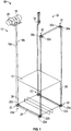
- FIG. 1 Shown in FIG. 1 is a schematic of an embodiment of a traction elevator system 10.
- the elevator system 10 includes an elevator car 12 operatively suspended or supported in a hoistway 14 with two or more belts 16.
- the arrangement shown is referred to a 4:1 roping arrangement, though the structure disclosed herein may be utilized in elevator systems 10 having other roping arrangements.
- a first belt 16a and a second belt 16b extend from a traction sheave 18 which is driven by a machine 20.
- the first belt 16a and the second belt 16b support the elevator car 12 via support sheave pairs 22 secured to the elevator car 12, for example, at a car bottom 24.
- the support sheave pairs 22 comprise support shaves 22a and 22b, which are coaxial in their rotation.
- the system of FIG. 1 includes two sheave pairs 22 to transfer the first belt 16a and the second belt 16b under and across the elevator car 12 from a drive side 26 of the hoistway 14 (the side closest to the machine 20) to a non-drive side 28 of the hoistway 14 (the side furthest from the machine 20).
- the first belt 16a and second belt 16b are extended from the support sheave pairs 22 up and around a transfer sheave pair 30 comprising a first transfer sheave 30a and a second transfer sheave 30b.
- the transfer sheave pair 30 is secured at a fixed position in the hoistway 14, for example at or near a top 32 of the hoistway 14. Due to the orientation of the transfer sheave pair 30, it is necessary for the first belt 16a and second belt 16b to twist, in some embodiments about 90 degrees, between the support sheave pair 22 and the transfer sheave pair 30. More detail regarding the twist of belts 16a, 16b, and the configuration of transfer sheaves 30a and 30b will be provided below.
- the first belt 16a and second belt 16b are routed over a second transfer sheave pair 30 and down the hoistway 14 to another support sheave pair 22 at the car bottom 24, between which the first belt 16a and second belt 16b twist again to match the orientation of the support sheave pair 22.
- the belts 16a and 16b pass under the elevator car 12 from the non-drive side 28 to the drive side 26 then up the hoistway 14 to a termination point.
- the belts 16a and 16b are coated steel belts.
- Each belt 16 is constructed of a plurality of wires 36 (e.g. twisted into one or more strands 38 and/or cords 40 as shown in FIG. 3 ) in a jacket 42.
- the belt 16 has an aspect ratio greater than one (i.e. belt width is greater than belt thickness).
- the belts 16 are constructed to have sufficient flexibility when passing over the sheave to provide low bending stresses, meet belt life requirements and have smooth operation, while being sufficiently strong to be capable of meeting strength requirements for suspending and/or driving the elevator car 12.
- the jacket 42 could be any suitable material, including a single material, multiple materials, two or more layers using the same or dissimilar materials, and/or a film.
- the jacket 42 could be a polymer, such as an elastomer, applied to the cords 40 using, for example, an extrusion or a mold wheel process.
- the jacket 42 could be a woven fabric that engages and/or integrates the cords 40.
- the jacket 42 could be one or more of the previously mentioned alternatives in combination.
- the jacket 42 can substantially retain the cords 40 therein.
- the phrase substantially retain means that the jacket 42 has sufficient engagement with the cords 40 to transfer torque from the machine 20 through the jacket 42 to the cords 40 to drive movement of the elevator car 12.
- the jacket 42 could completely envelop the cords 40 (such as shown in FIG. 2 ), substantially envelop the cords 40, or at least partially envelop the cords 40.
- FIG. 4 a view looking down the hoistway 14 at transfer sheave pair 30 and support sheave pair 22 is shown.
- the transfer sheave pair 30 and the support sheave pair 22 are positioned such that a first draw angle 44a of belt 16a between support sheave 22a and transfer sheave 30a is equal and opposite to a second draw angle 44b of belt 16b between support sheave 22b and transfer sheave 30b.
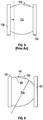
- sheaves 102 are crowned symmetrically between flanges 106 is an effort to guide belts 100 toward a center of the sheave 102.
- the belts 100 tend to reside and travel on one side of the symmetrically crowned sheave 102.
- first transfer sheave 30a and belt 16a shown is an embodiment of first transfer sheave 30a and belt 16a. It is to be appreciated, however, that the following disclosure may be applied to any of the sheaves and belts in the elevator system 10 to realize the benefit thereof. Since draw in the system 10 causes the belt 16a to ride to one side of a peak 46 (where the sheave 30a has the largest radius), the sheave 30a includes a tracking compensator, in this embodiment an asymmetrical crown 48, so that peak 46 is not equidistant between flanges 50, but such that a position where belt 16a tends to ride is equidistant between the flanges 50.
- a tracking compensator in this embodiment an asymmetrical crown 48
- the crown shown in FIG. 6 is a circular crown 48 having a substantially continuous radius, but in other embodiments other crown shapes may be utilized, such as those with multiple radii or polynomial shapes.
- pairs of asymmetrically crowned sheaves can be utilized to form transfer sheave pairs 30, and/or support sheave pairs 22.
- the transfer sheaves 30a and 30b may be configured to have equal and opposite crown such that belts 16a and 16b remain substantially centered on transfer sheaves 30a and 30b.
- support sheaves 22a and 22b may similarly have equal and opposite
- the tracking compensator includes a common jointed or steered shaft 52 about which the first transfer sheave 30a and second transfer sheave 30b rotate.
- the steered shaft 52 offsets the transfer sheaves 30a and 30b such that a sheave angle 54 exists between the first transfer sheave 30a and the second transfer sheave 30b.
- the sheave angle 54 is up to about 10 degrees.
- the sheave angle 54 normalizes a stress distribution on the belts 16a and 16b over the first transfer sheave 30a and second transfer sheave 30b.
- first support sheave 22a and second support sheave 22b may be similarly configured to normalize stress distribution in the belts 16a and 16b.
Landscapes
- Engineering & Computer Science (AREA)
- General Engineering & Computer Science (AREA)
- Automation & Control Theory (AREA)
- Structural Engineering (AREA)
- Mechanical Engineering (AREA)
- Lift-Guide Devices, And Elevator Ropes And Cables (AREA)
- Cage And Drive Apparatuses For Elevators (AREA)
Claims (12)
- Aufzugsanlage (10), umfassend:eine Aufzugskabine (12), die in einem Schacht (14) angeordnet ist;zwei oder mehr Riemen (16), die mit der Aufzugskabine (12) wirkverbunden sind, um die Aufzugskabine (12) entlang des Schachtes (14) anzutreiben und/oder zu stützen,eine Vielzahl von Scheibengruppen, über welche die zwei oder mehr Riemen (16) gelenkt werden, wobei jede Scheibe (18; 22; 30) einer Scheibengruppe Folgendes beinhaltet:eine äußere Oberfläche, die um eine Mittelachse gedreht werden kann;einen Flansch (50), der an zumindest einem lateralen Ende der Scheibe (18; 22; 30) angeordnet ist; undeinen Nachverfolgungskompensator, um eine laterale Bewegung des Riemens (16) entlang der äußeren Fläche zu begrenzen, um zu verhindern, dass der Riemen (16) den Flansch (42) berührt;wobei jede Scheibe (18; 22; 30) einer Scheibengruppe einen getrennten Riemen (16) der zwei oder mehr Riemen führt;dadurch gekennzeichnet, dass eine erste Mittelachse einer ersten Scheibe (18; 22; 30) der Scheibengruppe eine zweite Mittelachse einer zweiten Scheibe (18; 22; 30) der Scheibengruppe in einem Scheibenwinkel (54) schneidet.
- Aufzugsanlage (10) nach Anspruch 1, wobei der Nachverfolgungskompensator eine asymmetrische Krone (48) auf der äußeren Oberfläche der Scheibe (18; 22; 30) umfasst.
- Aufzugsanlage nach Anspruch 2, wobei ein erster Scheibenradius an einem ersten lateralen Ende (50) der Scheibe (18; 22; 30) größer als ein zweiter Scheibenradius an einem zweiten lateralen Ende (50) der Scheibe (18; 22; 30) ist.
- Aufzugsanlage (10) nach Anspruch 2 oder 3, wobei sich der Riemen (16) in im Wesentlichen einer Mitte der Scheibe in einer lateralen Richtung der Scheibe (18; 22; 30) bewegt.
- Aufzugsanlage nach Anspruch 1, wobei jede Scheibe (18; 22; 30) einer Scheibengruppe eine asymmetrische Krone (48) der äußeren Oberfläche der Scheibe (18; 22; 30) beinhaltet, sodass ein erster Scheibenradius an einem ersten lateralen Ende (50) der Scheibe größer als ein zweiter Scheibenradius an einem zweiten lateralen Ende (50) der Scheibe (18; 22; 30) ist.
- Aufzugsanlage (10) nach Anspruch 5, wobei eine Asymmetrierichtung einer Krone einer ersten Scheibe der Scheibengruppe im Wesentlichen die gleiche ist wie eine Asymmetrierichtung einer Krone einer zweiten Scheibe der Scheibengruppe.
- Aufzugsanlage (10) nach Anspruch 5, wobei eine Asymmetrierichtung einer Krone einer ersten Scheibe der Scheibengruppe im Wesentlichen einer Asymmetrierichtung einer Krone einer zweiten Scheibe der Scheibengruppe entgegengesetzt ist.
- Aufzugsanlage (10) nach einem der Ansprüche 1 bis 7, wobei der Scheibenwinkel (54) konfiguriert ist, um eine Lastverteilung auf den Riemen (16) zu normalisieren.
- Aufzugsanlage (10) nach Anspruch 1, wobei sich die erste Scheibe (18a; 22a; 30a) und die zweite Scheibe (18b; 22b; 30b) auf einer gelenkten Welle befinden.
- Aufzugsanlage (10) nach Anspruch 1, wobei die zwei oder mehr Riemen (16) zwischen einer ersten Scheibengruppe und einer zweiten Scheibengruppe verdrillt und gezogen werden.
- Aufzugsanlage nach Anspruch 10, wobei ein Zugwinkel (44a) eines ersten Riemens (16a) der zwei oder mehr Riemen (16) gleich einem Zugwinkel (44b) eines zweiten Riemens (16b) der zwei oder mehr Riemen (16) ist.
- Aufzugsanlage nach Anspruch 1, wobei die Aufzugsanlage eine Verseilungsanordung im Verhältnis 4:1 aufweist.
Applications Claiming Priority (1)
| Application Number | Priority Date | Filing Date | Title |
|---|---|---|---|
| PCT/US2013/032155 WO2014142979A1 (en) | 2013-03-15 | 2013-03-15 | Asymmetric and steered sheaves for twisted multi-belt elevator systems |
Publications (3)
| Publication Number | Publication Date |
|---|---|
| EP2969877A1 EP2969877A1 (de) | 2016-01-20 |
| EP2969877A4 EP2969877A4 (de) | 2016-12-07 |
| EP2969877B1 true EP2969877B1 (de) | 2020-10-07 |
Family
ID=51537340
Family Applications (1)
| Application Number | Title | Priority Date | Filing Date |
|---|---|---|---|
| EP13877545.7A Active EP2969877B1 (de) | 2013-03-15 | 2013-03-15 | Asymmetrische und gelenkte scheiben für aufzugsanlagen mit verdrillten riemen |
Country Status (4)
| Country | Link |
|---|---|
| US (2) | US9643819B2 (de) |
| EP (1) | EP2969877B1 (de) |
| CN (1) | CN105209367B (de) |
| WO (1) | WO2014142979A1 (de) |
Families Citing this family (5)
| Publication number | Priority date | Publication date | Assignee | Title |
|---|---|---|---|---|
| US9643819B2 (en) | 2013-03-15 | 2017-05-09 | Otis Elevator Company | Asymmetric and steered sheaves for twisted multi-belt elevator systems |
| ES2751305T3 (es) * | 2016-06-07 | 2020-03-31 | Kone Corp | Cuerda de ascensor, disposición de ascensor, y ascensor |
| US10549953B2 (en) | 2017-07-17 | 2020-02-04 | Thyssenkrupp Elevator Ag | Elevator belt position tracking system |
| CN108153949B (zh) * | 2017-12-14 | 2021-07-23 | 新疆金风科技股份有限公司 | 非对称结构的驱动组件中传动带的受力计算方法及装置 |
| CN113828523A (zh) * | 2021-08-20 | 2021-12-24 | 北京裹裹科技有限责任公司 | 一种分拣小车及分拣系统 |
Family Cites Families (24)
| Publication number | Priority date | Publication date | Assignee | Title |
|---|---|---|---|---|
| US1316972A (en) * | 1919-09-23 | prentiss | ||
| US1265110A (en) * | 1917-08-09 | 1918-05-07 | George W Prentiss & Company | Spool device. |
| US1361250A (en) * | 1918-05-06 | 1920-12-07 | Chicago Steel & Wire Company | Reel |
| US2966065A (en) * | 1959-06-19 | 1960-12-27 | Adamson Stephens Mfg Co | Belt conveyors |
| US3288338A (en) * | 1964-04-29 | 1966-11-29 | United States Steel Corp | Apparatus for automatically centering elongated objects |
| US4196864A (en) * | 1978-12-07 | 1980-04-08 | Cole Frederick W | Line winding tool set |
| US4589601A (en) * | 1985-05-28 | 1986-05-20 | Gte Products Corporation | Method of winding braze strip material |
| DE3838724A1 (de) * | 1987-12-07 | 1989-06-22 | Schmid Hans Armin | Vorrichtung zum fuehren eines bombierten bandes |
| EP0356798B1 (de) * | 1988-08-12 | 1993-12-29 | Bando Chemical Industries, Limited | Bandgetriebe und Riemenscheibe |
| ATE305896T1 (de) * | 2001-01-04 | 2005-10-15 | Wittur Ag | Getriebeloser seilaufzug mit doppelt umschlungenen treibscheibenantrieb |
| JP4683863B2 (ja) * | 2003-06-19 | 2011-05-18 | インベンテイオ・アクテイエンゲゼルシヤフト | 可動式牽引手段による負荷輸送用の昇降機 |
| US7156209B2 (en) * | 2004-05-28 | 2007-01-02 | Inventio Ag | Elevator roping arrangement |
| US7806238B2 (en) * | 2004-07-12 | 2010-10-05 | Inventio Ag | Elevator and pulley assembly for use in an elevator |
| ATE547373T1 (de) * | 2004-08-04 | 2012-03-15 | Otis Elevator Co | Rillenscheibe zur verwendung in einem aufzugssystem |
| EP1832543B1 (de) | 2004-12-27 | 2014-03-26 | Mitsubishi Denki Kabushiki Kaisha | Aufzugsvorrichtung |
| JP4207893B2 (ja) * | 2004-12-28 | 2009-01-14 | ブラザー工業株式会社 | ベルトユニットおよび画像形成装置 |
| JP4861996B2 (ja) * | 2005-02-25 | 2012-01-25 | オーチス エレベータ カンパニー | 角度を形成するアンダースラング式ローピング配置を有するエレベータかご |
| JP2008243294A (ja) * | 2007-03-27 | 2008-10-09 | Fujifilm Corp | テープリール、記録テープカートリッジ、マシンリール及びドライブ装置 |
| BRPI0721977A2 (pt) * | 2007-09-27 | 2014-03-18 | Otis Elevator Company | Membro de suporte de carga para suportar um carro de elevador, e, elevador |
| US20090194505A1 (en) | 2008-01-24 | 2009-08-06 | Microcontinuum, Inc. | Vacuum coating techniques |
| US9643819B2 (en) | 2013-03-15 | 2017-05-09 | Otis Elevator Company | Asymmetric and steered sheaves for twisted multi-belt elevator systems |
| JP6002842B2 (ja) * | 2013-05-28 | 2016-10-05 | 京セラドキュメントソリューションズ株式会社 | 金属ベルトを備える駆動機構 |
| EP3071504B1 (de) * | 2013-11-22 | 2020-06-24 | Otis Elevator Company | Zwischenrolle oder ablenkscheibe für aufzugssystem |
| CN105764829B (zh) * | 2013-11-25 | 2019-12-20 | 奥的斯电梯公司 | 用于电梯系统的底板 |
-
2013
- 2013-03-15 US US14/777,058 patent/US9643819B2/en active Active
- 2013-03-15 WO PCT/US2013/032155 patent/WO2014142979A1/en not_active Ceased
- 2013-03-15 CN CN201380076566.6A patent/CN105209367B/zh active Active
- 2013-03-15 EP EP13877545.7A patent/EP2969877B1/de active Active
-
2017
- 2017-01-20 US US15/411,202 patent/US9932205B2/en active Active
Non-Patent Citations (1)
| Title |
|---|
| None * |
Also Published As
| Publication number | Publication date |
|---|---|
| CN105209367A (zh) | 2015-12-30 |
| US20160039639A1 (en) | 2016-02-11 |
| EP2969877A1 (de) | 2016-01-20 |
| US9643819B2 (en) | 2017-05-09 |
| US20170129743A1 (en) | 2017-05-11 |
| WO2014142979A1 (en) | 2014-09-18 |
| CN105209367B (zh) | 2017-09-29 |
| EP2969877A4 (de) | 2016-12-07 |
| US9932205B2 (en) | 2018-04-03 |
Similar Documents
| Publication | Publication Date | Title |
|---|---|---|
| US9932205B2 (en) | Asymmetric and steered sheaves for twisted multi-belt elevator systems | |
| EP3071504B1 (de) | Zwischenrolle oder ablenkscheibe für aufzugssystem | |
| US10773929B2 (en) | Sheave for elevator system | |
| HK1222162A1 (zh) | 电梯 | |
| US10005642B2 (en) | Elevator and elevator rope | |
| US9663328B2 (en) | Elevator system belt | |
| EP2969876B1 (de) | Treibscheibe für aufzugssystem | |
| EP3126277B1 (de) | Gerillter riemen für ein aufzugssystem | |
| CN104418214B (zh) | 电梯 | |
| US20180179023A1 (en) | Increased traction of elevator system belt | |
| FI126915B (fi) | Hihnamainen vetoelin ja menetelmä vetoelimen valmistamiseksi sekä mainitun vetoelimen käyttö hississä ja mainitulla vetoelimellä varustettu hissi | |
| CN113446379A (zh) | 绳轮、曳引轮、电梯驱动机械和电梯 | |
| HK1215562A1 (zh) | 电梯 | |
| CN117509353A (zh) | 用于曳引轮电梯的悬挂装置 | |
| HK40056727A (en) | Rope wheel, traction wheel, elevator drive machinery and elevator | |
| HK1216743A1 (zh) | 电梯 | |
| HK1257118A1 (en) | Elevator system suspension member | |
| HK1109383A1 (en) | Sheave and assembly for use in an elevator system | |
| HK1207618B (zh) | 电梯 | |
| HK1109383B (en) | Sheave and assembly for use in an elevator system |
Legal Events
| Date | Code | Title | Description |
|---|---|---|---|
| PUAI | Public reference made under article 153(3) epc to a published international application that has entered the european phase |
Free format text: ORIGINAL CODE: 0009012 |
|
| 17P | Request for examination filed |
Effective date: 20151013 |
|
| AK | Designated contracting states |
Kind code of ref document: A1 Designated state(s): AL AT BE BG CH CY CZ DE DK EE ES FI FR GB GR HR HU IE IS IT LI LT LU LV MC MK MT NL NO PL PT RO RS SE SI SK SM TR |
|
| AX | Request for extension of the european patent |
Extension state: BA ME |
|
| DAX | Request for extension of the european patent (deleted) | ||
| REG | Reference to a national code |
Ref country code: DE Ref legal event code: R079 Ref document number: 602013073185 Country of ref document: DE Free format text: PREVIOUS MAIN CLASS: B66B0011060000 Ipc: B66B0015040000 |
|
| A4 | Supplementary search report drawn up and despatched |
Effective date: 20161104 |
|
| RIC1 | Information provided on ipc code assigned before grant |
Ipc: B66B 15/04 20060101AFI20161028BHEP |
|
| RAP1 | Party data changed (applicant data changed or rights of an application transferred) |
Owner name: OTIS ELEVATOR COMPANY |
|
| STAA | Information on the status of an ep patent application or granted ep patent |
Free format text: STATUS: EXAMINATION IS IN PROGRESS |
|
| 17Q | First examination report despatched |
Effective date: 20190411 |
|
| GRAP | Despatch of communication of intention to grant a patent |
Free format text: ORIGINAL CODE: EPIDOSNIGR1 |
|
| STAA | Information on the status of an ep patent application or granted ep patent |
Free format text: STATUS: GRANT OF PATENT IS INTENDED |
|
| INTG | Intention to grant announced |
Effective date: 20200430 |
|
| GRAS | Grant fee paid |
Free format text: ORIGINAL CODE: EPIDOSNIGR3 |
|
| GRAA | (expected) grant |
Free format text: ORIGINAL CODE: 0009210 |
|
| STAA | Information on the status of an ep patent application or granted ep patent |
Free format text: STATUS: THE PATENT HAS BEEN GRANTED |
|
| AK | Designated contracting states |
Kind code of ref document: B1 Designated state(s): AL AT BE BG CH CY CZ DE DK EE ES FI FR GB GR HR HU IE IS IT LI LT LU LV MC MK MT NL NO PL PT RO RS SE SI SK SM TR |
|
| REG | Reference to a national code |
Ref country code: GB Ref legal event code: FG4D |
|
| REG | Reference to a national code |
Ref country code: CH Ref legal event code: EP Ref country code: AT Ref legal event code: REF Ref document number: 1320990 Country of ref document: AT Kind code of ref document: T Effective date: 20201015 |
|
| REG | Reference to a national code |
Ref country code: DE Ref legal event code: R096 Ref document number: 602013073185 Country of ref document: DE |
|
| REG | Reference to a national code |
Ref country code: IE Ref legal event code: FG4D |
|
| REG | Reference to a national code |
Ref country code: NL Ref legal event code: MP Effective date: 20201007 |
|
| REG | Reference to a national code |
Ref country code: AT Ref legal event code: MK05 Ref document number: 1320990 Country of ref document: AT Kind code of ref document: T Effective date: 20201007 |
|
| PG25 | Lapsed in a contracting state [announced via postgrant information from national office to epo] |
Ref country code: PT Free format text: LAPSE BECAUSE OF FAILURE TO SUBMIT A TRANSLATION OF THE DESCRIPTION OR TO PAY THE FEE WITHIN THE PRESCRIBED TIME-LIMIT Effective date: 20210208 Ref country code: NL Free format text: LAPSE BECAUSE OF FAILURE TO SUBMIT A TRANSLATION OF THE DESCRIPTION OR TO PAY THE FEE WITHIN THE PRESCRIBED TIME-LIMIT Effective date: 20201007 Ref country code: NO Free format text: LAPSE BECAUSE OF FAILURE TO SUBMIT A TRANSLATION OF THE DESCRIPTION OR TO PAY THE FEE WITHIN THE PRESCRIBED TIME-LIMIT Effective date: 20210107 Ref country code: RS Free format text: LAPSE BECAUSE OF FAILURE TO SUBMIT A TRANSLATION OF THE DESCRIPTION OR TO PAY THE FEE WITHIN THE PRESCRIBED TIME-LIMIT Effective date: 20201007 Ref country code: FI Free format text: LAPSE BECAUSE OF FAILURE TO SUBMIT A TRANSLATION OF THE DESCRIPTION OR TO PAY THE FEE WITHIN THE PRESCRIBED TIME-LIMIT Effective date: 20201007 Ref country code: GR Free format text: LAPSE BECAUSE OF FAILURE TO SUBMIT A TRANSLATION OF THE DESCRIPTION OR TO PAY THE FEE WITHIN THE PRESCRIBED TIME-LIMIT Effective date: 20210108 |
|
| REG | Reference to a national code |
Ref country code: LT Ref legal event code: MG4D |
|
| PG25 | Lapsed in a contracting state [announced via postgrant information from national office to epo] |
Ref country code: LV Free format text: LAPSE BECAUSE OF FAILURE TO SUBMIT A TRANSLATION OF THE DESCRIPTION OR TO PAY THE FEE WITHIN THE PRESCRIBED TIME-LIMIT Effective date: 20201007 Ref country code: SE Free format text: LAPSE BECAUSE OF FAILURE TO SUBMIT A TRANSLATION OF THE DESCRIPTION OR TO PAY THE FEE WITHIN THE PRESCRIBED TIME-LIMIT Effective date: 20201007 Ref country code: PL Free format text: LAPSE BECAUSE OF FAILURE TO SUBMIT A TRANSLATION OF THE DESCRIPTION OR TO PAY THE FEE WITHIN THE PRESCRIBED TIME-LIMIT Effective date: 20201007 Ref country code: IS Free format text: LAPSE BECAUSE OF FAILURE TO SUBMIT A TRANSLATION OF THE DESCRIPTION OR TO PAY THE FEE WITHIN THE PRESCRIBED TIME-LIMIT Effective date: 20210207 Ref country code: BG Free format text: LAPSE BECAUSE OF FAILURE TO SUBMIT A TRANSLATION OF THE DESCRIPTION OR TO PAY THE FEE WITHIN THE PRESCRIBED TIME-LIMIT Effective date: 20210107 Ref country code: AT Free format text: LAPSE BECAUSE OF FAILURE TO SUBMIT A TRANSLATION OF THE DESCRIPTION OR TO PAY THE FEE WITHIN THE PRESCRIBED TIME-LIMIT Effective date: 20201007 Ref country code: ES Free format text: LAPSE BECAUSE OF FAILURE TO SUBMIT A TRANSLATION OF THE DESCRIPTION OR TO PAY THE FEE WITHIN THE PRESCRIBED TIME-LIMIT Effective date: 20201007 |
|
| PG25 | Lapsed in a contracting state [announced via postgrant information from national office to epo] |
Ref country code: HR Free format text: LAPSE BECAUSE OF FAILURE TO SUBMIT A TRANSLATION OF THE DESCRIPTION OR TO PAY THE FEE WITHIN THE PRESCRIBED TIME-LIMIT Effective date: 20201007 |
|
| REG | Reference to a national code |
Ref country code: DE Ref legal event code: R097 Ref document number: 602013073185 Country of ref document: DE |
|
| PG25 | Lapsed in a contracting state [announced via postgrant information from national office to epo] |
Ref country code: EE Free format text: LAPSE BECAUSE OF FAILURE TO SUBMIT A TRANSLATION OF THE DESCRIPTION OR TO PAY THE FEE WITHIN THE PRESCRIBED TIME-LIMIT Effective date: 20201007 Ref country code: CZ Free format text: LAPSE BECAUSE OF FAILURE TO SUBMIT A TRANSLATION OF THE DESCRIPTION OR TO PAY THE FEE WITHIN THE PRESCRIBED TIME-LIMIT Effective date: 20201007 Ref country code: SM Free format text: LAPSE BECAUSE OF FAILURE TO SUBMIT A TRANSLATION OF THE DESCRIPTION OR TO PAY THE FEE WITHIN THE PRESCRIBED TIME-LIMIT Effective date: 20201007 Ref country code: LT Free format text: LAPSE BECAUSE OF FAILURE TO SUBMIT A TRANSLATION OF THE DESCRIPTION OR TO PAY THE FEE WITHIN THE PRESCRIBED TIME-LIMIT Effective date: 20201007 Ref country code: RO Free format text: LAPSE BECAUSE OF FAILURE TO SUBMIT A TRANSLATION OF THE DESCRIPTION OR TO PAY THE FEE WITHIN THE PRESCRIBED TIME-LIMIT Effective date: 20201007 Ref country code: SK Free format text: LAPSE BECAUSE OF FAILURE TO SUBMIT A TRANSLATION OF THE DESCRIPTION OR TO PAY THE FEE WITHIN THE PRESCRIBED TIME-LIMIT Effective date: 20201007 |
|
| PLBE | No opposition filed within time limit |
Free format text: ORIGINAL CODE: 0009261 |
|
| STAA | Information on the status of an ep patent application or granted ep patent |
Free format text: STATUS: NO OPPOSITION FILED WITHIN TIME LIMIT |
|
| PG25 | Lapsed in a contracting state [announced via postgrant information from national office to epo] |
Ref country code: DK Free format text: LAPSE BECAUSE OF FAILURE TO SUBMIT A TRANSLATION OF THE DESCRIPTION OR TO PAY THE FEE WITHIN THE PRESCRIBED TIME-LIMIT Effective date: 20201007 |
|
| 26N | No opposition filed |
Effective date: 20210708 |
|
| PG25 | Lapsed in a contracting state [announced via postgrant information from national office to epo] |
Ref country code: IT Free format text: LAPSE BECAUSE OF FAILURE TO SUBMIT A TRANSLATION OF THE DESCRIPTION OR TO PAY THE FEE WITHIN THE PRESCRIBED TIME-LIMIT Effective date: 20201007 Ref country code: MC Free format text: LAPSE BECAUSE OF FAILURE TO SUBMIT A TRANSLATION OF THE DESCRIPTION OR TO PAY THE FEE WITHIN THE PRESCRIBED TIME-LIMIT Effective date: 20201007 Ref country code: AL Free format text: LAPSE BECAUSE OF FAILURE TO SUBMIT A TRANSLATION OF THE DESCRIPTION OR TO PAY THE FEE WITHIN THE PRESCRIBED TIME-LIMIT Effective date: 20201007 |
|
| REG | Reference to a national code |
Ref country code: CH Ref legal event code: PL |
|
| GBPC | Gb: european patent ceased through non-payment of renewal fee |
Effective date: 20210315 |
|
| PG25 | Lapsed in a contracting state [announced via postgrant information from national office to epo] |
Ref country code: SI Free format text: LAPSE BECAUSE OF FAILURE TO SUBMIT A TRANSLATION OF THE DESCRIPTION OR TO PAY THE FEE WITHIN THE PRESCRIBED TIME-LIMIT Effective date: 20201007 |
|
| REG | Reference to a national code |
Ref country code: BE Ref legal event code: MM Effective date: 20210331 |
|
| PG25 | Lapsed in a contracting state [announced via postgrant information from national office to epo] |
Ref country code: IE Free format text: LAPSE BECAUSE OF NON-PAYMENT OF DUE FEES Effective date: 20210315 Ref country code: GB Free format text: LAPSE BECAUSE OF NON-PAYMENT OF DUE FEES Effective date: 20210315 Ref country code: CH Free format text: LAPSE BECAUSE OF NON-PAYMENT OF DUE FEES Effective date: 20210331 Ref country code: LI Free format text: LAPSE BECAUSE OF NON-PAYMENT OF DUE FEES Effective date: 20210331 Ref country code: LU Free format text: LAPSE BECAUSE OF NON-PAYMENT OF DUE FEES Effective date: 20210315 |
|
| PG25 | Lapsed in a contracting state [announced via postgrant information from national office to epo] |
Ref country code: IS Free format text: LAPSE BECAUSE OF FAILURE TO SUBMIT A TRANSLATION OF THE DESCRIPTION OR TO PAY THE FEE WITHIN THE PRESCRIBED TIME-LIMIT Effective date: 20210207 |
|
| PG25 | Lapsed in a contracting state [announced via postgrant information from national office to epo] |
Ref country code: BE Free format text: LAPSE BECAUSE OF NON-PAYMENT OF DUE FEES Effective date: 20210331 |
|
| PG25 | Lapsed in a contracting state [announced via postgrant information from national office to epo] |
Ref country code: HU Free format text: LAPSE BECAUSE OF FAILURE TO SUBMIT A TRANSLATION OF THE DESCRIPTION OR TO PAY THE FEE WITHIN THE PRESCRIBED TIME-LIMIT; INVALID AB INITIO Effective date: 20130315 |
|
| PG25 | Lapsed in a contracting state [announced via postgrant information from national office to epo] |
Ref country code: CY Free format text: LAPSE BECAUSE OF FAILURE TO SUBMIT A TRANSLATION OF THE DESCRIPTION OR TO PAY THE FEE WITHIN THE PRESCRIBED TIME-LIMIT Effective date: 20201007 |
|
| PG25 | Lapsed in a contracting state [announced via postgrant information from national office to epo] |
Ref country code: MK Free format text: LAPSE BECAUSE OF FAILURE TO SUBMIT A TRANSLATION OF THE DESCRIPTION OR TO PAY THE FEE WITHIN THE PRESCRIBED TIME-LIMIT Effective date: 20201007 |
|
| PG25 | Lapsed in a contracting state [announced via postgrant information from national office to epo] |
Ref country code: MT Free format text: LAPSE BECAUSE OF FAILURE TO SUBMIT A TRANSLATION OF THE DESCRIPTION OR TO PAY THE FEE WITHIN THE PRESCRIBED TIME-LIMIT Effective date: 20201007 |
|
| PGFP | Annual fee paid to national office [announced via postgrant information from national office to epo] |
Ref country code: DE Payment date: 20250218 Year of fee payment: 13 |
|
| PGFP | Annual fee paid to national office [announced via postgrant information from national office to epo] |
Ref country code: FR Payment date: 20250218 Year of fee payment: 13 |
|
| PG25 | Lapsed in a contracting state [announced via postgrant information from national office to epo] |
Ref country code: TR Free format text: LAPSE BECAUSE OF FAILURE TO SUBMIT A TRANSLATION OF THE DESCRIPTION OR TO PAY THE FEE WITHIN THE PRESCRIBED TIME-LIMIT Effective date: 20201007 |