EP2969879B1 - Dispositif d'entraînement de main-courante à auto-serrage - Google Patents
Dispositif d'entraînement de main-courante à auto-serrage Download PDFInfo
- Publication number
- EP2969879B1 EP2969879B1 EP13877802.2A EP13877802A EP2969879B1 EP 2969879 B1 EP2969879 B1 EP 2969879B1 EP 13877802 A EP13877802 A EP 13877802A EP 2969879 B1 EP2969879 B1 EP 2969879B1
- Authority
- EP
- European Patent Office
- Prior art keywords
- handrail
- belt
- clamping
- force
- normal force
- Prior art date
- Legal status (The legal status is an assumption and is not a legal conclusion. Google has not performed a legal analysis and makes no representation as to the accuracy of the status listed.)
- Not-in-force
Links
- 150000001875 compounds Chemical class 0.000 claims description 14
- 238000000034 method Methods 0.000 claims description 14
- 239000011248 coating agent Substances 0.000 claims description 5
- 238000000576 coating method Methods 0.000 claims description 5
- 230000008878 coupling Effects 0.000 claims description 4
- 238000010168 coupling process Methods 0.000 claims description 4
- 238000005859 coupling reaction Methods 0.000 claims description 4
- 230000007246 mechanism Effects 0.000 claims description 4
- 230000006870 function Effects 0.000 description 9
- 238000006243 chemical reaction Methods 0.000 description 8
- 239000000463 material Substances 0.000 description 5
- 239000000853 adhesive Substances 0.000 description 3
- 230000001070 adhesive effect Effects 0.000 description 3
- 230000007935 neutral effect Effects 0.000 description 3
- 230000008901 benefit Effects 0.000 description 2
- 230000007423 decrease Effects 0.000 description 2
- 229910000831 Steel Inorganic materials 0.000 description 1
- 238000005452 bending Methods 0.000 description 1
- 230000000694 effects Effects 0.000 description 1
- 229920001971 elastomer Polymers 0.000 description 1
- 238000005516 engineering process Methods 0.000 description 1
- 239000000835 fiber Substances 0.000 description 1
- 238000007667 floating Methods 0.000 description 1
- 238000009963 fulling Methods 0.000 description 1
- 238000012986 modification Methods 0.000 description 1
- 230000004048 modification Effects 0.000 description 1
- 229920003023 plastic Polymers 0.000 description 1
- 239000004033 plastic Substances 0.000 description 1
- 229920001084 poly(chloroprene) Polymers 0.000 description 1
- 238000005096 rolling process Methods 0.000 description 1
- 239000010959 steel Substances 0.000 description 1
Images



Classifications
-
- B—PERFORMING OPERATIONS; TRANSPORTING
- B66—HOISTING; LIFTING; HAULING
- B66B—ELEVATORS; ESCALATORS OR MOVING WALKWAYS
- B66B23/00—Component parts of escalators or moving walkways
- B66B23/16—Means allowing tensioning of the endless member
- B66B23/20—Means allowing tensioning of the endless member for handrails
-
- B—PERFORMING OPERATIONS; TRANSPORTING
- B66—HOISTING; LIFTING; HAULING
- B66B—ELEVATORS; ESCALATORS OR MOVING WALKWAYS
- B66B23/00—Component parts of escalators or moving walkways
- B66B23/02—Driving gear
- B66B23/04—Driving gear for handrails
Definitions
- a moving walkway located in an airport may be used to quickly get airline customers to destination terminals prior to departure times.
- a handrail may be used to provide a point or reference or to enable a passenger to balance herself when using the walkway.
- Handrails typically include a relative stiff plastic or rubber band that has a sliding material (e.g., a coating or fiber band) on the inner side and a more adhesive outer side to enable a quality gripping-surface for the passenger's hand.
- a sliding material e.g., a coating or fiber band
- an inner side of a handrail may provide for a drive.
- handrail drives use an inner side to drive the handrail using certain rollers or wheels to avoid driving marks (fulling marks) on the outer (upper, passenger) side.
- An embodiment of the disclosure is directed to a method for providing a self-clamping handrail drive, comprising: providing a variable normal force to the handrail based at least in part on a tension force in the handrail.
- An embodiment of the disclosure is directed to a self-clamping handrail device comprising: a belt-handrail compound comprising a first belt, a second belt coupled to the first belt, and a handrail coupled to the second belt, a counter bar and a clamping frame configured to support the belt-handrail compound as the belt-handrail compound passes between the counter bar and the clamping frame, the clamping frame configured to move about a clamping curve based on a tension force applied to the handrail, and the first belt and the second belt applying a normal force to the handrail based at least in part on the tension force.
- US 3 666 075 A shows a moving handrail of endless-belt form of a moving stairway is driven at a part of its return span by a drive mechanism comprising, essentially, two floating carriages, friction-drive wheels rotatably mounted in a row on one of the carriages, idler wheels rotatably mounted in a row on the other carriage in positions confronting respective friction-drive wheels with the moving handrail interposed and clamped therebetween, and a cam mechanism reacting to increasing driving force on the handrail to cause the friction-drive wheels and idler wheels to grip the handrail with increasing force.
- a drive mechanism comprising, essentially, two floating carriages, friction-drive wheels rotatably mounted in a row on one of the carriages, idler wheels rotatably mounted in a row on the other carriage in positions confronting respective friction-drive wheels with the moving handrail interposed and clamped therebetween, and a cam mechanism reacting to increasing driving force on the handrail to cause the friction-drive wheels and idler wheels to grip the handrail with
- US 5 117 960 A shows a drive assembly for a moving handrail in a passenger conveyor, said drive assembly comprising an endless drive belt engaging one surface of the handrail, said drive belt being reeved about a pair of spaced apart deflection rollers, a plurality of presser roller interposed between said deflection rollers and engaging said drive belt to hold the latter against the handrail, said deflection and presser rollers being mounted on a plate, which plate in turn is mounted on a truss for the passenger conveyor and said plate being adjustable on said truss toward and away from said handrail belt, an endless reaction belt engaging an opposite surface of the handrail, said reaction belt being reeved about spaced apart end roller, a plurality of reaction rollers interposed between said end rollers, said reaction rollers being mounted on L-shaped rods having a horizontal axle part for journaling the reaction rollers, and having a vertical stem part disposed on a side of said plate opposite said presser rollers, means for biasing said reaction rollers against said reaction belt
- the handrail drive may be implemented in connection with a conveying device, such as a walkway or escalator.
- the handrail drive may be configured to adjust or adapt to varying loads. For example, normal forces applied to a handrail may vary based on applied tension forces that may be a function of a load applied to the handrail. In this respect, normal forces applied to the handrail may be minimized, which may extend operational life of the handrail and may permit the outer surface of the handrail to be used as the driving surface.
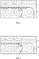
- FIG. 1 illustrates an exemplary self-clamping handrail device 100 in accordance with one or more embodiments.
- the handrail device 100 is shown as being in an initial or neutral position, which may be distinguished from an operation position as described further below.
- the handrail device 100 may include a main tooth wheel 1 mounted on a housing 5 that may be fixed in an escalator or moving walkway and driven by a main drive belt (not shown) via a pulley (not shown).
- the main tooth wheel 1 may drive a tooth belt 2.
- Overlaid on the tooth belt 2 may be a flat or tooth belt 3 that contacts, with a specific coated back, a handrail 4 on the surface that is exposed to and potentially engaged by passengers riding the escalator and drives the handrail 4 in an intended direction.
- the tooth belt 2, the belt 3, and the handrail 4 may form a belt-handrail compound 2-4 and travel between a clamping frame 7 and a counter bar 6.
- the clamping frame 7 and the counter bar 6 may include mounted rollers to provide support for the belt-handrail compound 2-4.
- the counter bar 6 In an initial or minimal tension force position, the counter bar 6 may be pressed by one or more springs 8 towards the handrail 4 and this pressure may be transmitted to the clamping frame 7.
- the counter bar 6 may be horizontally (longitudinally) coupled with the clamping frame 7.
- the counter bar 6 may include one or more (e.g., two) vertically oriented bed stops that may be mounted on the housing 5. The bed stops may be configured to limit the extent of vertical movement of the counter bar 6.
- the counter bar 6 does not touch one of the bed stops and might only be pressed by a relatively low initial spring force (associated with the spring(s) 8) towards the belt-handrail compound 2-4.
- the force provided by the spring(s) 8 may be selected to be strong enough to provide an initial movement of the clamping frame 7 along a clamping curve 10.
- the force may be a function of friction relations between the belt 3 and the handrail 4 and may serve as a "minimum force".
- the clamping frame 7 may carry or include some or all of the rollers 12 and 13 for the tooth belt 2 and the belt 3, respectively.
- the clamping frame 7 may be configured to be moved or displaced in a horizontal and/or vertical direction. Movement of the clamping frame 7 may be determined by movement of a roller 9 within the clamping curve 10.
- the roller 9 may correspond to a bearing surface, a low friction surface, a slider element, etc.
- the clamping roller 9 may be fixed on the clamping frame 7.
- the clamping curve 10, which may correspond to a slot in the housing 5, may be designed or fabricated such that the tooth belt 2 has in every position of the clamping frame 7 the same length.
- any curves or movement of the frame 7 may be such that at all points of motion the tension in the belt 2 may be constant (e.g., no stretch).
- a clamping curve 10 may be used that is not that strong (e.g., steeper wedge) and when the belt 2 is loosening a little bit, this loosening may be neglected or an idler roller may be implemented.
- the handrail device 100 is shown in operation with moving directions (indicated via the arrows shown) of the tooth wheel 1, the tooth belt 2, the belt 3, and the handrail 4. Also shown in FIG. 2 are the resulting forces (normal N and tension F) on the handrail 4. Due to tension force F, the clamping frame 7 has moved in the direction of the tension force F (e.g., to the right in FIG. 2 ) relative to the initial or neutral position shown in FIG. 1 . The movement of the clamping frame 7 may follow the clamping curve 10 based on a movement or a rolling of the clamping roller 9. The counter bar 6 may move or travel the same horizontal distance as the clamping frame 7.
- the (resultant) forces may be directly loaded to the housing 5 and not the spring 8.
- the counter bar 6 might not move anymore in a vertical direction.
- the clamping frame 7 may have moved, the tooth belt 2 may have the same length in this changed position.
- the belt 3 length might not have changed, as the belt 3 system may have moved together with the clamping frame 7.
- the counter bar 6 may be adjusted with spring forces.
- the counter bar 6 may touch the hard bed stops when a passenger load is applied on the handrail 4.
- the counter bar 6 may return to the initial spring force load position when the handrail is released again.
- the clamping frame 7 may move or travel in the direction of the tension force F (which would be to the right in FIG. 2 ) along the clamping curve 10.
- the pressure on the handrail 4 may increase (potentially at one or more multiples of the increase in tension force F) as a function of a current tangential angle in a contact point between the clamping roller 9 and the clamping curve 10.
- a higher normal force N may be realized, which may allow for a higher tension force F to be applied on the handrail 4.
- the shape of the clamping curve 10 may act like a wedge, such that a given tension force F on the handrail 4 may result in a multiple higher normal force N on it.
- the normal force N may increase in relation to the tension force F.
- the increase in the normal force N may be eight to ten times greater than the tension force F.
- a coefficient of friction between the belt 3 and the handrail 4 is greater than the reciprocal value of this multiple (e.g., greater than 1/8 - 1/10), no sliding may occur, which may be used to realize a self-clamping effect.
- the coefficient of friction between the belt 3 and the handrail 4 may be much larger than "normal" steel coefficients of friction, e.g., approximately a number between one and three.
- the relative flat angle (wedge angle) at the contact point between the clamping roller 9 and the clamping curve 10 may assure a sufficient grip to drive the handrail 4 without slipping or stopping.
- the pressure of the handrail 4 material and the spring 8 force may make the clamping roller 9 move or travel towards the lowest point or the bottom of the clamping curve 10 until a balance of forces is again established.
- This rebounding may guarantee that an adequate normal force N, related to the tension force F, is applied on the handrail 4.
- the ability to vary the normal force N based upon load provides the benefit that the normal force N is not required to be maintained at a constant high level corresponding to the maximum normal force needed for a fully loaded escalator, as is the case in conventional linear handrail drives. As a result, there is less pressure on the handrail, reduced wear and this feature permits the outer surface of the handrail to be used as the driving surface.
- the tension force F is shown as being directed to the right. If the tension force F changes direction (e.g., the tension force F is directed to the left), the same mechanical principles may apply, such that, e.g., the clamping frame 7 may move to the left via the clamping curve 10.
- FIG. 3 illustrates a pairing of the tooth belt 2 and the belt 3 in accordance with one or more embodiments.
- the belt 3 is shown as including teeth that may mate with, or engage, teeth of the tooth belt 2.
- Combining two belts may increase the moment of inertia of a belt system (e.g., the belt compound formed by belts 2 and 3) when supporting the handrail 4 under the normal force N. This may make the belt system stiffer and therefore a bending or deflection between support rollers may be less and a contact surface on the handrail 4 of the pressing rollers may be wider leading to a bigger contact zone with lower pressure. Stated in a slightly different way, use of a stiffer belt may serve to spread force over a greater contact area, thereby lowering pressure imposed on the belt.
- a stiffer belt may serve to spread force over a greater contact area, thereby lowering pressure imposed on the belt.
- Tooth belt 2 may drive the (loose) belt 3.
- Belt 3 may serve to stiffen the belt system in the pressure zone.
- the backside (e.g., the non-tooth side) of the belt 3 that contacts the handrail 4 may be coated with one or more materials (e.g., neoprene).
- the coating materials may be selected such that a coefficient of friction between the belt 3 and the handrail 4 is relatively large, yet on the other hand the coating may be relatively soft such that a pressure area on the handrail 4 is widened and therefore the grip on the handrail 4 may be smooth, such that marks or damage to the passenger side of the handrail 4 may be avoided.
- FIG. 4 illustrates a pairing of the tooth belt 2 and the belt 3 in accordance with one or more embodiments.
- the belt 3 is (substantially) flat and does not include the teeth shown in FIG. 3 .
- one or both of belts 2 and 3 may be implemented as a Poly-V belt.
- the belt 3 might not be included.
- the teeth of the tooth belt 2 may (directly) touch the inner surface of the handrail 4; however, it should be noted that this arrangement may increase the risk of deformation of the handrail 4.
- multiple belts may be combined.
- three or more belts may be combined with each other to increase the stiffness of the belt-handrail compound under a pressure zone.
- one or more rollers may be placed between the counter bar 6 and the housing 5 to reduce friction forces between the longitudinally moving counter bar 6 and the housing 5. Such an arrangement may serve as a bed stop.
- a lever system may be implemented to facilitate the movement provided by the clamping frame 7 described above. Such a lever system may be used in addition to, or as an alternative to, the curve 10. The length of the belt 2 may remain unchanged during movements.
- the clamping frame 7 may move along a curve where a length of the belt 2 is changing.
- a tension associated with the belt 2 may be established or maintained through use of one or more tension pulleys.
- a belt may be placed on the rollers of the counter bar 6 to provide for better impact on the back side of the handrail 4.
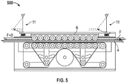
- an asymmetrical system 500 in accordance with one or more embodiments is shown.
- the system 500 may clamp and transmit the tension force F to the handrail 4.
- the system 500 may be in a released state or condition; for example, the counter bar 6 may be released by a release mechanism 11 such that no tension force F is applied on the handrail 4.
- the system 500 may provide a benefit of allowing a tension force F to be selectively applied in a particular direction.
- a handrail length compensation device may be used between the two asymmetric drives because between them the handrail tension force may approximately be close to zero.
- FIG. 6 illustrates an exemplary schematic of a handrail system 600 with asymmetrical systems in accordance with one or more embodiments.
- the system 600 includes a left side force clamping system 21 and a right side force clamping system 22.
- the systems 21 and 22 may correspond to, or be analogous to, the system 500 of FIG. 5 .
- the systems 21 and 22 may be applied to a common handrail 4.
- a handrail length compensation device 23 may be placed between the systems 21 and 22.
- the systems 21 and 22 may be used to guarantee that regardless in which direction the moving walkway/escalator is running, the part of the handrail 4 that is length compensated in the handrail length compensation device 23 is always tension force free, so that a relatively simple handrail compensation device can be used and the moving walkway/escalator is fully operable in both directions.
- FIG. 7 a flow chart of an exemplary method is shown in accordance with one or more embodiments.
- the method of FIG. 7 may be used to provide for a self-clamping handrail as described herein.
- the method of FIG. 7 may be executed by one or more systems or devices, such as those described herein.
- a determination may be made regarding an amount of tension force (F) that is applied to a handrail.
- the applied tension force may be a function of a load associated with the handrail. For example, the applied tension force may be based on whether passengers are using the handrail.
- a normal force may be provided to the handrail.
- the provided normal force may be based at least in part on the applied tension force of block 702.
- the provided normal force may be based on one or more springs if, e.g., the applied tension force is less than a threshold level or value.
- the normal force may be a multiple of the tension force.
- whether a normal force (N) should be applied may be based on, or a function, of use. For example, if a passenger conveyor is shut down or not in use, normal force (N) may be removed from the handrail, thereby reducing the risk of deforming the outer surface of the handrail.
- a clamping frame may move along a clamping curve in a direction of the tension force when the tension force increases relative to an initial value.
- the clamping frame may move through an arc if either a slotted curve or links are used.
- a clamping frame may move through an arc or clamping curve in a direction of the tension force, e.g., when the tension force increases relative to an initial value.
- FIG. 7 is illustrative. In some embodiments, one or more of the blocks or operations (or portions thereof) may be optional. In some embodiments, the operations may execute in an order or sequence different from what is shown. In some embodiments, one or more additional operations not shown may be included.
- normal forces may be reduced.
- normal forces may be selected based on tension forces, one or both of which may be a function of load.
- a passenger conveyor e.g., an escalator or moving walk
- frictional forces e.g., balustrade, newel, return
- normal forces may be reduced to a minimum level needed to ensure initial movement of the clamping frame. If the handrail is loaded as a result of passenger use, the normal forces may be increased adequately to avoid a slipping of the handrail. In this respect, a self-clamping handrail drive may be provided.
- Operational life of the handrail may be increased due to of the ability to vary the applied forces (e.g., normal forces) on the handrail. Normal forces may be even further reduced or de-concentrated due to one or more of: (1) the use of a tooth belt between driving wheels and the handrail, (2) a stiffening of one or more belts or belt compounds (e.g., tooth belt contact with handrail), and (3) frictional pairing between an adhesive passenger side of the handrail and the relatively adhesive belt coating.
- Normal forces may be even further reduced or de-concentrated due to one or more of: (1) the use of a tooth belt between driving wheels and the handrail, (2) a stiffening of one or more belts or belt compounds (e.g., tooth belt contact with handrail), and (3) frictional pairing between an adhesive passenger side of the handrail and the relatively adhesive belt coating.
- the self-clamping systems described herein may adapt to different handrail thicknesses.
- the counter part of the driving belt system may automatically adjust, e.g., via spring or a self-locking, to the thinner handrail.
- Distance may be accounted for or adjusted in order to provide a relatively low initial (starting) normal force.
- a self-clamping handrail drive may be driven directly with the same tooth (one side tooth) belt that is used for the main drive, which may help to minimize the required space.
- various functions or acts may take place at a given location and/or in connection with the operation of one or more apparatuses, systems, or devices. For example, in some embodiments, a portion of a given function or act may be performed at a first device or location, and the remainder of the function or act may be performed at one or more additional devices or locations.
- an apparatus or system may include one or more processors, and memory storing instructions that, when executed by the one or more processors, cause the apparatus or system to perform one or more methodological acts as described herein.
- one or more input/output (I/O) interfaces may be coupled to one or more processors and may be used to provide a user with an interface to an escalator or walkway system.
- I/O input/output
- Various mechanical components known to those of skill in the art may be used in some embodiments.
- Embodiments may be implemented as one or more apparatuses, systems, and/or methods.
- instructions may be stored on one or more computer-readable media, such as a transitory and/or non-transitory computer-readable medium.
- the instructions when executed, may cause an entity (e.g., an apparatus or system) to perform one or more methodological acts as described herein.
Landscapes
- Escalators And Moving Walkways (AREA)
Claims (15)
- Dispositif de main courante à auto-serrage (100) comprenant :un composé courroie-main courante (2-4) comprenant une courroie (2 ; 3), et une main courante couplée à la courroie (2 ; 3) ;une contre-barre (6) et un cadre de serrage (7) configurés pour supporter le composé courroie-main courante (2-4) lorsque le composé courroie-main courante (2-4) passe entre la contre-barre (6) et le cadre de serrage (7) ;caractérisé en ce quele cadre de serrage (7) est configuré pour se déplacer sur une courbe de serrage (10) sur la base d'une force de tension (F) appliquée à la main courante (4) ; etla courroie (2, 3) est configurée pour appliquer une force normale (N) à la main courante (4) sur la base au moins en partie de la force de tension (F).
- Dispositif de main courante (100) selon la revendication 1, dans lequel la courbe de serrage (10) est configurée de telle sorte que la courroie (2, 3) a dans chaque position du cadre de serrage (7) la même longueur.
- Dispositif de main courante (100) selon la revendication 1 ou 2, comprenant en outre :
un ou plusieurs ressorts (8) configurés pour fournir une force de ressort qui fournit une force normale (N) suffisante pour bloquer le composé courroie-main courante (2-4) ensemble via un frottement. - Dispositif de main courante (100) selon l'une quelconque des revendications 1 à 3, comprenant en outre :
un rouleau de courbe de serrage (9) monté sur le cadre de serrage (7) et configuré pour se déplacer le long de la courbe de serrage (10) ; et/ou un mécanisme de liaison conçu pour que le cadre de serrage (7) se déplace autour de la courbe de serrage (10). - Dispositif de main courante (100) selon l'une quelconque des revendications 1 à 4, dans lequel le composé courroie-main courante (2-4) comporte une première courroie (3) et une seconde courroie (2) couplée à la première courroie (3) ; la main courante (4) étant couplée à la première courroie (3), la première courroie (3) et la seconde courroie (2) appliquant la force normale (N) à la main courante (4) sur la base au moins en partie de la force de tension (F).
- Dispositif de main courante (100) selon la revendication 5, dans lequel la seconde courroie (2) comprend des dents qui se mettent en prise avec la première courroie (3) dans une zone de pression où la force normale (N) est appliquée à la main courante (4) ;
dans lequel en particulier la première courroie (3) comprend des dents qui se mettent en prise avec les dents de la seconde courroie (2) ; ou
dans lequel la première courroie (3) est une courroie plate. - Dispositif de main courante (100) selon l'une quelconque des revendications 1 à 6, dans lequel le dispositif de main courante (100) est un dispositif asymétrique configuré pour serrer dans une première direction et relâcher dans une seconde direction.
- Dispositif de main courante (100) selon la revendication 7, dans lequel le dispositif de main courante (100) est couplé à un second dispositif de main courante asymétrique (100), et dans lequel le second dispositif de main courante asymétrique (100) est configuré pour serrer la main courante (4) dans la seconde direction et relâcher dans la première direction, et dans lequel le dispositif asymétrique (100) est couplé au second dispositif de main courante asymétrique (100) via un dispositif de compensation de longueur de main courante (23).
- Dispositif de main courante (100) selon l'une quelconque des revendications 1 à 8, dans lequel le dispositif de main courante (100) est mis en oeuvre en tant que partie d'au moins l'un d'une passerelle et d'un escalator.
- Procédé de fourniture d'un dispositif d'entraînement de main courante à auto-serrage (4) utilisant le dispositif de main courante à auto-serrage selon l'une quelconque des revendications précédentes, comprenant :
la fourniture (704) de la force normale variable (N) à la main courante (4) basée au moins en partie sur la force de tension (F) dans la main courante (4). - Procédé selon la revendication 10, comprenant en outre :la variation de la force normale (N) en déplaçant le cadre de serrage (7) le long de la courbe de serrage (10) dans la direction de la force de tension (F) lorsque la force de tension (F) augmente par rapport à la valeur initiale ;dans lequel en particulier la force normale (N) augmente en relation directe avec la force de tension (F) ;dans lequel en particulier un coefficient de frottement entre la courroie (2 ; 3) couplée à la main courante et la main courante (4) est supérieur à un rapport de la force de tension (F) sur la force normale (N) afin d'assurer l'auto-serrage.
- Procédé selon la revendication 10 ou 11, comprenant en outre :le couplage de la courroie (2 ; 3) à la main courante (4) ; etdans lequel la courroie (2 ; 3) comporte un revêtement sélectionné pour fournir un coefficient de frottement particulier entre la courroie (3) et la main courante (4).
- Procédé selon l'une quelconque des revendications 10 à 12, comprenant en outre :le couplage de la première courroie (3) à la main courante (4) ; etle couplage de la seconde courroie (2) à la première courroie (3),dans lequel la seconde courroie (2) comprend des dents qui se mettent en prise avec la première courroie (3) dans la zone de pression où la force normale (N) est appliquée à la main courante (4) ;dans lequel en particulier la première courroie (3) comprend des dents qui se mettent en prise avec les dents (3) de la seconde courroie.
- Procédé selon l'une quelconque des revendications 10 à 13, comprenant en outre :
l'application d'une force d'entraînement sur une surface externe de la main courante (4), dans lequel la surface externe est configurée pour être en contact avec un passager. - Procédé selon l'une quelconque des revendications 10 à 14, comprenant en outre :l'application d'une force normale minimale suffisante pour entraîner la main courante (4) à des charges de fonctionnement minimales ;dans lequel en particulier la force normale (N) comprime un ressort (8) jusqu'à ce qu'une contre-barre (6) touche une butée de lit supérieure sur un logement (5) et la contre-barre (6) ne puisse plus se déplacer dans une direction verticale.
Applications Claiming Priority (1)
| Application Number | Priority Date | Filing Date | Title |
|---|---|---|---|
| PCT/US2013/031439 WO2014142891A1 (fr) | 2013-03-14 | 2013-03-14 | Dispositif d'entraînement de main-courante à auto-serrage |
Publications (3)
| Publication Number | Publication Date |
|---|---|
| EP2969879A1 EP2969879A1 (fr) | 2016-01-20 |
| EP2969879A4 EP2969879A4 (fr) | 2016-11-16 |
| EP2969879B1 true EP2969879B1 (fr) | 2018-10-24 |
Family
ID=51537281
Family Applications (1)
| Application Number | Title | Priority Date | Filing Date |
|---|---|---|---|
| EP13877802.2A Not-in-force EP2969879B1 (fr) | 2013-03-14 | 2013-03-14 | Dispositif d'entraînement de main-courante à auto-serrage |
Country Status (4)
| Country | Link |
|---|---|
| US (1) | US9556005B2 (fr) |
| EP (1) | EP2969879B1 (fr) |
| CN (1) | CN105228939B (fr) |
| WO (1) | WO2014142891A1 (fr) |
Families Citing this family (5)
| Publication number | Priority date | Publication date | Assignee | Title |
|---|---|---|---|---|
| AT517610B1 (de) * | 2015-09-17 | 2017-03-15 | Innova Patent Gmbh | Vorrichtung zum Antreiben eines Handlaufes |
| JP6715177B2 (ja) * | 2016-12-12 | 2020-07-01 | 矢崎総業株式会社 | ワイヤハーネス |
| WO2019029992A1 (fr) * | 2017-08-10 | 2019-02-14 | Inventio Ag | Système d'entraînement de main-courante comprenant des éléments d'entraînement intégrés dans la main-courante |
| CN110921478B (zh) * | 2018-09-19 | 2023-08-04 | 奥的斯电梯公司 | 扶手带自动张紧系统和调节扶手带的张紧程度的方法 |
| CN118062705A (zh) * | 2022-11-22 | 2024-05-24 | 奥的斯电梯公司 | 自动传送装置 |
Family Cites Families (22)
| Publication number | Priority date | Publication date | Assignee | Title |
|---|---|---|---|---|
| GB1304821A (fr) | 1970-01-16 | 1973-01-31 | ||
| US4535880A (en) * | 1983-09-15 | 1985-08-20 | Westinghouse Electric Corp. | Escalator |
| US4998613A (en) * | 1989-02-28 | 1991-03-12 | Otis Elevator Company | Self adjustable escalator handrail drive |
| US5133443A (en) * | 1991-03-15 | 1992-07-28 | Otis Elevator Company | Self adjustable escalator handrail drive with balanced drive chain tension |
| US5117960A (en) * | 1991-08-15 | 1992-06-02 | Otis Elevator Company | Linear belt handrail drive |
| US5125494A (en) * | 1991-09-03 | 1992-06-30 | Montgomery Elevator Company | Handrail drive mechanism for a passenger conveyor |
| US5645156A (en) | 1993-09-01 | 1997-07-08 | Otis Elevator Company | Device for monitoring escalator handrail speed |
| US5366060A (en) | 1993-10-07 | 1994-11-22 | Johnson Gerald E | Balustrade handrail entry housing |
| US5372232A (en) | 1994-03-23 | 1994-12-13 | Otis Elevator Company | Handrail drive pressure chain with soft rollers |
| US5881859A (en) | 1996-10-10 | 1999-03-16 | Bianchi; James N. | Escalator handrail drive mechanism |
| US6530468B2 (en) * | 2000-09-21 | 2003-03-11 | Crisplant A/S | Conveyor having a chain drive mechanism |
| US6450317B1 (en) * | 2000-09-26 | 2002-09-17 | Otis Elevator Company | Escalator drive machine |
| CN100369799C (zh) | 2002-02-06 | 2008-02-20 | 塞姆普雷特控股股份公司 | 自动扶梯或自动升梯和扶手以及扶手导向装置和驱动装置 |
| US8016097B2 (en) * | 2003-02-06 | 2011-09-13 | Otis Elevator Company | Escalator linear belt handrail drive |
| JP4115304B2 (ja) * | 2003-03-07 | 2008-07-09 | 東芝エレベータ株式会社 | 乗客コンベア |
| JP4938966B2 (ja) * | 2003-04-04 | 2012-05-23 | インベンテイオ・アクテイエンゲゼルシヤフト | エスカレータまたは動く歩道のための手摺り駆動装置 |
| JP4464737B2 (ja) * | 2004-04-27 | 2010-05-19 | 株式会社日立ビルシステム | 乗客コンベアの移動手摺駆動装置 |
| DE112006004175T5 (de) * | 2006-12-21 | 2009-10-15 | Otis Elevator Company, Farmington | Antriebsvorrichtung für den Handlauf einer Personenbeförderungsvorrichtung |
| ES2340563B1 (es) * | 2008-01-18 | 2011-04-13 | Thyssenkrupp Elevator Innovation Center, S.A. | Sistema rotativo de accionamiento lineal de pasamanos para escaleras mecanicas y pasillos rodantes. |
| US8061215B2 (en) | 2008-06-13 | 2011-11-22 | Ehc Canada, Inc. | Apparatus for and method of measuring tension in a handrail for an escalator or moving walkway |
| CN101423169A (zh) * | 2008-10-30 | 2009-05-06 | 苏州市申龙电梯有限公司 | 扶手摩擦带的驱动与导向装置 |
| WO2011088895A1 (fr) * | 2010-01-20 | 2011-07-28 | Kone Corporation | Dispositif de transport de passagers |
-
2013
- 2013-03-14 CN CN201380076613.7A patent/CN105228939B/zh not_active Expired - Fee Related
- 2013-03-14 EP EP13877802.2A patent/EP2969879B1/fr not_active Not-in-force
- 2013-03-14 WO PCT/US2013/031439 patent/WO2014142891A1/fr not_active Ceased
- 2013-03-14 US US14/773,931 patent/US9556005B2/en not_active Expired - Fee Related
Also Published As
| Publication number | Publication date |
|---|---|
| EP2969879A1 (fr) | 2016-01-20 |
| WO2014142891A1 (fr) | 2014-09-18 |
| US9556005B2 (en) | 2017-01-31 |
| EP2969879A4 (fr) | 2016-11-16 |
| US20160016760A1 (en) | 2016-01-21 |
| CN105228939B (zh) | 2019-01-15 |
| CN105228939A (zh) | 2016-01-06 |
Similar Documents
| Publication | Publication Date | Title |
|---|---|---|
| US9556005B2 (en) | Self-clamping handrail drive | |
| RU2441831C2 (ru) | Подъемник с тормозным устройством и способ торможения в подъемнике | |
| US5307920A (en) | Moving handrail drive | |
| US5881859A (en) | Escalator handrail drive mechanism | |
| TW200531915A (en) | Conveyer device | |
| US5427221A (en) | Escalator handrail drive system | |
| JP5612140B2 (ja) | 乗客コンベア | |
| CN104854014B (zh) | 用于驱动自动扶梯或自动步道的扶手的装置 | |
| CN105764832B (zh) | 用于自动扶梯或移动步道的扶手驱动设备 | |
| CN104271488A (zh) | 用于乘客输送机的制动系统 | |
| KR101012184B1 (ko) | 에스컬레이터 선형 벨트 핸드레일 구동부 | |
| JPS61193962A (ja) | コンベヤ装置 | |
| US2973084A (en) | Reversible drive for moving sidewalks and the like | |
| CN108163689B (zh) | 扶手摩擦检测装置 | |
| JP6453423B1 (ja) | 乗客コンベア用手摺ベルト及びそれを用いた乗客コンベア | |
| US5259492A (en) | Dual belt linear handrail drive | |
| JP2013063852A (ja) | 双方向型の動く歩道 | |
| JP5645461B2 (ja) | 乗客コンベヤ | |
| CN205294585U (zh) | 乘客输送机的扶手带驱动装置 | |
| JP5137882B2 (ja) | 乗客コンベアの移動手摺駆動装置 | |
| WO2011113487A1 (fr) | Trottoir roulant | |
| JPH0117581Y2 (fr) | ||
| JP2006168951A (ja) | 乗客コンベヤーの移動手摺駆動装置 | |
| JPS6131028Y2 (fr) | ||
| JP4946312B2 (ja) | エレベータ駆動装置 |
Legal Events
| Date | Code | Title | Description |
|---|---|---|---|
| PUAI | Public reference made under article 153(3) epc to a published international application that has entered the european phase |
Free format text: ORIGINAL CODE: 0009012 |
|
| 17P | Request for examination filed |
Effective date: 20151013 |
|
| AK | Designated contracting states |
Kind code of ref document: A1 Designated state(s): AL AT BE BG CH CY CZ DE DK EE ES FI FR GB GR HR HU IE IS IT LI LT LU LV MC MK MT NL NO PL PT RO RS SE SI SK SM TR |
|
| AX | Request for extension of the european patent |
Extension state: BA ME |
|
| RIN1 | Information on inventor provided before grant (corrected) |
Inventor name: STUMMER, RAINER Inventor name: TUREK, ALEXANDER Inventor name: SRB-GAFFRON, WALTER |
|
| DAX | Request for extension of the european patent (deleted) | ||
| A4 | Supplementary search report drawn up and despatched |
Effective date: 20161018 |
|
| RIC1 | Information provided on ipc code assigned before grant |
Ipc: B66B 23/02 20060101AFI20161012BHEP Ipc: B66B 23/04 20060101ALI20161012BHEP |
|
| RAP1 | Party data changed (applicant data changed or rights of an application transferred) |
Owner name: OTIS ELEVATOR COMPANY |
|
| GRAP | Despatch of communication of intention to grant a patent |
Free format text: ORIGINAL CODE: EPIDOSNIGR1 |
|
| STAA | Information on the status of an ep patent application or granted ep patent |
Free format text: STATUS: GRANT OF PATENT IS INTENDED |
|
| INTG | Intention to grant announced |
Effective date: 20180514 |
|
| GRAS | Grant fee paid |
Free format text: ORIGINAL CODE: EPIDOSNIGR3 |
|
| GRAA | (expected) grant |
Free format text: ORIGINAL CODE: 0009210 |
|
| STAA | Information on the status of an ep patent application or granted ep patent |
Free format text: STATUS: THE PATENT HAS BEEN GRANTED |
|
| AK | Designated contracting states |
Kind code of ref document: B1 Designated state(s): AL AT BE BG CH CY CZ DE DK EE ES FI FR GB GR HR HU IE IS IT LI LT LU LV MC MK MT NL NO PL PT RO RS SE SI SK SM TR |
|
| REG | Reference to a national code |
Ref country code: CH Ref legal event code: EP |
|
| REG | Reference to a national code |
Ref country code: IE Ref legal event code: FG4D |
|
| REG | Reference to a national code |
Ref country code: AT Ref legal event code: REF Ref document number: 1056431 Country of ref document: AT Kind code of ref document: T Effective date: 20181115 |
|
| REG | Reference to a national code |
Ref country code: DE Ref legal event code: R096 Ref document number: 602013045757 Country of ref document: DE |
|
| REG | Reference to a national code |
Ref country code: NL Ref legal event code: MP Effective date: 20181024 |
|
| REG | Reference to a national code |
Ref country code: LT Ref legal event code: MG4D |
|
| REG | Reference to a national code |
Ref country code: AT Ref legal event code: MK05 Ref document number: 1056431 Country of ref document: AT Kind code of ref document: T Effective date: 20181024 |
|
| PG25 | Lapsed in a contracting state [announced via postgrant information from national office to epo] |
Ref country code: NL Free format text: LAPSE BECAUSE OF FAILURE TO SUBMIT A TRANSLATION OF THE DESCRIPTION OR TO PAY THE FEE WITHIN THE PRESCRIBED TIME-LIMIT Effective date: 20181024 |
|
| PG25 | Lapsed in a contracting state [announced via postgrant information from national office to epo] |
Ref country code: NO Free format text: LAPSE BECAUSE OF FAILURE TO SUBMIT A TRANSLATION OF THE DESCRIPTION OR TO PAY THE FEE WITHIN THE PRESCRIBED TIME-LIMIT Effective date: 20190124 Ref country code: PL Free format text: LAPSE BECAUSE OF FAILURE TO SUBMIT A TRANSLATION OF THE DESCRIPTION OR TO PAY THE FEE WITHIN THE PRESCRIBED TIME-LIMIT Effective date: 20181024 Ref country code: BG Free format text: LAPSE BECAUSE OF FAILURE TO SUBMIT A TRANSLATION OF THE DESCRIPTION OR TO PAY THE FEE WITHIN THE PRESCRIBED TIME-LIMIT Effective date: 20190124 Ref country code: HR Free format text: LAPSE BECAUSE OF FAILURE TO SUBMIT A TRANSLATION OF THE DESCRIPTION OR TO PAY THE FEE WITHIN THE PRESCRIBED TIME-LIMIT Effective date: 20181024 Ref country code: IS Free format text: LAPSE BECAUSE OF FAILURE TO SUBMIT A TRANSLATION OF THE DESCRIPTION OR TO PAY THE FEE WITHIN THE PRESCRIBED TIME-LIMIT Effective date: 20190224 Ref country code: LT Free format text: LAPSE BECAUSE OF FAILURE TO SUBMIT A TRANSLATION OF THE DESCRIPTION OR TO PAY THE FEE WITHIN THE PRESCRIBED TIME-LIMIT Effective date: 20181024 Ref country code: ES Free format text: LAPSE BECAUSE OF FAILURE TO SUBMIT A TRANSLATION OF THE DESCRIPTION OR TO PAY THE FEE WITHIN THE PRESCRIBED TIME-LIMIT Effective date: 20181024 Ref country code: LV Free format text: LAPSE BECAUSE OF FAILURE TO SUBMIT A TRANSLATION OF THE DESCRIPTION OR TO PAY THE FEE WITHIN THE PRESCRIBED TIME-LIMIT Effective date: 20181024 Ref country code: AT Free format text: LAPSE BECAUSE OF FAILURE TO SUBMIT A TRANSLATION OF THE DESCRIPTION OR TO PAY THE FEE WITHIN THE PRESCRIBED TIME-LIMIT Effective date: 20181024 Ref country code: FI Free format text: LAPSE BECAUSE OF FAILURE TO SUBMIT A TRANSLATION OF THE DESCRIPTION OR TO PAY THE FEE WITHIN THE PRESCRIBED TIME-LIMIT Effective date: 20181024 |
|
| PG25 | Lapsed in a contracting state [announced via postgrant information from national office to epo] |
Ref country code: AL Free format text: LAPSE BECAUSE OF FAILURE TO SUBMIT A TRANSLATION OF THE DESCRIPTION OR TO PAY THE FEE WITHIN THE PRESCRIBED TIME-LIMIT Effective date: 20181024 Ref country code: RS Free format text: LAPSE BECAUSE OF FAILURE TO SUBMIT A TRANSLATION OF THE DESCRIPTION OR TO PAY THE FEE WITHIN THE PRESCRIBED TIME-LIMIT Effective date: 20181024 Ref country code: SE Free format text: LAPSE BECAUSE OF FAILURE TO SUBMIT A TRANSLATION OF THE DESCRIPTION OR TO PAY THE FEE WITHIN THE PRESCRIBED TIME-LIMIT Effective date: 20181024 Ref country code: GR Free format text: LAPSE BECAUSE OF FAILURE TO SUBMIT A TRANSLATION OF THE DESCRIPTION OR TO PAY THE FEE WITHIN THE PRESCRIBED TIME-LIMIT Effective date: 20190125 Ref country code: PT Free format text: LAPSE BECAUSE OF FAILURE TO SUBMIT A TRANSLATION OF THE DESCRIPTION OR TO PAY THE FEE WITHIN THE PRESCRIBED TIME-LIMIT Effective date: 20190224 |
|
| REG | Reference to a national code |
Ref country code: DE Ref legal event code: R097 Ref document number: 602013045757 Country of ref document: DE |
|
| PG25 | Lapsed in a contracting state [announced via postgrant information from national office to epo] |
Ref country code: DK Free format text: LAPSE BECAUSE OF FAILURE TO SUBMIT A TRANSLATION OF THE DESCRIPTION OR TO PAY THE FEE WITHIN THE PRESCRIBED TIME-LIMIT Effective date: 20181024 Ref country code: IT Free format text: LAPSE BECAUSE OF FAILURE TO SUBMIT A TRANSLATION OF THE DESCRIPTION OR TO PAY THE FEE WITHIN THE PRESCRIBED TIME-LIMIT Effective date: 20181024 Ref country code: CZ Free format text: LAPSE BECAUSE OF FAILURE TO SUBMIT A TRANSLATION OF THE DESCRIPTION OR TO PAY THE FEE WITHIN THE PRESCRIBED TIME-LIMIT Effective date: 20181024 |
|
| PG25 | Lapsed in a contracting state [announced via postgrant information from national office to epo] |
Ref country code: SM Free format text: LAPSE BECAUSE OF FAILURE TO SUBMIT A TRANSLATION OF THE DESCRIPTION OR TO PAY THE FEE WITHIN THE PRESCRIBED TIME-LIMIT Effective date: 20181024 Ref country code: SK Free format text: LAPSE BECAUSE OF FAILURE TO SUBMIT A TRANSLATION OF THE DESCRIPTION OR TO PAY THE FEE WITHIN THE PRESCRIBED TIME-LIMIT Effective date: 20181024 Ref country code: RO Free format text: LAPSE BECAUSE OF FAILURE TO SUBMIT A TRANSLATION OF THE DESCRIPTION OR TO PAY THE FEE WITHIN THE PRESCRIBED TIME-LIMIT Effective date: 20181024 Ref country code: EE Free format text: LAPSE BECAUSE OF FAILURE TO SUBMIT A TRANSLATION OF THE DESCRIPTION OR TO PAY THE FEE WITHIN THE PRESCRIBED TIME-LIMIT Effective date: 20181024 |
|
| PLBE | No opposition filed within time limit |
Free format text: ORIGINAL CODE: 0009261 |
|
| STAA | Information on the status of an ep patent application or granted ep patent |
Free format text: STATUS: NO OPPOSITION FILED WITHIN TIME LIMIT |
|
| 26N | No opposition filed |
Effective date: 20190725 |
|
| PG25 | Lapsed in a contracting state [announced via postgrant information from national office to epo] |
Ref country code: SI Free format text: LAPSE BECAUSE OF FAILURE TO SUBMIT A TRANSLATION OF THE DESCRIPTION OR TO PAY THE FEE WITHIN THE PRESCRIBED TIME-LIMIT Effective date: 20181024 Ref country code: MC Free format text: LAPSE BECAUSE OF FAILURE TO SUBMIT A TRANSLATION OF THE DESCRIPTION OR TO PAY THE FEE WITHIN THE PRESCRIBED TIME-LIMIT Effective date: 20181024 |
|
| REG | Reference to a national code |
Ref country code: CH Ref legal event code: PL |
|
| GBPC | Gb: european patent ceased through non-payment of renewal fee |
Effective date: 20190314 |
|
| PG25 | Lapsed in a contracting state [announced via postgrant information from national office to epo] |
Ref country code: LU Free format text: LAPSE BECAUSE OF NON-PAYMENT OF DUE FEES Effective date: 20190314 |
|
| REG | Reference to a national code |
Ref country code: BE Ref legal event code: MM Effective date: 20190331 |
|
| PG25 | Lapsed in a contracting state [announced via postgrant information from national office to epo] |
Ref country code: IE Free format text: LAPSE BECAUSE OF NON-PAYMENT OF DUE FEES Effective date: 20190314 Ref country code: LI Free format text: LAPSE BECAUSE OF NON-PAYMENT OF DUE FEES Effective date: 20190331 Ref country code: CH Free format text: LAPSE BECAUSE OF NON-PAYMENT OF DUE FEES Effective date: 20190331 Ref country code: GB Free format text: LAPSE BECAUSE OF NON-PAYMENT OF DUE FEES Effective date: 20190314 |
|
| PG25 | Lapsed in a contracting state [announced via postgrant information from national office to epo] |
Ref country code: BE Free format text: LAPSE BECAUSE OF NON-PAYMENT OF DUE FEES Effective date: 20190331 |
|
| PG25 | Lapsed in a contracting state [announced via postgrant information from national office to epo] |
Ref country code: TR Free format text: LAPSE BECAUSE OF FAILURE TO SUBMIT A TRANSLATION OF THE DESCRIPTION OR TO PAY THE FEE WITHIN THE PRESCRIBED TIME-LIMIT Effective date: 20181024 |
|
| PGFP | Annual fee paid to national office [announced via postgrant information from national office to epo] |
Ref country code: DE Payment date: 20200218 Year of fee payment: 8 |
|
| PG25 | Lapsed in a contracting state [announced via postgrant information from national office to epo] |
Ref country code: MT Free format text: LAPSE BECAUSE OF NON-PAYMENT OF DUE FEES Effective date: 20190314 |
|
| PGFP | Annual fee paid to national office [announced via postgrant information from national office to epo] |
Ref country code: FR Payment date: 20200220 Year of fee payment: 8 |
|
| PG25 | Lapsed in a contracting state [announced via postgrant information from national office to epo] |
Ref country code: CY Free format text: LAPSE BECAUSE OF FAILURE TO SUBMIT A TRANSLATION OF THE DESCRIPTION OR TO PAY THE FEE WITHIN THE PRESCRIBED TIME-LIMIT Effective date: 20181024 |
|
| PG25 | Lapsed in a contracting state [announced via postgrant information from national office to epo] |
Ref country code: HU Free format text: LAPSE BECAUSE OF FAILURE TO SUBMIT A TRANSLATION OF THE DESCRIPTION OR TO PAY THE FEE WITHIN THE PRESCRIBED TIME-LIMIT; INVALID AB INITIO Effective date: 20130314 |
|
| REG | Reference to a national code |
Ref country code: DE Ref legal event code: R119 Ref document number: 602013045757 Country of ref document: DE |
|
| PG25 | Lapsed in a contracting state [announced via postgrant information from national office to epo] |
Ref country code: FR Free format text: LAPSE BECAUSE OF NON-PAYMENT OF DUE FEES Effective date: 20210331 Ref country code: DE Free format text: LAPSE BECAUSE OF NON-PAYMENT OF DUE FEES Effective date: 20211001 |
|
| PG25 | Lapsed in a contracting state [announced via postgrant information from national office to epo] |
Ref country code: MK Free format text: LAPSE BECAUSE OF FAILURE TO SUBMIT A TRANSLATION OF THE DESCRIPTION OR TO PAY THE FEE WITHIN THE PRESCRIBED TIME-LIMIT Effective date: 20181024 |