EP2970025B1 - Reparatur eines keramikmatrix-verbundwerkstoffes durch reaktive verarbeitung und mechanische verriegelung - Google Patents
Reparatur eines keramikmatrix-verbundwerkstoffes durch reaktive verarbeitung und mechanische verriegelung Download PDFInfo
- Publication number
- EP2970025B1 EP2970025B1 EP13821420.0A EP13821420A EP2970025B1 EP 2970025 B1 EP2970025 B1 EP 2970025B1 EP 13821420 A EP13821420 A EP 13821420A EP 2970025 B1 EP2970025 B1 EP 2970025B1
- Authority
- EP
- European Patent Office
- Prior art keywords
- constituent
- preform
- matrix composite
- ceramic matrix
- composite component
- Prior art date
- Legal status (The legal status is an assumption and is not a legal conclusion. Google has not performed a legal analysis and makes no representation as to the accuracy of the status listed.)
- Active
Links
Images


Classifications
-
- F—MECHANICAL ENGINEERING; LIGHTING; HEATING; WEAPONS; BLASTING
- F01—MACHINES OR ENGINES IN GENERAL; ENGINE PLANTS IN GENERAL; STEAM ENGINES
- F01D—NON-POSITIVE DISPLACEMENT MACHINES OR ENGINES, e.g. STEAM TURBINES
- F01D5/00—Blades; Blade-carrying members; Heating, heat-insulating, cooling or antivibration means on the blades or the members
- F01D5/005—Repairing methods or devices
-
- B—PERFORMING OPERATIONS; TRANSPORTING
- B28—WORKING CEMENT, CLAY, OR STONE
- B28B—SHAPING CLAY OR OTHER CERAMIC COMPOSITIONS; SHAPING SLAG; SHAPING MIXTURES CONTAINING CEMENTITIOUS MATERIAL, e.g. PLASTER
- B28B1/00—Producing shaped prefabricated articles from the material
- B28B1/30—Producing shaped prefabricated articles from the material by applying the material on to a core or other moulding surface to form a layer thereon
- B28B1/40—Producing shaped prefabricated articles from the material by applying the material on to a core or other moulding surface to form a layer thereon by wrapping, e.g. winding
- B28B1/42—Producing shaped prefabricated articles from the material by applying the material on to a core or other moulding surface to form a layer thereon by wrapping, e.g. winding using mixtures containing fibres, e.g. for making sheets by slitting the wound layer
-
- B—PERFORMING OPERATIONS; TRANSPORTING
- B28—WORKING CEMENT, CLAY, OR STONE
- B28B—SHAPING CLAY OR OTHER CERAMIC COMPOSITIONS; SHAPING SLAG; SHAPING MIXTURES CONTAINING CEMENTITIOUS MATERIAL, e.g. PLASTER
- B28B21/00—Methods or machines specially adapted for the production of tubular articles
- B28B21/42—Methods or machines specially adapted for the production of tubular articles by shaping on or against mandrels or like moulding surfaces
- B28B21/48—Methods or machines specially adapted for the production of tubular articles by shaping on or against mandrels or like moulding surfaces by wrapping, e.g. winding
-
- C—CHEMISTRY; METALLURGY
- C04—CEMENTS; CONCRETE; ARTIFICIAL STONE; CERAMICS; REFRACTORIES
- C04B—LIME, MAGNESIA; SLAG; CEMENTS; COMPOSITIONS THEREOF, e.g. MORTARS, CONCRETE OR LIKE BUILDING MATERIALS; ARTIFICIAL STONE; CERAMICS; REFRACTORIES; TREATMENT OF NATURAL STONE
- C04B35/00—Shaped ceramic products characterised by their composition; Ceramics compositions; Processing powders of inorganic compounds preparatory to the manufacturing of ceramic products
- C04B35/515—Shaped ceramic products characterised by their composition; Ceramics compositions; Processing powders of inorganic compounds preparatory to the manufacturing of ceramic products based on non-oxide ceramics
- C04B35/56—Shaped ceramic products characterised by their composition; Ceramics compositions; Processing powders of inorganic compounds preparatory to the manufacturing of ceramic products based on non-oxide ceramics based on carbides or oxycarbides
- C04B35/565—Shaped ceramic products characterised by their composition; Ceramics compositions; Processing powders of inorganic compounds preparatory to the manufacturing of ceramic products based on non-oxide ceramics based on carbides or oxycarbides based on silicon carbide
- C04B35/571—Shaped ceramic products characterised by their composition; Ceramics compositions; Processing powders of inorganic compounds preparatory to the manufacturing of ceramic products based on non-oxide ceramics based on carbides or oxycarbides based on silicon carbide obtained from Si-containing polymer precursors or organosilicon monomers
-
- C—CHEMISTRY; METALLURGY
- C04—CEMENTS; CONCRETE; ARTIFICIAL STONE; CERAMICS; REFRACTORIES
- C04B—LIME, MAGNESIA; SLAG; CEMENTS; COMPOSITIONS THEREOF, e.g. MORTARS, CONCRETE OR LIKE BUILDING MATERIALS; ARTIFICIAL STONE; CERAMICS; REFRACTORIES; TREATMENT OF NATURAL STONE
- C04B35/00—Shaped ceramic products characterised by their composition; Ceramics compositions; Processing powders of inorganic compounds preparatory to the manufacturing of ceramic products
- C04B35/515—Shaped ceramic products characterised by their composition; Ceramics compositions; Processing powders of inorganic compounds preparatory to the manufacturing of ceramic products based on non-oxide ceramics
- C04B35/56—Shaped ceramic products characterised by their composition; Ceramics compositions; Processing powders of inorganic compounds preparatory to the manufacturing of ceramic products based on non-oxide ceramics based on carbides or oxycarbides
- C04B35/565—Shaped ceramic products characterised by their composition; Ceramics compositions; Processing powders of inorganic compounds preparatory to the manufacturing of ceramic products based on non-oxide ceramics based on carbides or oxycarbides based on silicon carbide
- C04B35/573—Shaped ceramic products characterised by their composition; Ceramics compositions; Processing powders of inorganic compounds preparatory to the manufacturing of ceramic products based on non-oxide ceramics based on carbides or oxycarbides based on silicon carbide obtained by reaction sintering or recrystallisation
-
- C—CHEMISTRY; METALLURGY
- C04—CEMENTS; CONCRETE; ARTIFICIAL STONE; CERAMICS; REFRACTORIES
- C04B—LIME, MAGNESIA; SLAG; CEMENTS; COMPOSITIONS THEREOF, e.g. MORTARS, CONCRETE OR LIKE BUILDING MATERIALS; ARTIFICIAL STONE; CERAMICS; REFRACTORIES; TREATMENT OF NATURAL STONE
- C04B35/00—Shaped ceramic products characterised by their composition; Ceramics compositions; Processing powders of inorganic compounds preparatory to the manufacturing of ceramic products
- C04B35/71—Ceramic products containing macroscopic reinforcing agents
- C04B35/78—Ceramic products containing macroscopic reinforcing agents containing non-metallic materials
- C04B35/80—Fibres, filaments, whiskers, platelets, or the like
-
- C—CHEMISTRY; METALLURGY
- C04—CEMENTS; CONCRETE; ARTIFICIAL STONE; CERAMICS; REFRACTORIES
- C04B—LIME, MAGNESIA; SLAG; CEMENTS; COMPOSITIONS THEREOF, e.g. MORTARS, CONCRETE OR LIKE BUILDING MATERIALS; ARTIFICIAL STONE; CERAMICS; REFRACTORIES; TREATMENT OF NATURAL STONE
- C04B37/00—Joining burned ceramic articles with other burned ceramic articles or other articles by heating
- C04B37/02—Joining burned ceramic articles with other burned ceramic articles or other articles by heating with metallic articles
- C04B37/023—Joining burned ceramic articles with other burned ceramic articles or other articles by heating with metallic articles characterised by the interlayer used
-
- F—MECHANICAL ENGINEERING; LIGHTING; HEATING; WEAPONS; BLASTING
- F01—MACHINES OR ENGINES IN GENERAL; ENGINE PLANTS IN GENERAL; STEAM ENGINES
- F01D—NON-POSITIVE DISPLACEMENT MACHINES OR ENGINES, e.g. STEAM TURBINES
- F01D5/00—Blades; Blade-carrying members; Heating, heat-insulating, cooling or antivibration means on the blades or the members
- F01D5/12—Blades
- F01D5/28—Selecting particular materials; Particular measures relating thereto; Measures against erosion or corrosion
- F01D5/282—Selecting composite materials, e.g. blades with reinforcing filaments
-
- F—MECHANICAL ENGINEERING; LIGHTING; HEATING; WEAPONS; BLASTING
- F01—MACHINES OR ENGINES IN GENERAL; ENGINE PLANTS IN GENERAL; STEAM ENGINES
- F01D—NON-POSITIVE DISPLACEMENT MACHINES OR ENGINES, e.g. STEAM TURBINES
- F01D5/00—Blades; Blade-carrying members; Heating, heat-insulating, cooling or antivibration means on the blades or the members
- F01D5/12—Blades
- F01D5/28—Selecting particular materials; Particular measures relating thereto; Measures against erosion or corrosion
- F01D5/284—Selection of ceramic materials
-
- B—PERFORMING OPERATIONS; TRANSPORTING
- B22—CASTING; POWDER METALLURGY
- B22F—WORKING METALLIC POWDER; MANUFACTURE OF ARTICLES FROM METALLIC POWDER; MAKING METALLIC POWDER; APPARATUS OR DEVICES SPECIALLY ADAPTED FOR METALLIC POWDER
- B22F5/00—Manufacture of workpieces or articles from metallic powder characterised by the special shape of the product
- B22F5/10—Manufacture of workpieces or articles from metallic powder characterised by the special shape of the product of articles with cavities or holes, not otherwise provided for in the preceding subgroups
- B22F2005/103—Cavity made by removal of insert
-
- B—PERFORMING OPERATIONS; TRANSPORTING
- B22—CASTING; POWDER METALLURGY
- B22F—WORKING METALLIC POWDER; MANUFACTURE OF ARTICLES FROM METALLIC POWDER; MAKING METALLIC POWDER; APPARATUS OR DEVICES SPECIALLY ADAPTED FOR METALLIC POWDER
- B22F2999/00—Aspects linked to processes or compositions used in powder metallurgy
-
- C—CHEMISTRY; METALLURGY
- C04—CEMENTS; CONCRETE; ARTIFICIAL STONE; CERAMICS; REFRACTORIES
- C04B—LIME, MAGNESIA; SLAG; CEMENTS; COMPOSITIONS THEREOF, e.g. MORTARS, CONCRETE OR LIKE BUILDING MATERIALS; ARTIFICIAL STONE; CERAMICS; REFRACTORIES; TREATMENT OF NATURAL STONE
- C04B2235/00—Aspects relating to ceramic starting mixtures or sintered ceramic products
- C04B2235/02—Composition of constituents of the starting material or of secondary phases of the final product
- C04B2235/50—Constituents or additives of the starting mixture chosen for their shape or used because of their shape or their physical appearance
- C04B2235/52—Constituents or additives characterised by their shapes
- C04B2235/5208—Fibers
- C04B2235/5216—Inorganic
- C04B2235/524—Non-oxidic, e.g. borides, carbides, silicides or nitrides
- C04B2235/5244—Silicon carbide
-
- C—CHEMISTRY; METALLURGY
- C04—CEMENTS; CONCRETE; ARTIFICIAL STONE; CERAMICS; REFRACTORIES
- C04B—LIME, MAGNESIA; SLAG; CEMENTS; COMPOSITIONS THEREOF, e.g. MORTARS, CONCRETE OR LIKE BUILDING MATERIALS; ARTIFICIAL STONE; CERAMICS; REFRACTORIES; TREATMENT OF NATURAL STONE
- C04B2235/00—Aspects relating to ceramic starting mixtures or sintered ceramic products
- C04B2235/02—Composition of constituents of the starting material or of secondary phases of the final product
- C04B2235/50—Constituents or additives of the starting mixture chosen for their shape or used because of their shape or their physical appearance
- C04B2235/52—Constituents or additives characterised by their shapes
- C04B2235/5208—Fibers
- C04B2235/5216—Inorganic
- C04B2235/524—Non-oxidic, e.g. borides, carbides, silicides or nitrides
- C04B2235/5248—Carbon, e.g. graphite
-
- C—CHEMISTRY; METALLURGY
- C04—CEMENTS; CONCRETE; ARTIFICIAL STONE; CERAMICS; REFRACTORIES
- C04B—LIME, MAGNESIA; SLAG; CEMENTS; COMPOSITIONS THEREOF, e.g. MORTARS, CONCRETE OR LIKE BUILDING MATERIALS; ARTIFICIAL STONE; CERAMICS; REFRACTORIES; TREATMENT OF NATURAL STONE
- C04B2235/00—Aspects relating to ceramic starting mixtures or sintered ceramic products
- C04B2235/60—Aspects relating to the preparation, properties or mechanical treatment of green bodies or pre-forms
- C04B2235/602—Making the green bodies or pre-forms by moulding
- C04B2235/6028—Shaping around a core which is removed later
-
- C—CHEMISTRY; METALLURGY
- C04—CEMENTS; CONCRETE; ARTIFICIAL STONE; CERAMICS; REFRACTORIES
- C04B—LIME, MAGNESIA; SLAG; CEMENTS; COMPOSITIONS THEREOF, e.g. MORTARS, CONCRETE OR LIKE BUILDING MATERIALS; ARTIFICIAL STONE; CERAMICS; REFRACTORIES; TREATMENT OF NATURAL STONE
- C04B2235/00—Aspects relating to ceramic starting mixtures or sintered ceramic products
- C04B2235/60—Aspects relating to the preparation, properties or mechanical treatment of green bodies or pre-forms
- C04B2235/614—Gas infiltration of green bodies or pre-forms
-
- C—CHEMISTRY; METALLURGY
- C04—CEMENTS; CONCRETE; ARTIFICIAL STONE; CERAMICS; REFRACTORIES
- C04B—LIME, MAGNESIA; SLAG; CEMENTS; COMPOSITIONS THEREOF, e.g. MORTARS, CONCRETE OR LIKE BUILDING MATERIALS; ARTIFICIAL STONE; CERAMICS; REFRACTORIES; TREATMENT OF NATURAL STONE
- C04B2235/00—Aspects relating to ceramic starting mixtures or sintered ceramic products
- C04B2235/60—Aspects relating to the preparation, properties or mechanical treatment of green bodies or pre-forms
- C04B2235/616—Liquid infiltration of green bodies or pre-forms
-
- C—CHEMISTRY; METALLURGY
- C04—CEMENTS; CONCRETE; ARTIFICIAL STONE; CERAMICS; REFRACTORIES
- C04B—LIME, MAGNESIA; SLAG; CEMENTS; COMPOSITIONS THEREOF, e.g. MORTARS, CONCRETE OR LIKE BUILDING MATERIALS; ARTIFICIAL STONE; CERAMICS; REFRACTORIES; TREATMENT OF NATURAL STONE
- C04B2237/00—Aspects relating to ceramic laminates or to joining of ceramic articles with other articles by heating
- C04B2237/30—Composition of layers of ceramic laminates or of ceramic or metallic articles to be joined by heating, e.g. Si substrates
- C04B2237/32—Ceramic
- C04B2237/36—Non-oxidic
- C04B2237/363—Carbon
-
- C—CHEMISTRY; METALLURGY
- C04—CEMENTS; CONCRETE; ARTIFICIAL STONE; CERAMICS; REFRACTORIES
- C04B—LIME, MAGNESIA; SLAG; CEMENTS; COMPOSITIONS THEREOF, e.g. MORTARS, CONCRETE OR LIKE BUILDING MATERIALS; ARTIFICIAL STONE; CERAMICS; REFRACTORIES; TREATMENT OF NATURAL STONE
- C04B2237/00—Aspects relating to ceramic laminates or to joining of ceramic articles with other articles by heating
- C04B2237/30—Composition of layers of ceramic laminates or of ceramic or metallic articles to be joined by heating, e.g. Si substrates
- C04B2237/32—Ceramic
- C04B2237/38—Fiber or whisker reinforced
-
- C—CHEMISTRY; METALLURGY
- C04—CEMENTS; CONCRETE; ARTIFICIAL STONE; CERAMICS; REFRACTORIES
- C04B—LIME, MAGNESIA; SLAG; CEMENTS; COMPOSITIONS THEREOF, e.g. MORTARS, CONCRETE OR LIKE BUILDING MATERIALS; ARTIFICIAL STONE; CERAMICS; REFRACTORIES; TREATMENT OF NATURAL STONE
- C04B2237/00—Aspects relating to ceramic laminates or to joining of ceramic articles with other articles by heating
- C04B2237/30—Composition of layers of ceramic laminates or of ceramic or metallic articles to be joined by heating, e.g. Si substrates
- C04B2237/40—Metallic
- C04B2237/402—Aluminium
-
- C—CHEMISTRY; METALLURGY
- C04—CEMENTS; CONCRETE; ARTIFICIAL STONE; CERAMICS; REFRACTORIES
- C04B—LIME, MAGNESIA; SLAG; CEMENTS; COMPOSITIONS THEREOF, e.g. MORTARS, CONCRETE OR LIKE BUILDING MATERIALS; ARTIFICIAL STONE; CERAMICS; REFRACTORIES; TREATMENT OF NATURAL STONE
- C04B2237/00—Aspects relating to ceramic laminates or to joining of ceramic articles with other articles by heating
- C04B2237/30—Composition of layers of ceramic laminates or of ceramic or metallic articles to be joined by heating, e.g. Si substrates
- C04B2237/40—Metallic
- C04B2237/404—Manganese or rhenium
-
- C—CHEMISTRY; METALLURGY
- C04—CEMENTS; CONCRETE; ARTIFICIAL STONE; CERAMICS; REFRACTORIES
- C04B—LIME, MAGNESIA; SLAG; CEMENTS; COMPOSITIONS THEREOF, e.g. MORTARS, CONCRETE OR LIKE BUILDING MATERIALS; ARTIFICIAL STONE; CERAMICS; REFRACTORIES; TREATMENT OF NATURAL STONE
- C04B2237/00—Aspects relating to ceramic laminates or to joining of ceramic articles with other articles by heating
- C04B2237/30—Composition of layers of ceramic laminates or of ceramic or metallic articles to be joined by heating, e.g. Si substrates
- C04B2237/40—Metallic
- C04B2237/405—Iron metal group, e.g. Co or Ni
-
- F—MECHANICAL ENGINEERING; LIGHTING; HEATING; WEAPONS; BLASTING
- F05—INDEXING SCHEMES RELATING TO ENGINES OR PUMPS IN VARIOUS SUBCLASSES OF CLASSES F01-F04
- F05D—INDEXING SCHEME FOR ASPECTS RELATING TO NON-POSITIVE-DISPLACEMENT MACHINES OR ENGINES, GAS-TURBINES OR JET-PROPULSION PLANTS
- F05D2300/00—Materials; Properties thereof
- F05D2300/60—Properties or characteristics given to material by treatment or manufacturing
- F05D2300/603—Composites; e.g. fibre-reinforced
- F05D2300/6033—Ceramic matrix composites [CMC]
-
- Y—GENERAL TAGGING OF NEW TECHNOLOGICAL DEVELOPMENTS; GENERAL TAGGING OF CROSS-SECTIONAL TECHNOLOGIES SPANNING OVER SEVERAL SECTIONS OF THE IPC; TECHNICAL SUBJECTS COVERED BY FORMER USPC CROSS-REFERENCE ART COLLECTIONS [XRACs] AND DIGESTS
- Y02—TECHNOLOGIES OR APPLICATIONS FOR MITIGATION OR ADAPTATION AGAINST CLIMATE CHANGE
- Y02T—CLIMATE CHANGE MITIGATION TECHNOLOGIES RELATED TO TRANSPORTATION
- Y02T50/00—Aeronautics or air transport
- Y02T50/60—Efficient propulsion technologies, e.g. for aircraft
-
- Y—GENERAL TAGGING OF NEW TECHNOLOGICAL DEVELOPMENTS; GENERAL TAGGING OF CROSS-SECTIONAL TECHNOLOGIES SPANNING OVER SEVERAL SECTIONS OF THE IPC; TECHNICAL SUBJECTS COVERED BY FORMER USPC CROSS-REFERENCE ART COLLECTIONS [XRACs] AND DIGESTS
- Y10—TECHNICAL SUBJECTS COVERED BY FORMER USPC
- Y10T—TECHNICAL SUBJECTS COVERED BY FORMER US CLASSIFICATION
- Y10T156/00—Adhesive bonding and miscellaneous chemical manufacture
- Y10T156/10—Methods of surface bonding and/or assembly therefor
- Y10T156/1002—Methods of surface bonding and/or assembly therefor with permanent bending or reshaping or surface deformation of self sustaining lamina
- Y10T156/1028—Methods of surface bonding and/or assembly therefor with permanent bending or reshaping or surface deformation of self sustaining lamina by bending, drawing or stretch forming sheet to assume shape of configured lamina while in contact therewith
-
- Y—GENERAL TAGGING OF NEW TECHNOLOGICAL DEVELOPMENTS; GENERAL TAGGING OF CROSS-SECTIONAL TECHNOLOGIES SPANNING OVER SEVERAL SECTIONS OF THE IPC; TECHNICAL SUBJECTS COVERED BY FORMER USPC CROSS-REFERENCE ART COLLECTIONS [XRACs] AND DIGESTS
- Y10—TECHNICAL SUBJECTS COVERED BY FORMER USPC
- Y10T—TECHNICAL SUBJECTS COVERED BY FORMER US CLASSIFICATION
- Y10T428/00—Stock material or miscellaneous articles
- Y10T428/20—Patched hole or depression
Definitions
- the present invention generally relates to ceramic matrix composite repairs, and more particularly, but not exclusively, to repairs or modifications of ceramic matrix composite components in a gas turbine engine.
- US 2008/0190552 discloses a method of brazing together two parts wherein a pad is interposed between the two surfaces of the parts that are to be joined together, said pad being formed by a refractory fiber texture, and being at least in part in contact with a brazing composition, and heat treatment is performed to liquefy the brazing composition so as to cause the molten brazing composition to be distributed by capillarity over the entire brazing area between the two parts covered by the pad.
- US 5,942,064 discloses a process for permanently joining at least two structural components together to form a molded body, in which a carbon-containing paste is introduced between the structural components to be joined and heated to form a carbon skeleton. This skeleton is then infiltrated with silicon at a temperature above 1,410°C to form silicon carbide.
- a carbon fiber-reinforced component with a system of microcracks is used as one of the structural components.
- One of the structural components is aligned with the other structural component in such a way as to leave a joint gap.
- the paste is pyrolyzed at a temperature in the range of 800-1,200°C to form a system of microcracks which approximately corresponds or is analogous to that of the carbon fiber-reinforced structural components.
- the system of microcracks of the pyrolyzed paste is then infiltrated with liquid silicon at a temperature above the melting point of silicon, which is thus converted to silicon carbide.
- US 5,306,565 discloses a composite ceramic structure which does not fail catastrophically and thus is useful as a ceramic rolling contact bearing assembly is disclosed.
- the structure is a ceramic monolith bonded through an interlayer to a fiber-reinforced ceramic body.
- the structure is useful at elevated temperatures.
- RABIN ET AL "Joining of fiber-reinforced SiC composites by in situ reaction methods",MATERIALS SCIENCE AND ENGINEERING A: STRUCTURAL MATERIALS:PROPERTIES, MICROSTRUCTURE & PROCESSING, LAUSANNE, CH, vol. 130, no. 1, 20 November 1990 (1990-11-20), pages L1-L5 , discloses two SiC CMC objects that both are cut to a desired size, thereby removing from both a non-conforming region. Both CMC's are coated with a SiC layer. Subsequently a joining material is applied between the two coated CMC objects.
- the joining material is a mixture of Ti, C and Ni.
- DE10035111 discloses porous SiC/C CMC bodies that are ground to remove a part of the surface. These bodies are joined using a reactive first constituent carbon joining material. The reactive surface region is, after joining the two bodies, reacted in a equilibrium reaction with a second reactive constituent (Si) in order to create a bond.
- Si reactive constituent
- CMC ceramic matrix composite
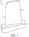
- a turbine blade 10 is an exemplary hot section component of a gas turbine engine.
- the blade 10 includes a leading edge 11, a trailing edge 12, and a root portion 13. While a turbine blade is shown in FIG. 1 , other hot section components are contemplated and can include combustion liners, turbine vanes, and seal segments, for example.
- a gas turbine engine hot section component such as blade 10 can be manufactured with at least a portion of the blade being a ceramic matrix composite material (CMC).
- Ceramic matrix composite parts can be formed by laying up and shaping a fiber reinforcing phase.
- the fiber reinforcing phase can include various materials such as metallic and ceramic materials.
- the fiber reinforcing phase is infiltrated with a ceramic matrix material.
- Various physical and chemical processes can be utilized to produce a CMC component with the lay up process and the infiltration process.
- CMC components are capable of forming various geometries including blades, vanes, and liners for example.
- CMC components can contain non-conformities due to complex macro and micro structures with multiple processing and handling functions applied during manufacturing.
- Non-conformities can exist due to operational damage including material degradation, foreign object impact, and wear to name a few.
- non-conformities can exist due to an engineering design change thereby necessitating modification of a CMC component.
- Non-conformities or defects can include, but are not limited to, delamination, cracks, porosity, mis-formed or partially formed components, and lost features. Manufacturing and material costs can prohibit an indiscriminate disposal policy of non-conforming CMC components.
- An embodiment of the present application includes a ceramic matrix composite repair which can include mechanical interlocking and reactive processing.
- the process of the present application includes the removal of at least a portion of a non-conformity, such as a flaw or an area out of specification, and the replacement of the removed portion with a new section of CMC.
- the new patch is integrated with the component by a bond structure formed during an equilibrium reaction and can include forms of Ti, Zr, Hf, Mo, TA, Yb, Y, carbides, borides, silicides, and intermetallics.
- One embodiment can include a repair process suitable for structural applications such as blades and vanes in a gas turbine engine.
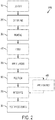
- FIG. 2 is a flow diagram illustrating the present application including a Process 1000 for repairing a CMC component.
- the Process 1000 includes an Operation 100 to identify a non-conformity or damaged area.
- Identification in Operation 100 can include several types of inspection techniques including, for example, visual, ultrasonic, magnetic-particle, liquid penetrant, radiographic, remote visual inspection (RVI), eddy-current testing, and low coherence interferometry, and digital imaging.
- a non-destructive evaluation such as IR inspection
- a non-conforming portion can be revealed which is accessible for repair or modification.
- An embodiment applied to manufacturing non-conformities can include in-line inspections.
- Another embodiment applied to operational non-conformities can include inspections following an end of life cycle or a perceived reduction in performance, for example.
- a section 1100 of a CMC component is shown.
- the geometry of the section 1100 of the component can vary in thickness, surface profile, size, topography and the like. The simplicity of the geometry shown is for clarity and should not be considered limiting.
- the section 1100 shown in FIG. 3a has a uniform cross-section. This property can also vary dependent on such parameters as material composition and component use.
- FIG. 3b shows a non-conforming portion 1200 within the section 1100 of the CMC component.
- the non-conforming portion 1200 can include a repairable portion identified on a component removed from service.
- the non-conforming portion 1200 can include deviating regions identified on a component during manufacturing when compared with inspection or design standards. Non-conformities can be dimensional or material related.
- the non-conforming portion 1200 can be identified using various non-destructive evaluation techniques such as, but not limited to, infrared inspection (IR), ultrasonic, magnetic-particle, liquid penetrant, radiographic, remote visual inspection (RVI), eddy-current testing, and low coherence interferometry, and x-ray computer tomography (x-ray CT).
- IR infrared inspection
- RVI remote visual inspection
- eddy-current testing eddy-current testing
- low coherence interferometry x-ray computer tomography
- an Operation 200 includes determining a non-conforming repair volume. Operation 200 can be in response to the non-conforming portion identified in Operation 100. In one embodiment, after an inspection tool reveals an area accessible for repair, a non-conforming region or repair volume can be determined. A repair can be necessitated by damage or design changes. In response to identifying the non-conforming portion 1200, the geometry of a repair volume can be determined. The repair volume can include all or only a portion of the damaged or non-conforming portion 1200. Further, the repair volume can include a portion of a component which was not identified as being non-conforming on the component. A conforming portion removed can be proximate to the non-conforming portion. Inclusion of conforming portions can aid in creating bond surfaces, interlocking geometry, features and structural integrity, to name a few.
- the repair volume can be increased from a non-conforming dimension by a range of 5-100%.
- the increase can depend on the component structure for the area including the non-conformity and the repairable portion.
- a repair volume for a repairable portion in an area with moderate stress can have minimum dimensions on the order of 0.5 in (or 12.7 mm). Smaller repair volumes can be assessed for areas of flow path regions with low stress.
- a stress analysis of the component design under modification can be conducted and applied when determining the geometry of the repairable portion.
- the Process 1000 includes an Operation 300 to remove the repair volume and create a repair surface.
- the removal of the determined repair volume creates an exposed surface.
- Parameters of the exposed or new outer surface can be controlled as they can affect the integrity of the repair through an interaction with a repair patch.
- Such parameters can include, but are not limited to, size, geometry, and surface topography including roughness and profile.
- the creation of an exposed surface includes the removal of a non-conforming portion 1200 or a portion of the non-conforming portion 1200 in response to the determination of a repair volume.
- Material removal processes can include mechanical means such as conventional machining, ablation, and abrasion; chemical means such as etching; and thermal means.
- One embodiment can include ultrasonic machining.
- the application of an ultrasonic machining material removal technique can be limited to areas of line-of-sight for the repair volume being removed. The dimensions, type and extent of the repair volume can impact the selection of ultrasonic tool geometry.
- the ultrasonic tool can vary in the degree of complexity and can be defined by geometry specific to the defined non-conforming area including a single geometric shape, multiple or repeating shapes and free-form shapes.
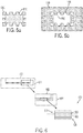
- FIGs. 4a and 4b A representative embodiment is shown in FIGs. 4a and 4b.
- FIG. 4a demonstrates a simple rectangle ultrasonic tool 1300.
- the ultrasonic tool 1300 When applied to a CMC section 1100 including a non-conformity, the ultrasonic tool 1300 creates a negative space or repair volume 1400 mimicking the geometry of the ultrasonic tool 1300.
- the application of the tool is not limited to planar removal. Removing the repair volume can include removing surface damage or damage which has translated through a thickness of the component. Further embodiments can include varying the removal depth.
- a selection of predetermined geometries for an ultrasonic tool can be included in a "tool box."
- the preselected tools within the tool box could contribute to a reduction in production or repair cycle times and costs.
- Preselected tool geometry can be determined based on defined non-conformities and cover a range of repairs.
- a predesigned tool can be utilized in embodiments applied in design changes and component modifications.
- a tool can be designed and applied repeatedly or several tools of the design can be made for multiple repeated applications to expedite a modification process.
- FIGs. 5a and 5b show a further embodiment of the present application.
- An ultrasonic tool 1300 is shown with a design including dovetail features 1500.
- the ultrasonic tool 1300 creates a repair volume 1400 in a CMC section 1100 having dovetails features 1500.
- the dovetail features 1500 of the repair volume 1400 in some embodiments can be applied as mechanical interlocking features with a new or replacement section of CMC (not shown).
- repair volume features including, for example, the dovetails described above, peg and biscuit holes, and tongue and groove joints, can enhance bonding with a new section of CMC by creating an increase in surface area.
- the new section of CMC can be capable of interlocking with the repair volume of the component under repair or modification via geometric features introduced by ultrasonic machining.
- Operation 400 includes forming a repair patch or preform.
- a repair portion 1200 from a component is removed having a shape which allows the positioning of a repair preform or patch.
- a preform or patch is manufactured with a geometry which can be determined as a function of repair volume, type of damage or modification, extent of damage or non-conformity, stress analysis and other such parameters. Geometry for a repair or replacement patch formed in Operation 400 can be determined based on repair volume depth, type and extent of damage, component stress analysis, and other such parameters.
- Operation 400 includes the preparation of a preform.
- a further embodiment can include the formation of preforms such as but not limited to a repair patch, repair packing and a replacement portion of CMC.
- Operation 400 includes a replacement portion selected in response to the non-conforming portion, the repairable or repair volume, the type of non-conformity.
- a pristine piece of CMC including a SiC/SiC composition is machined according to the determined repair portion and the removed portion of the component.
- the preform piece can be undersized slightly to accommodate a joining area.
- the amount of under-sizing can be a function of the joining scheme and in specific embodiments can be ⁇ 0.002-0.01".
- the preform can further be machined using various methods as discussed previously with regards to the repair volume, including ultrasonic machining.
- Operation 500 of Process 1000 further includes preparing an exposed repair surface and a preform surface for bonding a repair preform to a repair volume of a CMC component.
- the exposed repair surface of a repair volume created in a component is one part of a reaction region in which alternating layers of constituents for an equilibrium reaction are applied.
- the surface of a repair preform can form a complimentary surface to the reactive surface region.
- Operation 500 surface preparation includes applying alternating layers of at least two constituents. In one embodiment, alternating layers of carbon and a metallic (Si, Ti, Zr, and Hf) can be applied.
- FIG. 6 provides further detail regarding an alternating layer region 610.
- a surface of a repair volume 601 includes a first layer arrangement 620 having a first outer coating 625 including a first material.
- a repair preform 602 includes a second layer arrangement 630 having a second outer coating 635 including a second material. The composition of the second outer coating 635 being different from the composition of the first outer coating 625.
- a first arrangement of reaction layers 620 is formed by alternating at least one layer of a first constituent A and at least one layer of a second constituent B on the surface of the repair volume 601.
- a second arrangement of reaction layers 630 is formed by alternating layers of the first constituent A and the second constituent B on the surface of the repair preform 602.
- the surface of the repair volume 601 with a first outer coating 625 of the first arrangement of reaction layers 620 includes the first constituent A.
- the repair preform 602 with a second outer coating 635 of the second arrangement of reaction layers 630 includes the second constituent B.
- the prepared preform is positioned relative to the repair volume of the component for joining the two parts.
- Bringing the alternating layers of the parts together as shown in the highlighted view of FIG. 6 includes direct contact of the layers.
- the space between the outer coatings shown in FIG. 7 is for illustrative purposes to distinguish the two coatings.
- the two coatings are separate coatings of the two repair parts which are brought together when the repair preform is adjoined to the repair volume of the component.
- the coatings are in contact sufficient to create a non-equilibrium condition and to promote a reaction which forms a reaction bond between the parts.
- a repair surface of a repair volume is brought in contact with a surface of a repair preform.
- the repair surface and the preform surface are dimensioned to fit against each other so the arrangement of layers of one surface is within a reaction range of the other.
- the surface of the repair volume 601 and the surface of the repair preform 602 can be arranged or assembled where one surface fits against the other surface with the first outer surface 625 in contact with the second outer surface 635 to form a repaired component.
- the first and second outer surfaces 625,635 can be representative of alternating layer regions repeated or applied multiple times or in multiple places on the parts.
- the application of the alternating layers can be either sequential or at the same time along the surfaces 601,602.
- the materials applied can vary with the location of the regions in relation to the joint between parts. Joining locations and material applications of the arrangement of layers 610 can be a function of the surfaces and the joint geometry as well as the component materials.
- Operation 700 includes an integration reaction to form a bond between the surface of a repair volume on a component and a repair or replacement preform.
- the outer coatings applied in Operation 600 are placed in contact.
- One outer coating includes one part of a non-equilibrium condition and the other outer coating includes the other part of the non-equilibrium condition. Bringing the two coatings within a reactive range creates the non-equilibrium condition and starts the non-equilibrium reaction.
- the second outer coating 635 contains the second constituent B while the first outer coating 625 contains the first constituent A where A and B are selected to provide a non-equilibrium condition.
- the layers or regions in an arrangement can be distinguished by changes in at least one property when moving from one location to another of the coating arrangement.
- the changes can be abrupt or gradual.
- One example is an embodiment with a first region having a majority concentration of a first element.
- a relatively sharp change in concentration can be present when moving from the first region to a second region.
- the second region can have a majority concentration of a second element.
- a predominant concentration of the first element in the first region can gradually transition to a predominant concentration of the second element in the second region.
- a coating of alternating layers including the arrangements of layers 620,630 can be applied by various methods selected in relation to the joining material and the joint geometry.
- the alternating layers can be applied by at least one process such as, but not limited to, direct vapor deposition, chemical vapor deposition, plasma spraying, laser vapor deposition, slurry infiltration, liquid melt infiltration, and electron beam physical vapor deposition.
- layers can be 0.01 - 5 um thick.
- the joint surface can require a non-line-of-sight application; therefore a direct vapor deposition process can be used.
- Alternating layers can further refer to various patterns of layers or regions when the pattern is either regular or irregular depending on the number and type of layers and constituents. Layer patterns can be repeated once, multiple times or not at all. The pattern of the alternating layers can allow the selection of subsequent layers or constituents to be different in some way from the preceding or succeeding layer or constituent.
- An element or constituent composed within the alternating layers can include a single chemical element, a mix of multiple elements, a simple or complex compound, and various phases of the elements, compounds and materials.
- constituents can include elements such as titanium, zirconium, niobium, vanadium, hafnium, tantalum, molybdenum, chromium, tungsten, silicon, carbon, boron, aluminum, and nickel for example. The constituents are chosen in response to the creation of a non-equilibrium condition such as a system with a negative Gibbs free energy system as discussed in further detail below.
- a bond structure 710 is formed between the surface of the repair volume 601 and the surface of the repair preform 602 during an equilibrium reaction and includes a product AB of the equilibrium reaction in the bond layer 720.
- the bond structure 710 can include a graded bond structure having at least one compound formed from the first constituent A and the second constituent B.
- the bond layer can include an interlayer of constituent compounds such as carbides, nitrides, borides, silicides, and combinations thereof and a diffusion layer at the interface of the parts.
- the equilibrium reaction can take place in various atmospheres which can be selected based on the constituents or materials applied in the alternating layers and the parts.
- Parameters for an atmosphere can include temperature, pressure and composition. Temperature can be at room temperature or at an elevated temperature, for example. Pressure can be at various levels, such as but not limited to, ambient, atmospheric and in a vacuum.
- Atmosphere composition can include a pure gas or a mix of gases where the gas or gases can be nonreactive gases such as, but not limited to, argon and relatively reactive gases such as, but not limited to, hydrogen, oxygen and nitrogen.
- two repair parts 601,602 with alternating layers can be placed within an atmosphere.
- a gas composition in the atmosphere can include a reactant.
- the reactant supplied in the atmosphere can participate in the equilibrium reaction to form compounds of the reactant.
- the reactant can be, for example, nitrogen where the reaction creates nitrides in the resulting layers.
- Gases can provide advantages and disadvantages. For example, oxygen can aide in the wetting of some brazing applications while oxygen and moisture can be detrimental because of oxidation reactions.
- the application of an atmosphere and a gas reactant can be selected in response to the other constituents of the non-equilibrium reaction and the components being joined together.
- the temperature and chemical stability of a reaction system can be approached with complex layers and multiple constituents. Multiple constituents can be selected to produce a negative Gibbs free energy for the joint parameters of the components.
- An exemplary embodiment is shown in FIG. 8 where at least one additional constituent can be applied with a first constituent and a second constituent to create a self-propagating reaction to bind a repair part with a second repair part. Layers of the constituents are applied to the surface of each part at the joint location. The repair parts are assembled with the outer layers of each part in direct contact. The outer layers include complimentary constituents to create the non-equilibrium condition.
- a first outer surface layer 625 of a first repair part 601 includes the constituents A and B.
- a second outer surface layer 635 of a second repair part 602 includes the constituents A and E.
- Constituents A and B of the first outer surface layer 625 were chosen to produce a non-equilibrium condition when in proximity to the second outer surface layer 635 with constituents A and E.
- An additional layer is shown to include constituents B and E.
- An intermediate layer of constituent D is also shown as an alternative.
- a reaction can take place creating a bond or diffusion layer including various forms of AB, AE, and BE. These materials can be formed in a single compound, various phases within another and the like. Other layers can be created, as shown in FIG. 8 , with a product layer of constituents D and E and a product layer of constituents B and D.
- the chemical composition and physical microstructure of the bond layer and any intermediary layers are a function of the constituents and process parameters.
- the first constituent A and the second constituent B are selected to produce a thermodynamic non-equilibrium condition between the first and second constituents A, B.
- a self-propagating reaction of the first constituent A and the second constituent B can drive the thermodynamic non-equilibrium condition toward a thermodynamic equilibrium condition.
- a thermodynamic non-equilibrium condition is present in a system that is not in a state of balance and where there are net flows of matter or energy, phase changes, unbalanced potentials or driving forces.
- Non-equilibrium can be expressed in various ways including an unbalanced chemical potential and a negative Gibbs free energy, for example.
- An unbalanced chemical potential or diffusive non-equilibrium represents a system's potential for moving a reaction in a particular direction.
- Gibbs free energy or free enthalpy represents the obtainable process-initiating work of a thermodynamic system.
- a system can move from a negative to a positive Gibbs free energy by rearranging constituents to form structures and compounds with more free energy.
- a system with a negative Gibbs free energy attempts a transformation to minimize the chemical potential of the system and move to a positive Gibbs free energy.
- a system in non-equilibrium has the potential for initiating work and driving the system to equilibrium.
- the system can have the potential to drive a reaction with the selected materials and form an equilibrium state.
- the formation of an equilibrium state can be the formation of a reaction bond including the selected materials.
- the reaction bond forms as a result of the system being driven from a non-equilibrium state to an equilibrium state.
- the equilibrium state can include a reaction layer arrangement formed with at least a bond layer including a first material and a second material.
- Operation 800 includes facilitating a self-propagating reaction of a non-equilibrium condition by applying an energy to the contacting alternating layers between a repair preform adjoined with a repair component.
- a self-propagating reaction of a non-equilibrium condition by applying an energy to the contacting alternating layers between a repair preform adjoined with a repair component.
- the applied energy can facilitate such a reaction by accelerating the reaction rate.
- the equilibrium reaction can require a threshold energy to initiate the equilibrium reaction. The intensity and duration of the applied energy can vary as a function of the materials selected and the parameters of the equilibrium reaction.
- This energy can include electromagnetic energy, radiant energy, electrical energy, thermal energy and the like.
- Energy sources can include various forms such as, but are not limited to, the following:
- the energy source can be selected as a function of the size and complexity of the system and the materials being applied.
- one or more energy sources can be applied to a system concurrently, sequentially, and in variable locations, for example.
- Applied energy can facilitate an equilibrium reaction which drives the system from non-equilibrium to equilibrium.
- Equilibrium can be a partial completion of a reaction with remaining reactants available.
- Equilibrium is a status that is relative and can be non-static in nature.
- Facilitating can include accelerating the reaction between the constituents.
- a fixture or tool can be utilized to hold a repair patch in position with respect to a repair volume of a component.
- the tool can apply an external force to hold the repair preform in place and to provide a pressure for creating contact between layers of a first constituent on a repair preform and a second constituent on a surface or a repair volume where contact can drive a thermodynamic non-equilibrium reaction.
- the tooling material can be selected based on the source of an applied energy. For example, furnace heating could require a low expansion refractory alloy for tooling such as a TZM molybdenum alloy. In another example, applications of localized heating could employ stainless steel or nickel alloys.
- Process 1000 can include post-bonding Operation 900.
- Operation 900 can include a porosity reducing process which is applied following the equilibrium reaction to reduce porosity that may be present in the joint due to various factors related to the reaction.
- Self-propagating reactions can create continuous porous networks that can be infiltrated to provide various characteristics.
- Infiltrating materials can include Si-Zr, Si-Ti, Si-Hf, Si-Mo eutectic alloys. Materials for infiltration can include, but are not limited to, preceramic polymer, standard braze alloy, molten metal, metal compounds and so forth. The infiltrating material can be selected based on the component material, the constituents or diffusion materials, operating parameters and the like.
- a surface of a repair patch is prepared by applying at least one reaction layer of a first constituent in a first outer layer.
- a repair surface of a repair volume is prepared by applying at least one reaction layer of a second constituent in a second outer layer.
- the at least one reaction layer can include an arrangement of reaction layers formed by alternating at least one layer of the first constituent and at least one layer of the second constituent.
- the repair patch can be joined to the repair surface of the repair volume in the component using a submicron layer approach with reactive melt infiltration.
- Reactive melt infiltration can be used for some embodiments in areas in which operating temperatures stay below 2400°F being limited by the lowest melting point of system. In an embodiment for a SiC/SiC CMC, this can be silicon.
Landscapes
- Engineering & Computer Science (AREA)
- Chemical & Material Sciences (AREA)
- Ceramic Engineering (AREA)
- Materials Engineering (AREA)
- Mechanical Engineering (AREA)
- Manufacturing & Machinery (AREA)
- Structural Engineering (AREA)
- Organic Chemistry (AREA)
- General Engineering & Computer Science (AREA)
- Chemical Kinetics & Catalysis (AREA)
- Composite Materials (AREA)
- Turbine Rotor Nozzle Sealing (AREA)
Claims (16)
- Verfahren zur Modifizierung einer Keramikmatrixverbundmaterialkomponente, umfassend: ein Identifizieren einer nicht konformen Region der Keramikmatrixverbundmaterialkomponente, die in der Lage ist, in einem Gasturbinenmotor zu operieren;
ein Entfernen mindestens eines Abschnitts der nicht konformen Region der Keramikmatrixverbundmaterialkomponente, um eine freiliegende Fläche der Keramikmatrixverbundmaterialkomponente zu schaffen;
ein Vorbereiten einer Vorform in Reaktion auf das Entfernen mindestens eines Abschnitts der nicht konformen Region, wobei die Vorform konfiguriert ist, um den entfernten Abschnitt der nicht konformen Region zu ersetzen;
ein Anlegen einer Oberflächenregion mit reaktiven Bestandteilen auf mindestens eine der freiliegenden Fläche der Keramikmatrixverbundmaterialkomponente oder einer Fläche der Vorform, wobei die Oberflächenregion mit reaktiven Bestandteilen einen ersten Bestandteil und einen zweiten Bestandteil umfasst, die in der Lage sind, einen thermodynamischen Ungleichgewichtszustand zwischen dem ersten Bestandteil und dem zweiten Bestandteil zu erzeugen, wobei eine sich selbst verbreitende Reaktion des ersten Bestandteils und des zweiten Bestandteils in der Lage ist, den thermodynamischen Ungleichgewichtszustand zu einem thermodynamischen Gleichgewichtszustand zu treiben, wobei das Anlegen der Oberflächenregion mit reaktiven Bestandteilen auf die mindestens eine der freiliegenden Oberfläche der Keramikmatrixverbundmaterialkomponente oder der Oberfläche der Vorform umfasst:ein Anlegen einer ersten Vielzahl von Schichten des ersten Bestandteils und des zweiten Bestandteils auf die freiliegende Oberfläche der Keramikmatrixverbundmaterialkomponente, um eine erste Außenbeschichtung zu bilden, wobei die erste Außenbeschichtung den ersten Bestandteil enthält; undein Anlegen einer zweiten Vielzahl von Schichten des ersten Bestandteils und des zweiten Bestandteils auf die Oberfläche der Vorform, um eine zweite Außenbeschichtung zu bilden, wobei die zweite Außenbeschichtung den zweiten Bestandteil enthält;ein Positionieren der Vorform, um eine Kontaktregion zwischen der freiliegenden Oberfläche der Keramikmatrixverbundmaterialkomponente und der Vorform bereitzustellen, wobei die Oberflächenregion mit reaktiven Bestandteilen zwischen der Keramikmatrixverbundmaterialkomponente und der Vorform positioniert ist; undReagieren der Oberflächenregion mit reaktiven Bestandteilen in einer sich selbst verbreitenden Reaktion an der Kontaktregion, um eine Verbindungsstruktur zwischen der freiliegenden Oberfläche der Keramikmatrixverbundmaterialkomponente und der Vorform zu bilden. - Verfahren nach Anspruch 1, wobei das Entfernen des mindestens einen Abschnitts der nicht konformen Region eine Ultraschallbearbeitung der Keramikmatrixverbundmaterialkomponente umfasst, um die freiliegende Oberfläche der Keramikmatrixverbundmaterialkomponente zu erzeugen.
- Verfahren nach Anspruch 1, wobei das Anlegen der Oberfläche mit reaktiven Bestandteilen ein Anlegen wechselnder Schichten des ersten Bestandteils und des zweiten Bestandteils umfasst.
- Verfahren nach Anspruch 1, ferner umfassend ein Anlegen einer Energiequelle an die Oberflächenregion mit reaktiven Bestandteilen, um die sich selbst verbreitende Reaktion zu erleichtern.
- Verfahren nach Anspruch 4, wobei das Anlegen der Energiequelle die sich selbst verbreitende Reaktion beschleunigt.
- Verfahren nach Anspruch 4, wobei das Anlegen der Energiequelle die sich selbst verbreitende Reaktion initiiert.
- Verfahren nach Anspruch 4, wobei das Anlegen der Energiequelle ein Infiltrieren der Oberflächenregion mit reaktiven Bestandteilen mit einem eutektischem Schmelzmaterial umfasst.
- Verfahren nach Anspruch 7, wobei ein Ungleichgewichtszustand zwischen dem eutektischen Schmelzmaterial und mindestens einem des ersten Bestandteils oder des zweiten Bestandteils die Gleichgewichtsreaktion antriebt, um eine Bindungsstruktur mit einem Reaktionsprodukt der Gleichgewichtsreaktion zu bilden.
- Verfahren nach Anspruch 7, wobei das eutektische Schmelzmaterial mindestens eines aus Si-Mo, Si-Zr, Si-Hf, Si-Ti, Si-Ta, Si-Yb oder Si-Y ist.
- Verfahren nach Anspruch 1, ferner umfassend ein Anlegen einer zerstörungsfreien Evaluierungstechnik, um die nicht konforme Region der Keramikmatrixverbundmaterialkomponente zu identifizieren.
- Verfahren nach Anspruch 3, wobei die abwechselnden Schichten des ersten Bestandteils und des zweiten Bestandteils Titan, Zirkonium, Niobium, Vanadium, Hafnium, Tantalum, Molybdenum, Chrom, Wolfram, Silizium, Kohlenstoff, Bor, Aluminium, Nickel oder Kombinationen daraus enthalten.
- Verfahren nach Anspruch 1, wobei das Entfernen des Abschnitts der nicht konformen Region der Keramikmatrixverbundmaterialkomponente eine Ultraschallbearbeitung der Keramikmatrixverbundmaterialkomponente umfasst, um ein Reparaturvolumen zu bilden, das geometrische Merkmale definiert, die konfiguriert sind, um sich mit der Vorform zu verschränken.
- Verfahren nach Anspruch 1, wobei die Vorform ein Ersatzabschnitt eines Keramimatrixverbundmaterials ist.
- System, umfassend:eine Außenfläche einer durch Entfernen einer abweichenden Region erzeugten Keramikmatrixverbundmaterialkomponente, wobei die Außenfläche der Keramikmatrixverbundmaterialkomponente einen Oberflächenschichtsatz aufweist, der mindestens einen eines ersten Bestandteils und eines zweiten Bestandteils enthält;und eine Vorformstruktur, die in Reaktion darauf gebildet wird, dass die abweichende Region einen Vorformschichtsatz aufweist, wobei der Vorformschichtsatz mindestens eines des ersten Bestandteils und des zweiten Bestandteils enthält,wobei der mindestens eine des ersten Bestandteils und des zweiten Bestandteils des Oberflächenschichtsatzes und des Vorformschichtsatzes in der Lage sind, einen thermodynamischen Ungleichgewichtszustand zwischen dem ersten Bestandteil und dem zweiten Bestandteil zu erzeugen, wobei eine sich selbst verbreitende Reaktion des ersten Bestandteils und des zweiten Bestandteils in der Lage ist, den thermodynamischen Ungleichgewichtszustand zu einem thermodynamischen Gleichgewichtszustand zu treiben, wobei der Oberflächenschichtsatz der Keramikmatrixverbundmaterialkomponente eine erste Vielzahl von Schichten des ersten Bestandteils und des zweiten Bestandteils enthält, die eine erste Außenbeschichtung bilden, wobei die erste Außenbeschichtung den ersten Bestandteil enthält und wobei der Vorformschichtsatz der Vorform eine zweite Vielzahl von Schichten des ersten Bestandteils und des zweiten Bestandteils enthält, die einen zweite Außenbeschichtung bilden, wobei die zweite Außenbeschichtung den zweiten Bestandteil enthält.
- System nach Anspruch 14, wobei der Oberflächenschichtsatz und der Vorformschichtsatz jeweils abwechselnde Schichten des ersten Bestandteils und des zweiten Bestandteils enthalten.
- System mach Anspruch 15, wobei die abwechselnden Schichten des ersten Bestandteils und des zweiten Bestandteils Titan, Zirkonium, Niobium, Vanadium, Hafnium, Tantalum, Molybdenum, Chrom, Wolfram, Silizium, Kohlenstoff, Bor, Aluminium, Nickel oder Kombinationen daraus enthalten.
Applications Claiming Priority (2)
| Application Number | Priority Date | Filing Date | Title |
|---|---|---|---|
| US201361802250P | 2013-03-15 | 2013-03-15 | |
| PCT/US2013/078271 WO2014149124A1 (en) | 2013-03-15 | 2013-12-30 | Ceramic matrix composite repair by reactive processing and mechanical interlocking |
Publications (2)
| Publication Number | Publication Date |
|---|---|
| EP2970025A1 EP2970025A1 (de) | 2016-01-20 |
| EP2970025B1 true EP2970025B1 (de) | 2020-02-12 |
Family
ID=51528299
Family Applications (1)
| Application Number | Title | Priority Date | Filing Date |
|---|---|---|---|
| EP13821420.0A Active EP2970025B1 (de) | 2013-03-15 | 2013-12-30 | Reparatur eines keramikmatrix-verbundwerkstoffes durch reaktive verarbeitung und mechanische verriegelung |
Country Status (3)
| Country | Link |
|---|---|
| US (1) | US9366140B2 (de) |
| EP (1) | EP2970025B1 (de) |
| WO (1) | WO2014149124A1 (de) |
Cited By (2)
| Publication number | Priority date | Publication date | Assignee | Title |
|---|---|---|---|---|
| EP4299551A1 (de) * | 2022-06-28 | 2024-01-03 | General Electric Company | Verbundkomponenten und verfahren zur verhinderung des flusses von infiltrierten komponenten während der rückfiltration |
| FR3164141A1 (fr) * | 2024-07-08 | 2026-01-09 | Safran Ceramics | Procédé de remplacement de partie manquante sur une pièce matériau composite à matrice céramique |
Families Citing this family (25)
| Publication number | Priority date | Publication date | Assignee | Title |
|---|---|---|---|---|
| US9366140B2 (en) | 2013-03-15 | 2016-06-14 | Rolls-Royce Corporation | Ceramic matrix composite repair by reactive processing and mechanical interlocking |
| US9573354B2 (en) * | 2013-03-15 | 2017-02-21 | Rolls-Royce Corporation | Layered deposition for reactive joining of composites |
| CN103354210B (zh) * | 2013-06-27 | 2016-08-10 | 清华大学 | 一种键合方法及采用该键合方法形成的键合结构 |
| US20150003997A1 (en) * | 2013-07-01 | 2015-01-01 | United Technologies Corporation | Method of forming hybrid metal ceramic components |
| US9719420B2 (en) * | 2014-06-02 | 2017-08-01 | General Electric Company | Gas turbine component and process for producing gas turbine component |
| US9512505B2 (en) | 2014-10-23 | 2016-12-06 | General Electric Company | Methods and compositions for repair of composite materials |
| US10717681B2 (en) | 2014-12-05 | 2020-07-21 | Rolls-Royce Corporation | Method of making a ceramic matrix composite (CMC) component including a protective ceramic layer |
| US10458653B2 (en) * | 2015-06-05 | 2019-10-29 | Rolls-Royce Corporation | Machinable CMC insert |
| US10465534B2 (en) | 2015-06-05 | 2019-11-05 | Rolls-Royce North American Technologies, Inc. | Machinable CMC insert |
| US10472976B2 (en) * | 2015-06-05 | 2019-11-12 | Rolls-Royce Corporation | Machinable CMC insert |
| US9745849B2 (en) * | 2015-06-26 | 2017-08-29 | General Electric Company | Methods for treating field operated components |
| JP6824839B2 (ja) * | 2017-07-11 | 2021-02-03 | 三菱重工業株式会社 | セラミック基複合材料の補修方法及びセラミック基複合部材 |
| US11028696B2 (en) | 2017-08-07 | 2021-06-08 | General Electric Company | Ceramic matrix composite airfoil repair |
| US12145893B2 (en) | 2018-08-17 | 2024-11-19 | Rtx Corporation | Coating repair for ceramic matrix composite (CMC) substrates |
| US11459908B2 (en) * | 2018-08-31 | 2022-10-04 | General Electric Company | CMC component including directionally controllable CMC insert and method of fabrication |
| US11097384B2 (en) | 2019-01-23 | 2021-08-24 | General Electric Company | Mechanical ceramic matrix composite (CMS) repair |
| FR3096678B1 (fr) | 2019-05-27 | 2021-05-21 | Safran Ceram | Procede de reparation d’une piece en cmc et dispositif |
| US20210147303A1 (en) * | 2019-11-15 | 2021-05-20 | Rolls-Royce High Temperature Composites Inc. | Method to repair cmc components |
| AU2020204380A1 (en) * | 2019-11-27 | 2021-06-10 | University Of Southern Queensland | A method and patch for defect repair |
| US11746059B2 (en) | 2020-02-26 | 2023-09-05 | General Electric Companhy | Induction melt infiltration processing of ceramic matrix composite components |
| US11969962B2 (en) | 2020-09-25 | 2024-04-30 | General Electric Company | Method for repairing composite components and associated infiltration systems and methods |
| US12331395B2 (en) | 2021-01-15 | 2025-06-17 | Rtx Corporation | Method of repairing ceramic composite articles |
| CN113045324A (zh) * | 2021-03-28 | 2021-06-29 | 西北工业大学 | 一种磨损到寿C/C-SiC刹车盘的修复再利用方法 |
| US12180122B2 (en) | 2021-12-22 | 2024-12-31 | Rolls-Royce High Temperature Composites, Inc. | Joining material with silicon carbide particles and reactive additives |
| US12343811B2 (en) * | 2023-06-23 | 2025-07-01 | Hamilton Sundstrand Corporation | Systems and methods for ultrasonic repair |
Citations (2)
| Publication number | Priority date | Publication date | Assignee | Title |
|---|---|---|---|---|
| DE10035111A1 (de) * | 2000-03-24 | 2001-10-31 | Industrieanlagen Betriebsges | Ultra-Leichtgewichts-Träger und Verfahren zu seiner Herstellung |
| US20100038409A1 (en) * | 2007-04-30 | 2010-02-18 | Airbus Deutschland Gmbh | Joining Method For Joining Components |
Family Cites Families (17)
| Publication number | Priority date | Publication date | Assignee | Title |
|---|---|---|---|---|
| GB925509A (en) | 1959-07-29 | 1963-05-08 | Ass Elect Ind | Ceramic to metal bond |
| US4800065A (en) | 1986-12-19 | 1989-01-24 | Martin Marietta Corporation | Process for making ceramic-ceramic composites and products thereof |
| US5306565A (en) | 1990-09-18 | 1994-04-26 | Norton Company | High temperature ceramic composite |
| US5381944A (en) | 1993-11-04 | 1995-01-17 | The Regents Of The University Of California | Low temperature reactive bonding |
| US5503703A (en) | 1994-01-10 | 1996-04-02 | Dahotre; Narendra B. | Laser bonding process |
| US5538795B1 (en) | 1994-07-15 | 2000-04-18 | Univ California | Ignitable heterogeneous stratified structure for the propagation of an internal exothermic chemical reaction along an expanding wavefront and method making same |
| US5599468A (en) | 1994-10-03 | 1997-02-04 | Frederick M. Mako | Pulsed electron beam joining of materials |
| DE19636223C2 (de) | 1996-09-06 | 1999-07-08 | Deutsch Zentr Luft & Raumfahrt | Verfahren zum dauerhaften Verbinden von wenigstens zwei Bauteilkomponenten zu einem Formkörper |
| DE19734211C2 (de) | 1997-08-07 | 2001-08-30 | Forschungszentrum Juelich Gmbh | Verfahren zum Verlöten zweier Keramiken oder einer Keramik mit einem Metall |
| US6294125B1 (en) | 1998-12-23 | 2001-09-25 | Dow Corning Corporation | Method for changing the dielectric properties of a ceramic matrix composite |
| US6413578B1 (en) * | 2000-10-12 | 2002-07-02 | General Electric Company | Method for repairing a thermal barrier coating and repaired coating formed thereby |
| US6554179B2 (en) | 2001-07-06 | 2003-04-29 | General Atomics | Reaction brazing of tungsten or molybdenum body to carbonaceous support |
| FR2872072B1 (fr) | 2004-06-24 | 2006-09-29 | Snecma Propulsion Solide Sa | Procede de brasage de pieces en materiau composite thermostructural siliciure |
| AT7807U1 (de) | 2004-09-06 | 2005-09-26 | Plansee Ag | Werkstoffverbund |
| US7648605B2 (en) | 2007-05-17 | 2010-01-19 | Siemens Energy, Inc. | Process for applying a thermal barrier coating to a ceramic matrix composite |
| AT12919U1 (de) | 2011-11-25 | 2013-02-15 | Plansee Se | Verfahren zur herstellung eines hochtemperaturfesten verbundkörpers |
| US9366140B2 (en) | 2013-03-15 | 2016-06-14 | Rolls-Royce Corporation | Ceramic matrix composite repair by reactive processing and mechanical interlocking |
-
2013
- 2013-12-27 US US14/141,976 patent/US9366140B2/en active Active
- 2013-12-30 WO PCT/US2013/078271 patent/WO2014149124A1/en not_active Ceased
- 2013-12-30 EP EP13821420.0A patent/EP2970025B1/de active Active
Patent Citations (2)
| Publication number | Priority date | Publication date | Assignee | Title |
|---|---|---|---|---|
| DE10035111A1 (de) * | 2000-03-24 | 2001-10-31 | Industrieanlagen Betriebsges | Ultra-Leichtgewichts-Träger und Verfahren zu seiner Herstellung |
| US20100038409A1 (en) * | 2007-04-30 | 2010-02-18 | Airbus Deutschland Gmbh | Joining Method For Joining Components |
Cited By (2)
| Publication number | Priority date | Publication date | Assignee | Title |
|---|---|---|---|---|
| EP4299551A1 (de) * | 2022-06-28 | 2024-01-03 | General Electric Company | Verbundkomponenten und verfahren zur verhinderung des flusses von infiltrierten komponenten während der rückfiltration |
| FR3164141A1 (fr) * | 2024-07-08 | 2026-01-09 | Safran Ceramics | Procédé de remplacement de partie manquante sur une pièce matériau composite à matrice céramique |
Also Published As
| Publication number | Publication date |
|---|---|
| US20140272248A1 (en) | 2014-09-18 |
| WO2014149124A1 (en) | 2014-09-25 |
| US9366140B2 (en) | 2016-06-14 |
| EP2970025A1 (de) | 2016-01-20 |
Similar Documents
| Publication | Publication Date | Title |
|---|---|---|
| EP2970025B1 (de) | Reparatur eines keramikmatrix-verbundwerkstoffes durch reaktive verarbeitung und mechanische verriegelung | |
| US9573354B2 (en) | Layered deposition for reactive joining of composites | |
| EP2366678B1 (de) | Oberfläche mit großer Toleranz für Keramikmatrix-Verbundstoffkomponente | |
| US9981438B2 (en) | Pre-form ceramic matrix composite cavity and a ceramic matrix composite component | |
| US8956478B2 (en) | Process for joining refractory ceramic parts by spark plasma sintering (SPS) | |
| US10465534B2 (en) | Machinable CMC insert | |
| US10458653B2 (en) | Machinable CMC insert | |
| US10406640B2 (en) | Method for repairing ceramic matrix composite (CMC) articles | |
| JP4910096B2 (ja) | ガスタービン構成部品に研磨コーティングを施工する方法 | |
| US10000422B2 (en) | Ceramic to ceramic joining method | |
| CN106870016B (zh) | 陶瓷基质复合物构件和生产陶瓷基质复合物构件的过程 | |
| US10472976B2 (en) | Machinable CMC insert | |
| US10401028B2 (en) | Machinable CMC insert | |
| EP3109043B1 (de) | Verfahren zur integralen verbindung von infiltrierten keramischem matrix-verbundstoffen | |
| Hernandez et al. | An innovative joint structure for brazing Cf/SiC composite to titanium alloy | |
| CN105818253A (zh) | 复合工具和形成复合部件的方法 | |
| Appendino et al. | Proposal for a new technique to join CFC composites to copper | |
| US7311790B2 (en) | Hybrid structure using ceramic tiles and method of manufacture | |
| Kim et al. | Interfacial microstructure of partial transient liquid phase bonded Si3N4-to-Inconel 718 joints | |
| Meiirbekov et al. | Multimatrix Composite Materials for Rocket Nozzle Manufacturing: A Comparative Review | |
| Ferraris et al. | Integration and joining of ceramic matrix composites | |
| Vandehaar et al. | Laser cladding of thermal barrier coatings | |
| Li et al. | Joining of Cf/SiC composite with Cu–Pd–V filler alloy and Mo interlayer | |
| Xiong et al. | Joining of Cf/SiC composite and TC4 using Ag-Al-Ti active brazing alloy | |
| Chernenko | Friction welding AD1 aluminium to 12Kh18N10T steel |
Legal Events
| Date | Code | Title | Description |
|---|---|---|---|
| PUAI | Public reference made under article 153(3) epc to a published international application that has entered the european phase |
Free format text: ORIGINAL CODE: 0009012 |
|
| 17P | Request for examination filed |
Effective date: 20151012 |
|
| AK | Designated contracting states |
Kind code of ref document: A1 Designated state(s): AL AT BE BG CH CY CZ DE DK EE ES FI FR GB GR HR HU IE IS IT LI LT LU LV MC MK MT NL NO PL PT RO RS SE SI SK SM TR |
|
| AX | Request for extension of the european patent |
Extension state: BA ME |
|
| RIN1 | Information on inventor provided before grant (corrected) |
Inventor name: CHAMBERLAIN, ADAM LEE |
|
| DAX | Request for extension of the european patent (deleted) | ||
| STAA | Information on the status of an ep patent application or granted ep patent |
Free format text: STATUS: EXAMINATION IS IN PROGRESS |
|
| 17Q | First examination report despatched |
Effective date: 20180508 |
|
| REG | Reference to a national code |
Ref country code: DE Ref legal event code: R079 Ref document number: 602013065783 Country of ref document: DE Free format text: PREVIOUS MAIN CLASS: C04B0035640000 Ipc: C04B0035571000 |
|
| RIC1 | Information provided on ipc code assigned before grant |
Ipc: C04B 35/80 20060101ALI20190617BHEP Ipc: F01D 5/00 20060101ALI20190617BHEP Ipc: C22C 1/04 20060101ALI20190617BHEP Ipc: C04B 37/02 20060101ALI20190617BHEP Ipc: F01D 5/28 20060101ALI20190617BHEP Ipc: C04B 35/571 20060101AFI20190617BHEP Ipc: C04B 35/573 20060101ALI20190617BHEP Ipc: B22F 5/10 20060101ALI20190617BHEP |
|
| GRAP | Despatch of communication of intention to grant a patent |
Free format text: ORIGINAL CODE: EPIDOSNIGR1 |
|
| STAA | Information on the status of an ep patent application or granted ep patent |
Free format text: STATUS: GRANT OF PATENT IS INTENDED |
|
| INTG | Intention to grant announced |
Effective date: 20190906 |
|
| GRAS | Grant fee paid |
Free format text: ORIGINAL CODE: EPIDOSNIGR3 |
|
| GRAA | (expected) grant |
Free format text: ORIGINAL CODE: 0009210 |
|
| STAA | Information on the status of an ep patent application or granted ep patent |
Free format text: STATUS: THE PATENT HAS BEEN GRANTED |
|
| AK | Designated contracting states |
Kind code of ref document: B1 Designated state(s): AL AT BE BG CH CY CZ DE DK EE ES FI FR GB GR HR HU IE IS IT LI LT LU LV MC MK MT NL NO PL PT RO RS SE SI SK SM TR |
|
| REG | Reference to a national code |
Ref country code: GB Ref legal event code: FG4D |
|
| REG | Reference to a national code |
Ref country code: CH Ref legal event code: EP |
|
| REG | Reference to a national code |
Ref country code: AT Ref legal event code: REF Ref document number: 1231906 Country of ref document: AT Kind code of ref document: T Effective date: 20200215 |
|
| REG | Reference to a national code |
Ref country code: IE Ref legal event code: FG4D |
|
| REG | Reference to a national code |
Ref country code: DE Ref legal event code: R096 Ref document number: 602013065783 Country of ref document: DE |
|
| PG25 | Lapsed in a contracting state [announced via postgrant information from national office to epo] |
Ref country code: NO Free format text: LAPSE BECAUSE OF FAILURE TO SUBMIT A TRANSLATION OF THE DESCRIPTION OR TO PAY THE FEE WITHIN THE PRESCRIBED TIME-LIMIT Effective date: 20200512 Ref country code: RS Free format text: LAPSE BECAUSE OF FAILURE TO SUBMIT A TRANSLATION OF THE DESCRIPTION OR TO PAY THE FEE WITHIN THE PRESCRIBED TIME-LIMIT Effective date: 20200212 Ref country code: FI Free format text: LAPSE BECAUSE OF FAILURE TO SUBMIT A TRANSLATION OF THE DESCRIPTION OR TO PAY THE FEE WITHIN THE PRESCRIBED TIME-LIMIT Effective date: 20200212 |
|
| REG | Reference to a national code |
Ref country code: LT Ref legal event code: MG4D |
|
| REG | Reference to a national code |
Ref country code: NL Ref legal event code: MP Effective date: 20200212 |
|
| PG25 | Lapsed in a contracting state [announced via postgrant information from national office to epo] |
Ref country code: IS Free format text: LAPSE BECAUSE OF FAILURE TO SUBMIT A TRANSLATION OF THE DESCRIPTION OR TO PAY THE FEE WITHIN THE PRESCRIBED TIME-LIMIT Effective date: 20200612 Ref country code: SE Free format text: LAPSE BECAUSE OF FAILURE TO SUBMIT A TRANSLATION OF THE DESCRIPTION OR TO PAY THE FEE WITHIN THE PRESCRIBED TIME-LIMIT Effective date: 20200212 Ref country code: LV Free format text: LAPSE BECAUSE OF FAILURE TO SUBMIT A TRANSLATION OF THE DESCRIPTION OR TO PAY THE FEE WITHIN THE PRESCRIBED TIME-LIMIT Effective date: 20200212 Ref country code: HR Free format text: LAPSE BECAUSE OF FAILURE TO SUBMIT A TRANSLATION OF THE DESCRIPTION OR TO PAY THE FEE WITHIN THE PRESCRIBED TIME-LIMIT Effective date: 20200212 Ref country code: BG Free format text: LAPSE BECAUSE OF FAILURE TO SUBMIT A TRANSLATION OF THE DESCRIPTION OR TO PAY THE FEE WITHIN THE PRESCRIBED TIME-LIMIT Effective date: 20200512 Ref country code: GR Free format text: LAPSE BECAUSE OF FAILURE TO SUBMIT A TRANSLATION OF THE DESCRIPTION OR TO PAY THE FEE WITHIN THE PRESCRIBED TIME-LIMIT Effective date: 20200513 |
|
| PG25 | Lapsed in a contracting state [announced via postgrant information from national office to epo] |
Ref country code: NL Free format text: LAPSE BECAUSE OF FAILURE TO SUBMIT A TRANSLATION OF THE DESCRIPTION OR TO PAY THE FEE WITHIN THE PRESCRIBED TIME-LIMIT Effective date: 20200212 |
|
| PG25 | Lapsed in a contracting state [announced via postgrant information from national office to epo] |
Ref country code: PT Free format text: LAPSE BECAUSE OF FAILURE TO SUBMIT A TRANSLATION OF THE DESCRIPTION OR TO PAY THE FEE WITHIN THE PRESCRIBED TIME-LIMIT Effective date: 20200705 Ref country code: LT Free format text: LAPSE BECAUSE OF FAILURE TO SUBMIT A TRANSLATION OF THE DESCRIPTION OR TO PAY THE FEE WITHIN THE PRESCRIBED TIME-LIMIT Effective date: 20200212 Ref country code: CZ Free format text: LAPSE BECAUSE OF FAILURE TO SUBMIT A TRANSLATION OF THE DESCRIPTION OR TO PAY THE FEE WITHIN THE PRESCRIBED TIME-LIMIT Effective date: 20200212 Ref country code: RO Free format text: LAPSE BECAUSE OF FAILURE TO SUBMIT A TRANSLATION OF THE DESCRIPTION OR TO PAY THE FEE WITHIN THE PRESCRIBED TIME-LIMIT Effective date: 20200212 Ref country code: SK Free format text: LAPSE BECAUSE OF FAILURE TO SUBMIT A TRANSLATION OF THE DESCRIPTION OR TO PAY THE FEE WITHIN THE PRESCRIBED TIME-LIMIT Effective date: 20200212 Ref country code: EE Free format text: LAPSE BECAUSE OF FAILURE TO SUBMIT A TRANSLATION OF THE DESCRIPTION OR TO PAY THE FEE WITHIN THE PRESCRIBED TIME-LIMIT Effective date: 20200212 Ref country code: SM Free format text: LAPSE BECAUSE OF FAILURE TO SUBMIT A TRANSLATION OF THE DESCRIPTION OR TO PAY THE FEE WITHIN THE PRESCRIBED TIME-LIMIT Effective date: 20200212 Ref country code: DK Free format text: LAPSE BECAUSE OF FAILURE TO SUBMIT A TRANSLATION OF THE DESCRIPTION OR TO PAY THE FEE WITHIN THE PRESCRIBED TIME-LIMIT Effective date: 20200212 Ref country code: ES Free format text: LAPSE BECAUSE OF FAILURE TO SUBMIT A TRANSLATION OF THE DESCRIPTION OR TO PAY THE FEE WITHIN THE PRESCRIBED TIME-LIMIT Effective date: 20200212 |
|
| REG | Reference to a national code |
Ref country code: DE Ref legal event code: R097 Ref document number: 602013065783 Country of ref document: DE |
|
| REG | Reference to a national code |
Ref country code: AT Ref legal event code: MK05 Ref document number: 1231906 Country of ref document: AT Kind code of ref document: T Effective date: 20200212 |
|
| PLBE | No opposition filed within time limit |
Free format text: ORIGINAL CODE: 0009261 |
|
| STAA | Information on the status of an ep patent application or granted ep patent |
Free format text: STATUS: NO OPPOSITION FILED WITHIN TIME LIMIT |
|
| 26N | No opposition filed |
Effective date: 20201113 |
|
| PG25 | Lapsed in a contracting state [announced via postgrant information from national office to epo] |
Ref country code: IT Free format text: LAPSE BECAUSE OF FAILURE TO SUBMIT A TRANSLATION OF THE DESCRIPTION OR TO PAY THE FEE WITHIN THE PRESCRIBED TIME-LIMIT Effective date: 20200212 Ref country code: AT Free format text: LAPSE BECAUSE OF FAILURE TO SUBMIT A TRANSLATION OF THE DESCRIPTION OR TO PAY THE FEE WITHIN THE PRESCRIBED TIME-LIMIT Effective date: 20200212 |
|
| PG25 | Lapsed in a contracting state [announced via postgrant information from national office to epo] |
Ref country code: SI Free format text: LAPSE BECAUSE OF FAILURE TO SUBMIT A TRANSLATION OF THE DESCRIPTION OR TO PAY THE FEE WITHIN THE PRESCRIBED TIME-LIMIT Effective date: 20200212 Ref country code: PL Free format text: LAPSE BECAUSE OF FAILURE TO SUBMIT A TRANSLATION OF THE DESCRIPTION OR TO PAY THE FEE WITHIN THE PRESCRIBED TIME-LIMIT Effective date: 20200212 |
|
| REG | Reference to a national code |
Ref country code: CH Ref legal event code: PL |
|
| GBPC | Gb: european patent ceased through non-payment of renewal fee |
Effective date: 20201230 |
|
| PG25 | Lapsed in a contracting state [announced via postgrant information from national office to epo] |
Ref country code: MC Free format text: LAPSE BECAUSE OF FAILURE TO SUBMIT A TRANSLATION OF THE DESCRIPTION OR TO PAY THE FEE WITHIN THE PRESCRIBED TIME-LIMIT Effective date: 20200212 |
|
| REG | Reference to a national code |
Ref country code: BE Ref legal event code: MM Effective date: 20201231 |
|
| PG25 | Lapsed in a contracting state [announced via postgrant information from national office to epo] |
Ref country code: LU Free format text: LAPSE BECAUSE OF NON-PAYMENT OF DUE FEES Effective date: 20201230 Ref country code: IE Free format text: LAPSE BECAUSE OF NON-PAYMENT OF DUE FEES Effective date: 20201230 |
|
| PG25 | Lapsed in a contracting state [announced via postgrant information from national office to epo] |
Ref country code: LI Free format text: LAPSE BECAUSE OF NON-PAYMENT OF DUE FEES Effective date: 20201231 Ref country code: GB Free format text: LAPSE BECAUSE OF NON-PAYMENT OF DUE FEES Effective date: 20201230 Ref country code: CH Free format text: LAPSE BECAUSE OF NON-PAYMENT OF DUE FEES Effective date: 20201231 |
|
| PG25 | Lapsed in a contracting state [announced via postgrant information from national office to epo] |
Ref country code: TR Free format text: LAPSE BECAUSE OF FAILURE TO SUBMIT A TRANSLATION OF THE DESCRIPTION OR TO PAY THE FEE WITHIN THE PRESCRIBED TIME-LIMIT Effective date: 20200212 Ref country code: MT Free format text: LAPSE BECAUSE OF FAILURE TO SUBMIT A TRANSLATION OF THE DESCRIPTION OR TO PAY THE FEE WITHIN THE PRESCRIBED TIME-LIMIT Effective date: 20200212 Ref country code: CY Free format text: LAPSE BECAUSE OF FAILURE TO SUBMIT A TRANSLATION OF THE DESCRIPTION OR TO PAY THE FEE WITHIN THE PRESCRIBED TIME-LIMIT Effective date: 20200212 |
|
| PG25 | Lapsed in a contracting state [announced via postgrant information from national office to epo] |
Ref country code: MK Free format text: LAPSE BECAUSE OF FAILURE TO SUBMIT A TRANSLATION OF THE DESCRIPTION OR TO PAY THE FEE WITHIN THE PRESCRIBED TIME-LIMIT Effective date: 20200212 Ref country code: AL Free format text: LAPSE BECAUSE OF FAILURE TO SUBMIT A TRANSLATION OF THE DESCRIPTION OR TO PAY THE FEE WITHIN THE PRESCRIBED TIME-LIMIT Effective date: 20200212 |
|
| PG25 | Lapsed in a contracting state [announced via postgrant information from national office to epo] |
Ref country code: BE Free format text: LAPSE BECAUSE OF NON-PAYMENT OF DUE FEES Effective date: 20201231 |
|
| P01 | Opt-out of the competence of the unified patent court (upc) registered |
Effective date: 20230528 |
|
| PGFP | Annual fee paid to national office [announced via postgrant information from national office to epo] |
Ref country code: FR Payment date: 20251230 Year of fee payment: 13 |
|
| PGFP | Annual fee paid to national office [announced via postgrant information from national office to epo] |
Ref country code: DE Payment date: 20251229 Year of fee payment: 13 |