EP2971323B1 - Machine à laver le linge et procédé de fonctionnement s'y rapportant - Google Patents
Machine à laver le linge et procédé de fonctionnement s'y rapportant Download PDFInfo
- Publication number
- EP2971323B1 EP2971323B1 EP13703774.3A EP13703774A EP2971323B1 EP 2971323 B1 EP2971323 B1 EP 2971323B1 EP 13703774 A EP13703774 A EP 13703774A EP 2971323 B1 EP2971323 B1 EP 2971323B1
- Authority
- EP
- European Patent Office
- Prior art keywords
- water
- hermetically
- container
- structured
- closable container
- Prior art date
- Legal status (The legal status is an assumption and is not a legal conclusion. Google has not performed a legal analysis and makes no representation as to the accuracy of the status listed.)
- Active
Links
Images


Classifications
-
- D—TEXTILES; PAPER
- D06—TREATMENT OF TEXTILES OR THE LIKE; LAUNDERING; FLEXIBLE MATERIALS NOT OTHERWISE PROVIDED FOR
- D06F—LAUNDERING, DRYING, IRONING, PRESSING OR FOLDING TEXTILE ARTICLES
- D06F39/00—Details of washing machines not specific to a single type of machines covered by groups D06F9/00 - D06F27/00
- D06F39/02—Devices for adding soap or other washing agents
- D06F39/028—Arrangements for selectively supplying water to detergent compartments
-
- D—TEXTILES; PAPER
- D06—TREATMENT OF TEXTILES OR THE LIKE; LAUNDERING; FLEXIBLE MATERIALS NOT OTHERWISE PROVIDED FOR
- D06F—LAUNDERING, DRYING, IRONING, PRESSING OR FOLDING TEXTILE ARTICLES
- D06F39/00—Details of washing machines not specific to a single type of machines covered by groups D06F9/00 - D06F27/00
- D06F39/007—Arrangements of water softeners
-
- D—TEXTILES; PAPER
- D06—TREATMENT OF TEXTILES OR THE LIKE; LAUNDERING; FLEXIBLE MATERIALS NOT OTHERWISE PROVIDED FOR
- D06F—LAUNDERING, DRYING, IRONING, PRESSING OR FOLDING TEXTILE ARTICLES
- D06F39/00—Details of washing machines not specific to a single type of machines covered by groups D06F9/00 - D06F27/00
- D06F39/08—Liquid supply or discharge arrangements
- D06F39/088—Liquid supply arrangements
-
- D—TEXTILES; PAPER
- D06—TREATMENT OF TEXTILES OR THE LIKE; LAUNDERING; FLEXIBLE MATERIALS NOT OTHERWISE PROVIDED FOR
- D06F—LAUNDERING, DRYING, IRONING, PRESSING OR FOLDING TEXTILE ARTICLES
- D06F39/00—Details of washing machines not specific to a single type of machines covered by groups D06F9/00 - D06F27/00
- D06F39/12—Casings; Tubs
Definitions
- the present invention relates to a laundry washing machine and to its operating method.
- the present invention relates to a front-loading home laundry washing machine provided with an internal water softening device and to its operating method, to which the following description refers purely by way of example without this implying any loss of generality.
- front-loading home laundry washing machines generally comprise: a substantially parallelepiped-shaped outer boxlike casing structured for resting on the floor; a substantially bell-shaped washing tub which is suspended in floating manner inside the casing, directly facing a laundry loading/unloading through opening realized in the front wall of the casing; a substantially cylindrical elastically-deformable bellows, which connects the front opening of the washing tub to the laundry loading/unloading opening formed in the front wall of the casing; a porthole door which is hinged to the front wall of the casing to rotate to and from a closing position in which the door closes the laundry loading/unloading opening in the front wall of the casing for watertight sealing the washing tub; a substantially cylindrical, bell-shaped revolving drum structured for housing the laundry to be washed, and which is arranged inside the washing tub with its concavity facing the laundry loading/unloading opening and is supported in axially rotating manner so as to be able to freely rotate about its substantially horizontally-oriented longitudinal
- this type of laundry washing machine is furthermore provided with a detergent dispensing assembly which is generally located inside the boxlike casing, immediately above the washing tub, and is structured for selectively feeding into the washing tub, according to the washing cycle manually-selected by the user via a control panel generally located on the front wall of the boxlike casing, a given amount of detergent, softener and/or other washing agent suitably mixed with fresh water arriving from the water mains; and with a fresh-water supply circuit which is structured for selectively drawing fresh water from the water mains according to the washing cycle manually-selected by the user, and channelling said water into the detergent dispensing assembly or directly into the washing tub.
- a detergent dispensing assembly which is generally located inside the boxlike casing, immediately above the washing tub, and is structured for selectively feeding into the washing tub, according to the washing cycle manually-selected by the user via a control panel generally located on the front wall of the boxlike casing, a given amount of detergent, softener and/or other washing agent suitably mixed with fresh water arriving from the
- the detergent dispensing assembly generally comprises: a detergent drawer which is usually divided into a number of detergent compartments each structured for being manually fillable with a corresponding detergent product, and which is fitted/inserted in manually extractable manner into a completely recessed drawer housing whose entrance is usually located on front wall of the boxlike casing, above the porthole door, and whose bottom directly communicates with the inside of the washing tub via a connecting duct; and a drawer flush circuit which receives the fresh water from the fresh-water supply circuit, and is structured to selectively and alternatively channel said fresh water into any one of the detergent compartments of the detergent drawer, so as to selectively flush the detergent, softener or other washing agent out of the corresponding detergent compartment and down on the bottom of the drawer housing which, in turn, communicates with the inside of the washing tub.
- the hardness of the fresh water channelled into the washing tub deeply negatively influences the cleaning efficiency of the detergents and softeners used in the washing cycle, thus the user is usually requested to considerably increase, when the hardness degree of the fresh water is too high, the amount of detergent and softener used in the washing cycle and/or to mix the detergent with a given amount of very expensive, generally polycarboxylates-based, water-softening chemical product.
- the European patent application No. 1085118 discloses a front-loading home laundry washing machine provided with an internal water softening device capable of reducing, during each washing cycle, the hardness degree of the fresh water used in the washing cycle.
- This internal water softening device uses ion-exchange resins to restrain calcium and magnesium ions (Ca++ an Mg++) dissolved in the fresh water channelled to the washing tub, and uses brine (i.e. salt water) to periodically regenerate these ion-exchange resins.
- Salt water in fact, is able to remove from the ion-exchange resins the calcium and magnesium ions previously combined/fixed to said resins.
- the revolving drum in fact, is generally made of metal material and gets rusty very quickly in presence of brine.
- the capacity of the salt reservoir on the back of the detergent drawer is too limited for the everyday-use typical of a traditional home laundry washing machine. It is unacceptable for a normal user to refill the salt reservoir every 3-4 washing cycles.
- Aim of the present invention is therefore to realize an internal water softening device designed to eliminate the drawbacks referred above.
- a laundry washing machine comprising an outer casing and, inside said outer casing, a washing tub, a rotatable drum housed in axially rotatable manner inside the washing tub and structured for housing the laundry to be washed, a detergent dispensing assembly which is structured for supplying detergent into the washing tub, a fresh-water supply circuit which is structured for selectively channeling a flow of fresh water from the water mains towards the detergent dispensing assembly and/or the washing tub, and a water softening device which is arranged/located along the fresh-water supply circuit and is structured for reducing the hardness degree of the fresh water channelled to the detergent dispensing assembly and/or the washing tub; the water softening device in turn comprising a water-softening agent container which is arranged/located along the fresh-water supply circuit and is filled with a water softening agent able to reduce the hardness degree of the fresh water flowing through the same water-softening agent container; a water-softening agent container which is arranged/located along
- the laundry washing machine is furthermore characterized in that the hermetically-closable container is provided with an exposed or exposable and hermetically-sealable loading inlet or mouth which is structured for allowing the user to load the consumable regeneration agent into the same hermetically-closable container.
- the laundry washing machine is furthermore characterized in that the pressurizing means comprise the water supply circuit of the water softening device.
- the laundry washing machine is furthermore characterized in that the water supply circuit of the water softening device is able to control the level of the liquid contained into the hermetically-closable container, so as to regulate the pressure of the air forming said air volume or bubble.
- the laundry washing machine is furthermore characterized in that the water supply circuit of the water softening device comprises a valve assembly which is interposed between the water mains and the hermetically-closable container, and is able to control/regulate the flow of fresh water towards the hermetically-closable container.
- the water supply circuit of the water softening device comprises a valve assembly which is interposed between the water mains and the hermetically-closable container, and is able to control/regulate the flow of fresh water towards the hermetically-closable container.
- the laundry washing machine is furthermore characterized in that the pressurizing means comprise an electrically-controlled, source of pressurized-air which is able to selectively pump/channel a flow of pressurized air or other gas inside the hermetically-closable container.
- the pressurizing means comprise an electrically-controlled, source of pressurized-air which is able to selectively pump/channel a flow of pressurized air or other gas inside the hermetically-closable container.
- the laundry washing machine is furthermore characterized in that the electrically-controlled, source of pressurized-air comprises an electrically-powered, air-pumping device which has the outlet or delivery in direct communication with the inside of the hermetically-closable container, so as to be able to selectively pump a flow of pressurized air into said hermetically-closable container.
- the electrically-controlled, source of pressurized-air comprises an electrically-powered, air-pumping device which has the outlet or delivery in direct communication with the inside of the hermetically-closable container, so as to be able to selectively pump a flow of pressurized air into said hermetically-closable container.
- the laundry washing machine is furthermore characterized in that the water softening device additionally comprises an electrically-controlled on-off valve which is interposed between the hermetically-closable container and the water-softening agent container, and is structured to selectively and alternatively put the hermetically-closable container in direct communication with the inside of the water-softening agent container, or to completely watertight seal/isolate the hermetically-closable container from the water-softening agent container.
- an electrically-controlled on-off valve which is interposed between the hermetically-closable container and the water-softening agent container, and is structured to selectively and alternatively put the hermetically-closable container in direct communication with the inside of the water-softening agent container, or to completely watertight seal/isolate the hermetically-closable container from the water-softening agent container.
- the laundry washing machine is furthermore characterized in that the water softening device furthermore comprises a water-level sensor which is structured for measuring the level of the fresh water and/or brine contained inside the hermetically-closable container, and/or a salinity-level sensor which is structured for measuring the salinity degree of the brine contained inside the hermetically-closable container, and/or a pressure sensor which is structured for measuring the value of the pressure of the air remained entrapped inside the hermetically-closable container.
- a water-level sensor which is structured for measuring the level of the fresh water and/or brine contained inside the hermetically-closable container
- a salinity-level sensor which is structured for measuring the salinity degree of the brine contained inside the hermetically-closable container
- a pressure sensor which is structured for measuring the value of the pressure of the air remained entrapped inside the hermetically-closable container.
- the laundry washing machine is furthermore characterized in that the hermetically-closable container is housed/recessed into the outer casing in manually detachable manner.
- the laundry washing machine is furthermore characterized in that the hermetically-closable container comprises a storage tank which is structured for being manually fillable with a given quantity of said consumable regeneration agent, and a manually-removable sealing cap which is structured to hermetically closed the storage tank.
- the hermetically-closable container comprises a storage tank which is structured for being manually fillable with a given quantity of said consumable regeneration agent, and a manually-removable sealing cap which is structured to hermetically closed the storage tank.
- the laundry washing machine is furthermore characterized in that the storage tank is provided with a number self-closing hydraulic connectors which are structured to couple in detachable manner with corresponding complementary self-closing hydraulic connectors arranged inside the casing, so as to selectively put the storage tank in communication with the water supply circuit of the water softening device and with the on-off valve of the water softening device.
- the storage tank is provided with a number self-closing hydraulic connectors which are structured to couple in detachable manner with corresponding complementary self-closing hydraulic connectors arranged inside the casing, so as to selectively put the storage tank in communication with the water supply circuit of the water softening device and with the on-off valve of the water softening device.
- the laundry washing machine is furthermore characterized in that the storage tank is provided with a self-closing pneumatic connector which is structured to couple in detachable manner with corresponding complementary self-closing pneumatic connector arranged inside the casing, so as to selectively put the storage tank in communication with said pressurizing means.
- the laundry washing machine is furthermore characterized in that the hermetically-closable container is located/ incorporated into a drawer-like supporting structure which is fitted/inserted in manually extractable manner into a corresponding, substantially completely recessed, drawer housing which extends inside the casing starting from the front wall of the casing, so as to be movable between a retracted position in which the drawer-like supporting structure is completely recessed/inserted into the drawer housing to place the hermetically-closable container completely inside the casing; and an extracted position in which the drawer-like supporting structure partly juts out from the front wall of the casing so to arrange the hermetically-closable container outside of the casing.
- the laundry washing machine is furthermore characterized by also comprising an appliance control panel which is located on a front side of said drawer-like supporting structure, so to be arranged substantially coplanar to the front wall of the casing when the drawer-like supporting structure is in the retracted position, and so to be arranged forward spaced apart from the front wall of the casing when the drawer-like supporting structure is in the extracted position.
- an appliance control panel which is located on a front side of said drawer-like supporting structure, so to be arranged substantially coplanar to the front wall of the casing when the drawer-like supporting structure is in the retracted position, and so to be arranged forward spaced apart from the front wall of the casing when the drawer-like supporting structure is in the extracted position.
- the laundry washing machine is furthermore characterized in that the detergent dispensing assembly is provided with an exposed or exposable loading inlet or mouth which is structured for allowing the user to load the requested detergent, softener and/or other washing agent inside the same detergent dispensing assembly 9, and in that the drawer-like supporting structure is located beside the exposed or exposable loading inlet or mouth of said detergent dispensing assembly.
- the laundry washing machine is furthermore characterized in that the hermetically-closable container is recessed/ incorporated on the worktop of the casing.
- the laundry washing machine is furthermore characterized in that the hermetically-closable container is recessed/ /located immediately underneath the worktop of the casing, and is freely accessible by the user through a manual-operated trapdoor realized on said worktop.
- an operating method of a laundry washing machine having an internal water softening device that comprises: a water-softening agent container which is crossed by the fresh water flowing along the fresh-water supply circuit, and is filled with a water softening agent able to reduce the hardness degree of the fresh water flowing through the same water-softening agent container, and a regeneration-agent reservoir consisting in a hermetically-closable container which is fluidically connected to the water-softening agent container and is structured to receive a consumable regeneration agent for performing a regeneration of the water softening function of the water softening agent stored into the water-softening agent container; the operating method of the laundry washing machine being characterized by comprising the step of channelling a given amount of fresh water into the regeneration-agent reservoir so as to at least partly dissolve the regeneration agents stored therein to form some brine; and the step of creating inside the regeneration-agent reservoir an air volume or bubble of pressurized air which pressurizes the brine contained into the
- the operating method is furthermore characterized in that the step of creating said air volume or bubble inside the regeneration-agent reservoir comprises the step of pumping/channelling a flow of pressurized air or other gas inside the hermetically-closable container after having channelled the fresh water into the same regeneration-agent reservoir.
- the operating method is furthermore characterized in that the step of creating said air volume or bubble inside the regeneration-agent reservoir comprises the step of channelling fresh water into the regeneration-agent reservoir so to control the level of the liquid contained into the hermetically-closable container.
- the operating method is furthermore characterized in that a valve assembly is interposed between the hermetically-closable container and the water-softening agent container; said valve assembly being structured to selectively watertight seal/isolate the hermetically-closable container from the water-softening agent container, and the operating method comprises the step of opening said valve assembly for allowing the brine to flow from the hermetically-closable container to the water-softening agent container after the creation of the air volume or bubble into the hermetically-closable container.
- the operating method is furthermore characterized by comprising also the step of channelling additional fresh water into the regeneration-agent reservoir when the valve assembly is opened to allow the brine to flow from the hermetically-closable container to the water-softening agent container.
- reference number 1 indicates as a whole a home laundry washing machine which comprises: a preferably, though not necessarily, substantially parallelepiped-shaped, rigid outer boxlike casing 2 which is structured for resting on the floor; a preferably substantially cylindrical, bell-shaped hollow washing tub (not shown) which is arranged inside the casing 2 with its opening or mouth directly facing a laundry loading/unloading through opening realized in the front wall 2a of boxlike casing 2; a preferably substantially cylindrical, elastically-deformable bellows (not shown) which watertight connects the front opening or mouth of the washing tub to the laundry loading/unloading opening realized in front wall 2a of casing 2; and a substantially cylindrical, bell-shaped revolving drum (not shown) structured for housing the laundry to be washed, and which is housed in axially rotatable manner inside the washing tub (not shown), so as to be able to freely rotate about its longitudinal reference axis.
- the laundry loading/unloading opening is preferably realized on front wall 2a of casing 2 substantially astride of the vertical center-plane of the casing 2, and the washing tub (not shown) is preferably arranged inside the boxlike casing 2 with its longitudinal reference axis substantially horizontally-oriented, i.e. substantially perpendicular to front wall 2a.
- the revolving drum (not shown) is housed in axially rotating manner inside the washing tub (not shown) with its front opening directly faced/aligned to the laundry loading/ unloading opening on front wall 2a, and the drum rotation axis is preferably arranged locally substantially coincident with the substantially horizontally-oriented longitudinal reference axis of the washing tub.
- the hollow washing tub (not shown) is preferably suspended in floating manner inside the casing 2 via a suspension system preferably, though not necessarily, comprising a couple of upper coil springs (not shown) connecting the upper portion of the washing tub to the top of the boxlike casing 2, and a number of lower vibration dampers (not shown) connecting the bottom portion of the washing tub to the bottom of casing 2.
- a suspension system preferably, though not necessarily, comprising a couple of upper coil springs (not shown) connecting the upper portion of the washing tub to the top of the boxlike casing 2, and a number of lower vibration dampers (not shown) connecting the bottom portion of the washing tub to the bottom of casing 2.
- the laundry washing machine 1 furthermore comprises:
- the laundry washing machine 1 furthermore comprises an appliance control panel 11 which is structured for allowing the user to manually select the desired washing-cycle, and is preferably located on front wall 2a of casing 2, above the laundry loading/unloading opening and preferably also immediately underneath a preferably substantially horizontally oriented, worktop or top wall 2b of the casing 2; and an internal water softening device 12 which is located inside the casing 2, and is structured for selectively reducing, during each washing cycle, the hardness degree of the fresh water flowing from the water mains to the detergent dispensing assembly 9 and/or to the washing tub (not shown).
- an appliance control panel 11 which is structured for allowing the user to manually select the desired washing-cycle, and is preferably located on front wall 2a of casing 2, above the laundry loading/unloading opening and preferably also immediately underneath a preferably substantially horizontally oriented, worktop or top wall 2b of the casing 2
- an internal water softening device 12 which is located inside the casing 2, and is structured for selectively reducing, during each washing cycle, the
- the appliance control panel 11 is preferably located immediately underneath the top wall 2b of casing 2, substantially on the upper left corner of front wall 2a.
- the internal water softening device 12 is arranged/located along the fresh-water supply circuit 10, so as to be crossed by the fresh water flowing from the water mains to the detergent dispensing assembly 9 and/or the washing tub (not shown), and is internally provided with a given amount of water softening agent which is able to reduce the hardens degree of the fresh water flowing through the same water softening device 12, and with a given amount of consumable salt or other regeneration agent which is able to regenerate the water softening function of the water softening agent.
- the internal water softening device 12 basically comprises a water-softening agent container 13 and a regeneration-agent reservoir 14, both housed inside the boxlike casing 2.
- the water-softening agent container 13 is arranged/located along the fresh-water supply circuit 10 so as to be crossed by the fresh water flowing along the fresh-water supply circuit 10, and is filled with a water softening agent able to reduce the hardness degree of the fresh water flowing through the same water-softening agent container 13.
- the regeneration-agent reservoir 14, instead, is structured for receiving a given quantity of consumable salt or other regeneration agent which is able to regenerate the water softening function of the water softening agents stored inside the water-softening agent container 13, and is fluidically connected to the water-softening agent container 13 for selectively transferring a mixture of water and salt, or other regeneration agent, to the water-softening agent container 13.
- the fresh-water supply circuit 10 preferably comprises an electrically-controlled on-off valve 15 which is arranged/interposed between the water mains and the water softening device 12, namely the water-softening agent container 13 of the water softening device 12, and is able to control/regulate the flow of fresh water from the water mains towards the water softening device 12; a first pipeline 16 connecting the on-off valve 15 directly to the water inlet of the internal water softening device 12, i.e. the water inlet of the water-softening agent container 13; and a second pipeline 17 connecting the water outlet of the internal water softening device 12, i.e. the water outlet of the water-softening agent container 13, to the detergent dispensing assembly 9 and/or to the washing tub (not shown).
- an electrically-controlled on-off valve 15 which is arranged/interposed between the water mains and the water softening device 12, namely the water-softening agent container 13 of the water softening device 12, and is able to control/regulate the flow
- the fresh-water supply circuit 10 is preferably also provided with a one-way valve 18 which is located along pipeline 16 immediately downstream of the on-off valve 15, i.e. between the on-off valve 15 and the water inlet of the water-softening agent container 13 of the water softening device 12, and is arranged to allow the fresh water to only flow along the pipeline 16 from the water mains to the water softening device 12 and not vice versa.
- the internal water softening device 12 is therefore located downstream of the electrically-controlled on-off valve 15, and also downstream of the one-way valve 18 if present.
- the detergent dispensing assembly 9 is preferably provided with an exposed or exposable loading inlet or mouth which is structured for allowing the user to timely load the requested detergent, softener and/or other washing agent inside the same detergent dispensing assembly 9. Furthermore the detergent dispensing assembly 9 is preferably arranged/located inside the boxlike casing 2 so that the loading inlet or mouth of the same detergent dispensing assembly 9 is exposed or exposable to the outside on front wall 2a of casing 2, preferably above the laundry loading/unloading opening and beneath the top wall 2b of the casing 2.
- the detergent dispensing assembly 9 is preferably arranged/ located inside the casing 2 so that the loading inlet or mouth of the same detergent dispensing assembly 9 is preferably exposed or exposable to the outside on front wall 2a, substantially horizontally beside the appliance control panel 11.
- the detergent dispensing assembly 9 is preferably arranged inside the casing 2 so as to locate its loading inlet or mouth immediately underneath the top wall 2b of casing 2, close to the upper right corner of front wall 2a.
- the detergent dispensing assembly 9 and the appliance control panel 11 are preferably arranged inside the boxlike casing 2 substantially horizontally aligned to one another, immediately underneath the top wall 2b of the same casing 2.
- the detergent dispensing assembly 9 preferably comprises a detergent container 20 which is manually fillable with a given quantity of detergent, softener and/or other washing agent, and is housed inside the casing 2 into a corresponding container housing 21; and the front wall 2a of casing 2 is preferably provided with a corresponding pass-through opening 21a through which the detergent container 20 is accessible by the user.
- the detergent container 20 is provided with an exposed or exposable loading inlet or mouth which is structured for allowing the user to load the requested detergent, softener and/or other washing agent inside the same detergent container 20, and this loading inlet or mouth is accessible by the user through the pass-through opening 21a on front wall 2a.
- the quantity of detergent, softener and/or other washing agent stored into the detergent container 20 may be sufficient either for a single washing cycle or for several consecutive washing cycles.
- the container housing 21 is preferably located inside casing 2, above the washing tub (not shown) and beneath the top wall 2b, and the pass-through opening 21a is preferably arranged/located on front wall 2a of casing 2, immediately beneath the top wall 2b.
- the detergent dispensing assembly 9 furthermore comprises a water supply circuit 22 which is connected to the fresh-water supply circuit 10 downstream of the water softening device 12, and is structured for selectively channelling a given amount of fresh water arriving from the water mains towards the detergent container 20, so as to selectively flush/push a given quantity of the detergent, softener or other washing agent into the washing tub (not shown).
- a water supply circuit 22 which is connected to the fresh-water supply circuit 10 downstream of the water softening device 12, and is structured for selectively channelling a given amount of fresh water arriving from the water mains towards the detergent container 20, so as to selectively flush/push a given quantity of the detergent, softener or other washing agent into the washing tub (not shown).
- the inlet of water supply circuit 22 is fluidically connected to the fresh-water supply circuit 10, that is to say to the pipeline 17 of the fresh-water supply circuit 10, so as to receive the fresh water coming out from the internal water softening device 12.
- the detergent dispensing assembly 9 preferably comprises a detergent drawer 20 which is manually fillable with a given quantity of detergent, softener and/or other washing agent, and which is fitted/inserted in manually extractable manner into a corresponding, completely recessed drawer housing 21 which, starting from front wall 2a of casing 2, extends preferably substantially horizontally inside the boxlike casing 2 while remaining above the washing tub (not shown), and moreover communicates with the outside of casing 2 via a front entrance or opening 21a realized on front wall 2a of casing 2 substantially immediately above the laundry loading/unloading opening and substantially horizontally beside the appliance control panel 11.
- the bottom of drawer housing 21 is furthermore structured so to directly communicate with the inside of the beneath-located washing tub (not shown) via a corresponding connecting duct (not shown).
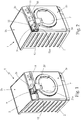
- the detergent drawer 20 is therefore manually movable inside the drawer housing 21 in a preferably substantially horizontally-oriented, displacement direction between a working position (see Figure 2 ) in which the detergent drawer 20 is completely recessed inside the corresponding drawer housing 21 preferably while at same time closing the front entrance or opening 21a of the same drawer housing 21, and a completely extracted position (see Figure 1 ) in which the detergent drawer 20 partly juts out from front wall 2a of casing 2 through the front entrance or opening 21a of the drawer housing 21.
- the drawer housing 21 of detergent drawer 20 is preferably arranged inside casing 2 so as to locate its front entrance or opening 21a immediately beneath the top wall 2b of casing 2, close to the upper right corner of front wall 2a of casing 2; whereas the detergent drawer 20 is preferably movable inside the same drawer housing 21 along a substantially horizontally-oriented, displacement direction which is also locally substantially perpendicular to front wall 2a of casing 2.
- the water supply circuit 22 is structured for selectively spilling/pouring into the detergent drawer 20 a given amount of fresh water arriving from the fresh-water supply circuit 10 preferably in form of a dense shower of water droplets, so as to selectively flush a given quantity of the detergent, softener or other washing agent into the washing tub (not shown).
- the detergent drawer 20 is preferably, though not necessarily, divided into a plurality of detergent compartments 20a (three detergent compartments in the example shown) each of which is manually fillable with a respective washing agent; and the water supply circuit 22 is preferably structured for spilling/pouring the fresh water arriving from the fresh-water supply circuit 10 selectively and alternatively into any one of the detergent compartments 20a of detergent drawer 20, so as to selectively flush the detergent, softener or other washing agent out of the same compartment 20a and down onto the substantially funnel-shaped bottom of the drawer housing 21.
- This mixture of water and detergent, softener or other washing agent afterwards flows into the washing tub (not shown) via the connecting duct branching off from the bottom of drawer housing 21.
- the water supply circuit 22 is preferably structured for selectively spilling/pouring a dense shower of water droplets by gravity directly into any one of the detergent compartments 20a of detergent drawer 20, so as to flush the detergent, softener or other washing agent out of the detergent drawer 20 and down onto the bottom of drawer housing 21.
- the water supply circuit 22 of detergent dispensing assembly 9 preferably comprises an electrically-controlled hydraulic distributor 24 or similar valve assembly, which is arranged/interposed between the fresh-water supply circuit 10 and the various detergent compartments 20a of the detergent drawer 20, i.e. between the outlet of the pipeline 17 and the various detergent compartments 20a of detergent drawer 20, and is structured for selectively and alternatively channelling the fresh water arriving from the fresh-water supply circuit 10 towards the various detergent compartments 20a of detergent drawer 20.
- the water supply circuit 22 preferably also comprises a sprinkler head 25 which is associated to the drawer housing 21 of detergent drawer 20 so as to be located immediately above the detergent drawer 20 when the latter is completely inserted/recessed into the drawer housing 21.
- This sprinkler head 25 is provided with a number (three in the example shown) of shower-making portions/sections 25a each of which is preferably substantially vertically aligned to one or more detergent compartments 20a of detergent drawer 20, and is structured for feeding a dense shower of water droplets by gravity into said detergent compartment/s 20a.
- each shower-making section/portion 25a of sprinkler head 25 is preferably locally vertically aligned to a respective detergent compartment 20a of detergent drawer 20, and is preferably structured for feeding a dense shower of water droplets exclusively into the detergent compartment 20a located immediately beneath.
- the hydraulic distributor 24 is located upstream of the sprinkler head 25, i.e. between the sprinkler head 25 and the fresh-water supply circuit 10, and is structured for channelling the fresh water arriving from the fresh-water supply circuit 10 selectively and alternatively towards the various shower-making sections/portions 25a of the sprinkler head 25.
- the electrically-controlled hydraulic distributor 24 is provided with a water inlet fluidically connected to the fresh-water supply circuit 10, i.e. to pipeline 17, and a number (three in the example shown) of water outlets each fluidically connected to a respective shower-making section/portion 25a of the sprinkler head 25, and it is structured for selectively and alternatively channelling the fresh water arriving from the fresh-water supply circuit 10 to the various shower-making sections/portions 25a of the sprinkler head 25.
- the water-softening agent container 13 is preferably filled with a given amount of ion-exchange resins (not shown) capable to restrain the calcium and/or magnesium ions (Ca++ an Mg++) dissolved in the fresh water flowing across the same water-softening agent container 13, and is located along the fresh-water supply circuit 10 so as to be crossed by the fresh water directed towards the detergent dispensing assembly 9 and/or towards the washing tub (not shown).
- the ion-exchange resins (not shown) stored into the water-softening agent container 13 form the water softening agents of the water softening device 12.
- the water-softening agent container 13, hereinafter also referred to as the resin container 13, is preferably arranged upstream of the hydraulic distributor 24, so as to be crossed by the fresh water flowing from the water mains to the inlet of the water supply circuit 22 of detergent dispensing assembly 9.
- the regeneration-agent reservoir 14 of water softening device 12 instead, consists in a hermetically-closable container 14, i.e. a container closable in a substantially airtight and watertight manner, which is structured for receiving a given amount (for example half a Kilo or one Kilo) of salt (Sodium Chloride) grains or similar regeneration chemical agent, and is provided with an exposed or exposable and hermetically-sealable loading inlet or mouth which is structured for allowing the user to timely load said given amount of consumable salt or other regeneration agent into the same hermetically-closable container 14.
- a hermetically-closable container 14 i.e. a container closable in a substantially airtight and watertight manner, which is structured for receiving a given amount (for example half a Kilo or one Kilo) of salt (Sodium Chloride) grains or similar regeneration chemical agent, and is provided with an exposed or exposable and hermetically-sealable loading inlet or mouth which is structured
- the internal water softening device 12 furthermore comprises:
- the internal water softening device 12 moreover comprises an electrically-controlled, source of pressurized-air 30 which is able to selectively pump/channel a flow of pressurized air or other gas inside the hermetically-closable container 14 so as to form/create, inside the hermetically-closable container 14, a big air volume or bubble which pressurizes the brine contained into the same hermetically-closable container 14.
- the water softening device 12 is preferably also provided with a first water drain line 31 which fluidically connects the resin container 13, i.e. the water-softening agent container 13, to the washing tub (not shown) of the laundry washing machine 1 and is structured for selectively draining the brine or fresh water out of the resin container 13 and channelling said brine or fresh water directly into the washing tub.
- a first water drain line 31 which fluidically connects the resin container 13, i.e. the water-softening agent container 13, to the washing tub (not shown) of the laundry washing machine 1 and is structured for selectively draining the brine or fresh water out of the resin container 13 and channelling said brine or fresh water directly into the washing tub.
- the water drain line 31 is structured for channelling the brine or fresh water stored into the resin container 13 preferably into the drain sump (not shown) that extends downwards form the bottom of the washing tub (not shown), or into the water filtering assembly (not shown) that is interposed between the drain sump (not shown) of the washing tub and the suction of either the water circulating pump (not shown) or the water exhaust pump (not shown), or substantially directly into the water exhaust pump (not shown) which drains the waste water or washing liquor outside of the laundry washing machine 1, or in any case into the waste-water drain line that channels the waste water or washing liquor outside the laundry washing machine 1.
- the water supply circuit 28 of water softening device 12 is preferably structured for being connected to the water mains independently from the fresh-water supply circuit 10, so as to be able to selectively draw a given amount of fresh water from the water mains and channel said fresh water directly into the outside-accessible, hermetically-closable container 14.
- the water supply circuit 28 preferably comprises: a pipeline 32 or the like which connects the hermetically-closable container 14 to the water mains independently from the fresh-water supply circuit 10; and an electrically-controlled on-off valve 33 which is located along pipeline 32, so as to be interposed between the water mains and the hermetically-closable container 14, and is able to control/ regulate the flow of fresh water from the water mains towards the hermetically-closable container 14.
- the electrically-controlled on-off valve 33 is preferably, though not necessarily, attached to the rear wall of casing 2 close to on-off valve 15, and it is directly connected to the hermetically-closable container 14 via the pipeline 32.
- the water supply circuit 28 of water softening device 12 furthermore comprises an auxiliary one-way valve 34 which is located along pipeline 32 preferably immediately downstream of the on-off valve 33, i.e. between the on-off valve 33 and the hermetically-closable container 14, and which is arranged to allow the fresh water to only flow along pipeline 32 from the water mains to the hermetically-closable container 14.
- the electrically-controlled source of pressurized-air 30, in turn, preferably, though not necessarily, comprises an electrically-powered air compressor 35 or similar air-pumping device which has the outlet or delivery in direct communication with the inside of the hermetically-closable container 14 preferably via an air duct 36, so as to be able to selectively pump a flow of pressurized air into the hermetically-closable container 14.
- the pressure of the air channelled into the hermetically-closable container 14 is greater than the ambient pressure.
- the internal water softening device 12 preferably furthermore comprises a water-level sensor (not shown) which is structured for measuring the level of the fresh water and/or brine contained inside the hermetically-closable container 14, and/or a salinity-level sensor (not shown) which is structured for measuring the salinity degree of the brine contained inside the hermetically-closable container 14.
- the internal water softening device 12 may furthermore comprise a pressure sensor (not shown) which is structured for measuring the value of the pressure of the air remained entrapped inside the hermetically-closable container 14.
- a pressure sensor (not shown) which is structured for measuring the value of the pressure of the air remained entrapped inside the hermetically-closable container 14.
- the internal water softening device 12 is preferably also provided with a water-hardness sensor (not shown) which is structured for measuring the hardness degree of the fresh water coming out from the resin container 13, i.e. the water-softening agent container 13, directed towards the detergent dispensing assembly 9.
- a water-hardness sensor (not shown) which is structured for measuring the hardness degree of the fresh water coming out from the resin container 13, i.e. the water-softening agent container 13, directed towards the detergent dispensing assembly 9.
- the water-level sensor and/or the salinity-level sensor and/or the air-pressure sensor and/or the water-hardness sensor is/are able to communicate with an internal electronic central control unit (not shown) which is housed inside the boxlike casing 2 and controls all electrically-operated component parts of the laundry washing machine 1.
- the laundry washing machine 1 is preferably, though not necessarily, also provided with a second water drain line 43 which is structured for selectively rerouting the brine or fresh water coming out from the resin container 13 directed towards the detergent dispensing assembly 9, into the washing tub (not shown) so as to bypass the detergent dispensing assembly 9, or rather at least the detergent container 20, i.e. the detergent drawer 20, of the detergent dispensing assembly 9.
- a second water drain line 43 which is structured for selectively rerouting the brine or fresh water coming out from the resin container 13 directed towards the detergent dispensing assembly 9, into the washing tub (not shown) so as to bypass the detergent dispensing assembly 9, or rather at least the detergent container 20, i.e. the detergent drawer 20, of the detergent dispensing assembly 9.
- the water drain line 43 is structured for channeling the brine or fresh water coming out from the resin container 13 directed towards the detergent dispensing assembly 9, preferably into the drain sump (not shown) that extends downwards form the bottom of washing tub (not shown) of the lundry washing machine 1, or into the water filtering assembly (not shown) that is interposed between the drain sump (not shown) of the washing tub and the suction of the water circulating pump (not shown) and/or of the water exhaust pump (not shown) of the laundry washing machine 1, or in any case into the waste-water drain line that channels the waste water or washing liquor outside the laundry washing machine 1.
- the second water drain line 43 is structured to selectively reroute the brine or fresh water that enters into the detergent dispensing assembly 9 through pipeline 17, directly towards the washing tub (not shown), or towards the drain sump (not shown) that extends downwards form the bottom of the washing tub, or towards the water filtering assembly (not shown) that is interposed between the drain sump (not shown) of the washing tub and the suction of the water circulating pump (not shown) and/or of the water exhaust pump (not shown) of the laundry washing machine 1, so as to bypass solely the detergent container 20, i.e. the detergent drawer 20, of detergent dispensing assembly 9.
- the second water drain line 43 preferably comprises a pipeline 44 or the like which is connected to a specific additional water outlet of the electrically-controlled hydraulic distributor 24 or similar valve assembly of the detergent dispensing assembly 9, and ends directly into the washing tub (not shown), or into the drain sump, or into the water filtering assembly, or into the water exhaust pump; and the electrically-controlled hydraulic distributor 24 is structured to selectively direct/channel directly into pipeline 44 the brine of softened fresh water arriving from resin container 13 via pipeline 17, so as to channel the brine or fresh water arriving from resin container 13 directly into the washing tub (not shown) or into the drain sump (not shown) or into the water filtering assembly (not shown) or into the water exhaust pump (not shown).
- the second water drain line 43 may comprise, immediately upstream of the water supply circuit 22 of detergent dispensing assembly 9, an electrically-controlled three-way valve which has a first outlet connected to the inlet of the water supply circuit 22, i.e. to the hydraulic distributor 24, and a second outlet connected to pipeline 44 of water drain line 43.
- This electrically-controlled three-way valve is structured for selectively and alternatively channelling the fresh water coming out of the resin container 13 either to pipeline 44, or to the inlet of the water supply circuit 22 of detergent dispensing assembly 9, i.e. to the hydraulic distributor 24.
- the second water drain line 43 is structured so as to bypass the whole detergent dispensing assembly 9, and therefore the water supply circuit 22 of detergent dispensing assembly 9 may lack the hydraulic distributor 24.
- the hermetically-closable container 14 of water softening device 12 is preferably dimensioned to contain an amount of brine sufficient for performing several resin regeneration processes.
- the hermetically-closable container 14 is preferably, though not necessarily, located/ incorporated, either in unmovable or in manually detachable manner, into a drawer-like supporting structure 50 which is fitted/inserted in manually extractable manner into a corresponding, substantially completely recessed, drawer housing 51 which, starting from the front wall 2a, extends preferably substantially horizontally inside the casing 2 and communicates with the outside via a front entrance or opening 51a realized on the same front wall 2a of casing 2, so as to be movable in a preferably substantially horizontally-oriented, displacement direction between
- the drawer housing 51 preferably extends substantially horizontally inside the casing 2 while remaining above the washing tub (not shown) and preferably also beside the detergent container 20 of the detergent dispensing assembly 9, and furthermore communicates with the outside via a front entrance or opening 51a which is realized on front wall 2a of casing 2, immediately above the laundry loading/unloading opening on front wall 2a and preferably also beside the exposed or exposable loading inlet of the detergent dispensing assembly 9.
- the drawer housing 51 preferably extends substantially horizontally inside the casing 2 while remaining above the washing tub (not shown) and between the drawer housing 21 of the detergent dispensing assembly 9 and the right sidewall of the casing 2. Furthermore the drawer housing 51 communicates with the outside via a front entrance or opening 51a which is realized on front wall 2a of casing 2 immediately above the laundry loading/ unloading opening and immediately beside the front entrance or opening 21a of the drawer housing 21, opposite to the appliance control panel 11.
- the front entrance or opening 51a of drawer housing 51, the front entrance or opening 21a of drawer housing 21 and the appliance control panel 11 are preferably substantially horizontally aligned on front wall 2a of casing 2, one beside the other substantially immediately underneath the top wall 2b of the same casing 2.
- the hermetically-closable container 14 moreover comprises:
- the water supply circuit 28 is therefore structured to directly communicate with the inside of the storage tank 53 for channelling, on command, a given amount of fresh water from the water mains directly into the storage tank 53, so as to preferably completely dissolve at once the whole salt or other regeneration agents contained into storage tank 53 and form a great amount of brine (i.e. of salt water).
- the air duct 35 is structured to directly communicate with the inside of storage tank 53 for channelling, on command and to the storage tank 53, the pressurized air coming out from the delivery of the air compressor 35.
- the electrically-controlled on-off valve 29, instead, is interposed between the storage tank 53 and the water-softening agent container 13 and is structured to selectively and alternatively put the storage tank 53 in direct communication with the inside of the water-softening agent container 13 for allowing the brine to freely flow from the storage tank 53 to the water-softening agent container 13, or completely watertight seal/isolate the storage tank 53 from the water-softening agent container 13, i.e. from the resin container 13.
- the storage tank 53 is preferably housed/ incorporated into the drawer-like supporting structure 50 so as to be placed almost completely outside of the casing 2 when the drawer-like supporting structure 50 is in the completely extracted position, and is preferably also housed/incorporated into the drawer-like supporting structure 50 in a manually removable manner, so as to be selectively detachable from the drawer-like supporting structure 50 when the drawer-like supporting structure 50 is arranged in the completely extracted position.
- the hermetically-closable container 14 is preferably housed/ incorporated into the drawer-like supporting structure 50 in a manually removable manner, so as to be selectively detachable from the drawer-like supporting structure 50 when the drawer-like supporting structure 50 is arranged in the completely extracted position.
- the hermetically-closable container 14 is housed/recessed into the outer casing 2 in a manually detachable manner.
- the drawer housing 51 of drawer-like supporting structure 50 is preferably provided with a substantially basin-shaped, tank seat 53a which is specifically structured for receiving the storage tank 53 when the drawer-like supporting structure 50 is arranged in the retracted position; and the storage tank 53 is provided with a number self-closing hydraulic and pneumatic connectors 55, 56, 57 which are structured to connect in easily detachable manner the storage tank 53 to, respectively, the water supply circuit 28, the on-off valve 29 and the source of pressurized air 30, preferably during the movement of the drawer-like supporting structure 50 from the extracted to the retracted position.
- the regeneration-agent reservoir 14 is housed into the drawer-like supporting structure 50 in manually removable manner.
- the storage tank 53 is preferably provided with two self-closing hydraulic connectors 55 and 56, and one self-closing pneumatic connector 57.
- Each self-closing hydraulic connector 55, 56 of storage tank 53 is specifically structured to watertight couple in easily detachable manner with a corresponding complementary self-closing hydraulic connector 58, 59 preferably arranged on the drawer-like supporting structure 50; whereas the self-closing pneumatic connector 57 of storage tank 53 is specifically structured to airtight couple in easily detachable manner with a corresponding complementary self-closing pneumatic connector 60 preferably arranged on the drawer-like supporting structure 50.
- the self-closing hydraulic connector 58 of tank seat 53a directly communicates with the water supply circuit 28 of water softening device 12, namely with pipeline 32, and allows, when suitably coupled to the complementary self-closing hydraulic connector 55 of storage tank 53, the fresh water arriving from the water supply circuit 28 to freely flow into storage tank 53, so as to dissolve the salt and produce the brine.
- the self-closing hydraulic connector 59 of tank seat 53a instead, directly communicates with the inlet of the electrically-controlled on-off valve 29 of water softening device 12, and allows, when suitably coupled to the complementary self-closing hydraulic connector 56 of storage tank 53, the brine stored into the storage tank 53 to freely flow out of the storage tank 53 towards the electrically-controlled on-off valve 29 which, in turn, directly communicates with the resin container 13, i.e. with the water-softening agent container 13.
- the self-closing pneumatic connector 60 of tank seat 53a directly communicates with the electrically-controlled source of pressurized air 30 of water softening device 12, namely the air duct 36, and allows, when suitably coupled to the complementary self-closing pneumatic connector 57 of storage tank 53, the pressurized air arriving from the source of pressurized air 30 to freely flow into storage tank 53, so as to form/create the big air volume or bubble which pressurizes the brine contained into the storage tank 53.
- each self-closing hydraulic connector 55, 56 of storage tank 53 is furthermore structured so as to remain closed in watertight manner when uncoupled from the corresponding complementary self-closing hydraulic connector 58, 59 on the drawer-like supporting structure 50; whereas each self-closing hydraulic connector 58, 59 of the drawer-like supporting structure 50 is preferably structured so as to remain closed in watertight manner when uncoupled from the corresponding complementary self-closing hydraulic connector 55, 56 of storage tank 53.
- the self-closing pneumatic connector 57 of storage tank 53 is preferably, though not necessarily, structured so as to remain closed in airtight manner when uncoupled from the corresponding complementary self-closing pneumatic connector 60 of the drawer-like supporting structure 50.
- the self-closing pneumatic connector 60 of the drawer-like supporting structure 50 is preferably, though not necessarily, structured so as to remain closed in airtight manner when uncoupled from the corresponding complementary self-closing pneumatic connector 57 of storage tank 53.
- the self-closing hydraulic and pneumatic connectors 58, 59, 60 are preferably arranged on the back wall of tank seat 53a, so as to couple with the corresponding, complementary self-closing hydraulic and pneumatic connectors 55, 56, 57 of storage tank 53 when the drawer-like supporting structure 50 moves substantially horizontally from the extracted to the retracted position.
- the bottom of tank seat 53a is preferably, though not necessarily, shaped/structured so as to form a catchment basin wherein the fresh water or brine leaking out of the storage tank 53 may accumulate.
- This catchment basin is preferably connected to the bottom of the washing tub (not shown) of the laundry washing machine 1 via a specific water drain line 61 which is structurally similar to the water drain line 31.
- the water drain line 61 may be structured for channelling the brine or fresh water accumulating on the bottom of tank seat 53a preferably into the drain sump (not shown) that extends downwards form the bottom of the washing tub (not shown), or into the water filtering assembly (not shown) that is interposed between the drain sump (not shown) of the washing tub and the suction of the water circulating pump (not shown) and/or of the water exhaust pump (not shown) of the laundry washing machine 1, or in any case into the waste-water drain line that channels the waste water or washing liquor outside the laundry washing machine 1.
- the regeneration-agent reservoir 29 is preferably also provided with a second water-level sensor 62 which is located on the bottom of tank seat 53a and is structured is able to measure the level of the fresh water and/or brine accumulated on the catchment basin formed on the bottom of tank seat 53a, and the electronic central control unit (not shown) of the laundry washing machine 1 activates the water drain line 61 when the level of brine and/or fresh water on the bottom of tank seat 53a exceeds a given threshold value.
- a second water-level sensor 62 which is located on the bottom of tank seat 53a and is structured is able to measure the level of the fresh water and/or brine accumulated on the catchment basin formed on the bottom of tank seat 53a, and the electronic central control unit (not shown) of the laundry washing machine 1 activates the water drain line 61 when the level of brine and/or fresh water on the bottom of tank seat 53a exceeds a given threshold value.
- the laundry washing machine 1 may lack the drawer-like supporting structure 50 and the corresponding drawer hosing 51; and the storage tank 53, i.e. the hermetically-closable container 14, may be structured so as to form a completely stand-alone modular cartridge, which is structured so as to be easily insertable in manually extractable manner into a corresponding, completely recessed tank seat 53a which is preferably realized either on the front wall 2a or on the top wall 2b the casing 2.
- the resin container 13 of water softening device 12 is preferably, though not necessarily, located inside the casing 2 immediately beneath the outside-accessible, hermetically-closable container 14.
- the resin container 13 is preferably attached to the bottom of the drawer housing 51 of the drawer-like supporting structure 50, immediately beside the upper portion of the washing tub (not shown), so as to internally face the front wall 2a of casing 2.
- the resin container 13 is preferably located below the drawer housing 51, within an approximately triangular pocket seat or compartment delimited by the bottom of the drawer housing 51, the front wall 2a of casing 2, the vertical right sidewall of the same casing 2, and the upper portion of the washing tub.
- the resin container 13 preferably, though not necessarily, consists in a completely stand-alone modular cartridge 13 which is provided with mechanical coupling members (not shown) structured for allowing a rigid and stable, though easily releasable, fastening of the stand-alone modular component-part or cartridge 13 directly to the bottom of the drawer housing 51 of drawer-like supporting structure 50, and with hydraulic connectors (not shown) structured for allowing the stable, though easily removable, hydraulic connection of the stand-alone modular cartridge 13 to the fresh water supply circuit 10 and to the outlet of the electrically-controlled on-off valve 29.
- mechanical coupling members not shown
- hydraulic connectors not shown
- a first hydraulic connector (not shown) of the stand-alone modular cartridge 13 is connected to pipeline 16, so as to allow the inflow of the fresh water into the resin container 13;
- a second hydraulic connector (not shown) of the stand-alone modular cartridge 13 is connected to pipeline 17 so as to allow the outflow of the fresh water from the resin container 13 towards the detergent dispensing assembly 9;
- a third hydraulic connector (not shown) of the stand-alone modular cartridge 13 is structured to directly communicate with the outlet of the on-off vale 29 so as to allow the controlled inflow of the brine (i.e. the salt water) into the resin container 13.
- the laundry washing machine 1 is finally provided with a second fresh-water supply circuit 66 which is structured for being connected to the water mains independently from the fresh-water supply circuit 10, and for selectively channelling the fresh water from the water mains to the detergent dispensing assembly 9 and/or directly to the washing tub (not shown), bypassing the water softening device 12.
- a second fresh-water supply circuit 66 which is structured for being connected to the water mains independently from the fresh-water supply circuit 10, and for selectively channelling the fresh water from the water mains to the detergent dispensing assembly 9 and/or directly to the washing tub (not shown), bypassing the water softening device 12.
- the second fresh-water supply circuit 66 connects the water mains directly to the inlet of the water supply circuit 22 of detergent dispensing assembly 9 bypassing the water softening device 12, and is structured so as to selectively channel to the inlet of the water supply circuit 22 a second flow of non-softened fresh water of the water mains.
- the second fresh-water supply circuit 66 is therefore able to channel the fresh water of the water mains directly towards the inlet of water supply circuit 22 independently from the fresh-water supply circuit 10.
- the second fresh-water supply circuit 66 is preferably, though not necessarily, also able to channel the non-softened fresh water of the water mains directly into the washing tub (not shown) via the water drain line 43, thus bypassing all detergent compartments 20a of the detergent drawer 20.
- the second fresh-water supply circuit 66 preferably comprises:
- the second fresh-water supply circuit 66 preferably also comprises a one-way valve 69 which is located downstream of the on-off valve 67, and is arranged so as to allow the fresh water to only flow along the pipeline 68, from the water mains to the inlet of the water supply circuit 22 of detergent dispensing assembly 9, and not vice versa.
- the appliance control panel 11 is furthermore structured so as to allow the user to manually select the desired washing cycle between washing cycles that use softened fresh water, washing cycles that use normal, i.e. non-softened, fresh water, and finally washing cycles that use a mixture of softened and normal, i.e. non-softened, fresh water.
- the softened fresh water of the water mains reaches the detergent dispensing assembly 9 and enters into the electrically-controlled hydraulic distributor 24 of water supply circuit 22.
- the hydraulic distributor 24 then channels the softened fresh water to one or more of the shower-making portions/sections 25a of the sprinkler head 25 for flushing the detergent, softener or other washing agent out of the corresponding detergent compartment 20a of the detergent drawer 20 and sweeping away said detergent, softener or other washing agent down into the washing tub (not shown) via the connecting duct present on the bottom of the drawer housing 21 of detergent drawer 20.
- the electronic central control unit (not shown) of laundry washing machine 1 When determines that the ion-exchange resins inside the resin container 13 are no more able to reduce the hardness degree of the fresh water directed to the washing tub (not shown), the electronic central control unit (not shown) of laundry washing machine 1 performs, preferably immediately before the starting of the rinsing phase of the washing cycle, a regeneration process of the ion-exchange resins stored inside the resin container 13.
- the regeneration process may also take place during the washing phase of the washing cycle, or can take place even when no washing cycle at all is running, preferably on specific request of the user.
- the central control unit of laundry washing machine 1 opens the on-off valve 33 of water supply circuit 28 for a predetermined time interval, so as to fill up with fresh water the hermetically-closable container 14, i.e. the storage tank 53, preferably while also forming/creating/generating at same time an air volume or bubble inside the hermetically-closable container 14.
- the on-off valve 29 is still configured so as to completely watertight seal/isolate the hermetically-closable container 14, i.e. the storage tank 53, from the water-softening agent container 13, the entry of fresh water into the hermetically-closable container 14 naturally stops when the hermetically-closable container 14 is completely full of water and/or the pressure of the air forming the air bubble inside the hermetically-closable container 14, i.e. the storage tank 53, is greater than the ambient pressure and almost equal to the pressure of the fresh water arriving from the water mains.
- the central control unit of laundry washing machine 1 can close the on-off valve 33 of water supply circuit 28 either in advance to the natural stop of the water flow towards the hermetically-closable container 14, so to directly control the level of water/brine contained inside the hermetically-closable container 14, or after the natural stop of the water flow towards the hermetically-closable container 14.
- the brine contained inside the hermetically-closable container 14 will be at a pressure higher than the ambient pressure and lower than that of the fresh water arriving from the water mains.
- the brine contained inside the hermetically-closable container 14 will be at a pressure higher than the ambient pressure and almost equal to that of the fresh water arriving from the water mains.
- brine i.e. of salt water
- the central control unit of laundry washing machine 1 activates the source of pressurized-air 30, i.e. the air compressor 35, so as to pump further pressurized air into the hermetically-closable container 14, i.e. the storage tank 53, so as to further increase the pressure and or volume of the air inside the hermetically-closable container 14, i.e. the pressure or volume of the air forming the air bubble inside the hermetically-closable container 14.
- This pressurized air pressurizes the brine contained inside the hermetically-closable container 14 at a pressure value greater than the ambient pressure and preferably, though not necessarily, also greater than that of the fresh water arriving from the water mains.
- the central control unit of laundry washing machine 1 may activate the source of pressurized-air 30, i.e. the air compressor 35, so to create from zero the air volume or bubble of pressurized air into the hermetically-closable container 14.
- the hermetically-closable container 14 Since the hermetically-closable container 14 is substantially airtight and watertight, the brine contained into the hermetically-closable container 14 remains pressurized at a pressure greater than the ambient pressure, until a resin regeneration process is requested to take place and the central control unit of the laundry washing machine 1 opens the on-off valve 29.
- the central control unit of laundry washing machine 1 closes the on-off valve 15 of the fresh-water supply circuit 10 to stop the flow of fresh water across the resin container 13, and preferably also arranges the hydraulic distributor 24 of detergent dispensing assembly 9 so as to channel the fresh water arriving from the resin container 13 directly into the water drain line 43.
- the central control unit of laundry washing machine 1 opens the on-off valve 29 to allow the brine to flow from the regeneration-agent reservoir 14, i.e. the hermetically-closable container 14, to the resin container 13.
- the movement of the brine from the regeneration-agent reservoir 14, i.e. the hermetically-closable container 14, to the resin container 13 is supported by the pressurized air forming the air volume or bubble inside the hermetically-closable container 14, thus the resin container 13 may be located above the regeneration-agent reservoir 14, i.e. the hermetically-closable container 14.
- the outflow of the brine from the hermetically-closable container 14 causes a progressive drop of the pressure of the air entrapped into the hermetically-closable container 14, i.e. the storage tank 53.
- the central control unit of laundry washing machine 1 activates the again the source of pressurized-air 30, i.e. the air compressor 35, so as to pump further pressurized air into the hermetically-closable container 14, i.e. the storage tank 53, thus increasing again the pressure of the air entrapped into the hermetically-closable container 14.
- the central control unit of the laundry washing machine 1 temporarily opens again the on-off valve 33 of water supply circuit 28 to channel some more fresh water into the hermetically-closable container 14 and increase the quantity of brine contained into the hermetically-closable container 14, i.e. the storage tank 53.
- the central control unit of laundry washing machine 1 closes the on-off valve 29, so as to watertight isolate the resin container 13 from the regeneration-agent reservoir 14, and then keeps the brine inside the resin container 13 for a predetermined time interval generally sufficient to allow the brine to remove from the ion-exchange resins the calcium and magnesium ions previously combined/fixed to said resins.
- the central control unit of laundry washing machine 1 opens again the on-off valve 15 of fresh-water supply circuit 10, so that the pressurized fresh water of the water mains pushes the brine out of the resin container 13 and into the pipeline 17 which channels the brine towards the hydraulic distributor 24 which, in turn, directs/channels said fresh water directly into the second water drain line 43.
- the central control unit of laundry washing machine 1 may open the on-off valve 38 of the water drain line 31 so to drain the brine out of the resin container 13 through the water drain line 31.
- the brine stored in the resin container 13 flows directly into the washing tub, or into the drain sump, or into the water filtering assembly, or into the water exhaust pump, via the water drain line 31 and/or via the water drain line 43.
- the central control unit of the laundry washing machine 1 activates the water exhaust pump so to discharge the brine out of the laundry washing machine 1 preferably together with the washing or rinsing water already stored on the bottom of the washing tub (not shown), and continues the washing cycle.
- the second fresh-water supply circuit 66 can channel the fresh water of the water mains towards the inlet of water supply circuit 22 bypassing the water softening device 12, so to channel the non-softened fresh water of the water mains directly towards the inlet of the water supply circuit 22 of detergent dispensing assembly 9.
- the water supply circuit 22 of detergent dispensing assembly 9 therefore can channel towards any one of the detergent compartments 20a of detergent drawer 20, or towards the second water drain line 43 if connected to the hydraulic distributor 24, either softened, non-softened (i.e. normal) fresh water of the water mains or a mixture thereof.
- the laundry washing machine 1 is therefore able to use, during each stage of the washing cycle, either softened or non-softened fresh water of the water mains or a mixture thereof.
- the second fresh-water supply circuit 66 in fact, can channel non-softened fresh water to the inlet of the water supply circuit 22 of detergent dispensing assembly 9 independently from the fresh-water supply circuit 10, thus also at the same time of the fresh-water supply circuit 10.
- the internal water softening device 12 may lack the electrically-controlled source of pressurized-air 30, i.e. the air compressor 35, and use the water supply circuit 28 to control the level of the liquid contained into the hermetically-closable container 14, so as to regulate the pressure of the air forming the air volume or bubble.
- the central control unit of laundry washing machine 1 opens the on-off valve 33 of water supply circuit 28 for a predetermined time interval, so as to fill with fresh water the hermetically-closable container 14, i.e. the storage tank 53, and also form/create/generate at same time a relatively big air volume or bubble inside the hermetically-closable container 14 ( Figure 9b ).
- the on-off valve 29 is still configured so as to completely watertight seal/isolate the hermetically-closable container 14, i.e. the storage tank 53, from the water-softening agent container 13, the entry of fresh water into the hermetically-closable container 14 naturally stops when the pressure of the air forming the air bubble inside the hermetically-closable container 14, i.e. inside the storage tank 53, is greater than the ambient pressure and preferably almost equal to the pressure of the fresh water arriving from the water mains.
- the central control unit of laundry washing machine 1 can close the on-off valve 33 of water supply circuit 28 either in advance to the natural stop of the water flow towards the hermetically-closable container 14, so to directly control the level of water/brine contained inside the hermetically-closable container 14, or after the natural stop of the water flow towards the hermetically-closable container 14.
- the brine contained inside the hermetically-closable container 14 will be at a pressure higher than the ambient pressure and lower than that of the fresh water arriving from the water mains.
- the brine contained inside the hermetically-closable container 14 will be at a pressure higher than the ambient pressure and almost equal to that of the fresh water arriving from the water mains.
- This great amount of brine remains inside the hermetically-closable container 14 at a pressure higher than the ambient pressure until a resin regeneration process is requested to take place.
- the air remained entrapped into the hermetically-closable container 14, i.e. the storage tank 53, is compressed up to water-mains pressure by the pressurized fresh water that the water supply circuit 28 channels into the hermetically-closable container 14.
- the central control unit of the laundry washing machine 1 temporarily closes the on-off valve 29 and opens the on-off valve 33 of water supply circuit 28 so to channel some more fresh water into the hermetically-closable container 14 and increase the level of water/brine contained into the hermetically-closable container 14, i.e. the storage tank 53.
- the central control unit of laundry washing machine 1 temporarily closes the on-off valve 29 and opens the on-off valve 33 of water supply circuit 28 so as to channel some more fresh water into the hermetically-closable container 14, i.e. the storage tank 53, thus increasing again the volume/level of water/brine into the hermetically-closable container 14 and consequently recompress the air entrapped into the hermetically-closable container 14, i.e. the storage tank 53.
- the central control unit of laundry washing machine 1 closes the on-off valve 33 of water supply circuit 28 and opens again the on-off valve 29 to continue transferring the brine from the hermetically-closable container 14, i.e. from the storage tank 53, to the water-softening agent container 13.
- the central control unit of laundry washing machine 1 may open the on-off valve 33 of water supply circuit 28 and the on-off valve 29 at same time, so as to keep substantially constant the volume of liquid into the hermetically-closable container 14.
- the movement of the brine from the hermetically-closable container 14 to the resin container 13 is supported by a substantially equivalent amount of fresh water arriving into the hermetically-closable container 14 via the water supply circuit 28.
- the water supply circuit 28 preferably branches off from the fresh-water supply circuit 10 downstream of resin container 13, so as to selectively channel into the regeneration-agent reservoir 29 the softened fresh water coming out of resin container 13.
- the water supply circuit 28 lacks the on-off valve 33 and instead comprises an electrically-controlled three-way valve 70 which is arranged along the fresh-water supply circuit 10, downstream of resin container 13, i.e. along the pipeline 17 connecting the outlet of resin container 13 to the inlet of the water supply circuit 22 of detergent dispensing assembly 9.
- the pipeline 32 of water supply circuit 28 is now connected to the three-way valve 70, and the electrically-controlled three-way valve 70 is structured for selectively and alternatively channelling the fresh water coming out of the resin container 13, into the hermetically-closable container 14, i.e. into the storage tank 53, for producing the brine, or to the inlet of the water supply circuit 22 of detergent dispensing assembly 9 for performing the washing cycle.
- the electronic central control unit of laundry washing machine 1 sets the three-way valve 70 of water supply circuit 28 so as to put the outlet of resin container 13 in direct communication with the inside of the hermetically-closable container 14, i.e. of the storage tank 53, and afterwards opens the on-off valve 15 of the fresh-water supply circuit 10 for enough time to channel into the hermetically-closable container 14 the fresh water necessary to dissolve the salt contained therein, and form an amount of brine sufficient to perform several resin regeneration processes.
- This fresh water obviously flows across the resin container 13 before reaching the hermetically-closable container 14.
- the central control unit of laundry washing machine 1 sets the three-way valve 70 so as to put again the outlet of resin container 13 in direct communication with the detergent dispensing assembly 9.
- the brine contained into the hermetically-closable container 14 remains pressurized at a pressure greater than the ambient pressure, until a resin regeneration process is requested to take place and the central control unit of the laundry washing machine 1 opens the on-off valve 29.
- the electronic central control unit of the laundry washing machine 1 may be programmed to regenerate the ion-exchange resins stored in the resin container 13 after a given number of washing cycles.
- the water-hardness sensor is no more necessary.
- the number of washing cycles to wait for performing a resin regeneration process may be decided by the user on the basis of an alleged hardness degree of the fresh water coming out from the water mains.
- the second fresh-water supply circuit 66 bypassing the internal water softening device 12 allows to improve the working flexibility of the laundry washing machine 1.
- the laundry washing machine 1 can use normal fresh water, thus lengthening the time between the regenerations of the ion-exchange resins.
- the appliance control panel 11 may be structured so as to allow the user to manually select washing cycles that use softened fresh water, washing cycles that use normal, i.e. non-softened, fresh water, and finally washing cycles that use a mixture of softened and normal, i.e. non-softened, fresh water.
- the appliance control panel 11 is arranged substantially immediately underneath the top wall 2b of casing 2, almost astride of the vertical center-plane of the casing 2, so as to be substantially vertically aligned to the laundry loading/unloading opening realized on front wall 2a of casing 2; and the drawer-like supporting structure 50 carrying the hermetically-closable container 14 is fitted/inserted in manually extractable manner into a corresponding, substantially completely recessed, drawer housing 51 which is located immediately beside the appliance control panel 11, substantially at the upper left corner of front wall 2a.
- the appliance control panel 11 is therefore laterally flanked, on opposite sides, by the exposed or exposable loading inlet or mouth of the detergent dispensing assembly 9, i.e. by the detergent drawer 20, and by the drawer-like supporting structure 50 that supports the hermetically-closable container 14.
- the hermetically-closable container 14 preferably comprises a storage tank 53 which is structured for being manually fillable with a given quantity of consumable salt or other regeneration agent, a manually-removable sealing cap 54 which is structured to hermetically closed the storage tank 53.
- the storage tank 53 is preferably housed/located, either in unmovable or in manually detachable manner, into the drawer-like supporting structure 50 so as to be freely accessible by the user when the drawer-like supporting structure 50 is in the extracted position, and to be hidden and inaccessible by the user when the drawer-like supporting structure 50 is arranged in the retracted position.
- the appliance control panel 11 is located/arranged on front of a drawer-like supporting structure 150 which is fitted/inserted in manually extractable manner into the front wall 2a of casing 2, preferably between the laundry loading/unloading opening on front wall 2a and the top wall of casing 2, so as to be movable in a preferably substantially horizontally-oriented, displacement direction d between
- the hermetically-closable container 14 of water softening device 12 is located/incorporated into the drawer-like supporting structure 150, so as to be hidden into the casing 2 and inaccessible to the user when the drawer-like supporting structure 150 is arranged in the retracted position, and so as to be freely accessible by the user when the drawer-like supporting structure 150 is arranged in the completely extracted position (see Figures 7 ).
- the hermetically-closable container 14 preferably comprises: a storage tank 53 which is structured for being manually fillable with a given quantity of consumable salt or other regeneration agent, and is housed/located, into the drawer-like supporting structure 50, either in unmovable or in manually detachable manner; and a manually-removable sealing cap 54 which is structured to hermetically closed the storage tank 53.
- the hermetically-closable container 14 of water softening device 12 is recessed/located immediately underneath the worktop 2b of casing 2, preferably substantially immediately behind the appliance control panel 11, and is moreover preferably freely accessible by the user through a manual-operated trapdoor 100 realized on worktop 2b of casing 2.
- the hermetically-closable container 14 preferably comprises: a storage tank 53 which is structured for being manually fillable with a given quantity of consumable salt or other regeneration agent, and is recessed/ located underneath the top wall 2b of casing 2, either in unmovable or in manually detachable manner; and a manually-removable sealing cap 54 which is structured to hermetically closed the storage tank 53.
Landscapes
- Engineering & Computer Science (AREA)
- Textile Engineering (AREA)
- Detail Structures Of Washing Machines And Dryers (AREA)
Claims (18)
- Machine à laver le linge (1) comprenant un boîtier extérieur (2) et, à l'intérieur dudit boîtier extérieur (2), un bac de lavage, un tambour rotatif logé de manière axialement rotative à l'intérieur du bac de lavage et structuré de manière à recevoir le linge à laver, un ensemble de distribution de détergent (9) qui est structuré de manière à fournir du détergent dans le bac de lavage, un circuit d'alimentation en eau fraîche (10) qui est structuré de manière à canaliser de manière sélective un flux d'eau fraîche provenant de la canalisation d'eau principale vers l'ensemble de distribution de détergent (9) et/ou vers le bac de lavage, et un dispositif d'adoucissement de l'eau (12) qui est disposé/situé le long du circuit d'alimentation en eau fraîche (10) et qui est structuré de manière à réduire le degré de dureté de l'eau fraîche canalisée vers l'ensemble de distribution de détergent (9) et/ou vers le bac de lavage ;
le dispositif d'adoucissement de l'eau (12) comprenant à son tour un récipient d'agent adoucisseur d'eau (13) qui est disposé/situé le long du circuit d'alimentation en eau fraîche (10) et qui est rempli d'un agent adoucisseur d'eau apte à réduire le degré de dureté de l'eau fraîche s'écoulant à travers ledit récipient d'agent adoucisseur d'eau (13) ; un réservoir d'agent de régénération (14) qui est connectée fluidiquement au récipient d'agent adoucisseur d'eau (13) et qui est structuré de manière à recevoir un agent de régénération consommable pour effectuer une régénération de la fonction d'adoucissement de l'eau de l'agent adoucisseur d'eau stocké dans le récipient d'agent adoucisseur d'eau (13) ; et un circuit d'alimentation en eau (28) qui est structuré de manière à canaliser de l'eau fraîche dans le réservoir d'agent de régénération (14) de manière à au moins en partie dissoudre les agents de régénération stockés dans celui-ci pour former de la saumure ;
la machine à laver le linge (1) étant caractérisée en ce que le réservoir d'agent de régénération (14) comprend un récipient pouvant être fermé hermétiquement (14) qui est structuré de manière à recevoir une quantité donnée d'agent de régénération consommable ; et en ce que le dispositif d'adoucissement de l'eau (12) comprend en outre des moyens de pressurisation à commande électrique (28, 30) qui sont structurés de manière à former, dans ledit récipient pouvant être fermé hermétiquement (14), un volume d'air ou une bulle d'air sous pression qui pressurise la saumure contenue dans le récipient pouvant être fermé hermétiquement (14). - Machine à laver le linge selon la revendication 1, caractérisée en ce que le récipient pouvant être fermé hermétiquement (14) est pourvu d'une entrée ou d'une embouchure de chargement exposée ou pouvant être exposée et pouvant être fermée hermétiquement, qui est structurée de manière à permettre à l'utilisateur de charger l'agent de régénération consommable dans ledit récipient pouvant être fermé hermétiquement (14).
- Machine à laver le linge selon la revendication 1 ou 2, caractérisée en ce que les moyens de pressurisation (28, 30) comprennent le circuit d'alimentation en eau (28) du dispositif d'adoucissement de l'eau (12).
- Machine à laver le linge selon la revendication 3, caractérisée en ce que le circuit d'alimentation en eau (28) du dispositif d'adoucissement de l'eau (12) est apte à commander le niveau du liquide contenu dans le récipient pouvant être fermé hermétiquement (14), de manière à réguler la pression de l'air formant ledit volume d'air ou ladite bulle d'air.
- Machine à laver le linge selon la revendication 3 ou 4, caractérisée en ce que le circuit d'alimentation en eau (28) du dispositif d'adoucissement de l'eau (12) comprend un ensemble de soupape (33, 70) qui est interposé entre la canalisation d'eau principale et le récipient pouvant être fermé hermétiquement (14), et qui est apte à commander/réguler le flux d'eau fraîche vers le récipient pouvant être fermé hermétiquement (14).
- Machine à laver le linge selon la revendication 1, 2 ou 3, caractérisée en ce que les moyens de pressurisation (28, 30) comprennent une source d'air sous pression (30) à commande électrique qui est apte à pomper/canaliser de manière sélective un flux d'air sous pression ou d'un autre gaz à l'intérieur du récipient pouvant être fermé hermétiquement (14).
- Machine à laver le linge selon la revendication 6, caractérisée en ce que la source d'air sous pression (30) à commande électrique comprend un dispositif de pompage d'air à commande électrique (35) qui présente la sortie ou la distribution en communication directe avec l'intérieur du récipient pouvant être fermé hermétiquement (14) de manière à pouvoir pomper de manière sélective un flux d'air sous pression dans ledit récipient pouvant être fermé hermétiquement (14).
- Machine à laver le linge selon l'une quelconque des revendications précédentes, caractérisée en ce que le dispositif d'adoucissement de l'eau (12) comprend en outre une soupape marche-arrêt à commande électrique (29) qui est interposée entre le récipient pouvant être fermé hermétiquement (14) et le récipient d'agent adoucisseur d'eau (13), et qui est structurée de manière à mettre sélectivement et alternativement le récipient pouvant être fermé hermétiquement (14) en communication directe avec l'intérieur du récipient d'agent adoucisseur d'eau (13), ou à sceller/isoler de manière complètement étanche à l'eau le récipient pouvant être fermé hermétiquement (14) par rapport au récipient d'agent adoucisseur d'eau (13).
- Machine à laver le linge selon l'une quelconque des revendications précédentes, caractérisée en ce que le dispositif d'adoucissement de l'eau (12) comprend en outre un capteur de niveau d'eau qui est structuré de manière à mesurer le niveau de l'eau fraîche et/ou de la saumure contenue à l'intérieur du récipient pouvant être fermé hermétiquement (14), et/ou un capteur de niveau de salinité qui est structuré de manière à mesurer le degré de salinité de la saumure contenue à l'intérieur du récipient pouvant être fermé hermétiquement (14), et/ou un capteur de pression qui est structuré de manière à mesurer la valeur de la pression de l'air restant piégé à l'intérieur du récipient pouvant être fermé hermétiquement (14).
- Machine à laver le linge selon l'une quelconque des revendications précédentes, caractérisée en ce que le récipient pouvant être fermé hermétiquement (14) est logé/reçu à l'intérieur du boîtier extérieur (2) de manière à pouvoir être détaché manuellement.
- Machine à laver le linge selon l'une quelconque des revendications précédentes, caractérisée en ce que le récipient pouvant être fermé hermétiquement (14) comprend un réservoir de stockage (53) qui est structuré de manière à pouvoir être rempli manuellement avec une quantité donnée dudit agent de régénération consommable, et un capuchon de fermeture étanche pouvant être enlevé manuellement (54) qui est structuré de manière à fermer hermétiquement le réservoir de stockage (53).
- Machine à laver le linge selon la revendication 11, caractérisée en ce que le réservoir de stockage (53) est pourvu d'un certain nombre de connecteurs hydrauliques à fermeture automatique (55, 56) qui sont structurés de manière à s'accoupler de manière détachable avec des connecteurs hydrauliques complémentaires correspondants à fermeture automatique (58, 59) disposés à l'intérieur du boîtier (2), de manière à mettre de manière sélective le réservoir de stockage (53) en communication avec le circuit d'alimentation en eau (28) du dispositif d'adoucissement de l'eau (12) et avec la soupape marche-arrêt (29) du dispositif d'adoucissement de l'eau (12).
- Machine à laver le linge selon la revendication 11 ou 12, caractérisée en ce que le réservoir de stockage (53) est pourvu d'un connecteur pneumatique à fermeture automatique (57), qui est structuré de manière à s'accoupler de manière détachable avec un connecteur pneumatique complémentaire correspondant à fermeture automatique (60) disposé à l'intérieur du boîtier (2), de manière à mettre de manière sélective le réservoir de stockage (53) en communication avec lesdits moyens de pressurisation (28, 30).
- Procédé de fonctionnement d'une machine à laver le linge (1) ayant un dispositif d'adoucissement de l'eau interne (12) qui comprend : un récipient d'agent adoucisseur d'eau (13) qui est parcouru par l'eau fraîche s'écoulant le long du circuit d'alimentation en eau fraîche (10), et qui est rempli d'un agent adoucisseur d'eau apte à réduire le degré de dureté de l'eau fraîche s'écoulant à travers ledit récipient d'agent adoucisseur d'eau (13), et un réservoir d'agent de régénération (14) comportant un récipient pouvant être fermé hermétiquement (14) qui est connecté fluidiquement au récipient d'agent adoucisseur d'eau (13) et qui est structuré de manière à recevoir un agent de régénération consommable pour effectuer une régénération de la fonction d'adoucissement de l'eau de l'agent adoucisseur d'eau stocké dans le récipient d'agent adoucisseur d'eau (13) ; le procédé de fonctionnement de la machine à laver le linge (1) étant caractérisé en ce qu'il comprend l'étape consistant à canaliser une quantité donnée d'eau fraîche dans le réservoir d'agent de régénération (14) de manière à dissoudre au moins en partie les agents de régénération stockés dans celui-ci pour former de la saumure ; et l'étape consistant à générer à l'intérieur du réservoir d'agent de régénération (14) un volume d'air ou une bulle d'air sous pression qui pressurise la saumure contenue dans le récipient pouvant être fermé hermétiquement (14).
- Procédé de fonctionnement selon la revendication 14, caractérisé en ce que l'étape consistant à créer ledit volume d'air ou ladite bulle d'air à l'intérieur du réservoir d'agent de régénération (14) comprend l'étape consistant à pomper/canaliser un flux d'air sous pression ou d'un autre gaz à l'intérieur du récipient pouvant être fermé hermétiquement (14) après avoir canalisé l'eau fraîche dans ledit réservoir d'agent de régénération (14).
- Procédé de fonctionnement selon la revendication 14, caractérisé en ce que l'étape consistant à créer ledit volume d'air ou ladite bulle d'air à l'intérieur du réservoir d'agent de régénération (14) comprend l'étape consistant à canaliser l'eau fraîche dans le réservoir d'agent de régénération (14) de manière à réguler le niveau du liquide contenu dans le récipient pouvant être fermé hermétiquement (14).
- Procédé de fonctionnement selon la revendication 14, 15 ou 16, caractérisé en ce qu'un ensemble de soupape (29) est interposé entre le récipient pouvant être fermé hermétiquement (14) et le récipient d'agent adoucisseur d'eau (13) ; ledit ensemble de soupape (29) étant structuré de manière à sélectivement sceller/isoler de manière étanche à l'eau le récipient pouvant être fermé hermétiquement (14) par rapport au récipient d'agent adoucisseur d'eau (13), le procédé de fonctionnement comprenant l'étape consistant à ouvrir le ledit ensemble de soupape (29) pour permettre à la saumure de s'écouler depuis le récipient pouvant être fermé hermétiquement (14) dans le récipient d'agent adoucisseur d'eau (13) après la création du volume d'air ou de la bulle d'air dans le récipient pouvant être fermé hermétiquement (14).
- Procédé de fonctionnement selon la revendication 17, caractérisé en ce qu'il comprend également l'étape consistant à canaliser de l'eau fraîche supplémentaire dans le réservoir d'agent de régénération (14) lorsque l'ensemble de soupape (29) est ouvert pour forcer la saumure à s'écouler depuis le récipient pouvant être fermé hermétiquement (14) dans le récipient d'agent adoucisseur d'eau (13).
Applications Claiming Priority (1)
| Application Number | Priority Date | Filing Date | Title |
|---|---|---|---|
| PCT/EP2013/052299 WO2014121823A1 (fr) | 2013-02-06 | 2013-02-06 | Machine à laver le linge et procédé de fonctionnement s'y rapportant |
Publications (2)
| Publication Number | Publication Date |
|---|---|
| EP2971323A1 EP2971323A1 (fr) | 2016-01-20 |
| EP2971323B1 true EP2971323B1 (fr) | 2017-06-21 |
Family
ID=47710120
Family Applications (1)
| Application Number | Title | Priority Date | Filing Date |
|---|---|---|---|
| EP13703774.3A Active EP2971323B1 (fr) | 2013-02-06 | 2013-02-06 | Machine à laver le linge et procédé de fonctionnement s'y rapportant |
Country Status (3)
| Country | Link |
|---|---|
| US (1) | US20150368848A1 (fr) |
| EP (1) | EP2971323B1 (fr) |
| WO (1) | WO2014121823A1 (fr) |
Families Citing this family (10)
| Publication number | Priority date | Publication date | Assignee | Title |
|---|---|---|---|---|
| WO2015074688A1 (fr) * | 2013-11-20 | 2015-05-28 | Electrolux Appliances Aktiebolag | Machine à laver le linge à tiroir à détergent comprenant un tableau de commande |
| US10494751B2 (en) | 2013-12-30 | 2019-12-03 | Electrolux Appliances Aktiebolag | Laundry washing machine with water softening system and method for controlling a laundry washing machine |
| AU2013409580B2 (en) | 2013-12-30 | 2019-01-17 | Electrolux Appliances Aktiebolag | Laundry washing machine with water softening system and method for controlling a laundry washing machine |
| AU2013409579B2 (en) | 2013-12-30 | 2019-09-12 | Electrolux Appliances Aktiebolag | Laundry washing machine and method for controlling a laundry washing machine |
| US10563339B2 (en) * | 2013-12-30 | 2020-02-18 | Electrolux Appliances Aktiebolag | Laundry washing machine and method for controlling a laundry washing machine |
| USD777386S1 (en) * | 2014-06-16 | 2017-01-24 | Electrolux Appliances Aktiebolag | Door for a laundry appliance |
| PL3234253T3 (pl) * | 2014-12-18 | 2022-12-27 | Electrolux Appliances Aktiebolag | Pralka do prania |
| USD775771S1 (en) * | 2015-03-18 | 2017-01-03 | Samsung Electronics Co., Ltd. | Washing machine |
| KR102512289B1 (ko) | 2016-05-30 | 2023-03-22 | 엘지전자 주식회사 | 의류처리장치 |
| US11485647B2 (en) * | 2019-05-23 | 2022-11-01 | Bsh Home Appliances Corporation | Changeable water filter in combination with a mixing valve for pretreatment of water in a home appliance and method of pretreating water |
Family Cites Families (6)
| Publication number | Priority date | Publication date | Assignee | Title |
|---|---|---|---|---|
| DE1225569B (de) * | 1961-05-20 | 1966-09-22 | Paul Dosch | Verfahren und Vorrichtung zum Wasserenthaerten fuer Wasch- und Geschirrspuelmaschinen |
| IT1309792B1 (it) * | 1999-04-22 | 2002-01-30 | Eltek Spa | Elettrodomestico utilizzante acqua, in particolare una macchinadi lavaggio, con dispositivo perfezionato per l'abbattimento |
| JP2001087592A (ja) * | 1999-09-20 | 2001-04-03 | Hitachi Ltd | ドラム式洗濯機 |
| US20060117811A1 (en) * | 2004-12-06 | 2006-06-08 | Kinnetz Roger E | Liquid detergent dispensing system for automatic washer |
| US20060191299A1 (en) * | 2004-12-15 | 2006-08-31 | Andrew Tobias | Garment steamer |
| US8566990B2 (en) * | 2006-07-10 | 2013-10-29 | Lg Electronics Inc. | Laundry machine and controlling method thereof |
-
2013
- 2013-02-06 EP EP13703774.3A patent/EP2971323B1/fr active Active
- 2013-02-06 WO PCT/EP2013/052299 patent/WO2014121823A1/fr not_active Ceased
- 2013-02-06 US US14/766,005 patent/US20150368848A1/en not_active Abandoned
Also Published As
| Publication number | Publication date |
|---|---|
| US20150368848A1 (en) | 2015-12-24 |
| EP2971323A1 (fr) | 2016-01-20 |
| WO2014121823A1 (fr) | 2014-08-14 |
Similar Documents
| Publication | Publication Date | Title |
|---|---|---|
| EP2971323B1 (fr) | Machine à laver le linge et procédé de fonctionnement s'y rapportant | |
| US9828720B2 (en) | Laundry washing machine with a water softening device | |
| US9903062B2 (en) | Laundry washing machine | |
| US9903064B2 (en) | Laundry washing machine | |
| US9624618B2 (en) | Laundry washing machine | |
| US9637856B2 (en) | Laundry washing machine | |
| EP2867398B1 (fr) | Machine à laver le linge | |
| US9970147B2 (en) | Laundry washing machine | |
| EP2954112B1 (fr) | Machine à laver le linge comprenant un dispositif adoucisseur d'eau | |
| EP2841636B1 (fr) | Machine à laver le linge | |
| WO2014121830A1 (fr) | Machine à laver le linge |
Legal Events
| Date | Code | Title | Description |
|---|---|---|---|
| PUAI | Public reference made under article 153(3) epc to a published international application that has entered the european phase |
Free format text: ORIGINAL CODE: 0009012 |
|
| 17P | Request for examination filed |
Effective date: 20150910 |
|
| AK | Designated contracting states |
Kind code of ref document: A1 Designated state(s): AL AT BE BG CH CY CZ DE DK EE ES FI FR GB GR HR HU IE IS IT LI LT LU LV MC MK MT NL NO PL PT RO RS SE SI SK SM TR |
|
| AX | Request for extension of the european patent |
Extension state: BA ME |
|
| DAX | Request for extension of the european patent (deleted) | ||
| GRAP | Despatch of communication of intention to grant a patent |
Free format text: ORIGINAL CODE: EPIDOSNIGR1 |
|
| INTG | Intention to grant announced |
Effective date: 20170130 |
|
| GRAS | Grant fee paid |
Free format text: ORIGINAL CODE: EPIDOSNIGR3 |
|
| GRAA | (expected) grant |
Free format text: ORIGINAL CODE: 0009210 |
|
| AK | Designated contracting states |
Kind code of ref document: B1 Designated state(s): AL AT BE BG CH CY CZ DE DK EE ES FI FR GB GR HR HU IE IS IT LI LT LU LV MC MK MT NL NO PL PT RO RS SE SI SK SM TR |
|
| REG | Reference to a national code |
Ref country code: GB Ref legal event code: FG4D |
|
| REG | Reference to a national code |
Ref country code: CH Ref legal event code: EP |
|
| REG | Reference to a national code |
Ref country code: IE Ref legal event code: FG4D |
|
| REG | Reference to a national code |
Ref country code: AT Ref legal event code: REF Ref document number: 903041 Country of ref document: AT Kind code of ref document: T Effective date: 20170715 |
|
| REG | Reference to a national code |
Ref country code: DE Ref legal event code: R096 Ref document number: 602013022516 Country of ref document: DE |
|
| REG | Reference to a national code |
Ref country code: NL Ref legal event code: MP Effective date: 20170621 |
|
| PG25 | Lapsed in a contracting state [announced via postgrant information from national office to epo] |
Ref country code: LT Free format text: LAPSE BECAUSE OF FAILURE TO SUBMIT A TRANSLATION OF THE DESCRIPTION OR TO PAY THE FEE WITHIN THE PRESCRIBED TIME-LIMIT Effective date: 20170621 Ref country code: FI Free format text: LAPSE BECAUSE OF FAILURE TO SUBMIT A TRANSLATION OF THE DESCRIPTION OR TO PAY THE FEE WITHIN THE PRESCRIBED TIME-LIMIT Effective date: 20170621 Ref country code: NO Free format text: LAPSE BECAUSE OF FAILURE TO SUBMIT A TRANSLATION OF THE DESCRIPTION OR TO PAY THE FEE WITHIN THE PRESCRIBED TIME-LIMIT Effective date: 20170921 Ref country code: HR Free format text: LAPSE BECAUSE OF FAILURE TO SUBMIT A TRANSLATION OF THE DESCRIPTION OR TO PAY THE FEE WITHIN THE PRESCRIBED TIME-LIMIT Effective date: 20170621 Ref country code: GR Free format text: LAPSE BECAUSE OF FAILURE TO SUBMIT A TRANSLATION OF THE DESCRIPTION OR TO PAY THE FEE WITHIN THE PRESCRIBED TIME-LIMIT Effective date: 20170922 |
|
| REG | Reference to a national code |
Ref country code: LT Ref legal event code: MG4D |
|
| REG | Reference to a national code |
Ref country code: AT Ref legal event code: MK05 Ref document number: 903041 Country of ref document: AT Kind code of ref document: T Effective date: 20170621 |
|
| PG25 | Lapsed in a contracting state [announced via postgrant information from national office to epo] |
Ref country code: BG Free format text: LAPSE BECAUSE OF FAILURE TO SUBMIT A TRANSLATION OF THE DESCRIPTION OR TO PAY THE FEE WITHIN THE PRESCRIBED TIME-LIMIT Effective date: 20170921 Ref country code: RS Free format text: LAPSE BECAUSE OF FAILURE TO SUBMIT A TRANSLATION OF THE DESCRIPTION OR TO PAY THE FEE WITHIN THE PRESCRIBED TIME-LIMIT Effective date: 20170621 Ref country code: NL Free format text: LAPSE BECAUSE OF FAILURE TO SUBMIT A TRANSLATION OF THE DESCRIPTION OR TO PAY THE FEE WITHIN THE PRESCRIBED TIME-LIMIT Effective date: 20170621 Ref country code: LV Free format text: LAPSE BECAUSE OF FAILURE TO SUBMIT A TRANSLATION OF THE DESCRIPTION OR TO PAY THE FEE WITHIN THE PRESCRIBED TIME-LIMIT Effective date: 20170621 Ref country code: SE Free format text: LAPSE BECAUSE OF FAILURE TO SUBMIT A TRANSLATION OF THE DESCRIPTION OR TO PAY THE FEE WITHIN THE PRESCRIBED TIME-LIMIT Effective date: 20170621 |
|
| PG25 | Lapsed in a contracting state [announced via postgrant information from national office to epo] |
Ref country code: SK Free format text: LAPSE BECAUSE OF FAILURE TO SUBMIT A TRANSLATION OF THE DESCRIPTION OR TO PAY THE FEE WITHIN THE PRESCRIBED TIME-LIMIT Effective date: 20170621 Ref country code: RO Free format text: LAPSE BECAUSE OF FAILURE TO SUBMIT A TRANSLATION OF THE DESCRIPTION OR TO PAY THE FEE WITHIN THE PRESCRIBED TIME-LIMIT Effective date: 20170621 Ref country code: AT Free format text: LAPSE BECAUSE OF FAILURE TO SUBMIT A TRANSLATION OF THE DESCRIPTION OR TO PAY THE FEE WITHIN THE PRESCRIBED TIME-LIMIT Effective date: 20170621 Ref country code: EE Free format text: LAPSE BECAUSE OF FAILURE TO SUBMIT A TRANSLATION OF THE DESCRIPTION OR TO PAY THE FEE WITHIN THE PRESCRIBED TIME-LIMIT Effective date: 20170621 Ref country code: CZ Free format text: LAPSE BECAUSE OF FAILURE TO SUBMIT A TRANSLATION OF THE DESCRIPTION OR TO PAY THE FEE WITHIN THE PRESCRIBED TIME-LIMIT Effective date: 20170621 |
|
| PG25 | Lapsed in a contracting state [announced via postgrant information from national office to epo] |
Ref country code: SM Free format text: LAPSE BECAUSE OF FAILURE TO SUBMIT A TRANSLATION OF THE DESCRIPTION OR TO PAY THE FEE WITHIN THE PRESCRIBED TIME-LIMIT Effective date: 20170621 Ref country code: PL Free format text: LAPSE BECAUSE OF FAILURE TO SUBMIT A TRANSLATION OF THE DESCRIPTION OR TO PAY THE FEE WITHIN THE PRESCRIBED TIME-LIMIT Effective date: 20170621 Ref country code: IS Free format text: LAPSE BECAUSE OF FAILURE TO SUBMIT A TRANSLATION OF THE DESCRIPTION OR TO PAY THE FEE WITHIN THE PRESCRIBED TIME-LIMIT Effective date: 20171021 Ref country code: ES Free format text: LAPSE BECAUSE OF FAILURE TO SUBMIT A TRANSLATION OF THE DESCRIPTION OR TO PAY THE FEE WITHIN THE PRESCRIBED TIME-LIMIT Effective date: 20170621 |
|
| REG | Reference to a national code |
Ref country code: DE Ref legal event code: R097 Ref document number: 602013022516 Country of ref document: DE |
|
| PLBE | No opposition filed within time limit |
Free format text: ORIGINAL CODE: 0009261 |
|
| STAA | Information on the status of an ep patent application or granted ep patent |
Free format text: STATUS: NO OPPOSITION FILED WITHIN TIME LIMIT |
|
| PG25 | Lapsed in a contracting state [announced via postgrant information from national office to epo] |
Ref country code: DK Free format text: LAPSE BECAUSE OF FAILURE TO SUBMIT A TRANSLATION OF THE DESCRIPTION OR TO PAY THE FEE WITHIN THE PRESCRIBED TIME-LIMIT Effective date: 20170621 |
|
| 26N | No opposition filed |
Effective date: 20180322 |
|
| PG25 | Lapsed in a contracting state [announced via postgrant information from national office to epo] |
Ref country code: SI Free format text: LAPSE BECAUSE OF FAILURE TO SUBMIT A TRANSLATION OF THE DESCRIPTION OR TO PAY THE FEE WITHIN THE PRESCRIBED TIME-LIMIT Effective date: 20170621 |
|
| REG | Reference to a national code |
Ref country code: CH Ref legal event code: PL |
|
| PG25 | Lapsed in a contracting state [announced via postgrant information from national office to epo] |
Ref country code: MC Free format text: LAPSE BECAUSE OF FAILURE TO SUBMIT A TRANSLATION OF THE DESCRIPTION OR TO PAY THE FEE WITHIN THE PRESCRIBED TIME-LIMIT Effective date: 20170621 |
|
| GBPC | Gb: european patent ceased through non-payment of renewal fee |
Effective date: 20180206 |
|
| REG | Reference to a national code |
Ref country code: IE Ref legal event code: MM4A |
|
| REG | Reference to a national code |
Ref country code: BE Ref legal event code: MM Effective date: 20180228 |
|
| PG25 | Lapsed in a contracting state [announced via postgrant information from national office to epo] |
Ref country code: LI Free format text: LAPSE BECAUSE OF NON-PAYMENT OF DUE FEES Effective date: 20180228 Ref country code: CH Free format text: LAPSE BECAUSE OF NON-PAYMENT OF DUE FEES Effective date: 20180228 Ref country code: LU Free format text: LAPSE BECAUSE OF NON-PAYMENT OF DUE FEES Effective date: 20180206 |
|
| REG | Reference to a national code |
Ref country code: FR Ref legal event code: ST Effective date: 20181031 |
|
| PG25 | Lapsed in a contracting state [announced via postgrant information from national office to epo] |
Ref country code: IE Free format text: LAPSE BECAUSE OF NON-PAYMENT OF DUE FEES Effective date: 20180206 |
|
| PG25 | Lapsed in a contracting state [announced via postgrant information from national office to epo] |
Ref country code: BE Free format text: LAPSE BECAUSE OF NON-PAYMENT OF DUE FEES Effective date: 20180228 Ref country code: GB Free format text: LAPSE BECAUSE OF NON-PAYMENT OF DUE FEES Effective date: 20180206 Ref country code: FR Free format text: LAPSE BECAUSE OF NON-PAYMENT OF DUE FEES Effective date: 20180228 |
|
| PG25 | Lapsed in a contracting state [announced via postgrant information from national office to epo] |
Ref country code: MT Free format text: LAPSE BECAUSE OF NON-PAYMENT OF DUE FEES Effective date: 20180206 |
|
| PG25 | Lapsed in a contracting state [announced via postgrant information from national office to epo] |
Ref country code: TR Free format text: LAPSE BECAUSE OF FAILURE TO SUBMIT A TRANSLATION OF THE DESCRIPTION OR TO PAY THE FEE WITHIN THE PRESCRIBED TIME-LIMIT Effective date: 20170621 |
|
| PG25 | Lapsed in a contracting state [announced via postgrant information from national office to epo] |
Ref country code: PT Free format text: LAPSE BECAUSE OF FAILURE TO SUBMIT A TRANSLATION OF THE DESCRIPTION OR TO PAY THE FEE WITHIN THE PRESCRIBED TIME-LIMIT Effective date: 20170621 |
|
| PG25 | Lapsed in a contracting state [announced via postgrant information from national office to epo] |
Ref country code: CY Free format text: LAPSE BECAUSE OF FAILURE TO SUBMIT A TRANSLATION OF THE DESCRIPTION OR TO PAY THE FEE WITHIN THE PRESCRIBED TIME-LIMIT Effective date: 20170621 Ref country code: MK Free format text: LAPSE BECAUSE OF NON-PAYMENT OF DUE FEES Effective date: 20170621 Ref country code: HU Free format text: LAPSE BECAUSE OF FAILURE TO SUBMIT A TRANSLATION OF THE DESCRIPTION OR TO PAY THE FEE WITHIN THE PRESCRIBED TIME-LIMIT; INVALID AB INITIO Effective date: 20130206 |
|
| PG25 | Lapsed in a contracting state [announced via postgrant information from national office to epo] |
Ref country code: AL Free format text: LAPSE BECAUSE OF FAILURE TO SUBMIT A TRANSLATION OF THE DESCRIPTION OR TO PAY THE FEE WITHIN THE PRESCRIBED TIME-LIMIT Effective date: 20170621 |
|
| P01 | Opt-out of the competence of the unified patent court (upc) registered |
Effective date: 20230625 |
|
| PGFP | Annual fee paid to national office [announced via postgrant information from national office to epo] |
Ref country code: IT Payment date: 20250225 Year of fee payment: 13 |
|
| PGFP | Annual fee paid to national office [announced via postgrant information from national office to epo] |
Ref country code: DE Payment date: 20260220 Year of fee payment: 14 |