EP2971576B1 - Plattform zur konturierung einer lüfterausgangsleitschaufel - Google Patents
Plattform zur konturierung einer lüfterausgangsleitschaufel Download PDFInfo
- Publication number
- EP2971576B1 EP2971576B1 EP14807829.8A EP14807829A EP2971576B1 EP 2971576 B1 EP2971576 B1 EP 2971576B1 EP 14807829 A EP14807829 A EP 14807829A EP 2971576 B1 EP2971576 B1 EP 2971576B1
- Authority
- EP
- European Patent Office
- Prior art keywords
- convex
- region
- airfoils
- recited
- concave
- Prior art date
- Legal status (The legal status is an assumption and is not a legal conclusion. Google has not performed a legal analysis and makes no representation as to the accuracy of the status listed.)
- Active
Links
Images


Classifications
-
- F—MECHANICAL ENGINEERING; LIGHTING; HEATING; WEAPONS; BLASTING
- F01—MACHINES OR ENGINES IN GENERAL; ENGINE PLANTS IN GENERAL; STEAM ENGINES
- F01D—NON-POSITIVE DISPLACEMENT MACHINES OR ENGINES, e.g. STEAM TURBINES
- F01D5/00—Blades; Blade-carrying members; Heating, heat-insulating, cooling or antivibration means on the blades or the members
- F01D5/12—Blades
- F01D5/14—Form or construction
- F01D5/141—Shape, i.e. outer, aerodynamic form
- F01D5/142—Shape, i.e. outer, aerodynamic form of the blades of successive rotor or stator blade-rows
- F01D5/143—Contour of the outer or inner working fluid flow path wall, i.e. shroud or hub contour
-
- F—MECHANICAL ENGINEERING; LIGHTING; HEATING; WEAPONS; BLASTING
- F01—MACHINES OR ENGINES IN GENERAL; ENGINE PLANTS IN GENERAL; STEAM ENGINES
- F01D—NON-POSITIVE DISPLACEMENT MACHINES OR ENGINES, e.g. STEAM TURBINES
- F01D9/00—Stators
- F01D9/02—Nozzles; Nozzle boxes; Stator blades; Guide conduits, e.g. individual nozzles
- F01D9/023—Transition ducts between combustor cans and first stage of the turbine in gas-turbine engines; their cooling or sealings
-
- F—MECHANICAL ENGINEERING; LIGHTING; HEATING; WEAPONS; BLASTING
- F02—COMBUSTION ENGINES; HOT-GAS OR COMBUSTION-PRODUCT ENGINE PLANTS
- F02K—JET-PROPULSION PLANTS
- F02K3/00—Plants including a gas turbine driving a compressor or a ducted fan
- F02K3/02—Plants including a gas turbine driving a compressor or a ducted fan in which part of the working fluid by-passes the turbine and combustion chamber
- F02K3/04—Plants including a gas turbine driving a compressor or a ducted fan in which part of the working fluid by-passes the turbine and combustion chamber the plant including ducted fans, i.e. fans with high volume, low pressure outputs, for augmenting the jet thrust, e.g. of double-flow type
- F02K3/06—Plants including a gas turbine driving a compressor or a ducted fan in which part of the working fluid by-passes the turbine and combustion chamber the plant including ducted fans, i.e. fans with high volume, low pressure outputs, for augmenting the jet thrust, e.g. of double-flow type with front fan
-
- F—MECHANICAL ENGINEERING; LIGHTING; HEATING; WEAPONS; BLASTING
- F05—INDEXING SCHEMES RELATING TO ENGINES OR PUMPS IN VARIOUS SUBCLASSES OF CLASSES F01-F04
- F05D—INDEXING SCHEME FOR ASPECTS RELATING TO NON-POSITIVE-DISPLACEMENT MACHINES OR ENGINES, GAS-TURBINES OR JET-PROPULSION PLANTS
- F05D2220/00—Application
- F05D2220/30—Application in turbines
- F05D2220/36—Application in turbines specially adapted for the fan of turbofan engines
-
- F—MECHANICAL ENGINEERING; LIGHTING; HEATING; WEAPONS; BLASTING
- F05—INDEXING SCHEMES RELATING TO ENGINES OR PUMPS IN VARIOUS SUBCLASSES OF CLASSES F01-F04
- F05D—INDEXING SCHEME FOR ASPECTS RELATING TO NON-POSITIVE-DISPLACEMENT MACHINES OR ENGINES, GAS-TURBINES OR JET-PROPULSION PLANTS
- F05D2250/00—Geometry
- F05D2250/70—Shape
- F05D2250/71—Shape curved
- F05D2250/711—Shape curved convex
-
- F—MECHANICAL ENGINEERING; LIGHTING; HEATING; WEAPONS; BLASTING
- F05—INDEXING SCHEMES RELATING TO ENGINES OR PUMPS IN VARIOUS SUBCLASSES OF CLASSES F01-F04
- F05D—INDEXING SCHEME FOR ASPECTS RELATING TO NON-POSITIVE-DISPLACEMENT MACHINES OR ENGINES, GAS-TURBINES OR JET-PROPULSION PLANTS
- F05D2250/00—Geometry
- F05D2250/70—Shape
- F05D2250/71—Shape curved
- F05D2250/712—Shape curved concave
-
- Y—GENERAL TAGGING OF NEW TECHNOLOGICAL DEVELOPMENTS; GENERAL TAGGING OF CROSS-SECTIONAL TECHNOLOGIES SPANNING OVER SEVERAL SECTIONS OF THE IPC; TECHNICAL SUBJECTS COVERED BY FORMER USPC CROSS-REFERENCE ART COLLECTIONS [XRACs] AND DIGESTS
- Y02—TECHNOLOGIES OR APPLICATIONS FOR MITIGATION OR ADAPTATION AGAINST CLIMATE CHANGE
- Y02T—CLIMATE CHANGE MITIGATION TECHNOLOGIES RELATED TO TRANSPORTATION
- Y02T50/00—Aeronautics or air transport
- Y02T50/60—Efficient propulsion technologies, e.g. for aircraft
Definitions
- a gas turbine engine typically includes a fan section, a compressor section, a combustor section and a turbine section. Air entering the compressor section is compressed and delivered into the combustion section where it is mixed with fuel and ignited to generate a high-speed exhaust gas flow. The high-speed exhaust gas flow expands through the turbine section to drive the compressor and the fan section.
- Fan exit guide vanes are provided in the bypass passage aft of the fan section to straighten air flow leaving the fan.
- Fan exit guide vanes include airfoils extending between inner and outer platforms.
- Flow through the exit guide vanes may include secondary flow structures that can generate duct losses.
- the secondary flow structures can include vortices extending from a trailing edge of the guide vanes.
- a turbofan engine is taught in EP 2233726 .
- US2012/0201688 shows a blade channel having a not-axially-symmetric end wall contour.
- a turbofan engine is provided as defined in claim 1
- At least one of the at least one convex region and the at least one concave regions comprise a subregion with a concavity or convexity different from that of the convex or concave region.
- one of the inner and outer platform walls has an axisymmetric cross-section at a leading edge and a trailing edge of a plane defined by the adjacent ones of the plurality of airfoils, and the leading and trailing edges of the adjacent ones of the plurality of airfoils bound an axial extent of the contoured surface.
- the at least one convex region includes first and second convex regions adjacent to first and second airfoils of the plurality of airfoils, respectively.
- the first and second convex regions extend axially from near a first midchord of the first airfoil and a second midchord of the second airfoil to near trailing edges of the first and second airfoils, respectively.
- the at least one concave region includes a first concave region having first and second prongs.
- the at least one convex region includes a third convex region between the first and second prongs of the first concave region.
- the first and second prongs are oriented towards trailing edges of the adjacent ones of the plurality of airfoils.
- the gas turbine engine further comprises a second concave region adjacent to a pressure side of one of the first and second airfoils.
- the gas turbine engine further comprises a fourth convex region between the first and second concave regions.
- the contoured surface transitions gradually from the at least one convex region to the at least one concave region.
- the inner platform wall includes the contoured surface.
- the contoured surface transitions gradually from the at least one convex region to the at least one concave region.
- At least one of the at least one convex region and the at least one concave regions comprise a subregion with a concavity or convexity different from that of the convex or concave region.
- the contoured surface extends aft of leading edges and forward of trialing edges of the adjacent ones of the plurality of airfoils.
- the at least one concave region includes a concave region having first and second prongs, and the at least one convex region includes a convex region arranged between the first and second prongs.
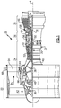
- FIG. 1 schematically illustrates an example gas turbine engine 20 that includes a fan section 22, a compressor section 24, a combustor section 26 and a turbine section 28.
- Alternative engines might include an augmenter section (not shown) among other systems or features.
- the fan section 22 drives air along a bypass flow path B while the compressor section 24 draws air in along a core flow path C where air is compressed and communicated to a combustor section 26.
- air is mixed with fuel and ignited to generate a high pressure exhaust gas stream that expands through the turbine section 28 where energy is extracted and utilized to drive the fan section 22 and the compressor section 24.
- turbofan gas turbine engine depicts a turbofan gas turbine engine
- the concepts described herein are not limited to use with turbofans as the teachings may be applied to other types of turbine engines; for example a turbine engine including a three-spool architecture in which three spools concentrically rotate about a common axis and where a low spool enables a low pressure turbine to drive a fan via a gearbox, an intermediate spool that enables an intermediate pressure turbine to drive a first compressor of the compressor section, and a high spool that enables a high pressure turbine to drive a high pressure compressor of the compressor section.
- the example engine 20 generally includes a low speed spool 30 and a high speed spool 32 mounted for rotation about an engine central longitudinal axis A relative to an engine static structure 36 via several bearing systems 38. It should be understood that various bearing systems 38 at various locations may alternatively or additionally be provided.
- the low speed spool 30 generally includes an inner shaft 40 that connects a fan 42 and a low pressure (or first) compressor section 44 to a low pressure (or first) turbine section 46.
- the inner shaft 40 drives the fan 42 through a speed change device, such as a geared architecture 48, to drive the fan 42 at a lower speed than the low speed spool 30.
- the high-speed spool 32 includes an outer shaft 50 that interconnects a high pressure (or second) compressor section 52 and a high pressure (or second) turbine section 54.
- the inner shaft 40 and the outer shaft 50 are concentric and rotate via the bearing systems 38 about the engine central longitudinal axis A.
- a combustor 56 is arranged between the high pressure compressor 52 and the high pressure turbine 54.
- the high pressure turbine 54 includes at least two stages to provide a double stage high pressure turbine 54.
- the high pressure turbine 54 includes only a single stage.
- a "high pressure" compressor or turbine experiences a higher pressure than a corresponding "low pressure” compressor or turbine.
- the example low pressure turbine 46 has a pressure ratio that is greater than about 5.
- the pressure ratio of the example low pressure turbine 46 is measured prior to an inlet of the low pressure turbine 46 as related to the pressure measured at the outlet of the low pressure turbine 46 prior to an exhaust nozzle.
- a mid-turbine frame 58 of the engine static structure 36 is arranged generally between the high pressure turbine 54 and the low pressure turbine 46.
- the mid-turbine frame 58 further supports bearing systems 38 in the turbine section 28 as well as setting airflow entering the low pressure turbine 46.
- Airflow through the core airflow path C is compressed by the low pressure compressor 44 then by the high pressure compressor 52 mixed with fuel and ignited in the combustor 56 to produce high speed exhaust gases that are then expanded through the high pressure turbine 54 and low pressure turbine 46.
- the mid-turbine frame 58 includes vanes 60, which are in the core airflow path and function as an inlet guide vane for the low pressure turbine 46. Utilizing the vane 60 of the mid-turbine frame 58 as the inlet guide vane for low pressure turbine 46 decreases the length of the low pressure turbine 46 without increasing the axial length of the mid-turbine frame 58. Reducing or eliminating the number of vanes in the low pressure turbine 46 shortens the axial length of the turbine section 28. Thus, the compactness of the gas turbine engine 20 is increased and a higher power density may be achieved.
- the disclosed gas turbine engine 20 in one example is a high-bypass geared aircraft engine.
- the gas turbine engine 20 includes a bypass ratio greater than about six (6), with an example embodiment being greater than about ten (10).
- the example geared architecture 48 is an epicyclical gear train, such as a planetary gear system, star gear system or other known gear system, with a gear reduction ratio of greater than about 2.3.
- the gas turbine engine 20 includes a bypass ratio greater than about ten (10:1) and the fan diameter is significantly larger than an outer diameter of the low pressure compressor 44. It should be understood, however, that the above parameters are only exemplary of one embodiment of a gas turbine engine including a geared architecture and that the present disclosure is applicable to other gas turbine engines.
- the fan section 22 of the engine 20 is designed for a particular flight condition -- typically cruise at about 0.8 Mach and about 10668 m (35,000 feet).
- the flight condition of 0.8 Mach and 10668 m (35,000 ft.), with the engine at its best fuel consumption - also known as "bucket cruise Thrust Specific Fuel Consumption ('TSFC')" - is the industry standard parameter of pound-mass (lbm) of fuel per hour being burned divided by pound-force (lbf) of thrust the engine produces at that minimum point.
- Low fan pressure ratio is the pressure ratio across the fan blade alone, without a Fan Exit Guide Vane (“FEGV”) system.
- the low fan pressure ratio as disclosed herein according to one non-limiting embodiment is less than about 1.50. In another non-limiting embodiment the low fan pressure ratio is less than about 1.45.
- Low corrected fan tip speed is the actual fan tip speed in ft/sec divided by an industry standard temperature correction of [(Tram °R)/(518.7°R)] 0.5 .
- the "Low corrected fan tip speed”, as disclosed herein according to one non-limiting embodiment, is less than about 345 m/s (1150 ft/second).
- the example gas turbine engine includes the fan 42 that comprises in one non-limiting embodiment less than about 26 fan blades. In another non-limiting embodiment, the fan section 22 includes less than about 20 fan blades. Moreover, in one disclosed embodiment the low pressure turbine 46 includes no more than about 6 turbine rotors schematically indicated at 34. In another non-limiting example embodiment the low pressure turbine 46 includes about 3 turbine rotors. A ratio between the number of fan blades 42 and the number of low pressure turbine rotors is between about 3.3 and about 8.6. The example low pressure turbine 46 provides the driving power to rotate the fan section 22 and therefore the relationship between the number of turbine rotors 34 in the low pressure turbine 46 and the number of blades 42 in the fan section 22 disclose an example gas turbine engine 20 with increased power transfer efficiency.
- a fan exit guide vane 64 is disposed within the bypass flow path B downstream of the fan section 22 and fan blades 42.
- the fan exit guide vane 64 includes an airfoil 64 supported between an outer diameter platform 68 and an inner diameter platform 66.
- the airfoil 64 removes swirl and other directional components of airflow from the fan 42 to improve airflow properties and characteristics.
- secondary flow structures such as vortices can be formed. Such vortices can result in losses in the duct.
- a contoured surface 78 is provided between adjacent guide vanes 64 to reduce the strength of secondary flow structures. This may increases flow efficiency and overall engine performance.
- the contoured surface 78 extends between a suction side 76 and a pressure side 74 of adjacent vanes 64.
- the platforms 66, 68 may include an axisymmetric cross section at a leading edge (LE) 70 and a trailing edge 72 (TE) of the vanes 64.
- the contoured surface 78 is disposed on the inner diameter platform 66. It is also within the contemplation of this disclosure that a contoured surface may also be provided on between vanes 64 on an inner side of the outer diameter platform 68.
- the contoured surface 78 begins at the suction side 76 of one vane 64 and transitions radially outward in a convex region 82. From the convex region 82, the surface transitions gradually radially inward toward a concave region 80. From the inner most part of the concave region 80, the surface 78 transitions radially outward to another convex region 82. As appreciated, the concave regions 80 are depressions within the surface 78 and the convex regions 82 are raised surfaces. The surface 78 transitions smoothly from one convex region 82 to the next convex region. Concave and convex regions 80, 82 may be composed of multiple subregions of varying concavity or convexity.
- the example contoured surface 78 provides hills or raised portions referred to as the convex regions 82 at the locations close to vanes 64.
- the contoured surface may include concave regions 80 close to the surfaces of the vanes 64.
- the concave regions 80 are disposed between the convex regions 82.
- the contoured surface 78 therefore defines a varying surface between vanes 64 that includes a series of ridges and troughs between vanes 64.
- Figures 3 and 4 show top-down and isometric views of an example contoured surface 78, respectively.
- the example contoured surface 78 is disposed on the inner diameter platform 66 and includes concave portions 80 and convex portions 82 that gradually transition from the suction side 76 of one vane 64 to the pressure side 74 of the adjacent vane 64.
- the example contoured surface 78 is spaced apart from both the leading edge (LE) 70 and the trailing edge (TE) 72.
- the contoured surface 78 does not extend axially past the leading and trailing edges 70, 72. That is, the contoured surface 78 may start aft of the leading edge 70 and end forward of the trailing edge 72, such that the airfoils 64 leading and trailing edges 70, 72 bound the axial extent of the contoured surface 78.
- Convex portions 82a, 182a are adjacent to the vanes 64 ( Figure 2 ) trailing edges 72 and extend toward a midchord region 79 of the vane 64.
- a concave portion 80 between the vanes 64 may have two prongs 81a, 81b oriented towards the trailing edge 72 of the vanes 64.
- a convex portion 82b may be between the two prongs 81a, 81b towards the trailing edge 72.
- An additional convex portion 82c may be located towards the leading edge of the adjacent vanes 64.
- An additional concave portion 180 may be located between the additional convex portion 82c and the pressure side 74 of the vane 64 ( Figure 2 ), adjacent to the leading edge 70 and extending towards the midchord 79 of the vane 64.
Landscapes
- Engineering & Computer Science (AREA)
- Mechanical Engineering (AREA)
- General Engineering & Computer Science (AREA)
- Physics & Mathematics (AREA)
- Fluid Mechanics (AREA)
- Chemical & Material Sciences (AREA)
- Combustion & Propulsion (AREA)
- Structures Of Non-Positive Displacement Pumps (AREA)
Claims (14)
- Mantelstromtriebwerk, das Folgendes umfasst:einen Lüfterabschnitt (22), der eine Vielzahl von Lüfterschaufeln beinhaltet, um eine Triebwerkachse drehbar ist und einen Luftstrom erzeugt;einen Nebenstromdurchlass (B), durch den der Luftstrom strömt; undeine Lüfterausgangsleitschaufelbaugruppe (64), die eine Vielzahl von Schaufelprofilen (64) beinhaltet, die zwischen einer inneren Plattformwand und einer äußeren Plattformwand angeordnet sind, wobei zumindest eine von der inneren Plattformwand und der äußeren Plattformwand eine konturierte Fläche (78) zwischen benachbarten der Vielzahl von Schaufelprofilen beinhaltet, und wobei die konturierte Fläche zumindest einen konkaven Bereich (80) und zumindest einen konvexen Bereich (82) beinhaltet, dadurch gekennzeichnet, dass der zumindest eine konvexe Bereich einen ersten und zweiten konvexen Bereich (82a, 182a) beinhaltet, der benachbart zu dem ersten bzw. zweiten Schaufelprofil der Vielzahl von Schaufelprofilen ist; wobei konvexe Abschnitte (82a, 182a) benachbart zu den Hinterkanten (72) der Schaufeln (64) sind und sich in Richtung eines Profilsehnenmittenbereichs (79) der Schaufel (64) erstrecken.
- Mantelstromtriebwerk nach Anspruch 1, wobei zumindest einer des zumindest einen konvexen Bereichs und des zumindest einen konkaven Bereichs einen Teilbereich mit einer Konkavität oder Konvexität umfasst, die sich von der des konvexen oder konkaven Bereichs unterscheidet.
- Mantelstromtriebwerk nach Anspruch 1 oder 2, wobei eine der inneren und äußeren Plattformwände einen achsensymmetrischen Querschnitt an einer Vorderkante (70) und einer Hinterkante (72) einer Ebene, die durch die benachbarten der Vielzahl von Schaufelprofilen definiert wird, aufweist und die Vorderkanten und Hinterkanten der benachbarten der Vielzahl von Schaufelprofilen an eine axiale Ausdehnung der konturierten Fläche angrenzen.
- Mantelstromtriebwerk nach Anspruch 1, 2 oder 3 wobei der erste und zweite konvexe Bereich sich axial von der Nähe einer ersten Profilsehnenmitte (79) des ersten Schaufelprofils und einer zweiten Profilsehnenmitte des zweiten Schaufelprofils zu der Nähe von Hinterkanten des ersten bzw. zweiten Schaufelprofils erstrecken.
- Mantelstromtriebwerk nach Anspruch 4, wobei der zumindest eine konkave Bereich einen ersten konkaven Bereich beinhaltet, der eine erste und zweite Spitze (81a, 81b) aufweist.
- Mantelstromtriebwerk nach Anspruch 5, wobei der zumindest eine konvexe Bereich einen dritten konvexen Bereich zwischen der ersten und zweiten Spitze des ersten konkaven Bereichs beinhaltet.
- Mantelstromtriebwerk nach Anspruch 5, wobei die erste und zweite Spitze in Richtung von Hinterkanten der benachbarten der Vielzahl von Schaufelprofilen ausgerichtet sind.
- Mantelstromtriebwerk nach Anspruch 7, das ferner einen zweiten konkaven Bereich umfasst, der benachbart zu einer Druckseite des ersten und zweiten Schaufelprofils ist.
- Mantelstromtriebwerk nach Anspruch 8, das ferner einen vierten konvexen Bereich zwischen dem ersten und zweiten konkaven Bereich umfasst.
- Mantelstromtriebwerk nach einem der vorstehenden Ansprüche, wobei die konturierte Fläche allmählich von dem zumindest einen konvexen Bereich zu dem zumindest einen konkaven Bereich übergeht.
- Verfahren zum Verringern sekundärer Strömungsstrukturen im Luftnebenstrom, das Folgendes umfasst:Bereitstellen eines Luftnebenstroms von einem Lüfter zu der Lüfterausgangsleitschaufelbaugruppe;Bereitstellen einer Lüfterausgangsleitschaufelbaugruppe, die eine Vielzahl von Schaufelprofilen beinhaltet, die zwischen einer inneren Plattformwand und einer äußeren Plattformwand angeordnet sind; undBereitstellen einer konturierten Fläche auf der inneren Plattformwand, wobei die konturierte Fläche zumindest einen konvexen Bereich und zumindest einen konkaven Bereich beinhaltet, dadurch gekennzeichnet, dass der zumindest eine konvexe Bereich einen ersten und zweiten konvexen Bereich (82a, 182a) beinhaltet, der benachbart zu dem ersten bzw. zweiten Schaufelprofil der Vielzahl von Schaufelprofilen ist; wobei konvexe Abschnitte (82a, 182a) benachbart zu den Hinterkanten (72) der Schaufeln (64) sind und sich in Richtung eines Profilsehnenmittenbereichs (79) der Schaufel (64) erstrecken.
- Verfahren nach Anspruch 11, wobei zumindest einer von dem zumindest einen konvexen Bereich und dem zumindest einen konkaven Bereich einen Teilbereich mit einer Konkavität oder Konvexität umfasst, die sich von der des konvexen oder konkaven Bereichs unterscheidet.
- Verfahren nach Anspruch 11 oder 12, wobei die innere Plattformwand die konturierte Fläche beinhaltet.
- Verfahren nach Anspruch 11, 12 oder 13, wobei sich die konturierte Fläche hinter den Vorderkanten und vor den Hinterkanten der benachbarten von der Vielzahl von Schaufelprofilen erstreckt.
Applications Claiming Priority (3)
| Application Number | Priority Date | Filing Date | Title |
|---|---|---|---|
| US201361786746P | 2013-03-15 | 2013-03-15 | |
| US201361823150P | 2013-05-14 | 2013-05-14 | |
| PCT/US2014/025386 WO2014197062A2 (en) | 2013-03-15 | 2014-03-13 | Fan exit guide vane platform contouring |
Publications (3)
| Publication Number | Publication Date |
|---|---|
| EP2971576A2 EP2971576A2 (de) | 2016-01-20 |
| EP2971576A4 EP2971576A4 (de) | 2016-12-21 |
| EP2971576B1 true EP2971576B1 (de) | 2020-06-24 |
Family
ID=52008705
Family Applications (1)
| Application Number | Title | Priority Date | Filing Date |
|---|---|---|---|
| EP14807829.8A Active EP2971576B1 (de) | 2013-03-15 | 2014-03-13 | Plattform zur konturierung einer lüfterausgangsleitschaufel |
Country Status (3)
| Country | Link |
|---|---|
| US (1) | US10196897B2 (de) |
| EP (1) | EP2971576B1 (de) |
| WO (1) | WO2014197062A2 (de) |
Families Citing this family (6)
| Publication number | Priority date | Publication date | Assignee | Title |
|---|---|---|---|---|
| GB201420010D0 (en) | 2014-11-11 | 2014-12-24 | Rolls Royce Plc | Gas turbine engine |
| GB201420011D0 (en) | 2014-11-11 | 2014-12-24 | Rolls Royce Plc | Gas turbine engine |
| US10968748B2 (en) | 2019-04-08 | 2021-04-06 | United Technologies Corporation | Non-axisymmetric end wall contouring with aft mid-passage peak |
| US10876411B2 (en) | 2019-04-08 | 2020-12-29 | United Technologies Corporation | Non-axisymmetric end wall contouring with forward mid-passage peak |
| US11492856B2 (en) | 2019-11-29 | 2022-11-08 | Canrig Robotic Technologies As | Inventory system |
| FR3106627B1 (fr) * | 2020-01-24 | 2023-03-17 | Safran Aircraft Engines | Basculement en vagues aux entrefers rotor-stator dans un compresseur de turbomachine |
Citations (1)
| Publication number | Priority date | Publication date | Assignee | Title |
|---|---|---|---|---|
| US20120201688A1 (en) * | 2011-02-08 | 2012-08-09 | Mtu Aero Engines Gmbh | Blade channel having an end wall contour and a turbomachine |
Family Cites Families (33)
| Publication number | Priority date | Publication date | Assignee | Title |
|---|---|---|---|---|
| JP2657555B2 (ja) * | 1988-10-29 | 1997-09-24 | 石川島播磨重工業株式会社 | ターボファンエンジンのファンケース用内装材 |
| US5215439A (en) | 1991-01-15 | 1993-06-01 | Northern Research & Engineering Corp. | Arbitrary hub for centrifugal impellers |
| US5369954A (en) * | 1991-04-22 | 1994-12-06 | General Electric Company | Turbofan engine bypass and exhaust system |
| US5397215A (en) | 1993-06-14 | 1995-03-14 | United Technologies Corporation | Flow directing assembly for the compression section of a rotary machine |
| GB2281356B (en) | 1993-08-20 | 1997-01-29 | Rolls Royce Plc | Gas turbine engine turbine |
| DE19650656C1 (de) | 1996-12-06 | 1998-06-10 | Mtu Muenchen Gmbh | Turbomaschine mit transsonischer Verdichterstufe |
| GB9823840D0 (en) | 1998-10-30 | 1998-12-23 | Rolls Royce Plc | Bladed ducting for turbomachinery |
| US6511294B1 (en) | 1999-09-23 | 2003-01-28 | General Electric Company | Reduced-stress compressor blisk flowpath |
| US6561761B1 (en) | 2000-02-18 | 2003-05-13 | General Electric Company | Fluted compressor flowpath |
| JP2001271602A (ja) | 2000-03-27 | 2001-10-05 | Honda Motor Co Ltd | ガスタービンエンジン |
| US6524070B1 (en) | 2000-08-21 | 2003-02-25 | General Electric Company | Method and apparatus for reducing rotor assembly circumferential rim stress |
| US6471474B1 (en) | 2000-10-20 | 2002-10-29 | General Electric Company | Method and apparatus for reducing rotor assembly circumferential rim stress |
| US6478545B2 (en) | 2001-03-07 | 2002-11-12 | General Electric Company | Fluted blisk |
| US6669445B2 (en) | 2002-03-07 | 2003-12-30 | United Technologies Corporation | Endwall shape for use in turbomachinery |
| US6969232B2 (en) | 2002-10-23 | 2005-11-29 | United Technologies Corporation | Flow directing device |
| US7690890B2 (en) * | 2004-09-24 | 2010-04-06 | Ishikawajima-Harima Heavy Industries Co. Ltd. | Wall configuration of axial-flow machine, and gas turbine engine |
| US7217096B2 (en) | 2004-12-13 | 2007-05-15 | General Electric Company | Fillet energized turbine stage |
| US7134842B2 (en) | 2004-12-24 | 2006-11-14 | General Electric Company | Scalloped surface turbine stage |
| GB0518628D0 (en) | 2005-09-13 | 2005-10-19 | Rolls Royce Plc | Axial compressor blading |
| JP4616781B2 (ja) | 2006-03-16 | 2011-01-19 | 三菱重工業株式会社 | タービン翼列エンドウォール |
| US7887297B2 (en) | 2006-05-02 | 2011-02-15 | United Technologies Corporation | Airfoil array with an endwall protrusion and components of the array |
| US20080072569A1 (en) * | 2006-09-27 | 2008-03-27 | Thomas Ory Moniz | Guide vane and method of fabricating the same |
| GB0704426D0 (en) | 2007-03-08 | 2007-04-18 | Rolls Royce Plc | Aerofoil members for a turbomachine |
| DE102007020025A1 (de) | 2007-04-27 | 2008-10-30 | Honda Motor Co., Ltd. | Form eines Gaskanals in einer Axialströmungs-Gasturbinenmaschine |
| US8459035B2 (en) | 2007-07-27 | 2013-06-11 | United Technologies Corporation | Gas turbine engine with low fan pressure ratio |
| US8206115B2 (en) | 2008-09-26 | 2012-06-26 | General Electric Company | Scalloped surface turbine stage with trailing edge ridges |
| US8231353B2 (en) | 2008-12-31 | 2012-07-31 | General Electric Company | Methods and apparatus relating to improved turbine blade platform contours |
| DE102009011924A1 (de) | 2009-03-10 | 2010-09-16 | Rolls-Royce Deutschland Ltd & Co Kg | Nebenstromkanal eines Turbofantriebwerks |
| US8105037B2 (en) | 2009-04-06 | 2012-01-31 | United Technologies Corporation | Endwall with leading-edge hump |
| EP2427634B1 (de) * | 2009-05-07 | 2018-04-11 | GKN Aerospace Sweden AB | Strebe und eine gasturbinenstruktur die strebe umfassend |
| US20120051930A1 (en) | 2010-08-31 | 2012-03-01 | General Electric Company | Shrouded turbine blade with contoured platform and axial dovetail |
| US8684684B2 (en) * | 2010-08-31 | 2014-04-01 | General Electric Company | Turbine assembly with end-wall-contoured airfoils and preferenttial clocking |
| JP6035946B2 (ja) * | 2012-07-26 | 2016-11-30 | 株式会社Ihi | エンジンダクト及び航空機エンジン |
-
2014
- 2014-03-13 EP EP14807829.8A patent/EP2971576B1/de active Active
- 2014-03-13 US US14/774,190 patent/US10196897B2/en active Active
- 2014-03-13 WO PCT/US2014/025386 patent/WO2014197062A2/en not_active Ceased
Patent Citations (1)
| Publication number | Priority date | Publication date | Assignee | Title |
|---|---|---|---|---|
| US20120201688A1 (en) * | 2011-02-08 | 2012-08-09 | Mtu Aero Engines Gmbh | Blade channel having an end wall contour and a turbomachine |
Also Published As
| Publication number | Publication date |
|---|---|
| WO2014197062A2 (en) | 2014-12-11 |
| WO2014197062A3 (en) | 2015-02-19 |
| EP2971576A2 (de) | 2016-01-20 |
| EP2971576A4 (de) | 2016-12-21 |
| US20160017715A1 (en) | 2016-01-21 |
| US10196897B2 (en) | 2019-02-05 |
Similar Documents
| Publication | Publication Date | Title |
|---|---|---|
| EP2964924B1 (de) | Gasturbinenmotoreinlass | |
| EP3480430B1 (de) | Integral beschaufelter rotor für ein gasturbinentriebwerk und verfahren zur herstellung eines integral beschaufelten rotors für ein gasturbinentriebwerk | |
| EP3187712B1 (de) | Kurzer gondeleinlass | |
| EP3033497B1 (de) | Gasturbinentriebwerk und zugehöriges montageverfahren | |
| EP2964932B1 (de) | Schaufel und zugehöriges gasturbinentriebwerk | |
| US9790861B2 (en) | Gas turbine engine having support structure with swept leading edge | |
| WO2014058478A1 (en) | Geared low fan pressure ratio fan exit guide vane stagger angle | |
| EP2882951B1 (de) | Schaufelprofil und verfahren zu deren herstellung | |
| EP2971576B1 (de) | Plattform zur konturierung einer lüfterausgangsleitschaufel | |
| EP2938830B1 (de) | Serpentinenförmiger kühlkanal mit winkelleisten in einem gasturbinentriebwerk | |
| EP3064711A1 (de) | Bauteil, zugehöriges gasturbinentriebwerk und verfahren | |
| EP3985226A1 (de) | Gasturbinentriebwerk-schaufelprofil | |
| EP3094823B1 (de) | Bauteil eines gasturbinentriebwerks und zugehöriges gasturbinentriebwerk | |
| EP3550108B1 (de) | Stirnwandkontur | |
| EP3477056B1 (de) | Gasturbinenmotorschaufelanordnung | |
| US20160032730A1 (en) | Obtuse angle chevron trip strip | |
| EP3061910A1 (de) | Gasturbinenmotor-tragfläche und entsprechendes herstellungsverfahren | |
| US20140219813A1 (en) | Gas turbine engine serpentine cooling passage | |
| EP2956626B1 (de) | Fanschaufel mit externen hohlräumen | |
| US20140083079A1 (en) | Geared turbofan primary and secondary nozzle integration geometry | |
| EP3181863B1 (de) | Gasturbinenmotor mit minimierter einlassverzerrung | |
| EP3108103B1 (de) | Fanschaufel für ein gastrubinentriebwerk | |
| EP3290717A1 (de) | Verdichterlaufschaufel mit spezifischem druck- und geschwindigkeitsprofil in schaufelhöhenrichtung |
Legal Events
| Date | Code | Title | Description |
|---|---|---|---|
| PUAI | Public reference made under article 153(3) epc to a published international application that has entered the european phase |
Free format text: ORIGINAL CODE: 0009012 |
|
| 17P | Request for examination filed |
Effective date: 20151006 |
|
| AK | Designated contracting states |
Kind code of ref document: A2 Designated state(s): AL AT BE BG CH CY CZ DE DK EE ES FI FR GB GR HR HU IE IS IT LI LT LU LV MC MK MT NL NO PL PT RO RS SE SI SK SM TR |
|
| AX | Request for extension of the european patent |
Extension state: BA ME |
|
| DAX | Request for extension of the european patent (deleted) | ||
| RAP1 | Party data changed (applicant data changed or rights of an application transferred) |
Owner name: UNITED TECHNOLOGIES CORPORATION |
|
| A4 | Supplementary search report drawn up and despatched |
Effective date: 20161122 |
|
| RIC1 | Information provided on ipc code assigned before grant |
Ipc: F01D 9/02 20060101AFI20161116BHEP Ipc: F02K 3/06 20060101ALI20161116BHEP Ipc: F01D 17/00 20060101ALI20161116BHEP Ipc: F01D 5/14 20060101ALI20161116BHEP Ipc: F02C 7/04 20060101ALI20161116BHEP |
|
| STAA | Information on the status of an ep patent application or granted ep patent |
Free format text: STATUS: EXAMINATION IS IN PROGRESS |
|
| 17Q | First examination report despatched |
Effective date: 20190528 |
|
| GRAP | Despatch of communication of intention to grant a patent |
Free format text: ORIGINAL CODE: EPIDOSNIGR1 |
|
| STAA | Information on the status of an ep patent application or granted ep patent |
Free format text: STATUS: GRANT OF PATENT IS INTENDED |
|
| INTG | Intention to grant announced |
Effective date: 20200206 |
|
| GRAS | Grant fee paid |
Free format text: ORIGINAL CODE: EPIDOSNIGR3 |
|
| GRAA | (expected) grant |
Free format text: ORIGINAL CODE: 0009210 |
|
| STAA | Information on the status of an ep patent application or granted ep patent |
Free format text: STATUS: THE PATENT HAS BEEN GRANTED |
|
| AK | Designated contracting states |
Kind code of ref document: B1 Designated state(s): AL AT BE BG CH CY CZ DE DK EE ES FI FR GB GR HR HU IE IS IT LI LT LU LV MC MK MT NL NO PL PT RO RS SE SI SK SM TR |
|
| REG | Reference to a national code |
Ref country code: GB Ref legal event code: FG4D |
|
| REG | Reference to a national code |
Ref country code: CH Ref legal event code: EP |
|
| REG | Reference to a national code |
Ref country code: DE Ref legal event code: R096 Ref document number: 602014067047 Country of ref document: DE |
|
| REG | Reference to a national code |
Ref country code: AT Ref legal event code: REF Ref document number: 1284093 Country of ref document: AT Kind code of ref document: T Effective date: 20200715 |
|
| REG | Reference to a national code |
Ref country code: IE Ref legal event code: FG4D |
|
| PG25 | Lapsed in a contracting state [announced via postgrant information from national office to epo] |
Ref country code: LT Free format text: LAPSE BECAUSE OF FAILURE TO SUBMIT A TRANSLATION OF THE DESCRIPTION OR TO PAY THE FEE WITHIN THE PRESCRIBED TIME-LIMIT Effective date: 20200624 Ref country code: FI Free format text: LAPSE BECAUSE OF FAILURE TO SUBMIT A TRANSLATION OF THE DESCRIPTION OR TO PAY THE FEE WITHIN THE PRESCRIBED TIME-LIMIT Effective date: 20200624 Ref country code: GR Free format text: LAPSE BECAUSE OF FAILURE TO SUBMIT A TRANSLATION OF THE DESCRIPTION OR TO PAY THE FEE WITHIN THE PRESCRIBED TIME-LIMIT Effective date: 20200925 Ref country code: NO Free format text: LAPSE BECAUSE OF FAILURE TO SUBMIT A TRANSLATION OF THE DESCRIPTION OR TO PAY THE FEE WITHIN THE PRESCRIBED TIME-LIMIT Effective date: 20200924 Ref country code: SE Free format text: LAPSE BECAUSE OF FAILURE TO SUBMIT A TRANSLATION OF THE DESCRIPTION OR TO PAY THE FEE WITHIN THE PRESCRIBED TIME-LIMIT Effective date: 20200624 |
|
| REG | Reference to a national code |
Ref country code: LT Ref legal event code: MG4D |
|
| PG25 | Lapsed in a contracting state [announced via postgrant information from national office to epo] |
Ref country code: BG Free format text: LAPSE BECAUSE OF FAILURE TO SUBMIT A TRANSLATION OF THE DESCRIPTION OR TO PAY THE FEE WITHIN THE PRESCRIBED TIME-LIMIT Effective date: 20200924 Ref country code: HR Free format text: LAPSE BECAUSE OF FAILURE TO SUBMIT A TRANSLATION OF THE DESCRIPTION OR TO PAY THE FEE WITHIN THE PRESCRIBED TIME-LIMIT Effective date: 20200624 Ref country code: RS Free format text: LAPSE BECAUSE OF FAILURE TO SUBMIT A TRANSLATION OF THE DESCRIPTION OR TO PAY THE FEE WITHIN THE PRESCRIBED TIME-LIMIT Effective date: 20200624 Ref country code: LV Free format text: LAPSE BECAUSE OF FAILURE TO SUBMIT A TRANSLATION OF THE DESCRIPTION OR TO PAY THE FEE WITHIN THE PRESCRIBED TIME-LIMIT Effective date: 20200624 |
|
| REG | Reference to a national code |
Ref country code: NL Ref legal event code: MP Effective date: 20200624 |
|
| REG | Reference to a national code |
Ref country code: AT Ref legal event code: MK05 Ref document number: 1284093 Country of ref document: AT Kind code of ref document: T Effective date: 20200624 |
|
| PG25 | Lapsed in a contracting state [announced via postgrant information from national office to epo] |
Ref country code: AL Free format text: LAPSE BECAUSE OF FAILURE TO SUBMIT A TRANSLATION OF THE DESCRIPTION OR TO PAY THE FEE WITHIN THE PRESCRIBED TIME-LIMIT Effective date: 20200624 Ref country code: NL Free format text: LAPSE BECAUSE OF FAILURE TO SUBMIT A TRANSLATION OF THE DESCRIPTION OR TO PAY THE FEE WITHIN THE PRESCRIBED TIME-LIMIT Effective date: 20200624 |
|
| PG25 | Lapsed in a contracting state [announced via postgrant information from national office to epo] |
Ref country code: RO Free format text: LAPSE BECAUSE OF FAILURE TO SUBMIT A TRANSLATION OF THE DESCRIPTION OR TO PAY THE FEE WITHIN THE PRESCRIBED TIME-LIMIT Effective date: 20200624 Ref country code: IT Free format text: LAPSE BECAUSE OF FAILURE TO SUBMIT A TRANSLATION OF THE DESCRIPTION OR TO PAY THE FEE WITHIN THE PRESCRIBED TIME-LIMIT Effective date: 20200624 Ref country code: SM Free format text: LAPSE BECAUSE OF FAILURE TO SUBMIT A TRANSLATION OF THE DESCRIPTION OR TO PAY THE FEE WITHIN THE PRESCRIBED TIME-LIMIT Effective date: 20200624 Ref country code: EE Free format text: LAPSE BECAUSE OF FAILURE TO SUBMIT A TRANSLATION OF THE DESCRIPTION OR TO PAY THE FEE WITHIN THE PRESCRIBED TIME-LIMIT Effective date: 20200624 Ref country code: CZ Free format text: LAPSE BECAUSE OF FAILURE TO SUBMIT A TRANSLATION OF THE DESCRIPTION OR TO PAY THE FEE WITHIN THE PRESCRIBED TIME-LIMIT Effective date: 20200624 Ref country code: ES Free format text: LAPSE BECAUSE OF FAILURE TO SUBMIT A TRANSLATION OF THE DESCRIPTION OR TO PAY THE FEE WITHIN THE PRESCRIBED TIME-LIMIT Effective date: 20200624 Ref country code: PT Free format text: LAPSE BECAUSE OF FAILURE TO SUBMIT A TRANSLATION OF THE DESCRIPTION OR TO PAY THE FEE WITHIN THE PRESCRIBED TIME-LIMIT Effective date: 20201026 Ref country code: AT Free format text: LAPSE BECAUSE OF FAILURE TO SUBMIT A TRANSLATION OF THE DESCRIPTION OR TO PAY THE FEE WITHIN THE PRESCRIBED TIME-LIMIT Effective date: 20200624 |
|
| PG25 | Lapsed in a contracting state [announced via postgrant information from national office to epo] |
Ref country code: SK Free format text: LAPSE BECAUSE OF FAILURE TO SUBMIT A TRANSLATION OF THE DESCRIPTION OR TO PAY THE FEE WITHIN THE PRESCRIBED TIME-LIMIT Effective date: 20200624 Ref country code: PL Free format text: LAPSE BECAUSE OF FAILURE TO SUBMIT A TRANSLATION OF THE DESCRIPTION OR TO PAY THE FEE WITHIN THE PRESCRIBED TIME-LIMIT Effective date: 20200624 Ref country code: IS Free format text: LAPSE BECAUSE OF FAILURE TO SUBMIT A TRANSLATION OF THE DESCRIPTION OR TO PAY THE FEE WITHIN THE PRESCRIBED TIME-LIMIT Effective date: 20201024 |
|
| RAP2 | Party data changed (patent owner data changed or rights of a patent transferred) |
Owner name: RAYTHEON TECHNOLOGIES CORPORATION |
|
| REG | Reference to a national code |
Ref country code: DE Ref legal event code: R097 Ref document number: 602014067047 Country of ref document: DE |
|
| PG25 | Lapsed in a contracting state [announced via postgrant information from national office to epo] |
Ref country code: DK Free format text: LAPSE BECAUSE OF FAILURE TO SUBMIT A TRANSLATION OF THE DESCRIPTION OR TO PAY THE FEE WITHIN THE PRESCRIBED TIME-LIMIT Effective date: 20200624 |
|
| PLBE | No opposition filed within time limit |
Free format text: ORIGINAL CODE: 0009261 |
|
| STAA | Information on the status of an ep patent application or granted ep patent |
Free format text: STATUS: NO OPPOSITION FILED WITHIN TIME LIMIT |
|
| 26N | No opposition filed |
Effective date: 20210325 |
|
| PG25 | Lapsed in a contracting state [announced via postgrant information from national office to epo] |
Ref country code: SI Free format text: LAPSE BECAUSE OF FAILURE TO SUBMIT A TRANSLATION OF THE DESCRIPTION OR TO PAY THE FEE WITHIN THE PRESCRIBED TIME-LIMIT Effective date: 20200624 |
|
| PG25 | Lapsed in a contracting state [announced via postgrant information from national office to epo] |
Ref country code: MC Free format text: LAPSE BECAUSE OF FAILURE TO SUBMIT A TRANSLATION OF THE DESCRIPTION OR TO PAY THE FEE WITHIN THE PRESCRIBED TIME-LIMIT Effective date: 20200624 |
|
| REG | Reference to a national code |
Ref country code: CH Ref legal event code: PL |
|
| REG | Reference to a national code |
Ref country code: BE Ref legal event code: MM Effective date: 20210331 |
|
| PG25 | Lapsed in a contracting state [announced via postgrant information from national office to epo] |
Ref country code: CH Free format text: LAPSE BECAUSE OF NON-PAYMENT OF DUE FEES Effective date: 20210331 Ref country code: LI Free format text: LAPSE BECAUSE OF NON-PAYMENT OF DUE FEES Effective date: 20210331 Ref country code: LU Free format text: LAPSE BECAUSE OF NON-PAYMENT OF DUE FEES Effective date: 20210313 Ref country code: IE Free format text: LAPSE BECAUSE OF NON-PAYMENT OF DUE FEES Effective date: 20210313 |
|
| PG25 | Lapsed in a contracting state [announced via postgrant information from national office to epo] |
Ref country code: BE Free format text: LAPSE BECAUSE OF NON-PAYMENT OF DUE FEES Effective date: 20210331 |
|
| PG25 | Lapsed in a contracting state [announced via postgrant information from national office to epo] |
Ref country code: HU Free format text: LAPSE BECAUSE OF FAILURE TO SUBMIT A TRANSLATION OF THE DESCRIPTION OR TO PAY THE FEE WITHIN THE PRESCRIBED TIME-LIMIT; INVALID AB INITIO Effective date: 20140313 |
|
| P01 | Opt-out of the competence of the unified patent court (upc) registered |
Effective date: 20230520 |
|
| PG25 | Lapsed in a contracting state [announced via postgrant information from national office to epo] |
Ref country code: CY Free format text: LAPSE BECAUSE OF FAILURE TO SUBMIT A TRANSLATION OF THE DESCRIPTION OR TO PAY THE FEE WITHIN THE PRESCRIBED TIME-LIMIT Effective date: 20200624 |
|
| PG25 | Lapsed in a contracting state [announced via postgrant information from national office to epo] |
Ref country code: MK Free format text: LAPSE BECAUSE OF FAILURE TO SUBMIT A TRANSLATION OF THE DESCRIPTION OR TO PAY THE FEE WITHIN THE PRESCRIBED TIME-LIMIT Effective date: 20200624 |
|
| PG25 | Lapsed in a contracting state [announced via postgrant information from national office to epo] |
Ref country code: TR Free format text: LAPSE BECAUSE OF FAILURE TO SUBMIT A TRANSLATION OF THE DESCRIPTION OR TO PAY THE FEE WITHIN THE PRESCRIBED TIME-LIMIT Effective date: 20200624 |
|
| PG25 | Lapsed in a contracting state [announced via postgrant information from national office to epo] |
Ref country code: MT Free format text: LAPSE BECAUSE OF FAILURE TO SUBMIT A TRANSLATION OF THE DESCRIPTION OR TO PAY THE FEE WITHIN THE PRESCRIBED TIME-LIMIT Effective date: 20200624 |
|
| REG | Reference to a national code |
Ref country code: DE Ref legal event code: R081 Ref document number: 602014067047 Country of ref document: DE Owner name: RTX CORPORATION (N.D.GES.D. STAATES DELAWARE),, US Free format text: FORMER OWNER: UNITED TECHNOLOGIES CORPORATION, FARMINGTON, CONN., US |
|
| PGFP | Annual fee paid to national office [announced via postgrant information from national office to epo] |
Ref country code: GB Payment date: 20260220 Year of fee payment: 13 |
|
| PGFP | Annual fee paid to national office [announced via postgrant information from national office to epo] |
Ref country code: DE Payment date: 20260219 Year of fee payment: 13 |
|
| PGFP | Annual fee paid to national office [announced via postgrant information from national office to epo] |
Ref country code: FR Payment date: 20260220 Year of fee payment: 13 |