EP2971768B2 - Développement d'un modèle supérieur pour contrôler et/ou surveiller un système de compresseurs - Google Patents
Développement d'un modèle supérieur pour contrôler et/ou surveiller un système de compresseurs Download PDFInfo
- Publication number
- EP2971768B2 EP2971768B2 EP14710264.4A EP14710264A EP2971768B2 EP 2971768 B2 EP2971768 B2 EP 2971768B2 EP 14710264 A EP14710264 A EP 14710264A EP 2971768 B2 EP2971768 B2 EP 2971768B2
- Authority
- EP
- European Patent Office
- Prior art keywords
- models
- compressor system
- model
- compressors
- peripheral devices
- Prior art date
- Legal status (The legal status is an assumption and is not a legal conclusion. Google has not performed a legal analysis and makes no representation as to the accuracy of the status listed.)
- Active
Links
Images



Classifications
-
- F—MECHANICAL ENGINEERING; LIGHTING; HEATING; WEAPONS; BLASTING
- F04—POSITIVE - DISPLACEMENT MACHINES FOR LIQUIDS; PUMPS FOR LIQUIDS OR ELASTIC FLUIDS
- F04B—POSITIVE-DISPLACEMENT MACHINES FOR LIQUIDS; PUMPS
- F04B51/00—Testing machines, pumps, or pumping installations
-
- F—MECHANICAL ENGINEERING; LIGHTING; HEATING; WEAPONS; BLASTING
- F04—POSITIVE - DISPLACEMENT MACHINES FOR LIQUIDS; PUMPS FOR LIQUIDS OR ELASTIC FLUIDS
- F04B—POSITIVE-DISPLACEMENT MACHINES FOR LIQUIDS; PUMPS
- F04B41/00—Pumping installations or systems specially adapted for elastic fluids
- F04B41/06—Combinations of two or more pumps
-
- F—MECHANICAL ENGINEERING; LIGHTING; HEATING; WEAPONS; BLASTING
- F04—POSITIVE - DISPLACEMENT MACHINES FOR LIQUIDS; PUMPS FOR LIQUIDS OR ELASTIC FLUIDS
- F04B—POSITIVE-DISPLACEMENT MACHINES FOR LIQUIDS; PUMPS
- F04B49/00—Control, e.g. of pump delivery, or pump pressure of, or safety measures for, machines, pumps, or pumping installations, not otherwise provided for, or of interest apart from, groups F04B1/00 - F04B47/00
- F04B49/007—Installations or systems with two or more pumps or pump cylinders, wherein the flow-path through the stages can be changed, e.g. from series to parallel
-
- F—MECHANICAL ENGINEERING; LIGHTING; HEATING; WEAPONS; BLASTING
- F04—POSITIVE - DISPLACEMENT MACHINES FOR LIQUIDS; PUMPS FOR LIQUIDS OR ELASTIC FLUIDS
- F04B—POSITIVE-DISPLACEMENT MACHINES FOR LIQUIDS; PUMPS
- F04B49/00—Control, e.g. of pump delivery, or pump pressure of, or safety measures for, machines, pumps, or pumping installations, not otherwise provided for, or of interest apart from, groups F04B1/00 - F04B47/00
- F04B49/06—Control using electricity
- F04B49/065—Control using electricity and making use of computers
-
- F—MECHANICAL ENGINEERING; LIGHTING; HEATING; WEAPONS; BLASTING
- F04—POSITIVE - DISPLACEMENT MACHINES FOR LIQUIDS; PUMPS FOR LIQUIDS OR ELASTIC FLUIDS
- F04D—NON-POSITIVE-DISPLACEMENT PUMPS
- F04D25/00—Pumping installations or systems
- F04D25/16—Combinations of two or more pumps ; Producing two or more separate gas flows
-
- F—MECHANICAL ENGINEERING; LIGHTING; HEATING; WEAPONS; BLASTING
- F04—POSITIVE - DISPLACEMENT MACHINES FOR LIQUIDS; PUMPS FOR LIQUIDS OR ELASTIC FLUIDS
- F04D—NON-POSITIVE-DISPLACEMENT PUMPS
- F04D27/00—Control, e.g. regulation, of pumps, pumping installations or pumping systems specially adapted for elastic fluids
- F04D27/001—Testing thereof; Determination or simulation of flow characteristics; Stall or surge detection, e.g. condition monitoring
-
- G—PHYSICS
- G05—CONTROLLING; REGULATING
- G05B—CONTROL OR REGULATING SYSTEMS IN GENERAL; FUNCTIONAL ELEMENTS OF SUCH SYSTEMS; MONITORING OR TESTING ARRANGEMENTS FOR SUCH SYSTEMS OR ELEMENTS
- G05B17/00—Systems involving the use of models or simulators of said systems
- G05B17/02—Systems involving the use of models or simulators of said systems electric
Definitions
- the invention relates to a method for monitoring a compressor system comprising one or more compressors and one or more peripheral devices, the compressors and peripheral devices being arranged or interconnected in a predetermined configuration, the compressor system being controlled and/or monitored via a control-monitoring unit.
- Compressor plants represent a system of a large number of compressors and peripheral devices of various types, which are coupled to one another via an air pipe network and, when using heat recovery systems, via a water pipe network.
- compressor systems are designed individually for the local conditions.
- control systems For the control and diagnosis of the compressors and peripheral devices in a compressor system, so-called higher-level station controls are used, which are comparable to control systems in process technology in terms of their task.
- control systems usually work with a control and analysis method that has been specially developed for the process to be controlled.
- the knowledge about the structure of the process to be controlled and the interrelationships between the individual components of the process is encoded in the special development.
- control and analysis methods specially developed for the compressor system to be controlled and monitored are the exception. Normally, a standard control and analysis method is used, which is only adapted to the on-site conditions by parameterization.
- the object of the present invention is to specify a method for monitoring a compressor system that takes the circumstances of a specific compressor system into account even more precisely.
- a core idea of the present invention is that based on one or more initial models M 1 , M 2 , derived models M ⁇ a , M ⁇ b , ..., which take into account the causal relationships between the individual compressors and peripheral devices and, if necessary, dynamic processes, is created and that one or more derived models M ⁇ a , M ⁇ b , ... the following Monitoring, diagnosis or evaluation routines are used as a basis.
- a derived model can result from exactly one initial model, for example.
- a derived model can result from two or more initial models or for two or more derived models to arise which are based on a single initial model.
- two or more derived models result from two or more original models.
- the derived model M a , M b can also be an intermediate model from which the end model is developed in one or more steps, which is ultimately used in subsequent monitoring, diagnostic or evaluation routines or on which these monitoring, diagnostic or evaluating routines are based.
- a monitoring, diagnostic or evaluation routine is to be understood quite generally as different monitoring tasks, diagnostic tasks or evaluation tasks.
- a predetermined configuration is the set of all conceivable configurations that the compressor system can assume in different operating states.
- the configuration should also be understood comprehensively in the form of a P&I diagram and in this respect the interrelationships of the compressors and peripheral devices should be recorded from different perspectives or in different domains, whereby for the implementation of the invention the recording of the interrelationships in one domain, from one perspective, is of course sufficient is.
- Possible domains or possible perspectives include, for example, but not exclusively, the compressed air technical causal relationships, which can be reproduced in a P&I diagram in the narrower sense, in particular a compressed air P&I diagram, the heat recovery-related causal relationships, which can be shown in a P&I diagram in the narrower sense, in particular in a heat recovery P&I diagram, the cooling water circuit-related interrelationships that can be reproduced in a R&I scheme in the narrower sense, in particular in a cooling water circuit P&I diagram, as well as the power supply-related interrelationships that are in an electrical Circuit diagram can be reproduced in consideration.
- a P&ID scheme within the meaning of the present invention can also be abstracted to the basic causal relationships viewed from one perspective/from one domain and in this respect does not have to include all the details of a possibly otherwise customary P&ID scheme.
- a graphic representation of the interrelationships in a specific perspective/in a particular domain can also be understood, such as a graphic representation of the interrelationships related to compressed air technology, a graphic representation of the interrelationships related to heat recovery.
- it is a flow diagram that shows the flow of energy and/or resources and/or Compressed air between the individual compressors and the individual peripherals reproduces.
- the derived model M ⁇ a , M ⁇ b , M 1 ', M 2 ', AAM 1 , AAM 2 is created.
- An aspect-specific model should be understood as a model that illuminates the compressor system with regard to a specific question. Conceivable aspects that could give rise to an aspect-specific model include, but are not limited to: humidity, pressure loss, compressed air quality, pressure quality, pressure behavior, energy efficiency, energy consumption, energy balance, temperatures, volume flows/mass flows, costs, degree of reserve and/or reliability.
- the information about the aspect-specific behavior of a compressor or a peripheral device is contained in one or more component models KM to be considered in the aspect output model AAM and/or in the analysis algorithm itself.
- the aspect-specific analysis algorithms encode how the initial models are to be interpreted with regard to one aspect (or several aspects).
- the aspect-specific analysis algorithms can also contain knowledge about the dynamic behavior of compressors and/or peripheral devices with regard to the aspect(s) under consideration.
- the aspect-specific analysis algorithm uses aspect-specific component models to create the derived models.
- an assigned analysis algorithm is provided for each aspect-specific model AM to be created.
- An analysis algorithm is normally developed specifically for a question that is to be answered with the aspect-specific model. In the case of related questions, it may be the case that the same or only slightly modified analysis algorithm can be used. As already mentioned, however, each aspect-specific question or each aspect-specific model is assigned a concrete analysis algorithm.
- derived models in particular intermediate models, can also be developed from analysis algorithms which in individual cases are the same or similar to the derived aspect-specific analysis algorithms.
- the derived model M ⁇ a , M ⁇ b , ... - regardless of whether it is a final or intermediate model - is stored in the control/monitoring unit or at the instigation of the control/ Monitoring unit is stored externally.
- the derived model or models M a , M b , . . . are derived and/or stored and/or used in an external system. In this case, one or more activities in connection with the derived models M a , M b , .
- the derived model or models M a , M b can be provided that the derived model or models M a , M b , .
- an improved database can result during the operation of the compressor system, so that this improved database can be the reason for an adjustment of the derived model or models.
- different domain-specific initial models can be taken into account for the creation of one or more derived models, be it as an intermediate or final model.
- domain specific Starting models can in particular be viewed as compressed air-specific starting models, power supply-specific starting models, starting models related to the cooling water circuit or starting models related to heat recovery, and in this respect two or more models from different domains can be combined or taken into account. Interactions between the different domains can also be recorded and mapped.
- an intermediate model is considered as a derived model, which also takes into account dynamic behavior or different operating states of the compressor system compared to the original model or models.
- An alternative or additional intermediate model which - if additional - can be hierarchically before or after the intermediate model discussed above, is that it is aspect-specifically adapted and possibly simplified compared to one or more initial models or compared to one or more intermediate models. If, for example, the question of which compressor is linked to a downstream dryer is examined in a compressor system, filters arranged in between play no role and can be left aside in an intermediate model from the perspective of this question, so that a simplified intermediate model can be defined.
- the starting model or models M 1 , M 2 is based on the specifically given configuration of the compressor system in the form of a P&I scheme, which is entered via an editor in particular after the compressor system has been created.
- the editor and/or the memory section can also be part of the control/monitoring unit or be integrated there.
- a prerequisite for creating the initial models is knowledge of the causal relationships in the compressor system. It is not absolutely necessary that the compressor system exists. In this way, one or more initial models or a P&ID scheme or several domain-specific P&ID schemes can already be created when planning a compressor system. It is also not necessary for the initial models to be created or the P&I diagrams to be entered immediately once the structure of the compressor system has been determined. The initial models or the R&I schemes must be specified or created at the latest when the P&I diagrams or the original models are to be used.
- the method according to the invention can also be carried out repeatedly, for example if something has changed in the specific configuration, i.e. in the real structure of the compressor system, or if an error was made when the P&I diagram was previously entered is.
- the control/monitoring unit can be designed as a unit that takes over both controlling and monitoring functions or only monitoring functions.
- An expedient development of the method provides that after the input of the specifically given configuration, this is stored at the instigation of the control/monitoring unit.
- the input of the R&I scheme exclusively includes the configuration or interconnection of the compressors and peripheral devices already known to the control/monitoring unit.
- the control/monitoring unit can already know the existence of a specific compressor or a specific peripheral device as such, or the control/monitoring unit can already know the specific specification of the existing compressors and peripheral devices in addition to the mere existence of specific compressors or specific peripheral devices be known.
- the input of the P&I scheme includes not only the input of the configuration or interconnection of the compressors and peripheral devices, but also the specific specification of the existing compressors and peripheral devices.
- the P&I scheme is entered by the user. Since compressors and/or peripheral devices from different manufacturers are often combined with one another on the part of the user to create a specific compressor system, the detection of the causal relationships on the part of the user is a preferred possible embodiment.
- the compressors and peripheral devices are specified or can be selected as corresponding graphic symbols.
- the links between the compressors and the peripheral devices are specified or can be selected as corresponding graphic symbols.
- the presence of one or more compressors and one or more peripheral devices and/or the specification of individual or all compressors and/or individual or all peripheral devices is transmitted externally, in particular by uploading corresponding information, for example as an upload of a file made available by the plant manufacturer.
- the selection of graphic symbols for representing compressors or peripheral devices and/or the selection of specific specifications and/or the selection of special links can be made by marking in a suggestion list, the selected object or the selected information can then be transferred to the P&I diagram to be created in the editor.
- this is a very concrete, possible embodiment. Numerous other modifications are conceivable, in particular in connection with a partial or exclusive textual input, an input using voice recognition or an input using image recognition.
- control/monitoring unit can be implemented in one server or in several servers that are operatively connected to one another or in a virtual computer.
- an aspect-specific model can preferably be created using an aspect-specific analysis algorithm.
- AAM can therefore be made from the aspect-specific initial model, in which, for example, the filters are peripheral devices that are not to be taken into account in the specific question were left aside, answer the question of which dryer can be supplied by which compressor using a suitable analysis algorithm.
- a compressor system comprising one or more compressors and one or more peripheral devices and a control/monitoring unit is also described, the compressors and peripheral devices being arranged or interconnected in a predetermined configuration, the compressor system being controlled and/or controlled via a control/monitoring unit or is monitored, which is characterized in that the control / monitoring unit is designed and set up in such a way that it in control, monitoring, diagnosis or evaluation routines on one or more derived models M ⁇ a , M b , ... the Compressor system resorts, which or which are created based on one or more output models M 1 , M 2 , ... the compressor system, but also consider interrelationships between the individual compressors and the peripherals and possibly also dynamic processes.
- control/monitoring unit stores the derived model or models M a , M b , . . .
- control/monitoring unit can be designed in such a way that it is implemented in one or more servers that are operatively connected to one another or in a virtual computer.
- control/monitoring unit also includes an editor and the editor is designed and intended for inputting the specifically given configuration of the compressor system in the form of a P&I diagram and the editor continues to be connected to the control /monitoring unit is operatively connected in such a way that the entered P&I scheme is transmitted to the control/monitoring unit and it serves there as a basis for creating one or more output models M 1 , M 2 , . . .
- a control/monitoring unit for controlling and/or monitoring a compressor system comprising one or more compressors and one or more peripheral devices, the compressors and peripheral devices being arranged or interconnected in a predetermined configuration and the control/monitoring unit being the controller and/or monitoring of the compressor system, characterized in that this is based on one or more output models M 1 , M 2 , ... of the compressor system, which is based, for example, on a P&I scheme, possibly including the specification of the compressors and the peripheral devices , one or more derived models that take into account the causal relationships between the individual compressors and peripheral devices and, if necessary, also dynamic processes, are created and that the one or more derived models M ⁇ a , M b , ... are used in subsequent control, monitoring, Diagnosis or evaluation routines are used as a basis.
- the compressor system can also include an editor which is designed and intended for entering the specifically given configuration in the form of an R&I diagram and which is operatively connected to the control/monitoring unit in such a way that that the entered P&I scheme is transmitted to the control/monitoring unit in order to use it as a basis for subsequent control, monitoring, diagnosis or evaluation routines.
- an editor which is designed and intended for entering the specifically given configuration in the form of an R&I diagram and which is operatively connected to the control/monitoring unit in such a way that that the entered P&I scheme is transmitted to the control/monitoring unit in order to use it as a basis for subsequent control, monitoring, diagnosis or evaluation routines.
- the control/monitoring unit takes care of the storage of the entered P&I diagram or diagrams.
- specifications of the compressors or peripheral devices used in the compressor system are stored in the control/monitoring unit such that the input of the P&ID scheme only includes the configuration or interconnection of the compressors and peripheral devices.
- control/monitoring unit in a memory section lists of specifications of possible compressors or peripheral devices and / or graphical symbols to represent compressors used or peripheral devices used and / or graphical symbols to represent possible links for selection position of a P&I diagram in the editor.
- the corresponding information or graphic symbols can be selected using various possible input options, such as cursor or mouse-controlled, text-controlled, voice-controlled, etc.
- the P&ID schema can be created in the editor using the selected symbols and/or information take place.
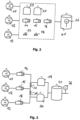
- FIG 1 an exemplary structure of a real given compressor system is illustrated.
- the exemplary compressor system should include three compressors 11, 12, 13 arranged in series with one another.
- Each compressor 11, 12, 13 can be uniquely assigned a filter 14, 15, 16, which is arranged downstream of the assigned compressor 11, 12, 13 in each case. Downstream of the filters 14, 15, 16, two dryers 19, 20 are arranged.
- the compressed air downstream of the first filter 14 should always flow through the first dryer 19 .
- the compressed air downstream of the second filter 15 can be routed via two valves 17, 18 either via the first dryer 19 or via the second dryer 20.
- the two valves 17, 18 are designed or controlled in such a way that they are never opened simultaneously, ie when the first valve 17 opens, the second valve 18 remains closed or when the second valve 18 opens, the first valve 17 remains closed.
- a compressed air reservoir 21 is arranged downstream of the two dryers 19 , 20 .
- a pressure sensor 26 is also arranged on the downstream side of the compressed air reservoir 21 for detecting the operating pressure present there.
- a control/monitoring unit 22 is provided for controlling and/or monitoring the compressor system, which is connected to the compressors 11, 12, 13 and the filters 14, 15, 16, the valves 17, 18, the dryers 19, 20, the compressed air reservoir 21 and the pressure sensor 26 is in operative connection.
- the filters 14, 15, 16, the valves 17, 18, the dryers 19, 20, the compressed air reservoir 21 and the pressure sensor 26 form peripheral devices of the compressor system.
- the control/monitoring unit 22 is still standing still in operative connection with a memory section 24 and an editor 23 .
- the control/monitoring unit 22 can perform control functions, monitoring functions or control and monitoring functions.
- monitoring is to be understood to mean any form of evaluation, i.e. in addition to monitoring for malfunctions, unusual operating states, alarm situations, etc., also a diagnosis, in particular if an error message is already present, an evaluation with regard to optimization or an evaluation to predict a next one maintenance appointment (predictive maintenance).
- models of the functional relationships between the compressors 11, 12, 13 and the peripheral devices 14 to 21 must be recorded and made accessible to the control/monitoring unit 22.
- the specifically given configuration in the form of a P&ID scheme is preferably entered via an editor 23 which is operatively connected to the control/monitoring unit 22 .
- one or more output models M 1 , M 2 and based on these initial models M 1 , M 2 , ... one or more derived models M a , M b , ... that take into account the causal relationships between the individual compressors 11 , 12 , 13 and peripheral devices 14 to 21 are developed.
- the functional relationship between the individual compressors 11, 12, 13 and the peripheral devices 14 to 21, in the present example specifically the filter 14, 15, 16, the dryer 19, 20 and the valves 17, 18 and the compressed air reservoir 21, is not taken into account .
- the peripheral devices of the compressed air treatment and the interconnection of these peripheral devices are nothing more than a black box from a structural point of view, which the compressor system does not accurately depict in this respect.
- the present invention therefore provides that, in order to create a model of the compressor system, in particular after the compressor system has been created, the specifically given configuration is entered in the form of a P&I diagram via the editor 23 already mentioned.
- One for the compressor system after figure 1 representative P&ID is in figure 3 played back. It should be noted that many variants are conceivable for entering this P&ID scheme.
- the input of the P&I scheme should at least include the step of determining the functional relationships between the compressors 11, 12, 13 and the peripheral devices 14 to 21, but can preferably also include a preliminary step, namely the detection of the presence of the compressors 11, 12, 13 and of the individual peripheral devices 14 to 21, preferably also a further third step, namely entering the specifications of the compressors 11, 12, 13 and the peripheral devices 14 to 21.
- FIG 4 a derived model M' is illustrated which is already different possible operating states of the initial model given as a P&ID scheme figure 3 depicted and taken into account. While in the model after figure 3 the information about which dryer 19, 20 is supplied by which compressor 11, 12, 13 is not yet included, takes into account in figure 4 Model M' illustrated the different circumstances by making the case distinction, " if the first valve 17 and the second valve 18 are closed, then ..., otherwise ".
- V1 designates the first valve 17, V2 the second valve 18.
- T1 designates the first dryer 19, T2 the second dryer 20, K1 designates the first compressor 11, K2 the second compressor 12 and K13 the third compressor 13.
- figure 5 is one from the P&ID scheme figure 3 illustrated as a starting model derived model that can be viewed as a simplified aspect-specific starting model AAM.
- a starting model derived model that can be viewed as a simplified aspect-specific starting model AAM.
- an assigned analysis algorithm can be stored at a corresponding location, in particular stored in the access area of the control and monitoring unit 22 .
- Aspect-specific component models can be integrated in a database, for example.
- the analysis algorithm knows that for the question of which dryer 19, 20 is supplied by which compressor 11, 12, 13, the output model according to figure 3 existing filters 14, 15, 16 can be disregarded.
- the question arises that in figure 5 illustrated aspect-specific starting model AAM, compared to the starting model figure 3 is simplified to the effect that the filters 14, 15, 16 are disregarded.
- the aspect-specific model AM is now shown, which is derived from the aspect-specific initial model figure 5 for the question which of the dryers 19, 20 is supplied by which compressor 11, 12, 13.
- the aspect-specific starting model AAM is used, which can be viewed as an intermediate model and is based on the starting model M figure 3 based.
- FIG 7 different paths for the development of an aspect-specific model AM (or an aspect-specific end model) from an initial model M are shown.
- Either models M′ or models AAM come into consideration as intermediate models, with the models M′ defining one (or optionally several) models in a generalized manner for a domain/an angle of view, which define, for example, different operating states of one or several initial models.
- Aspect-specific initial models AAM form the basis for arriving at an aspect-specific model AM with the help of an analysis algorithm and/or taking component models into account.
- figure 8 is a schematic overview of the individual process steps and the advantages that can be achieved from them, if on the one hand the interrelationships between the compressors and peripheral devices of a compressor system are taken into account in the form of a P&ID scheme as the basis for one or more initial models and on the other hand derived models are developed from these initial models .
- figure 8 illustrates the connections between the individual applications of models.
- the causal relationships shown in the figure should be read both cumulatively and alternatively.
- the basis for the processing of data is the standardization of the data in the sense that a well-defined meaning is assigned to each individual piece of data.
- aspect-specific models AM can be derived, which can be used for numerous other applications. Concrete conceivable applications are, for example, control and regulation, optimization of the boundary conditions under which a specific compressor system is operated, data analysis, monitoring, diagnosis, forecast of a maintenance appointment (predictive maintenance). With regard to the application of control and regulation, it can be stated that the operation of a compressor system can be improved by using models to determine and implement control actions for the compressors and/or peripheral devices under given boundary conditions (e.g. required pressure to be maintained) of the compressor system. This is an optimization that is applied in real time (online application).
- aspect specific models can be created.
- quantitative or qualitative statements can be considered for most conceivable applications, not only in data analysis but also in monitoring, diagnosis, etc.
- a quantitative statement can be made in the sense of a mean time to failure quantification, for example 10,000 hours.
- a statement illuminating the reliability of the compressor system can also be made qualitatively, for example as follows: The reliability of the compressor system is rated "high", “medium”, “low”.
- An example of an optimization can be the determination of the demand pressure parameter. This optimization can take place both as an offline optimization and during ongoing operation of the compressor system. In this regard, reference is made to the illustration figure 9 referenced, which makes the problem of optimizing the demand pressure to the actually necessary pressure easier to understand.
- the main specification for a control/monitoring unit of a compressor system is the minimum pressure (demand pressure) that must be present at the transfer point to the customer network.
- the control/monitoring unit 22 attempts to control the compressors 11, 12, 13 in such a way that the required pressure (p required ) is always maintained and the electrical energy required for generating compressed air is minimized.
- a sudden increase in compressed air consumption can result in the control/monitoring unit issuing a switch-on command to a compressor 11, 12, 13 too late, and the required pressure is therefore not reached. Therefore, the demand pressure (p demand ) in the control/monitoring unit is always set slightly higher than the pressure that the customer actually requires (p necessary ).
- the distance between the set demand pressure p demand and the actually necessary pressure p demand is a safety cushion.
- the minimum required pressure can be determined from the pressure curve profiles recorded in the past, at which the pressure that is actually required is no longer undershot.
- a simulation model of the compressor system derived from the R&I diagram of the compressor system, the minimum required pressure can be determined from the pressure curve profiles recorded in the past, at which the pressure that is actually required is no longer undershot.
- Models are used to monitor compressor systems. By comparing the behavior of the real process with the model of the real process, it can be recognized when behavior occurs in the real process that was not expected (at least taking the model into account). If reality and the model diverge, a warning or fault is triggered, for example an alarm signal is triggered or an e-mail is sent to a person responsible for the system.
- the cause of a malfunction is narrowed down or determined with the help of models.
- various error scenarios are simulated on the model and compared with the data observed in the real process when the error occurs.
- the scenario that best matches reality gives an indication of the cause of the error.
- a prognosis can be made for the next maintenance date for the compressor system, for individual compressors or individual peripheral devices.
- derived models can be used for advance simulation.
- a derived model for advance simulation can be used to predict how the individual compressors or peripheral devices of the compressor system will behave over time for a given compressed air consumption profile Switching commands to the compressors are calculated as they would result in the real compressor system for the given compressed air consumption profile.
- the running behavior of the compressors can be derived from the switching commands to the compressors.
- the running behavior of the compressors describes the operating status of a compressor and when.
- the results of the advance simulation can be used to determine when a state of wear will be reached that requires maintenance might.
- the state of wear of a maintenance-relevant component/operating material is determined based on the running hours of a compressor. For example, the oil needs to be changed every 3,000 operating hours. In the future, it will be possible to determine the state of wear of a maintenance-relevant component/operating material not only by the number of operating hours, but also by the environmental/operating conditions of the compressor system.
- model for the advance simulation for the determination of the state of wear represent relevant effects (e.g. compression temperature, pressure in the oil separator tank, particle load of the intake air, ambient temperature) with sufficient accuracy
- forecasts for maintenance measures can also be made if the state of wear of the affected component/operating material is not the only factor can be determined from the running hours.
- the accuracy of the prediction of the date for the next maintenance measure naturally depends on the extent to which the course of compressed air consumption assumed in the advance simulation actually occurs in reality.
- An advantage of forecasting the next maintenance date based on advance simulations compared to the trivial method of extrapolating running hours is that a forecast is also possible if the composition of the compressed air station changes (e.g. adding or removing a compressor) or a re-parameterization of the compressed air control is made (e.g. changing the order in which compressors are switched on and off).
- the prognosis for the implementation of the next maintenance measure is repeated regularly (e.g. once a day), with the course of the compressor states observed in the current compressor system since the last prognosis was carried out for the Implementation of a new forecast is used.
- the forecast for the next maintenance date becomes more and more accurate over time, since the proportion of wear that is actually observed is included in the forecast and thus the proportion of wear that still occurs up to the next maintenance (as an uncertainty in the model) becomes ever smaller.
- the four process steps described are decoupled from one another both in terms of location and time. There is only a temporal link (before-after link) between the procedural steps, i.e. some procedural steps must be carried out before other procedural steps and their results must be made available before other procedural steps that use the results from previous procedural steps can run. However, the process steps can be distributed to different systems (but do not have to be). However, if the procedural steps run on different systems, there must be an option for exchanging information (at least unidirectionally).
- compressors was used in general, without specifying the specific type of compressor.
- all of the compressors can be configured as positive-displacement compressors, for example, although this is only to be regarded as a special configuration and is not generally mandatory.
Landscapes
- Engineering & Computer Science (AREA)
- Mechanical Engineering (AREA)
- General Engineering & Computer Science (AREA)
- Physics & Mathematics (AREA)
- General Physics & Mathematics (AREA)
- Automation & Control Theory (AREA)
- Computer Hardware Design (AREA)
- Testing And Monitoring For Control Systems (AREA)
- Control Of Positive-Displacement Pumps (AREA)
- Analysing Materials By The Use Of Radiation (AREA)
Claims (13)
- Procédé pour la surveillance d'une installation de compresseurs comprenant un ou plusieurs compresseurs (11, 12, 13) et un ou plusieurs appareils périphériques (14 à 21),dans lequel les compresseurs (11, 12, 13) et les appareils périphériques (14 à 21) sont disposés et raccordés selon une configuration prédéterminée,dans lequel l'installation de compresseurs est commandée et/ou surveillée par une unité de commande et/ou de surveillance (22),lequel procédé génère un pronostic pour la prochaine date d'entretien de l'installation de compresseurs ou de certains compresseurs ou de certains appareils périphériques, caractérisé en ce que,- en particulier après la création de l'installation de compresseurs, la configuration effectivement obtenue est saisie sous la forme d'un schéma de P&ID à l'aide d'un éditeur (23) et cette saisie constitue la base d'un ou plusieurs modèles initiaux,- en ce que sont créés, sur la base de ces modèles initiaux (M1, M2, ...), un ou plusieurs modèles dérivés (M̃a, M̃b, ...) prenant en compte les relations d'action entre les différents compresseurs (11, 12, 13) et les appareils périphériques (14 à 21) et éventuellement aussi des processus dynamiques, et- un pronostic de prochaine date d'entretien est généré en prenant en compte des données de fonctionnement standardisées de l'installation de compresseurs à l'aide du ou des modèles dérivés (M̃a,M̃b, ...).
- Procédé pour la surveillance d'une installation de compresseurs comprenant un ou plusieurs compresseurs (11, 12, 13) et un ou plusieurs appareils périphériques (14 à 21),dans lequel les compresseurs (11, 12, 13) et les appareils périphériques (14 à 21) sont disposés et raccordés selon une configuration prédéterminée,dans lequel l'installation de compresseurs est commandée et/ou surveillée par une unité de commande et/ou de surveillance (22),lequel procédé est conçu comme un procédé de diagnostic pour le diagnostic de l'installation de compresseurs ou de certains compresseurs ou de certains appareils périphériques, caractérisé en ce que,- en particulier après la création de l'installation de compresseurs, la configuration effectivement obtenue est saisie sous la forme d'un schéma de P&ID à l'aide d'un éditeur (23) et cette saisie constitue la base d'un ou plusieurs modèles initiaux,- en ce que sont créés, sur la base de ces modèles initiaux (M1, M2, ...), un ou plusieurs modèles dérivés (M̃a , M̃b, ...) prenant en compte les relations d'action entre les différents compresseurs (11, 12, 13) et les appareils périphériques (14 à 21) et éventuellement aussi des processus dynamiques, et- un diagnostic de défauts est exécuté en prenant en compte des données de fonctionnement standardisées de l'installation de compresseurs à l'aide du ou des modèles dérivés (M̃a, M̃b, ...).
- Procédé selon la revendication 1 ou 2, caractérisé en ce que le modèle dérivé (M̃a , M̃b, ...) est un modèle spécifique d'un aspect (AM) qui est créé en utilisant un algorithme d'analyse spécifique d'un aspect à partir du ou des modèles initiaux (M1, M2, ...) ou d'un ou plusieurs modèles intermédiaires (M1', M2', ..., AAM1, AAM2, ...).
- Procédé selon la revendication 3, caractérisé en ce que l'information sur le comportement spécifique d'un aspect d'un compresseur (11, 12, 13) ou d'un appareil périphérique (14 à 21) est contenue dans un ou plusieurs modèles de composant (KM) à prendre en compte dans le modèle initial d'aspect (AAM) et/ou dans l'algorithme d'analyse même.
- Procédé selon la revendication 3 ou 4, caractérisé en ce qu'un algorithme d'analyse est prévu pour chaque modèle spécifique d'un aspect (AM) à créer.
- Procédé selon l'une des revendications 1 à 5, caractérisé en ce que le modèle dérivé (M̃a, M̃b, ...) est stocké dans l'unité centrale de commande/ surveillance (22).
- Procédé selon l'une des revendications 1 à 6, caractérisé en ce que le ou les modèles dérivés (M̃a , M̃b , ...) peuvent être dérivés et/ou stockés et/ou utilisés dans un système externe.
- Procédé selon l'une des revendications 1 à 7, caractérisé en ce que le ou les modèles dérivés (M̃a , M̃b , ...) sont vérifiés en continu ou de façon cyclique ou lors des événements et éventuellement sont ajustés automatiquement.
- Procédé selon l'une des revendications 1 à 8, caractérisé en ce que le ou les modèles dérivés sont adaptés aussi lors d'un changement du ou des modèles dérivés (M̃a , M̃b , ...) et/ou lors d'un changement d'un modèle de composant (KM), par exemple lors de changements de la construction de l'installation de compresseurs.
- Procédé selon l'une des revendications 1 à 9, caractérisé en ce que différents modèles initiaux (M1, M2, ...) spécifiques d'un domaine, en particulier un ou plusieurs modèles initiaux spécifiques de l'air comprimé, un ou plusieurs modèles initiaux spécifiques de l'alimentation électrique, un ou plusieurs modèles initiaux relatifs au circuit d'eau de refroidissement ou un ou plusieurs modèles initiaux relatifs à la récupération de chaleur, sont pris en compte.
- Procédé selon l'une des revendications 1 à 10, caractérisé en ce que le modèle dérivé (M̃a , M̃b , ...) est un modèle intermédiaire (M1', M2', ...) qui prend en compte aussi un comportement dynamique ou des états de fonctionnement différents de l'installation de compresseurs par rapport au(x) modèle(s) initial/initiaux.
- Procédé selon l'une des revendications 1 à 11, caractérisé en ce que le modèle dérivé (M̃a , M̃b , ...) est un modèle intermédiaire (AAM1, AAM2, ...) ajusté de façon spécifique de l'aspect et éventuellement simplifié par rapport à un ou plusieurs modèles initiaux (M1, M2, ...) ou à un ou plusieurs autres modèles intermédiaires (M1', M2', ...).
- Procédé selon l'une des revendications 1 à 12, caractérisé en ce que la configuration de l'installation de compresseurs effectivement réalisée et saisie en particulier après sa création à l'aide d'un éditeur (23) sous la forme d'un schéma de P&ID sert de base au(x) modèle(s) initial/initiaux (M1, M2 ...).
Priority Applications (2)
| Application Number | Priority Date | Filing Date | Title |
|---|---|---|---|
| EP19216644.5A EP3640477B1 (fr) | 2013-03-15 | 2014-03-14 | Développement d'un modèle parent pour commander et/ou surveiller une installation de compresseur |
| EP14710264.4A EP2971768B2 (fr) | 2013-03-15 | 2014-03-14 | Développement d'un modèle supérieur pour contrôler et/ou surveiller un système de compresseurs |
Applications Claiming Priority (3)
| Application Number | Priority Date | Filing Date | Title |
|---|---|---|---|
| EP13159616.5A EP2778412B1 (fr) | 2013-03-15 | 2013-03-15 | Développement d'un modèle supérieur pour contrôler et/ou surveiller un système de compresseurs |
| PCT/EP2014/055073 WO2014140253A1 (fr) | 2013-03-15 | 2014-03-14 | Développement d'un modèle d'ordre supérieur |
| EP14710264.4A EP2971768B2 (fr) | 2013-03-15 | 2014-03-14 | Développement d'un modèle supérieur pour contrôler et/ou surveiller un système de compresseurs |
Related Child Applications (2)
| Application Number | Title | Priority Date | Filing Date |
|---|---|---|---|
| EP19216644.5A Division-Into EP3640477B1 (fr) | 2013-03-15 | 2014-03-14 | Développement d'un modèle parent pour commander et/ou surveiller une installation de compresseur |
| EP19216644.5A Division EP3640477B1 (fr) | 2013-03-15 | 2014-03-14 | Développement d'un modèle parent pour commander et/ou surveiller une installation de compresseur |
Publications (3)
| Publication Number | Publication Date |
|---|---|
| EP2971768A1 EP2971768A1 (fr) | 2016-01-20 |
| EP2971768B1 EP2971768B1 (fr) | 2019-12-25 |
| EP2971768B2 true EP2971768B2 (fr) | 2023-04-05 |
Family
ID=47901814
Family Applications (3)
| Application Number | Title | Priority Date | Filing Date |
|---|---|---|---|
| EP13159616.5A Active EP2778412B1 (fr) | 2013-03-15 | 2013-03-15 | Développement d'un modèle supérieur pour contrôler et/ou surveiller un système de compresseurs |
| EP14710264.4A Active EP2971768B2 (fr) | 2013-03-15 | 2014-03-14 | Développement d'un modèle supérieur pour contrôler et/ou surveiller un système de compresseurs |
| EP19216644.5A Active EP3640477B1 (fr) | 2013-03-15 | 2014-03-14 | Développement d'un modèle parent pour commander et/ou surveiller une installation de compresseur |
Family Applications Before (1)
| Application Number | Title | Priority Date | Filing Date |
|---|---|---|---|
| EP13159616.5A Active EP2778412B1 (fr) | 2013-03-15 | 2013-03-15 | Développement d'un modèle supérieur pour contrôler et/ou surveiller un système de compresseurs |
Family Applications After (1)
| Application Number | Title | Priority Date | Filing Date |
|---|---|---|---|
| EP19216644.5A Active EP3640477B1 (fr) | 2013-03-15 | 2014-03-14 | Développement d'un modèle parent pour commander et/ou surveiller une installation de compresseur |
Country Status (5)
| Country | Link |
|---|---|
| US (2) | US11136974B2 (fr) |
| EP (3) | EP2778412B1 (fr) |
| ES (2) | ES2776004T3 (fr) |
| MX (1) | MX373422B (fr) |
| WO (1) | WO2014140253A1 (fr) |
Families Citing this family (7)
| Publication number | Priority date | Publication date | Assignee | Title |
|---|---|---|---|---|
| EP2778413B1 (fr) * | 2013-03-15 | 2016-03-02 | Kaeser Kompressoren Se | Entrée de schéma R&I pour un procédé de contrôle et/ou de surveillance d'un système de compresseurs |
| US11270043B2 (en) * | 2014-02-04 | 2022-03-08 | Ingersoll-Rand Industrial U.S., Inc. | System and method for modeling, simulation, optimization, and/or quote creation |
| US20150220669A1 (en) * | 2014-02-04 | 2015-08-06 | Ingersoll-Rand Company | System and Method for Modeling, Simulation, Optimization, and/or Quote Creation |
| US10845792B2 (en) * | 2017-03-24 | 2020-11-24 | Kabushiki Kaisha Toshiba | Failure diagnosis apparatus, monitoring apparatus, failure diagnosis method and recording medium |
| CN107740761B (zh) * | 2017-10-17 | 2018-10-09 | 通辽霍林河坑口发电有限责任公司 | 给水泵控制方法及给水系统 |
| DE102022132003A1 (de) * | 2022-12-02 | 2024-06-13 | Kaeser Kompressoren Se | Verfahren zur steuerung einer kompressoranlage mit mehreren kompressoren |
| FR3164256A1 (fr) * | 2024-07-03 | 2026-01-09 | Clauger | Procédé d’estimation d’un intervalle de révision mécanique d’un compresseur industriel de type ouvert à flux alternatif ou continu |
Citations (5)
| Publication number | Priority date | Publication date | Assignee | Title |
|---|---|---|---|---|
| US20060015315A1 (en) † | 2003-11-19 | 2006-01-19 | Schneider Electric Gmbh | Process for developing and implementing a model for the formal description of a collaborative system comprised of multiple distributed components, especially an intelligent, flexible production and/or process automation system |
| US20070005805A1 (en) † | 2003-02-28 | 2007-01-04 | Peter Drath | System and method for managing and exchanging the data of a technical project, technical installation and individual installation components |
| US20090292514A1 (en) † | 2008-02-15 | 2009-11-26 | Invensys Systems, Inc. | System And Method For Autogenerating Simulations For Process Control System Checkout And Operator Training |
| US20120029706A1 (en) † | 2008-12-23 | 2012-02-02 | Kaeser Kompressoren Gmbh | Simulation-Supported Method for Controlling and Regulating Compressed Air Stations |
| CA2842914A1 (fr) † | 2011-07-25 | 2013-01-31 | Siemens Aktiengesellschaft | Procede et dispositif de commande ou de regulation d'un circulateur de fluide pour la circulation d'un fluide a l'interieur d'une conduite de fluide |
Family Cites Families (9)
| Publication number | Priority date | Publication date | Assignee | Title |
|---|---|---|---|---|
| DE19826169A1 (de) * | 1998-06-13 | 1999-12-16 | Kaeser Kompressoren Gmbh | Elektronische Steuerung für Anlagen der Druckluft- und Vakuumerzeugung |
| AU2001247336B2 (en) * | 2000-03-10 | 2006-02-02 | Smiths Detection, Inc. | Control for an industrial process using one or more multidimensional variables |
| US20030097243A1 (en) * | 2001-10-23 | 2003-05-22 | Mays Thomas Gilmore | Method and system for operating a hydrocarbon production facility |
| US7415312B2 (en) * | 2004-05-25 | 2008-08-19 | Barnett Jr James R | Process module tuning |
| FR2879770B1 (fr) * | 2004-12-17 | 2007-03-30 | Air Liquide | Procede de controle des performances energetiques d'une unite industrielle |
| DE102005006410A1 (de) * | 2005-02-11 | 2006-08-17 | Siemens Ag | Verfahren zur Optimierung des Betriebs mehrerer Verdichteraggregate und Vorrichtung hierzu |
| US8032340B2 (en) * | 2007-01-04 | 2011-10-04 | Fisher-Rosemount Systems, Inc. | Method and system for modeling a process variable in a process plant |
| US8494798B2 (en) * | 2008-09-02 | 2013-07-23 | Mks Instruments, Inc. | Automated model building and batch model building for a manufacturing process, process monitoring, and fault detection |
| JP5634907B2 (ja) * | 2011-02-10 | 2014-12-03 | 株式会社日立製作所 | 圧縮機の制御装置及び制御方法 |
-
2013
- 2013-03-15 EP EP13159616.5A patent/EP2778412B1/fr active Active
- 2013-03-15 ES ES13159616T patent/ES2776004T3/es active Active
-
2014
- 2014-03-14 ES ES14710264T patent/ES2776728T5/es active Active
- 2014-03-14 WO PCT/EP2014/055073 patent/WO2014140253A1/fr not_active Ceased
- 2014-03-14 EP EP14710264.4A patent/EP2971768B2/fr active Active
- 2014-03-14 EP EP19216644.5A patent/EP3640477B1/fr active Active
- 2014-03-14 US US14/776,387 patent/US11136974B2/en active Active
- 2014-03-14 MX MX2015012382A patent/MX373422B/es active IP Right Grant
-
2021
- 2021-10-04 US US17/493,074 patent/US12313058B2/en active Active
Patent Citations (5)
| Publication number | Priority date | Publication date | Assignee | Title |
|---|---|---|---|---|
| US20070005805A1 (en) † | 2003-02-28 | 2007-01-04 | Peter Drath | System and method for managing and exchanging the data of a technical project, technical installation and individual installation components |
| US20060015315A1 (en) † | 2003-11-19 | 2006-01-19 | Schneider Electric Gmbh | Process for developing and implementing a model for the formal description of a collaborative system comprised of multiple distributed components, especially an intelligent, flexible production and/or process automation system |
| US20090292514A1 (en) † | 2008-02-15 | 2009-11-26 | Invensys Systems, Inc. | System And Method For Autogenerating Simulations For Process Control System Checkout And Operator Training |
| US20120029706A1 (en) † | 2008-12-23 | 2012-02-02 | Kaeser Kompressoren Gmbh | Simulation-Supported Method for Controlling and Regulating Compressed Air Stations |
| CA2842914A1 (fr) † | 2011-07-25 | 2013-01-31 | Siemens Aktiengesellschaft | Procede et dispositif de commande ou de regulation d'un circulateur de fluide pour la circulation d'un fluide a l'interieur d'une conduite de fluide |
Also Published As
| Publication number | Publication date |
|---|---|
| US20160032918A1 (en) | 2016-02-04 |
| EP2971768A1 (fr) | 2016-01-20 |
| MX373422B (es) | 2020-06-08 |
| ES2776728T5 (es) | 2023-08-11 |
| EP2778412A1 (fr) | 2014-09-17 |
| ES2776728T3 (es) | 2020-07-31 |
| EP3640477A1 (fr) | 2020-04-22 |
| WO2014140253A1 (fr) | 2014-09-18 |
| US20220025881A1 (en) | 2022-01-27 |
| EP2971768B1 (fr) | 2019-12-25 |
| EP2778412B1 (fr) | 2019-12-25 |
| ES2776004T3 (es) | 2020-07-28 |
| US11136974B2 (en) | 2021-10-05 |
| MX2015012382A (es) | 2016-02-03 |
| US12313058B2 (en) | 2025-05-27 |
| EP3640477B1 (fr) | 2025-08-06 |
Similar Documents
| Publication | Publication Date | Title |
|---|---|---|
| EP2971768B2 (fr) | Développement d'un modèle supérieur pour contrôler et/ou surveiller un système de compresseurs | |
| EP1543394B1 (fr) | Procede et dispositif pour surveiller une installation technique comprenant plusieurs systemes, notamment une centrale electrique | |
| DE102006046870B4 (de) | Prozessmodellidentifizierung in einem Prozesssteuersystem | |
| DE60212121T2 (de) | Erzeugung von prozessverwandten daten | |
| EP2350757B1 (fr) | Système et procédé de prise de decision optimisee pour un reseau d'alimentation en eau potable et/ou un entreprise de distribution d'eau | |
| EP0789861B1 (fr) | Procede d'analyse des donnees d'operations d'une installation technique | |
| DE112018002433T5 (de) | Verfahren und System zur parallelen Steuerung einer intelligenten Werkstatt | |
| WO2020216530A1 (fr) | Procédé servant à définir des cycles d'utilisation restante, circuit de définition de cycle d'utilisation restante, dispositif de définition de cycle d'utilisation restante | |
| DE112010001881T5 (de) | Verfahren zum Überwachen von Anlagen über eine installierte Basis zum Verbessern von Design und Leistung der Anlagen | |
| EP4193227A1 (fr) | Dispositif et procédé de détection d'anomalies dans une installation industrielle pour l'exécution d'un processus de production | |
| EP2971769B1 (fr) | Entrée de schéma r&i pour un procédé de contrôle et/ou de surveillance d'un système de compresseurs | |
| DE102020200051A1 (de) | Verfahren zum Bestimmen von Restnutzungszyklen, Restnutzungszyklusbestimmungsschaltung, Restnutzungszyklusbestimmungsvorrichtung | |
| WO2022152752A1 (fr) | Procédé de fourniture d'au moins un élément d'informations relatives à un système hydraulique | |
| EP1205830A1 (fr) | Procédé, produit d'un programme d'ordinateur et système d'informatique utilisé pour l'entretien | |
| EP3045726B1 (fr) | Normalisation de valeurs mesurees | |
| EP1431927A1 (fr) | Méthode pour estimer la durée de vie résiduelle d'un appareil | |
| DE102021205175A1 (de) | Selbsttätig adaptives Überwachungsverfahren für ein Gerät in einer Anlage | |
| EP3686697A1 (fr) | Optimisation du régulateur pour un système de commande d'une installation technique | |
| WO2023117410A1 (fr) | Dispositif d'analyse permettant l'identification d'installations de production et la surveillance de processus | |
| AT12161U1 (de) | Verfahren zur bewertung der betriebsgüte einer modularen betriebsleiteinrichtung | |
| EP3959571A1 (fr) | Procédé servant à définir des cycles d'utilisation restante, circuit de définition de cycle d'utilisation restante, dispositif de définition de cycle d'utilisation restante | |
| DE102020121890A1 (de) | Verfahren zur Diagnose eines Steuer- und/oder Regelungssystems sowie Steuer- und/oder Regelungssystem | |
| WO2025157475A1 (fr) | Procédé pour fournir en continu des données de mesure d'une variable de mesure d'un transformateur de puissance | |
| EP4127848A1 (fr) | Procédé et système de diagnostic de messages | |
| WO2013044963A1 (fr) | Procédé de détermination de paramètres relatifs à des composants et dispositif associé |
Legal Events
| Date | Code | Title | Description |
|---|---|---|---|
| PUAI | Public reference made under article 153(3) epc to a published international application that has entered the european phase |
Free format text: ORIGINAL CODE: 0009012 |
|
| 17P | Request for examination filed |
Effective date: 20151002 |
|
| AK | Designated contracting states |
Kind code of ref document: A1 Designated state(s): AL AT BE BG CH CY CZ DE DK EE ES FI FR GB GR HR HU IE IS IT LI LT LU LV MC MK MT NL NO PL PT RO RS SE SI SK SM TR |
|
| AX | Request for extension of the european patent |
Extension state: BA ME |
|
| DAX | Request for extension of the european patent (deleted) | ||
| STAA | Information on the status of an ep patent application or granted ep patent |
Free format text: STATUS: EXAMINATION IS IN PROGRESS |
|
| 17Q | First examination report despatched |
Effective date: 20180928 |
|
| REG | Reference to a national code |
Ref country code: DE Ref legal event code: R079 Ref document number: 502014013327 Country of ref document: DE Free format text: PREVIOUS MAIN CLASS: F04B0041060000 Ipc: F04B0051000000 |
|
| GRAP | Despatch of communication of intention to grant a patent |
Free format text: ORIGINAL CODE: EPIDOSNIGR1 |
|
| STAA | Information on the status of an ep patent application or granted ep patent |
Free format text: STATUS: GRANT OF PATENT IS INTENDED |
|
| RIC1 | Information provided on ipc code assigned before grant |
Ipc: F25D 1/00 20060101ALI20190524BHEP Ipc: F04B 51/00 20060101AFI20190524BHEP Ipc: F25B 1/00 20060101ALI20190524BHEP Ipc: F04D 27/00 20060101ALI20190524BHEP Ipc: G05B 17/02 20060101ALI20190524BHEP Ipc: F04B 49/00 20060101ALI20190524BHEP Ipc: G05B 1/00 20060101ALI20190524BHEP Ipc: G05D 1/00 20060101ALI20190524BHEP Ipc: F04B 49/06 20060101ALI20190524BHEP Ipc: F04D 25/16 20060101ALI20190524BHEP Ipc: F04B 41/06 20060101ALI20190524BHEP |
|
| INTG | Intention to grant announced |
Effective date: 20190617 |
|
| GRAS | Grant fee paid |
Free format text: ORIGINAL CODE: EPIDOSNIGR3 |
|
| GRAJ | Information related to disapproval of communication of intention to grant by the applicant or resumption of examination proceedings by the epo deleted |
Free format text: ORIGINAL CODE: EPIDOSDIGR1 |
|
| GRAL | Information related to payment of fee for publishing/printing deleted |
Free format text: ORIGINAL CODE: EPIDOSDIGR3 |
|
| STAA | Information on the status of an ep patent application or granted ep patent |
Free format text: STATUS: EXAMINATION IS IN PROGRESS |
|
| GRAR | Information related to intention to grant a patent recorded |
Free format text: ORIGINAL CODE: EPIDOSNIGR71 |
|
| STAA | Information on the status of an ep patent application or granted ep patent |
Free format text: STATUS: GRANT OF PATENT IS INTENDED |
|
| GRAA | (expected) grant |
Free format text: ORIGINAL CODE: 0009210 |
|
| STAA | Information on the status of an ep patent application or granted ep patent |
Free format text: STATUS: THE PATENT HAS BEEN GRANTED |
|
| INTC | Intention to grant announced (deleted) | ||
| AK | Designated contracting states |
Kind code of ref document: B1 Designated state(s): AL AT BE BG CH CY CZ DE DK EE ES FI FR GB GR HR HU IE IS IT LI LT LU LV MC MK MT NL NO PL PT RO RS SE SI SK SM TR |
|
| INTG | Intention to grant announced |
Effective date: 20191118 |
|
| REG | Reference to a national code |
Ref country code: GB Ref legal event code: FG4D Free format text: NOT ENGLISH |
|
| REG | Reference to a national code |
Ref country code: CH Ref legal event code: EP |
|
| REG | Reference to a national code |
Ref country code: AT Ref legal event code: REF Ref document number: 1217410 Country of ref document: AT Kind code of ref document: T Effective date: 20200115 |
|
| REG | Reference to a national code |
Ref country code: DE Ref legal event code: R096 Ref document number: 502014013327 Country of ref document: DE |
|
| REG | Reference to a national code |
Ref country code: IE Ref legal event code: FG4D Free format text: LANGUAGE OF EP DOCUMENT: GERMAN |
|
| REG | Reference to a national code |
Ref country code: NL Ref legal event code: MP Effective date: 20191225 |
|
| PG25 | Lapsed in a contracting state [announced via postgrant information from national office to epo] |
Ref country code: FI Free format text: LAPSE BECAUSE OF FAILURE TO SUBMIT A TRANSLATION OF THE DESCRIPTION OR TO PAY THE FEE WITHIN THE PRESCRIBED TIME-LIMIT Effective date: 20191225 Ref country code: BG Free format text: LAPSE BECAUSE OF FAILURE TO SUBMIT A TRANSLATION OF THE DESCRIPTION OR TO PAY THE FEE WITHIN THE PRESCRIBED TIME-LIMIT Effective date: 20200325 Ref country code: LT Free format text: LAPSE BECAUSE OF FAILURE TO SUBMIT A TRANSLATION OF THE DESCRIPTION OR TO PAY THE FEE WITHIN THE PRESCRIBED TIME-LIMIT Effective date: 20191225 Ref country code: SE Free format text: LAPSE BECAUSE OF FAILURE TO SUBMIT A TRANSLATION OF THE DESCRIPTION OR TO PAY THE FEE WITHIN THE PRESCRIBED TIME-LIMIT Effective date: 20191225 Ref country code: GR Free format text: LAPSE BECAUSE OF FAILURE TO SUBMIT A TRANSLATION OF THE DESCRIPTION OR TO PAY THE FEE WITHIN THE PRESCRIBED TIME-LIMIT Effective date: 20200326 Ref country code: LV Free format text: LAPSE BECAUSE OF FAILURE TO SUBMIT A TRANSLATION OF THE DESCRIPTION OR TO PAY THE FEE WITHIN THE PRESCRIBED TIME-LIMIT Effective date: 20191225 Ref country code: NO Free format text: LAPSE BECAUSE OF FAILURE TO SUBMIT A TRANSLATION OF THE DESCRIPTION OR TO PAY THE FEE WITHIN THE PRESCRIBED TIME-LIMIT Effective date: 20200325 |
|
| REG | Reference to a national code |
Ref country code: LT Ref legal event code: MG4D |
|
| PG25 | Lapsed in a contracting state [announced via postgrant information from national office to epo] |
Ref country code: RS Free format text: LAPSE BECAUSE OF FAILURE TO SUBMIT A TRANSLATION OF THE DESCRIPTION OR TO PAY THE FEE WITHIN THE PRESCRIBED TIME-LIMIT Effective date: 20191225 Ref country code: HR Free format text: LAPSE BECAUSE OF FAILURE TO SUBMIT A TRANSLATION OF THE DESCRIPTION OR TO PAY THE FEE WITHIN THE PRESCRIBED TIME-LIMIT Effective date: 20191225 |
|
| PG25 | Lapsed in a contracting state [announced via postgrant information from national office to epo] |
Ref country code: AL Free format text: LAPSE BECAUSE OF FAILURE TO SUBMIT A TRANSLATION OF THE DESCRIPTION OR TO PAY THE FEE WITHIN THE PRESCRIBED TIME-LIMIT Effective date: 20191225 |
|
| PG25 | Lapsed in a contracting state [announced via postgrant information from national office to epo] |
Ref country code: NL Free format text: LAPSE BECAUSE OF FAILURE TO SUBMIT A TRANSLATION OF THE DESCRIPTION OR TO PAY THE FEE WITHIN THE PRESCRIBED TIME-LIMIT Effective date: 20191225 Ref country code: PT Free format text: LAPSE BECAUSE OF FAILURE TO SUBMIT A TRANSLATION OF THE DESCRIPTION OR TO PAY THE FEE WITHIN THE PRESCRIBED TIME-LIMIT Effective date: 20200520 Ref country code: CZ Free format text: LAPSE BECAUSE OF FAILURE TO SUBMIT A TRANSLATION OF THE DESCRIPTION OR TO PAY THE FEE WITHIN THE PRESCRIBED TIME-LIMIT Effective date: 20191225 Ref country code: RO Free format text: LAPSE BECAUSE OF FAILURE TO SUBMIT A TRANSLATION OF THE DESCRIPTION OR TO PAY THE FEE WITHIN THE PRESCRIBED TIME-LIMIT Effective date: 20191225 Ref country code: EE Free format text: LAPSE BECAUSE OF FAILURE TO SUBMIT A TRANSLATION OF THE DESCRIPTION OR TO PAY THE FEE WITHIN THE PRESCRIBED TIME-LIMIT Effective date: 20191225 |
|
| REG | Reference to a national code |
Ref country code: ES Ref legal event code: FG2A Ref document number: 2776728 Country of ref document: ES Kind code of ref document: T3 Effective date: 20200731 |
|
| PG25 | Lapsed in a contracting state [announced via postgrant information from national office to epo] |
Ref country code: IS Free format text: LAPSE BECAUSE OF FAILURE TO SUBMIT A TRANSLATION OF THE DESCRIPTION OR TO PAY THE FEE WITHIN THE PRESCRIBED TIME-LIMIT Effective date: 20200425 Ref country code: SK Free format text: LAPSE BECAUSE OF FAILURE TO SUBMIT A TRANSLATION OF THE DESCRIPTION OR TO PAY THE FEE WITHIN THE PRESCRIBED TIME-LIMIT Effective date: 20191225 Ref country code: SM Free format text: LAPSE BECAUSE OF FAILURE TO SUBMIT A TRANSLATION OF THE DESCRIPTION OR TO PAY THE FEE WITHIN THE PRESCRIBED TIME-LIMIT Effective date: 20191225 |
|
| REG | Reference to a national code |
Ref country code: DE Ref legal event code: R026 Ref document number: 502014013327 Country of ref document: DE |
|
| PLBI | Opposition filed |
Free format text: ORIGINAL CODE: 0009260 |
|
| PLAX | Notice of opposition and request to file observation + time limit sent |
Free format text: ORIGINAL CODE: EPIDOSNOBS2 |
|
| PG25 | Lapsed in a contracting state [announced via postgrant information from national office to epo] |
Ref country code: MC Free format text: LAPSE BECAUSE OF FAILURE TO SUBMIT A TRANSLATION OF THE DESCRIPTION OR TO PAY THE FEE WITHIN THE PRESCRIBED TIME-LIMIT Effective date: 20191225 Ref country code: DK Free format text: LAPSE BECAUSE OF FAILURE TO SUBMIT A TRANSLATION OF THE DESCRIPTION OR TO PAY THE FEE WITHIN THE PRESCRIBED TIME-LIMIT Effective date: 20191225 |
|
| REG | Reference to a national code |
Ref country code: CH Ref legal event code: PL |
|
| 26 | Opposition filed |
Opponent name: ATLAS COPCO AIRPOWER N.V. Effective date: 20200925 |
|
| PG25 | Lapsed in a contracting state [announced via postgrant information from national office to epo] |
Ref country code: SI Free format text: LAPSE BECAUSE OF FAILURE TO SUBMIT A TRANSLATION OF THE DESCRIPTION OR TO PAY THE FEE WITHIN THE PRESCRIBED TIME-LIMIT Effective date: 20191225 |
|
| PG25 | Lapsed in a contracting state [announced via postgrant information from national office to epo] |
Ref country code: LU Free format text: LAPSE BECAUSE OF NON-PAYMENT OF DUE FEES Effective date: 20200314 |
|
| PG25 | Lapsed in a contracting state [announced via postgrant information from national office to epo] |
Ref country code: LI Free format text: LAPSE BECAUSE OF NON-PAYMENT OF DUE FEES Effective date: 20200331 Ref country code: CH Free format text: LAPSE BECAUSE OF NON-PAYMENT OF DUE FEES Effective date: 20200331 Ref country code: IE Free format text: LAPSE BECAUSE OF NON-PAYMENT OF DUE FEES Effective date: 20200314 |
|
| PLBB | Reply of patent proprietor to notice(s) of opposition received |
Free format text: ORIGINAL CODE: EPIDOSNOBS3 |
|
| PG25 | Lapsed in a contracting state [announced via postgrant information from national office to epo] |
Ref country code: PL Free format text: LAPSE BECAUSE OF FAILURE TO SUBMIT A TRANSLATION OF THE DESCRIPTION OR TO PAY THE FEE WITHIN THE PRESCRIBED TIME-LIMIT Effective date: 20191225 |
|
| REG | Reference to a national code |
Ref country code: AT Ref legal event code: MM01 Ref document number: 1217410 Country of ref document: AT Kind code of ref document: T Effective date: 20200314 |
|
| PG25 | Lapsed in a contracting state [announced via postgrant information from national office to epo] |
Ref country code: AT Free format text: LAPSE BECAUSE OF NON-PAYMENT OF DUE FEES Effective date: 20200314 |
|
| PG25 | Lapsed in a contracting state [announced via postgrant information from national office to epo] |
Ref country code: TR Free format text: LAPSE BECAUSE OF FAILURE TO SUBMIT A TRANSLATION OF THE DESCRIPTION OR TO PAY THE FEE WITHIN THE PRESCRIBED TIME-LIMIT Effective date: 20191225 Ref country code: MT Free format text: LAPSE BECAUSE OF FAILURE TO SUBMIT A TRANSLATION OF THE DESCRIPTION OR TO PAY THE FEE WITHIN THE PRESCRIBED TIME-LIMIT Effective date: 20191225 Ref country code: CY Free format text: LAPSE BECAUSE OF FAILURE TO SUBMIT A TRANSLATION OF THE DESCRIPTION OR TO PAY THE FEE WITHIN THE PRESCRIBED TIME-LIMIT Effective date: 20191225 |
|
| APAH | Appeal reference modified |
Free format text: ORIGINAL CODE: EPIDOSCREFNO |
|
| APBM | Appeal reference recorded |
Free format text: ORIGINAL CODE: EPIDOSNREFNO |
|
| APBP | Date of receipt of notice of appeal recorded |
Free format text: ORIGINAL CODE: EPIDOSNNOA2O |
|
| PG25 | Lapsed in a contracting state [announced via postgrant information from national office to epo] |
Ref country code: MK Free format text: LAPSE BECAUSE OF FAILURE TO SUBMIT A TRANSLATION OF THE DESCRIPTION OR TO PAY THE FEE WITHIN THE PRESCRIBED TIME-LIMIT Effective date: 20191225 |
|
| APBU | Appeal procedure closed |
Free format text: ORIGINAL CODE: EPIDOSNNOA9O |
|
| PUAH | Patent maintained in amended form |
Free format text: ORIGINAL CODE: 0009272 |
|
| STAA | Information on the status of an ep patent application or granted ep patent |
Free format text: STATUS: PATENT MAINTAINED AS AMENDED |
|
| 27A | Patent maintained in amended form |
Effective date: 20230405 |
|
| AK | Designated contracting states |
Kind code of ref document: B2 Designated state(s): AL AT BE BG CH CY CZ DE DK EE ES FI FR GB GR HR HU IE IS IT LI LT LU LV MC MK MT NL NO PL PT RO RS SE SI SK SM TR |
|
| REG | Reference to a national code |
Ref country code: DE Ref legal event code: R102 Ref document number: 502014013327 Country of ref document: DE |
|
| P01 | Opt-out of the competence of the unified patent court (upc) registered |
Effective date: 20230531 |
|
| REG | Reference to a national code |
Ref country code: ES Ref legal event code: DC2A Ref document number: 2776728 Country of ref document: ES Kind code of ref document: T5 Effective date: 20230811 |
|
| PGFP | Annual fee paid to national office [announced via postgrant information from national office to epo] |
Ref country code: GB Payment date: 20240319 Year of fee payment: 11 |
|
| PGFP | Annual fee paid to national office [announced via postgrant information from national office to epo] |
Ref country code: FR Payment date: 20240326 Year of fee payment: 11 |
|
| PGFP | Annual fee paid to national office [announced via postgrant information from national office to epo] |
Ref country code: ES Payment date: 20240412 Year of fee payment: 11 |
|
| PGFP | Annual fee paid to national office [announced via postgrant information from national office to epo] |
Ref country code: DE Payment date: 20250331 Year of fee payment: 12 |
|
| GBPC | Gb: european patent ceased through non-payment of renewal fee |
Effective date: 20250314 |
|
| PG25 | Lapsed in a contracting state [announced via postgrant information from national office to epo] |
Ref country code: GB Free format text: LAPSE BECAUSE OF NON-PAYMENT OF DUE FEES Effective date: 20250314 |
|
| PG25 | Lapsed in a contracting state [announced via postgrant information from national office to epo] |
Ref country code: FR Free format text: LAPSE BECAUSE OF NON-PAYMENT OF DUE FEES Effective date: 20250331 |
|
| PGFP | Annual fee paid to national office [announced via postgrant information from national office to epo] |
Ref country code: BE Payment date: 20260323 Year of fee payment: 13 Ref country code: IT Payment date: 20260320 Year of fee payment: 13 |