EP2972067B1 - Positionsmessung mit abgewinkelten kollektoren - Google Patents
Positionsmessung mit abgewinkelten kollektoren Download PDFInfo
- Publication number
- EP2972067B1 EP2972067B1 EP14769448.3A EP14769448A EP2972067B1 EP 2972067 B1 EP2972067 B1 EP 2972067B1 EP 14769448 A EP14769448 A EP 14769448A EP 2972067 B1 EP2972067 B1 EP 2972067B1
- Authority
- EP
- European Patent Office
- Prior art keywords
- magnet
- magnetic
- collectors
- collector
- sensor
- Prior art date
- Legal status (The legal status is an assumption and is not a legal conclusion. Google has not performed a legal analysis and makes no representation as to the accuracy of the status listed.)
- Active
Links
Images


Classifications
-
- G—PHYSICS
- G01—MEASURING; TESTING
- G01D—MEASURING NOT SPECIALLY ADAPTED FOR A SPECIFIC VARIABLE; ARRANGEMENTS FOR MEASURING TWO OR MORE VARIABLES NOT COVERED IN A SINGLE OTHER SUBCLASS; TARIFF METERING APPARATUS; MEASURING OR TESTING NOT OTHERWISE PROVIDED FOR
- G01D5/00—Mechanical means for transferring the output of a sensing member; Means for converting the output of a sensing member to another variable where the form or nature of the sensing member does not constrain the means for converting; Transducers not specially adapted for a specific variable
- G01D5/12—Mechanical means for transferring the output of a sensing member; Means for converting the output of a sensing member to another variable where the form or nature of the sensing member does not constrain the means for converting; Transducers not specially adapted for a specific variable using electric or magnetic means
- G01D5/14—Mechanical means for transferring the output of a sensing member; Means for converting the output of a sensing member to another variable where the form or nature of the sensing member does not constrain the means for converting; Transducers not specially adapted for a specific variable using electric or magnetic means influencing the magnitude of a current or voltage
- G01D5/142—Mechanical means for transferring the output of a sensing member; Means for converting the output of a sensing member to another variable where the form or nature of the sensing member does not constrain the means for converting; Transducers not specially adapted for a specific variable using electric or magnetic means influencing the magnitude of a current or voltage using Hall-effect devices
- G01D5/145—Mechanical means for transferring the output of a sensing member; Means for converting the output of a sensing member to another variable where the form or nature of the sensing member does not constrain the means for converting; Transducers not specially adapted for a specific variable using electric or magnetic means influencing the magnitude of a current or voltage using Hall-effect devices influenced by the relative movement between the Hall device and magnetic fields
-
- G—PHYSICS
- G01—MEASURING; TESTING
- G01D—MEASURING NOT SPECIALLY ADAPTED FOR A SPECIFIC VARIABLE; ARRANGEMENTS FOR MEASURING TWO OR MORE VARIABLES NOT COVERED IN A SINGLE OTHER SUBCLASS; TARIFF METERING APPARATUS; MEASURING OR TESTING NOT OTHERWISE PROVIDED FOR
- G01D2205/00—Indexing scheme relating to details of means for transferring or converting the output of a sensing member
- G01D2205/40—Position sensors comprising arrangements for concentrating or redirecting magnetic flux
Definitions
- the present invention relates to position measurement using a magnetic sensor. More particularly, embodiments of the invention relate to repeatable position measurements by sensing a magnet's position relative to a set of angled flux collectors.
- Magnetic sensing has many advantages over other technologies, including immunity to a "dirty" environment and relative simplicity when using commercially available sensing integrated circuits (ICs) (e.g., Hall-based and magnetoresistive sensors).
- ICs integrated circuits
- Document US 2010/231204 A1 discloses a sensor according to the preamble part of claim 1.
- Fig. 1 shows an embodiment of the invention in the form of a position measuring system 100.
- the system 100 includes a magnetic sensing element (e.g., a Hall Effect sensor) 105, a top collector 110, a bottom collector 115, and a magnet 120.
- Arrow 122 indicates a path of travel of the magnet 120.
- Arrow 122 also represents an axis relative to the magnet 120.
- the top and bottom collectors 110 and 115 are positioned parallel to one another and angled relative to the axis 122. While the figures show the collectors 110 and 115 being exactly parallel to one another, it is not necessary for them to be exactly parallel.
- the use of the term "parallel" in the specification and claims is meant to describe a general relationship and is not meant to infer that the collectors 110 and 115 are exactly parallel to one another.
- the figures show the path of travel and axis 122 as perpendicular to the magnet 130, it is not necessary for the path of travel or the axis 122 to be perpendicular to the magnet 130 (e.g., the magnet 130 can be tilted).
- the area between the collectors 110 and 115 i.e., the gap
- the collectors 110 and 115 are positioned in offset planes and actually overlap when viewed from the magnet 130. In this circumstance, the boundary would be blurred, but a boundary would still exist for the poles of the magnet 130 to pass over.
- the collectors 110 and 115 are positioned such that a significant percentage of the magnet's flux flows through magnetic circuit elements 125 and 126, and the magnetic sensing elements 105.
- the collectors 110 and 115 and the magnetic circuit elements 125 and 126 are made from a material with a relatively high magnetic permeability.
- the magnet 120 is a permanent magnet having a north pole in its center and south poles in an upper end 130 and a lower end 135.
- the magnet 120 travels along a path perpendicular to the length of the magnet 120, and parallel to and a fixed distance from the plane of the collectors 110 and 115.
- Arrows 140 indicate the directions of travel of the magnet 120. As shown in Fig.
- FIG. 5 shows a graph of possible outputs of the magnetic sensing element 105 based on the position of the magnet 120.
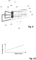
- Fig. 6 shows another position measuring system 200.
- the system 200 includes a magnetic angle sensor 205, a top collector 210, an upper-middle collector 215, a lower-middle collector 220, a bottom collector 225, and a magnet 230.
- the collectors 210, 215, 220, and 225 are positioned parallel to one another and angled relative to the magnet 230.
- the collectors 210, 215, 220, and 225 and magnetic circuit elements 235 are made from a material with a relatively high permeability.
- the magnet 230 is a permanent magnet having a single pole pair - a north pole 240 and a south pole 245.
- the magnet 230 may be a magnet assembly, including magnets and/or pole pieces.
- the magnet 230 travels perpendicular to the length of the magnet 230, parallel to and a fixed distance from the plane of the collectors 210, 215, 220, and 225. Arrows 250 indicate the directions of travel of the magnet 230.
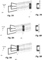
- the magnetic angle sensor 205 detects a first flux angle 265 (e.g., 270°).
- the magnetic angle sensor 205 detects a second flux angle 275 (e.g., 225° or about 45° from the first flux angle 265) (see Fig. 8A ).
- the magnetic angle sensor 205 detects a third flux angle 285 (e.g., 180° or about 90° from the first flux angle 265) (see Fig. 9A ).
- Figs. 7B, 8B, and 9B show a position of a u-shaped magnet 205 relative to the collectors 210, 215, 220, and 225 at the first end 260, the center 270, and the second end 280, respectively.
- the magnet 230 When the magnet 230 is positioned at the first end 260 (e.g., Figs. 7A and 7B ), the magnetic flux travels from the upper-middle collector 215 to the bottom collector 225.
- the magnetic flux travels over multiple paths (e.g., from the top collector 210 and the upper-middle collector 215 to the lower-middle collector 220 and the bottom collector 225).
- Fig. 10 shows a graph of a possible output of the magnetic angle sensor 205 based on the position of the magnet 230.
- a monotonic shifting of the flux angle at the sensor 205 occurs as the magnet 230 changes position. If the gap between the magnet 230 and the collectors 210, 215, 220, and 225 changes, the measured angle does not change significantly. The magnitude of the flux density at the sensor 205 may change, but the ratio of the flux traveling down each magnetic circuit path stays approximately the same. It is generally believed that the monotonic shifting of the angle in the measuring system 200 provides a more accurate determination of magnet position than the position measuring system 100.
- Figs. 11A and 11B show yet another position measuring system 400.
- the system 400 includes a common collector 405, a first collector 410, a second collector 415, a first magnetic sensor 420 (coupled to the first collector 410), a second magnetic sensor 425 (coupled to the second collector 415), a magnet 430, and magnetic circuit elements 435.
- the first and second collectors 410 and 415, the magnet 430, the sensors 420 and 425, and the magnetic circuit elements 435 are positioned relative to each other as shown in the figures.
- the sensors 420 and 425 are located in the vicinity (i.e., near) of the collectors 410 and 415, respectively.
- the common collector 405 includes a lowered element 440 that is angled (i.e., a magnetic feature) such that at a first end 450 of the lowered element 440 shares an axis 455 with the first collector 410, and a second end 460 of the lowered element 440 shares an axis 465 with the second collector 415.
- the common collector 405 moves in the directions shown by the arrows 470.
- a magnetic coupling with the first collector 410 occurs.
- the common collector 405 travels to a second end of its range of travel (see Fig. 12B )
- the magnetic coupling switches from the first collector 410 to the second collector 415.
- Fig. 13 shows a graph of a ratio of the possible outputs of the magnetic sensors 420 and 425 based on the position of the common collector 405.
- Figs. 14A and 14B show another position measuring system 500.
- the system 500 includes a common collector 505, a first collector 510, a second collector 515, a magnetic angle sensor 520, a magnet 530, and magnetic circuit elements 535.
- the first and second collectors 510 and 515, the magnet 530, the sensor 520, and the magnetic circuit elements 535 are positioned relative to each other as shown.
- the common collector 505 includes a lowered element 550 that is angled the same as common collector 405. As common collector 505 moves through its range of motion, a flux angle detected by the magnetic angle sensor 520 changes as discussed above with respect to previous embodiments.
- the common collectors 405/505 can be a stamped piece of material, and have a relatively high magnetic permeability and a relatively low magnetic hysteresis.
- the magnet can be a permanent magnet (e.g., a ferrite, an alnico, a samarium-cobalt, a neodymium-iron-boron, or other type of magnet). It is also possible for the magnet to be an active magnetic field generator, like an electro-magnet, although in most applications a permanent magnet will be selected because of the lower system cost.
- a permanent magnet e.g., a ferrite, an alnico, a samarium-cobalt, a neodymium-iron-boron, or other type of magnet.
- an active magnetic field generator like an electro-magnet
- the magnets have a simple shape. However, it is also possible to use magnets of other shapes to improve performance or meet packaging constraints. As an example, the magnets could take on a "U" shape to better direct the flux lines to the collectors. In addition, the magnets could take on a shape to reduce the influence of movement in the direction orthogonal to the movement the system is trying to measure. For example the magnet poles could be wider or narrower than the collectors so that movement "up” or “down” would have a much smaller influence on the coupling between the magnet poles and the relevant collector. In addition, the magnets in this description may include pole pieces as part of a magnet assembly.
- the collectors are held in place with mechanical constraints.
- the components could be held in place with over-molded plastic supports or with potting.
- the sensors are held in place relative to the magnetic circuit elements and the magnetic flux concentrators directing the flux to the sensor(s).
- the senor itself is preferably a Hall Effect sensor or other magnetic sensor that can measure flux density.
- the sensor can be a magnetoresistive sensor (e.g., AMR, GMR, and TMR) or a Hall-based angle sensor.
- AMR magnetoresistive sensor
- GMR GMR
- TMR Hall-based angle sensor
- multiple Hall sensors in a single device are used to collectively measure the angle of the magnetic flux.
- Other technologies that can measure flux angle can also be used.
- Commercially available sensors e.g., from Allegro, Micronas, Infineon, NXP, and others) can be used in the embodiments described above.
- the collectors and magnetic circuit elements are depicted above as simple shapes, but they could be complex 3-dimensonal shapes.
- the collector could be relatively flat with a tab coming out of one edge (top edge, bottom edge, or side edges), perpendicular to the collector, and eventually leading to the sensor area.
- the magnetic circuit elements leading to the sensor(s) could be any shape and connected anywhere on the collectors. Effectively, the magnetic circuit elements are a part of the respective magnetic collectors.
- the sensor could be placed directly next to the collector such that there is no identifiable magnetic circuit element coming from the collector. Those knowledgeable in the art will recognize that this does not change the concepts within this invention.
- the flux collector and magnetic circuit elements are designed to be compatible with the flux densities expected within the application.
- the design considers the flux level at which the collector or the magnetic circuit element may saturate. Saturation causes the magnetic circuit reluctance to change and will, as a consequence, change the measurement from the expected measurement for the magnet's position.
- orientation of the magnet (distance between the collectors and the magnet) and the relative orientation of the magnet with respect to the collectors can also be modified.
- collectors that follow the path of a magnet when the magnet does not travel in a straight line.
- the collectors could be designed to fit along the inside or outside of the curve and, as long as the distance between the magnet and the collectors is approximately constant, the output signal (ratio or angle) would vary continuously with the magnet position.
Landscapes
- Physics & Mathematics (AREA)
- General Physics & Mathematics (AREA)
- Transmission And Conversion Of Sensor Element Output (AREA)
- Measurement Of Length, Angles, Or The Like Using Electric Or Magnetic Means (AREA)
Claims (3)
- Ein magnetisch basierter Positionssensor (100; 200), umfassend:- ein Magnetaufbau (120; 230), der sich entlang eines Pfades (140; 250) bewegt;- wenigstens zwei magnetische Kollektoren (110, 115; 210, 225), die voneinander mit einem Luftspalt zwischen den beiden magnetischen Kollektoren (110, 115; 210, 225), die parallel zueinander und in einem Winkel relativ zur Achse (122) des Pfades (140, 250) angeordnet sind, beabstandet sind, wobei der Luftspalt wenigstens teilweise vom Magnetaufbau (120, 230) gekreuzt ist, wenn sich der Magnetaufbau (120, 230) entlang des Pfades (140, 250) bewegt;- ein magnetischer Sensor (105, 205), der an die wenigstens zwei magnetischen Kollektoren (110, 115; 210, 225) angeschlossen ist;- wobei der magnetische Sensor (105; 205) ein Signal erzeugt, das sich auf die Position des Magnetaufbaus (120; 230) bezieht, wenn sich der Magnetaufbau (120; 230) entlang des Pfades (140; 250) bewegt,
dadurch gekennzeichnet, dass- der Magnetaufbau (120; 230) wenigstens zwei Pole (N, S) und eine durch die Pole (N, S) gesehene Länge besitzt, die rechtwinklig oder geneigt zum Pfad (140; 250) ist. - Der Sensor (100; 200) nach Anspruch 1, wobei der magnetische Sensor (105, 205) die Flussdichte oder den Flusswinkel an einer Stelle zwischen den magnetischen Kollektoren (110, 115; 210, 225) misst.
- Der Sensor (100; 200) nach Anspruch 1, wobei eine Ebene der Kollektoren (110, 115; 210, 215) und der Pfad (140; 250) des Magnetaufbaus (120; 230) parallel sind.
Priority Applications (1)
| Application Number | Priority Date | Filing Date | Title |
|---|---|---|---|
| EP18172018.6A EP3489628A1 (de) | 2013-03-15 | 2014-03-10 | Positionsmessung mithilfe von abgewinkelten kollektoren |
Applications Claiming Priority (2)
| Application Number | Priority Date | Filing Date | Title |
|---|---|---|---|
| US13/835,273 US9772200B2 (en) | 2013-03-15 | 2013-03-15 | Position measurement using angled collectors |
| PCT/US2014/022819 WO2014150281A1 (en) | 2013-03-15 | 2014-03-10 | Position measurement using angled collectors |
Related Child Applications (2)
| Application Number | Title | Priority Date | Filing Date |
|---|---|---|---|
| EP18172018.6A Division EP3489628A1 (de) | 2013-03-15 | 2014-03-10 | Positionsmessung mithilfe von abgewinkelten kollektoren |
| EP18172018.6A Division-Into EP3489628A1 (de) | 2013-03-15 | 2014-03-10 | Positionsmessung mithilfe von abgewinkelten kollektoren |
Publications (3)
| Publication Number | Publication Date |
|---|---|
| EP2972067A1 EP2972067A1 (de) | 2016-01-20 |
| EP2972067A4 EP2972067A4 (de) | 2017-02-15 |
| EP2972067B1 true EP2972067B1 (de) | 2018-07-18 |
Family
ID=51524743
Family Applications (2)
| Application Number | Title | Priority Date | Filing Date |
|---|---|---|---|
| EP14769448.3A Active EP2972067B1 (de) | 2013-03-15 | 2014-03-10 | Positionsmessung mit abgewinkelten kollektoren |
| EP18172018.6A Withdrawn EP3489628A1 (de) | 2013-03-15 | 2014-03-10 | Positionsmessung mithilfe von abgewinkelten kollektoren |
Family Applications After (1)
| Application Number | Title | Priority Date | Filing Date |
|---|---|---|---|
| EP18172018.6A Withdrawn EP3489628A1 (de) | 2013-03-15 | 2014-03-10 | Positionsmessung mithilfe von abgewinkelten kollektoren |
Country Status (7)
| Country | Link |
|---|---|
| US (1) | US9772200B2 (de) |
| EP (2) | EP2972067B1 (de) |
| JP (1) | JP6397475B2 (de) |
| KR (1) | KR102079417B1 (de) |
| CN (1) | CN105051483B (de) |
| HU (1) | HUE039716T2 (de) |
| WO (1) | WO2014150281A1 (de) |
Families Citing this family (4)
| Publication number | Priority date | Publication date | Assignee | Title |
|---|---|---|---|---|
| US9018942B2 (en) * | 2013-01-11 | 2015-04-28 | Bourns, Inc. | Position measurement using a variable flux collector |
| US20230258745A1 (en) * | 2020-06-24 | 2023-08-17 | Motus Labs, LLC | Magnetic Field Detection Apparatus, System, and Method |
| CN111998760B (zh) * | 2020-07-07 | 2021-11-16 | 安徽博昕远智能科技有限公司 | 一种用于检测车身位移的传感器和方法 |
| WO2022039386A1 (ko) * | 2020-08-20 | 2022-02-24 | 엘지이노텍 주식회사 | 센싱 장치 |
Family Cites Families (36)
| Publication number | Priority date | Publication date | Assignee | Title |
|---|---|---|---|---|
| DE1440193B2 (de) | 1961-09-05 | 1972-01-13 | Siemens AG, 1000 Berlin u 8000 München | Magnetisch elektrischer signalgeber mit einem hallgenerator |
| JPS54160156U (de) * | 1978-04-28 | 1979-11-08 | ||
| JPS56118613A (en) * | 1980-02-22 | 1981-09-17 | Sony Corp | Magnetoelectric transducer |
| JPS56153204A (en) * | 1980-04-28 | 1981-11-27 | Nec Home Electronics Ltd | Detector for rotating angle |
| JPS5847710U (ja) * | 1981-09-28 | 1983-03-31 | 日本電気ホームエレクトロニクス株式会社 | 回転角検出装置 |
| DD257178A3 (de) * | 1985-09-27 | 1988-06-08 | Hermsdorf Keramik Veb | Anordnung zur erzeugung von steuersignalen |
| US4841246A (en) * | 1987-12-29 | 1989-06-20 | Eaton Corporation | Multiturn shaft position sensor having magnet movable with nonrotating linear moving nut |
| US5570015A (en) * | 1992-02-05 | 1996-10-29 | Mitsubishi Denki Kabushiki Kaisha | Linear positional displacement detector for detecting linear displacement of a permanent magnet as a change in direction of magnetic sensor unit |
| EP0559265B1 (de) * | 1992-02-27 | 1997-05-14 | Koninklijke Philips Electronics N.V. | Positionssensorsystem |
| JP3296871B2 (ja) | 1993-02-05 | 2002-07-02 | 浜松光電株式会社 | 無接触式直線変位センサ |
| US5600238A (en) * | 1994-07-05 | 1997-02-04 | Ford Motor Company | Method and apparatus for detecting the linear or rotary position of an object through the use of a variable magnetic shunt disposed in parallel with a yoke air gap |
| US5719496A (en) * | 1995-06-07 | 1998-02-17 | Durakool Incorporated | Dual-element proximity sensor for sensing the direction of rotation of a ferrous target wheel |
| US5781005A (en) * | 1995-06-07 | 1998-07-14 | Allegro Microsystems, Inc. | Hall-effect ferromagnetic-article-proximity sensor |
| FR2764372B1 (fr) * | 1997-06-04 | 1999-09-24 | Moving Magnet Tech | Capteur magnetique de position |
| JP3272662B2 (ja) * | 1998-03-30 | 2002-04-08 | 太陽鉄工株式会社 | 位置検知装置 |
| WO2000062031A1 (en) | 1999-04-07 | 2000-10-19 | Koyo Seiko Co., Ltd. | Rotation angle detector, torque detector and steering device |
| JP4038308B2 (ja) * | 1999-09-09 | 2008-01-23 | 株式会社ミクニ | 非接触式ポジションセンサ |
| US6577119B1 (en) * | 1999-12-01 | 2003-06-10 | Sena Yaddehige | Pedal position sensor with magnet movable relative to a magnetic field sensor located in a stator channel |
| DE10009173A1 (de) * | 2000-02-26 | 2001-09-06 | Bosch Gmbh Robert | Messvorrichtung zur berührungslosen Erfassung eines ferromagnetischen Gegenstandes |
| EP1328771A4 (de) * | 2000-09-29 | 2005-09-14 | Stoneridge Control Devices Inc | Linearpositionssensor |
| JP4154922B2 (ja) * | 2001-05-11 | 2008-09-24 | 三菱電機株式会社 | 位置検出装置 |
| JP3842644B2 (ja) | 2001-11-19 | 2006-11-08 | 株式会社日本自動車部品総合研究所 | 変位量センサ |
| AU2003206627B2 (en) * | 2002-01-23 | 2007-12-13 | Robert Bosch Gmbh | Path sensor with an magnetoelectric transformer element |
| DE10258254A1 (de) * | 2002-01-23 | 2003-07-31 | Bosch Gmbh Robert | Wegsensor mit magnetoelektrischem Wandlerelement |
| JP4446377B2 (ja) * | 2004-04-08 | 2010-04-07 | 株式会社小松製作所 | 変位センサ |
| US7242183B2 (en) * | 2005-02-28 | 2007-07-10 | Delphi Technologies, Inc. | Low cost linear position sensor employing one permanent magnat and one galvanomagnetic sensing element |
| JP4720233B2 (ja) * | 2005-03-18 | 2011-07-13 | 株式会社デンソー | 回転角度検出装置 |
| US7116100B1 (en) | 2005-03-21 | 2006-10-03 | Hr Textron, Inc. | Position sensing for moveable mechanical systems and associated methods and apparatus |
| US7302940B2 (en) * | 2005-09-26 | 2007-12-04 | Cummins, Inc | Variable reluctance position sensor |
| WO2007069680A1 (ja) * | 2005-12-16 | 2007-06-21 | Asahi Kasei Emd Corporation | 位置検出装置 |
| FR2937722B1 (fr) | 2008-10-24 | 2010-11-26 | Moving Magnet Tech Mmt | Capteur de position magnetique a mesure de direction de champ et a collecteur de flux |
| DE102009012794B3 (de) * | 2009-03-13 | 2010-11-11 | Vacuumschmelze Gmbh & Co. Kg | Hysteresearmer Sensor |
| US8087305B2 (en) | 2009-05-15 | 2012-01-03 | Infineon Technologies Ag | System including a magnet and first and second concentrators |
| DE102010019077A1 (de) * | 2010-04-30 | 2011-11-03 | Continental Automotive Gmbh | Magnetisches Längenmesssystem, Längenmessverfahren sowie Herstellungsverfahren eines magnetischen Längenmesssystems |
| US9371064B2 (en) * | 2010-06-30 | 2016-06-21 | Kelsey-Hayes Company | Position sensing assembly for use with a vehicle hydraulic master cylinder of a vehicle braking system with master cylinder assembly including such a position sensing assembly |
| JP5434939B2 (ja) * | 2011-03-16 | 2014-03-05 | 株式会社デンソー | ストローク量検出装置 |
-
2013
- 2013-03-15 US US13/835,273 patent/US9772200B2/en active Active
-
2014
- 2014-03-10 WO PCT/US2014/022819 patent/WO2014150281A1/en not_active Ceased
- 2014-03-10 HU HUE14769448A patent/HUE039716T2/hu unknown
- 2014-03-10 KR KR1020157024924A patent/KR102079417B1/ko active Active
- 2014-03-10 EP EP14769448.3A patent/EP2972067B1/de active Active
- 2014-03-10 EP EP18172018.6A patent/EP3489628A1/de not_active Withdrawn
- 2014-03-10 JP JP2016501079A patent/JP6397475B2/ja active Active
- 2014-03-10 CN CN201480016034.8A patent/CN105051483B/zh active Active
Non-Patent Citations (1)
| Title |
|---|
| None * |
Also Published As
| Publication number | Publication date |
|---|---|
| US20140266157A1 (en) | 2014-09-18 |
| US9772200B2 (en) | 2017-09-26 |
| CN105051483B (zh) | 2018-01-23 |
| EP2972067A1 (de) | 2016-01-20 |
| JP6397475B2 (ja) | 2018-09-26 |
| WO2014150281A1 (en) | 2014-09-25 |
| JP2016511416A (ja) | 2016-04-14 |
| KR102079417B1 (ko) | 2020-02-19 |
| CN105051483A (zh) | 2015-11-11 |
| EP3489628A1 (de) | 2019-05-29 |
| KR20150130295A (ko) | 2015-11-23 |
| EP2972067A4 (de) | 2017-02-15 |
| HUE039716T2 (hu) | 2019-01-28 |
Similar Documents
| Publication | Publication Date | Title |
|---|---|---|
| US9244135B2 (en) | Magnetic sensor device | |
| EP3084456B1 (de) | Magnetfeldsensor und verfahren zum abtasten des relativen standorts des magnetfeldsensors und eines zielobjekts entlang einer bewegungslinie | |
| US9435829B2 (en) | Current sensor | |
| US9018942B2 (en) | Position measurement using a variable flux collector | |
| US8878520B2 (en) | Current sensor | |
| EP2728302B1 (de) | Näherungssensor | |
| EP2972067B1 (de) | Positionsmessung mit abgewinkelten kollektoren | |
| US9645203B2 (en) | Magnetic field measuring device | |
| US11585676B2 (en) | Magnetic field measuring device | |
| CN108692648B (zh) | 用于非接触线性位置检测的传感器装置 | |
| JP2012098190A (ja) | 直線変位検出装置 | |
| JP5409972B2 (ja) | 位置検出装置 | |
| US11181394B2 (en) | Distance measuring device | |
| JP2013200301A (ja) | 電流センサ | |
| JP5875947B2 (ja) | 磁気センサ装置 | |
| CN106716070A (zh) | 位置检测装置以及位置检测装置的使用结构 | |
| JP2013142569A (ja) | 電流センサ | |
| JP2014102181A (ja) | 磁気センサ | |
| JPWO2015019534A1 (ja) | 磁気センサおよびこの磁気センサを用いた電流センサ | |
| JP2015031647A (ja) | 電流センサおよびその製造方法 | |
| JP2017106825A (ja) | 磁気検出装置 | |
| JP2013088171A (ja) | 位置検出装置 |
Legal Events
| Date | Code | Title | Description |
|---|---|---|---|
| PUAI | Public reference made under article 153(3) epc to a published international application that has entered the european phase |
Free format text: ORIGINAL CODE: 0009012 |
|
| 17P | Request for examination filed |
Effective date: 20151015 |
|
| AK | Designated contracting states |
Kind code of ref document: A1 Designated state(s): AL AT BE BG CH CY CZ DE DK EE ES FI FR GB GR HR HU IE IS IT LI LT LU LV MC MK MT NL NO PL PT RO RS SE SI SK SM TR |
|
| AX | Request for extension of the european patent |
Extension state: BA ME |
|
| DAX | Request for extension of the european patent (deleted) | ||
| REG | Reference to a national code |
Ref country code: DE Ref legal event code: R079 Ref document number: 602014028764 Country of ref document: DE Free format text: PREVIOUS MAIN CLASS: G01B0007140000 Ipc: G01D0005140000 |
|
| A4 | Supplementary search report drawn up and despatched |
Effective date: 20170116 |
|
| RIC1 | Information provided on ipc code assigned before grant |
Ipc: G01D 5/14 20060101AFI20170110BHEP |
|
| GRAP | Despatch of communication of intention to grant a patent |
Free format text: ORIGINAL CODE: EPIDOSNIGR1 |
|
| STAA | Information on the status of an ep patent application or granted ep patent |
Free format text: STATUS: GRANT OF PATENT IS INTENDED |
|
| INTG | Intention to grant announced |
Effective date: 20180214 |
|
| GRAS | Grant fee paid |
Free format text: ORIGINAL CODE: EPIDOSNIGR3 |
|
| GRAA | (expected) grant |
Free format text: ORIGINAL CODE: 0009210 |
|
| STAA | Information on the status of an ep patent application or granted ep patent |
Free format text: STATUS: THE PATENT HAS BEEN GRANTED |
|
| AK | Designated contracting states |
Kind code of ref document: B1 Designated state(s): AL AT BE BG CH CY CZ DE DK EE ES FI FR GB GR HR HU IE IS IT LI LT LU LV MC MK MT NL NO PL PT RO RS SE SI SK SM TR |
|
| REG | Reference to a national code |
Ref country code: GB Ref legal event code: FG4D |
|
| REG | Reference to a national code |
Ref country code: CH Ref legal event code: EP |
|
| REG | Reference to a national code |
Ref country code: IE Ref legal event code: FG4D |
|
| REG | Reference to a national code |
Ref country code: AT Ref legal event code: REF Ref document number: 1019870 Country of ref document: AT Kind code of ref document: T Effective date: 20180815 |
|
| REG | Reference to a national code |
Ref country code: DE Ref legal event code: R096 Ref document number: 602014028764 Country of ref document: DE |
|
| REG | Reference to a national code |
Ref country code: NL Ref legal event code: MP Effective date: 20180718 |
|
| REG | Reference to a national code |
Ref country code: LT Ref legal event code: MG4D |
|
| REG | Reference to a national code |
Ref country code: AT Ref legal event code: MK05 Ref document number: 1019870 Country of ref document: AT Kind code of ref document: T Effective date: 20180718 |
|
| PG25 | Lapsed in a contracting state [announced via postgrant information from national office to epo] |
Ref country code: NL Free format text: LAPSE BECAUSE OF FAILURE TO SUBMIT A TRANSLATION OF THE DESCRIPTION OR TO PAY THE FEE WITHIN THE PRESCRIBED TIME-LIMIT Effective date: 20180718 |
|
| REG | Reference to a national code |
Ref country code: HU Ref legal event code: AG4A Ref document number: E039716 Country of ref document: HU |
|
| PG25 | Lapsed in a contracting state [announced via postgrant information from national office to epo] |
Ref country code: FI Free format text: LAPSE BECAUSE OF FAILURE TO SUBMIT A TRANSLATION OF THE DESCRIPTION OR TO PAY THE FEE WITHIN THE PRESCRIBED TIME-LIMIT Effective date: 20180718 Ref country code: GR Free format text: LAPSE BECAUSE OF FAILURE TO SUBMIT A TRANSLATION OF THE DESCRIPTION OR TO PAY THE FEE WITHIN THE PRESCRIBED TIME-LIMIT Effective date: 20181019 Ref country code: NO Free format text: LAPSE BECAUSE OF FAILURE TO SUBMIT A TRANSLATION OF THE DESCRIPTION OR TO PAY THE FEE WITHIN THE PRESCRIBED TIME-LIMIT Effective date: 20181018 Ref country code: IS Free format text: LAPSE BECAUSE OF FAILURE TO SUBMIT A TRANSLATION OF THE DESCRIPTION OR TO PAY THE FEE WITHIN THE PRESCRIBED TIME-LIMIT Effective date: 20181118 Ref country code: AT Free format text: LAPSE BECAUSE OF FAILURE TO SUBMIT A TRANSLATION OF THE DESCRIPTION OR TO PAY THE FEE WITHIN THE PRESCRIBED TIME-LIMIT Effective date: 20180718 Ref country code: LT Free format text: LAPSE BECAUSE OF FAILURE TO SUBMIT A TRANSLATION OF THE DESCRIPTION OR TO PAY THE FEE WITHIN THE PRESCRIBED TIME-LIMIT Effective date: 20180718 Ref country code: RS Free format text: LAPSE BECAUSE OF FAILURE TO SUBMIT A TRANSLATION OF THE DESCRIPTION OR TO PAY THE FEE WITHIN THE PRESCRIBED TIME-LIMIT Effective date: 20180718 Ref country code: SE Free format text: LAPSE BECAUSE OF FAILURE TO SUBMIT A TRANSLATION OF THE DESCRIPTION OR TO PAY THE FEE WITHIN THE PRESCRIBED TIME-LIMIT Effective date: 20180718 Ref country code: BG Free format text: LAPSE BECAUSE OF FAILURE TO SUBMIT A TRANSLATION OF THE DESCRIPTION OR TO PAY THE FEE WITHIN THE PRESCRIBED TIME-LIMIT Effective date: 20181018 Ref country code: PL Free format text: LAPSE BECAUSE OF FAILURE TO SUBMIT A TRANSLATION OF THE DESCRIPTION OR TO PAY THE FEE WITHIN THE PRESCRIBED TIME-LIMIT Effective date: 20180718 |
|
| PG25 | Lapsed in a contracting state [announced via postgrant information from national office to epo] |
Ref country code: AL Free format text: LAPSE BECAUSE OF FAILURE TO SUBMIT A TRANSLATION OF THE DESCRIPTION OR TO PAY THE FEE WITHIN THE PRESCRIBED TIME-LIMIT Effective date: 20180718 Ref country code: LV Free format text: LAPSE BECAUSE OF FAILURE TO SUBMIT A TRANSLATION OF THE DESCRIPTION OR TO PAY THE FEE WITHIN THE PRESCRIBED TIME-LIMIT Effective date: 20180718 Ref country code: HR Free format text: LAPSE BECAUSE OF FAILURE TO SUBMIT A TRANSLATION OF THE DESCRIPTION OR TO PAY THE FEE WITHIN THE PRESCRIBED TIME-LIMIT Effective date: 20180718 |
|
| REG | Reference to a national code |
Ref country code: DE Ref legal event code: R097 Ref document number: 602014028764 Country of ref document: DE |
|
| PG25 | Lapsed in a contracting state [announced via postgrant information from national office to epo] |
Ref country code: ES Free format text: LAPSE BECAUSE OF FAILURE TO SUBMIT A TRANSLATION OF THE DESCRIPTION OR TO PAY THE FEE WITHIN THE PRESCRIBED TIME-LIMIT Effective date: 20180718 Ref country code: RO Free format text: LAPSE BECAUSE OF FAILURE TO SUBMIT A TRANSLATION OF THE DESCRIPTION OR TO PAY THE FEE WITHIN THE PRESCRIBED TIME-LIMIT Effective date: 20180718 Ref country code: CZ Free format text: LAPSE BECAUSE OF FAILURE TO SUBMIT A TRANSLATION OF THE DESCRIPTION OR TO PAY THE FEE WITHIN THE PRESCRIBED TIME-LIMIT Effective date: 20180718 Ref country code: EE Free format text: LAPSE BECAUSE OF FAILURE TO SUBMIT A TRANSLATION OF THE DESCRIPTION OR TO PAY THE FEE WITHIN THE PRESCRIBED TIME-LIMIT Effective date: 20180718 |
|
| PLBE | No opposition filed within time limit |
Free format text: ORIGINAL CODE: 0009261 |
|
| STAA | Information on the status of an ep patent application or granted ep patent |
Free format text: STATUS: NO OPPOSITION FILED WITHIN TIME LIMIT |
|
| PG25 | Lapsed in a contracting state [announced via postgrant information from national office to epo] |
Ref country code: DK Free format text: LAPSE BECAUSE OF FAILURE TO SUBMIT A TRANSLATION OF THE DESCRIPTION OR TO PAY THE FEE WITHIN THE PRESCRIBED TIME-LIMIT Effective date: 20180718 Ref country code: SM Free format text: LAPSE BECAUSE OF FAILURE TO SUBMIT A TRANSLATION OF THE DESCRIPTION OR TO PAY THE FEE WITHIN THE PRESCRIBED TIME-LIMIT Effective date: 20180718 Ref country code: SK Free format text: LAPSE BECAUSE OF FAILURE TO SUBMIT A TRANSLATION OF THE DESCRIPTION OR TO PAY THE FEE WITHIN THE PRESCRIBED TIME-LIMIT Effective date: 20180718 |
|
| 26N | No opposition filed |
Effective date: 20190423 |
|
| PG25 | Lapsed in a contracting state [announced via postgrant information from national office to epo] |
Ref country code: SI Free format text: LAPSE BECAUSE OF FAILURE TO SUBMIT A TRANSLATION OF THE DESCRIPTION OR TO PAY THE FEE WITHIN THE PRESCRIBED TIME-LIMIT Effective date: 20180718 |
|
| PG25 | Lapsed in a contracting state [announced via postgrant information from national office to epo] |
Ref country code: MC Free format text: LAPSE BECAUSE OF FAILURE TO SUBMIT A TRANSLATION OF THE DESCRIPTION OR TO PAY THE FEE WITHIN THE PRESCRIBED TIME-LIMIT Effective date: 20180718 |
|
| REG | Reference to a national code |
Ref country code: CH Ref legal event code: PL |
|
| PG25 | Lapsed in a contracting state [announced via postgrant information from national office to epo] |
Ref country code: LU Free format text: LAPSE BECAUSE OF NON-PAYMENT OF DUE FEES Effective date: 20190310 |
|
| REG | Reference to a national code |
Ref country code: BE Ref legal event code: MM Effective date: 20190331 |
|
| PG25 | Lapsed in a contracting state [announced via postgrant information from national office to epo] |
Ref country code: LI Free format text: LAPSE BECAUSE OF NON-PAYMENT OF DUE FEES Effective date: 20190331 Ref country code: IE Free format text: LAPSE BECAUSE OF NON-PAYMENT OF DUE FEES Effective date: 20190310 Ref country code: CH Free format text: LAPSE BECAUSE OF NON-PAYMENT OF DUE FEES Effective date: 20190331 |
|
| PG25 | Lapsed in a contracting state [announced via postgrant information from national office to epo] |
Ref country code: BE Free format text: LAPSE BECAUSE OF NON-PAYMENT OF DUE FEES Effective date: 20190331 |
|
| PG25 | Lapsed in a contracting state [announced via postgrant information from national office to epo] |
Ref country code: TR Free format text: LAPSE BECAUSE OF FAILURE TO SUBMIT A TRANSLATION OF THE DESCRIPTION OR TO PAY THE FEE WITHIN THE PRESCRIBED TIME-LIMIT Effective date: 20180718 |
|
| PG25 | Lapsed in a contracting state [announced via postgrant information from national office to epo] |
Ref country code: PT Free format text: LAPSE BECAUSE OF FAILURE TO SUBMIT A TRANSLATION OF THE DESCRIPTION OR TO PAY THE FEE WITHIN THE PRESCRIBED TIME-LIMIT Effective date: 20181118 Ref country code: MT Free format text: LAPSE BECAUSE OF NON-PAYMENT OF DUE FEES Effective date: 20190310 |
|
| PG25 | Lapsed in a contracting state [announced via postgrant information from national office to epo] |
Ref country code: CY Free format text: LAPSE BECAUSE OF FAILURE TO SUBMIT A TRANSLATION OF THE DESCRIPTION OR TO PAY THE FEE WITHIN THE PRESCRIBED TIME-LIMIT Effective date: 20180718 |
|
| PG25 | Lapsed in a contracting state [announced via postgrant information from national office to epo] |
Ref country code: MK Free format text: LAPSE BECAUSE OF FAILURE TO SUBMIT A TRANSLATION OF THE DESCRIPTION OR TO PAY THE FEE WITHIN THE PRESCRIBED TIME-LIMIT Effective date: 20180718 |
|
| P01 | Opt-out of the competence of the unified patent court (upc) registered |
Effective date: 20230514 |
|
| PGFP | Annual fee paid to national office [announced via postgrant information from national office to epo] |
Ref country code: GB Payment date: 20260227 Year of fee payment: 13 |
|
| PGFP | Annual fee paid to national office [announced via postgrant information from national office to epo] |
Ref country code: DE Payment date: 20260317 Year of fee payment: 13 |
|
| PGFP | Annual fee paid to national office [announced via postgrant information from national office to epo] |
Ref country code: IT Payment date: 20260319 Year of fee payment: 13 |
|
| PGFP | Annual fee paid to national office [announced via postgrant information from national office to epo] |
Ref country code: HU Payment date: 20260225 Year of fee payment: 13 |
|
| PGFP | Annual fee paid to national office [announced via postgrant information from national office to epo] |
Ref country code: FR Payment date: 20260311 Year of fee payment: 13 |