EP2972146B1 - Vibrationsanalysator für fahrzeugdiagnostik - Google Patents
Vibrationsanalysator für fahrzeugdiagnostik Download PDFInfo
- Publication number
- EP2972146B1 EP2972146B1 EP14763407.5A EP14763407A EP2972146B1 EP 2972146 B1 EP2972146 B1 EP 2972146B1 EP 14763407 A EP14763407 A EP 14763407A EP 2972146 B1 EP2972146 B1 EP 2972146B1
- Authority
- EP
- European Patent Office
- Prior art keywords
- vibration
- analyzer
- vehicle
- vibration analyzer
- data
- Prior art date
- Legal status (The legal status is an assumption and is not a legal conclusion. Google has not performed a legal analysis and makes no representation as to the accuracy of the status listed.)
- Active
Links
- 238000000034 method Methods 0.000 claims description 10
- 238000012360 testing method Methods 0.000 claims description 10
- 238000001514 detection method Methods 0.000 claims description 3
- 230000006870 function Effects 0.000 claims description 3
- 238000007493 shaping process Methods 0.000 claims 1
- 238000004891 communication Methods 0.000 description 11
- 238000004458 analytical method Methods 0.000 description 4
- 238000010586 diagram Methods 0.000 description 4
- 239000000853 adhesive Substances 0.000 description 3
- 230000001070 adhesive effect Effects 0.000 description 3
- 239000003292 glue Substances 0.000 description 3
- -1 Nickel Metal Hydride Chemical class 0.000 description 2
- 238000010276 construction Methods 0.000 description 2
- 230000001419 dependent effect Effects 0.000 description 2
- 238000003745 diagnosis Methods 0.000 description 2
- 239000000463 material Substances 0.000 description 2
- 229910052759 nickel Inorganic materials 0.000 description 2
- PXHVJJICTQNCMI-UHFFFAOYSA-N nickel Substances [Ni] PXHVJJICTQNCMI-UHFFFAOYSA-N 0.000 description 2
- WHXSMMKQMYFTQS-UHFFFAOYSA-N Lithium Chemical compound [Li] WHXSMMKQMYFTQS-UHFFFAOYSA-N 0.000 description 1
- HBBGRARXTFLTSG-UHFFFAOYSA-N Lithium ion Chemical compound [Li+] HBBGRARXTFLTSG-UHFFFAOYSA-N 0.000 description 1
- 230000001133 acceleration Effects 0.000 description 1
- 238000003491 array Methods 0.000 description 1
- OJIJEKBXJYRIBZ-UHFFFAOYSA-N cadmium nickel Chemical compound [Ni].[Cd] OJIJEKBXJYRIBZ-UHFFFAOYSA-N 0.000 description 1
- 230000001413 cellular effect Effects 0.000 description 1
- 230000008878 coupling Effects 0.000 description 1
- 238000010168 coupling process Methods 0.000 description 1
- 238000005859 coupling reaction Methods 0.000 description 1
- 238000007405 data analysis Methods 0.000 description 1
- 230000007423 decrease Effects 0.000 description 1
- 238000011156 evaluation Methods 0.000 description 1
- 239000011888 foil Substances 0.000 description 1
- 229910052739 hydrogen Inorganic materials 0.000 description 1
- 239000001257 hydrogen Substances 0.000 description 1
- 229910052744 lithium Inorganic materials 0.000 description 1
- 229910001416 lithium ion Inorganic materials 0.000 description 1
- 229910052987 metal hydride Inorganic materials 0.000 description 1
- 238000012544 monitoring process Methods 0.000 description 1
- 229920000642 polymer Polymers 0.000 description 1
- 230000002028 premature Effects 0.000 description 1
- 230000008439 repair process Effects 0.000 description 1
- 230000035945 sensitivity Effects 0.000 description 1
- 230000035939 shock Effects 0.000 description 1
- 229920001169 thermoplastic Polymers 0.000 description 1
- 239000004416 thermosoftening plastic Substances 0.000 description 1
- 238000012795 verification Methods 0.000 description 1
Images

Classifications
-
- G—PHYSICS
- G01—MEASURING; TESTING
- G01M—TESTING STATIC OR DYNAMIC BALANCE OF MACHINES OR STRUCTURES; TESTING OF STRUCTURES OR APPARATUS, NOT OTHERWISE PROVIDED FOR
- G01M7/00—Vibration-testing of structures; Shock-testing of structures
-
- G—PHYSICS
- G07—CHECKING-DEVICES
- G07C—TIME OR ATTENDANCE REGISTERS; REGISTERING OR INDICATING THE WORKING OF MACHINES; GENERATING RANDOM NUMBERS; VOTING OR LOTTERY APPARATUS; ARRANGEMENTS, SYSTEMS OR APPARATUS FOR CHECKING NOT PROVIDED FOR ELSEWHERE
- G07C5/00—Registering or indicating the working of vehicles
- G07C5/008—Registering or indicating the working of vehicles communicating information to a remotely located station
-
- G—PHYSICS
- G01—MEASURING; TESTING
- G01H—MEASUREMENT OF MECHANICAL VIBRATIONS OR ULTRASONIC, SONIC OR INFRASONIC WAVES
- G01H1/00—Measuring characteristics of vibrations in solids by using direct conduction to the detector
Definitions
- the present invention relates generally to a vibration-sensing device. More particularly, the present invention relates to a vehicle vibration sensor that is incorporated in a vibration analyzer.
- Modern vehicles include components that are subjected to torsional vibration when the vehicle is driven or while operating.
- the torsional vibration can cause premature damage to the components or cause unwanted noise in the vehicle.
- the source of the torsional vibration can be detected with a vibration analyzer.
- the conventional vibration analyzer can include an external sensor or multiple sensors located in various parts of the vehicle.
- the sensor's signal can be received by a channel or multi-channel vibration analyzer.
- conventional vibration sensors do not include a self-contained battery or wireless communication or network capabilities in order to pool various data points.
- the conventional vibration analyzer requires mounting of the vibration sensor on the plane of measured vibration axis as most of the vibration sensors operate only on one axis plane.
- vehicle parameters that can be obtained from an electronic control unit of a vehicle, such as vehicle speed, engine rotations per minute are also necessary part of the vibration testing or analysis.
- D1 discloses a way to obtain a structural monitoring information from a large number of sensors that can be deployed in arrays to provide information over wide areas of a structure. For example sensors can be placed at different positions on the vehicle and the sensors can communicate over a wired or over a wireless network. The network is scalable, meaning a large number of sensor nodes can be included in the network. Further, D1 also discloses that one could also use the difference (rather than the ratio mentioned above) between strain amplitudes as measured by some piezoelectric and foil gauges as a built in self test (BIST). Ideally, a dynamic calibration procedure could be used to allow PZT amplitudes to be expressed in units of microstrain. This would require a calibration procedure, which could be done at the factory prior to delivery to the customer, in order to document the sensitivity of the PZT to applied dynamic strains. There are no further details, however, on the actual calibration test.
- Document D3 and document D7 respectively relate to other systems and methods for analysing vibrations.
- document D3 discloses a vehicle vibration analyser which receives vibration data and vehicle data and analyses them in order to determine a source of the vibration.
- Document D2 describes a method for detecting and analyzing vibrations in a vehicle, including a vibration analyzer in which a three-axis accelerometer, a controller, a memory and a network interface are located in the same device.
- Document D8 describes a system in which two sensors are used to detect the same value, in order to verify the correct functioning of the system, based on the discrepancy between two measures.
- the object of the present invention is to provide a testing system and method which can provide an improved evaluation of vibration data occurring in a vehicle component. This object is solved by a system according to claim 1 and by a method according to claim 5. Further advantageous embodiments and improvements of the invention are listed in the dependent claims.
- One aspect of the invention relates to a system for detecting and analyzing a vibration of a vehicle component, according to claim 1.
- a method of detecting a vibration of a vehicle component is provided, according to claim 5.
- An aspect in accordance with the present invention provides an apparatus, such as a vehicle vibration analyzer that includes an accelerometer/vibration sensor, a host interface microcontroller, and a wired and/or wireless connection.
- vehicle vibration analyzer that includes an accelerometer/vibration sensor, a host interface microcontroller, and a wired and/or wireless connection.
- the types of vehicle that the vibration analyzer can be used on include automobiles, trains, planes, and ships.
- FIGS. 1A-C are side views illustrating vibration analyzers according to various embodiments of the invention.
- the housing of the vibration analyzer can be made from a shape forming material, such as a polymer, thermoplastic and the like, or be malleable so that the housing can be shaped according to the need of the user. For example, if the vibration analyzer is placed on a rounded surface, such as a conduit, then the vibration analyzer housing can be bent to fit around the conduit.
- the housing can be configured to not affect the functionality of the internal components of the vibration analyzer, such as having enough space between where the components are located and an external surface of the housing.
- FIG. 1A illustrates a side view of a generally rectangular vibration analyzer 100A.
- a housing 102 can be formed into any shape and in this embodiment, it may be formed into a generally rectangular shape.
- the general rectangular shaped of the vibration analyzer 100A allows it to be placed on a generally flat surface of a portion of a vehicle.
- the vibration analyzer 100A is constructed and configured to be heavy or weighted down enough to properly detect vibration of the portion of the vehicle or a component of the vehicle being tested.
- the vibration analyzer 100A can be coupled to the portion of the vehicle or the component using adhesives, magnets, straps, Velcro, nonpermanent glue, and the like.
- the coupling can be permanent or temporary. By being permanent, the particular component can be tested over a long period of time, such as for prototyping purposes.
- the vibration analyzer 100A also includes an interface port 104 to interface with various connectors such as USB, FireWire, serial, parallel, RS 232, RS485, OBD (I and II), Ethernet, and the like.
- Interface port 104 allows for communication between vibration analyzer 100A and another device, such as a computer device.
- interface port 104 allows for communication and/or power with the computing device.
- the communication and/or power can be bi-directional.
- the computing device can include a diagnostic tool, a remote computer or another vibration analyzer.
- Other devices may include a storage device, such as a hard drive, USB drive, CD player, DVD player, UMD player or other computer readable medium devices.
- FIG. 1B illustrates a side view of a generally triangular vibration analyzer 100B.
- the housing 102 can be formed into any shape and in this embodiment, it may be formed into a generally triangular shape.
- the general triangular shaped of the vibration analyzer 100B allows it to be placed on a generally flat surface of a portion of a vehicle or a crevice or hole in the vehicle. Because vibration analyzer 100B includes a pointed end, it may be placed with the pointed end in a crevice or a hole of a portion of the vehicle and thereby, held within the hole during use.
- the vibration analyzer 100B is also constructed and configured to be heavy or weighted down enough to properly detect vibration of the portion of the vehicle or a component of the vehicle being tested.
- the vibration analyzer 100A can be coupled (temporarily or permanently) to the portion of the vehicle or the component using adhesives, straps, magnets, Velcro, nonpermanent glue, and the like.
- the vibration analyzer 100B can also include an interface port 104 to interface with various connectors such as USB, FireWire, serial, parallel, RS 232, RS485, OBD (I and II), Ethernet, and the like.
- Interface port 104 allows for communication between vibration analyzer 100B and another device, such as a computer device.
- FIG. 1C illustrates a side view of a generally half circular vibration analyzer 100C.
- the housing 102 can be formed into any shape and in this embodiment, it may be formed into a generally half circular shape.
- the general half circular shaped of the vibration analyzer 100C allows it to be placed on a generally circular surface of a portion of a vehicle, such as a hose, a pipe, a shock and the like.
- the vibration analyzer 100C is also constructed and configured to be heavy or weighted down enough to properly detect vibration of the portion of the vehicle or a component of the vehicle being tested.
- the vibration analyzer 100C can be coupled (temporarily or permanently) to the portion of the vehicle or the component using adhesives, straps, magnets, Velcro, nonpermanent glue, and the like.
- the vibration analyzer 100C can also include an interface port 104 to interface with various connectors such as USB, FireWire, serial, parallel, RS 232, RS485, OBD (I and II), Ethernet, and the like.
- Interface port 104 allows for communication between vibration analyzer 100C and another device, such as a computer device.
- the vibration analyzer may be configured to partially or totally wrap around any object that it is placed with. By be able to be partially or totally wrapped around the object, the vibration analyzer can be placed on or around any shaped objects including oddly shaped objects so that potentially any vibration in the vehicle can be detected and determined. Additionally, by being able to be partially or totally wrapped around any object, the vibration analyzer can be held in place better than simply being placed on the object.
- the housing 102 may also be made from a material that can withstand the harsh environments that it may be placed in, such as a vehicle.
- the housing can be configured to protect the components of the vibration analyzer 100A-C described herein.
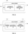
- FIG. 2 is a block diagram of the components of the vibration analyzer 100A-C according to an embodiment of the invention.
- the vibration analyzer 100A-C includes the housing 102, the interface port 104 in the form of a USB connector, a host interface microcontroller 106 and a 1/2/3 axis accelerometer/vibration sensor 108.
- the housing 102 can be the shaped into any shape desired by the user.
- the host interface microcontroller 106 can control the operations of the vibration analyzer 100A-C and includes software to operate the vibration analyzer and to communicate with another device, such as a scan tool or a computing device.
- the host interface microcontroller 106 includes a memory (not shown) to store the software and any data received by the vibration analyzer 100A-C. Further, depending on the type of sensor 108 used, the host interface microcontroller 106 may include an analog to digital converter.
- the host interface microcontroller 106 can also calculate and format the data received from the sensor and/or the vehicle data from the electronic control unit in the vehicle. The formatted data can then be sent to another device in the format useable for that device.
- the 1/2/3 axis accelerometer/vibration sensor 108 allows detection of the vibration in all three axis (x-y-z).
- the sensor 108 may include a MEMS accelerometer. By detecting in all three axis, the vibration analyzer 100A-C can detect the vibration in any direction and is not necessarily dependent on the correct directional detection placement in order to function properly. That is the vibration analyzer 100A-C does not have to be placed or mounted on the plane of the measured vibration axis.
- the 1/2/3 axis accelerometer/vibration sensor 108 can communicate with and be controlled by the host interface microcontroller 106.
- the interface port 104 may be a USB port that allows communication with another device. Additionally, the interface port 104 allows for power that is available from another device to power the vibration analyzer 100A-C. The interface port 104 also allows for the vibration analyzer 100A-C to be networked with another device, such as a scan tool, computing device or even another vibration analyzer. Additionally, the interface port 104 allows for another device to program or reprogram the vibration analyzer 100A-C. Some programming may include when to send the measured acceleration data (when above a certain threshold), transmitting frequency (to match receiver frequency), formatting, data analysis, and the like.
- FIG. 3 is a block diagram of the components of the vibration analyzer 100A-C according to another embodiment of the invention.
- the vibration analyzer 100A-C includes the housing 102, the interface port 104 in the form of a USB connector, the host interface microcontroller 106 and a 1/2/3 axis accelerometer/vibration sensor 108, a wireless interface 110 and a battery 112.
- the components of FIG. 3 are similar to the components of FIG. 2 except for the addition of the wireless interface 110 and battery 112.
- the wireless interface 110 allows for wireless communication with another device and allows the vibration analyzer 100A-C to be networked with a computing device or another vibration analyzer.
- the wireless interface 110 may communicate in various protocols, such as RF (radio frequency), satellites, cellular phones (analog or digital), Bluetooth®, Wi-Fi, 802.15, Infrared, Zigby, near field communication, Local Area Networks (LAN), WLAN (Wireless Local Area Network), or other wireless communication configurations and standards.
- the wireless interface 110 may be controlled by the host interface microcontroller 106 and provide information (analyzed data) to and from another device.
- the wireless interface 110 may also receive wirelessly vehicle data from a scan tool or a vehicle communication interface that is coupled to the vehicle OBD (I or II) port.
- the wireless interface 110 may also be part of the components of the vibration analyzer 100A-C shown in FIG. 2 .
- the vibration analyzer 100A-C receives vehicle data from the vehicle's ECU (electronic control unit) through the interface port 104 or through the wireless interface 110.
- the interface port 104 may be any type of connector including a connector for a cable that couples with an OBD (I or II) port in the vehicle.
- the vehicle data such as engine rpm or vehicle speed, is received by the host interface microcontroller 106.
- the vehicle data may also be packaged with the vibration data received from the 1/2/3 axis accelerometer/vibration sensor 108.
- the host interface microcontroller 106 analyzes the vibration data and the vehicle data using conventional analysis software packages and determine the source of the vibration.
- the host interface microcontroller 106 can determine if the vibration meets or surpasses a certain threshold and that it is at a level that requires replacement or repair of the vehicle component. The analyzed data can then be formatted to a format useable by another device and transmitted to another device.
- the battery 112 can be used to power the components of vibration analyzer 100A-C.
- the battery 112 may be Nickel Cadmium, Nickel Metal Hydride, and Lithium Ion, Lithium air, Nickel Hydrogen, and the like.
- the battery may be integrated or replaceable, or rechargeable, as needed.
- the interface port 104 can be used to charge the battery 112 via an external power source.
- the battery 112 can be part of the components described in FIG. 2 .
- the ability to network the vibration analyzer 100A-C with each other and to the scan tool or other computing device allows for the deployment of more than one vibration analyzer 100A-C throughout the vehicle. This allows for faster analysis and quicker location of the vibration. Additionally, the vibration analyzer 100A-C may be programed to forward to another device only data related to vibration that meets certain threshold characteristics. This decreases the amount of false vibration signals produced during testing and allows for quicker diagnosis.
- the self-test of the vibration analyzer 100A-C occurs through the use of the network. Two or more vibration analyzers 100A-C are placed on the same portion of the vehicle, for example an axle or a pipe, and should provide similar signals to a computing device for independent verification. If the signals are similar (within certain frequency, for example) then the vibration analyzers 100A-C are working properly. If the signals are different from each other (by a predetermined range) then one of the vibration analyzers 100A-C is not functioning properly and may need to be calibrated or fixed. This self-test allows the technician to be confident in the data received from the vibration analyzer 100A-C and confident in his diagnosis.
- the embodiments herein include the vibration sensor being integrated in the vibration analyzer. This allows for the sensing and analysis of the vibration data along with the vehicle data in one device.
Landscapes
- Physics & Mathematics (AREA)
- General Physics & Mathematics (AREA)
- Measurement Of Mechanical Vibrations Or Ultrasonic Waves (AREA)
Claims (7)
- System zum Detektieren und Analysieren von Schwingungen, das eine erste Schwingungsanalyseeinrichtung (100A-C), eine vernetzte Rechenvorrichtung und eine zweite Schwingungsanalyseeinrichtung umfasst, wobei die Schwingungsanalyseeinrichtungen jeweils Folgendes umfassen:a) einen Schnittstellenanschluss (104), der konfiguriert ist, verschiedene Verbinder zu koppeln, um die Schwingungsanalyseeinrichtung (100A-C) mit der vernetzten Rechenvorrichtung zu vernetzen;b) einen dreiachsigen Beschleunigungsmesser (108), der konfiguriert ist, eine Schwingung einer Fahrzeugkomponente zu detektieren;c) eine Steuereinheit (106), die konfiguriert ist, eine Funktion der Schwingungsanalyseeinrichtung (100A-C) zu steuern, wobei die Steuereinheit (106) konfiguriert ist, mit dem Schnittstellenanschluss (104) und dem dreiachsigen Beschleunigungsmesser (108) zu kommunizieren; undd) ein Gehäuse (102), in dem der Schnittstellenanschluss (104), der dreiachsige Beschleunigungsmesser (108) und die Steuereinheit (106) untergebracht sind; wobeie) die Steuereinheit (106) Fahrzeugdaten über den Schnittstellenanschluss (104) von einer elektronischen Steuereinheit eines Fahrzeugs und Schwingungsdaten vom dreiachsigen Beschleunigungsmesser (108) aufnimmt und die Steuereinheit (106) die Schwingungsdaten und die Fahrzeugdaten analysiert, um eine Quelle der Schwingung der Fahrzeugkomponente zu bestimmen; wobei
das System dadurch gekennzeichnet ist, dassf) das Gehäuse (102) zu einer Form, die einem Teil der Fahrzeugkomponente ähnlich ist, gestaltbar ist; undg) die erste Schwingungsanalyseeinrichtung (100A-C) konfiguriert ist, eine Prüfung durchzuführen, indem sie ein erstes Schwingungssignal zur vernetzten Rechenvorrichtung sendet, die ein zweites Schwingungssignal von der zweiten Schwingungsanalyseeinrichtung (100A-C), die an derselben Fahrzeugkomponente positioniert ist, empfängt, um zu bestimmen, ob das erste und das zweite Schwingungssignal verschieden sind. - System nach Anspruch 1, das ferner einen Speicher umfasst, in dem Software gespeichert ist, um eine Schwingungsdetektionsfunktion durchzuführen, wobei der Speicher an die Steuereinheit (106) gekoppelt ist.
- System nach Anspruch 1, wobei der Schnittstellenanschluss (104) der Schwingungsanalyseeinrichtung (100A-C) ermöglicht, durch eine externe Leistungsquelle mit Energie versorgt zu werden.
- System nach Anspruch 1, wobei die Form derart gestaltet ist, dass sie durch den Teil der Prüfkomponente gehalten wird.
- Verfahren zum Detektieren und Analysieren von Schwingungen in einer Fahrzeugkomponente, das die folgenden Schritte umfasst:a) Formen eines Gehäuses einer Schwingungsanalyseeinrichtung, das einen Schnittstellenanschluss (104) enthält, der konfiguriert ist, verschiedene Verbinder, einen dreiachsigen Beschleunigungsmesser (108) und eine Steuereinheit (106) derart zu koppeln, dass sie auf eine Oberfläche einer Fahrzeugkomponente passen;b) Erfassen einer Schwingung der Fahrzeugkomponente mit dem dreiachsigen Beschleunigungsmesser (108) der ersten Schwingungsanalyseeinrichtung (100A);c) Verarbeiten von Schwingungsdaten mit der Steuereinheit (106) der ersten Schwingungsanalyseeinrichtung (100A), wobei die Steuereinheit (106) einen Speicher besitzt, der Software enthält;d) Empfangen von Fahrzeugdaten vom Fahrzeug über den Schnittstellenanschluss (104) der ersten Schwingungsanalyseeinrichtung (100A);e) Analysieren mit der Steuereinheit (106) der Schwingungsdaten und der Fahrzeugdaten, um eine Quelle der Schwingung zu bestimmen;f) Durchführen einer Prüfung der ersten Schwingungsanalyseeinrichtung (100A) durch Senden eines Schwingungssignals von der ersten Schwingungsanalyseeinrichtung (100A) zu einer vernetzten entfernten Rechenvorrichtung, die mit der ersten Analyseeinrichtung über den Schnittstellenanschluss (104) verbunden ist und die außerdem ein zweites Schwingungssignal von einer zweiten Schwingungsanalyseeinrichtung (100B), die der ersten Schwingungsanalyseeinrichtung ähnlich ist und an derselben Fahrzeugkomponente positioniert ist, empfängt; undg) Bestimmen auf der Grundlage davon, ob die Schwingungssignale voneinander verschieden sind, ob die erste Schwingungsanalyseeinrichtung (100A) ordnungsgemäß funktioniert.
- System nach Anspruch 1, wobei die Fahrzeugdaten mit den Schwingungsdaten, die von einem dreiachsigen Beschleunigungsmesser (108) empfangen werden, gekapselt sind.
- Verfahren nach Anspruch 5, wobei die Fahrzeugdaten mit den Schwingungsdaten, die von einem dreiachsigen Beschleunigungsmesser (108) empfangen werden, gekapselt sind.
Applications Claiming Priority (2)
| Application Number | Priority Date | Filing Date | Title |
|---|---|---|---|
| US13/840,349 US8935038B2 (en) | 2013-03-15 | 2013-03-15 | Vibration analyzer for vehicle diagnostics |
| PCT/US2014/027962 WO2014143823A1 (en) | 2013-03-15 | 2014-03-14 | Vibration analyzer for vehicle diagnostics |
Publications (3)
| Publication Number | Publication Date |
|---|---|
| EP2972146A1 EP2972146A1 (de) | 2016-01-20 |
| EP2972146A4 EP2972146A4 (de) | 2016-12-21 |
| EP2972146B1 true EP2972146B1 (de) | 2019-11-27 |
Family
ID=51531541
Family Applications (1)
| Application Number | Title | Priority Date | Filing Date |
|---|---|---|---|
| EP14763407.5A Active EP2972146B1 (de) | 2013-03-15 | 2014-03-14 | Vibrationsanalysator für fahrzeugdiagnostik |
Country Status (4)
| Country | Link |
|---|---|
| US (1) | US8935038B2 (de) |
| EP (1) | EP2972146B1 (de) |
| CN (1) | CN105209867B (de) |
| WO (1) | WO2014143823A1 (de) |
Families Citing this family (15)
| Publication number | Priority date | Publication date | Assignee | Title |
|---|---|---|---|---|
| US10775271B2 (en) | 2012-08-22 | 2020-09-15 | Ge Global Sourcing Llc | System for determining conicity of a wheel based on measured vibrations |
| GB2522728A (en) * | 2014-01-31 | 2015-08-05 | Cambridge Consultants | Monitoring device |
| FR3015686B1 (fr) * | 2013-12-23 | 2015-12-04 | Snecma | Banc d'essais, en particulier pour accelerometres |
| JP6265549B2 (ja) * | 2014-10-15 | 2018-01-24 | 三菱重工業株式会社 | ポイント算出装置、ポイント算出方法及びプログラム |
| US10167004B2 (en) | 2015-12-18 | 2019-01-01 | General Electric Company | Sensor system |
| CN105547451A (zh) * | 2016-01-22 | 2016-05-04 | 华东交通大学 | 一种高速列车车轮空间耦合振动测试的新方法 |
| US11113906B2 (en) | 2018-12-10 | 2021-09-07 | Gm Cruise Holdings Llc | Predictive maintenance and diagnostics using modular condition monitoring |
| CN109632078A (zh) * | 2018-12-30 | 2019-04-16 | 北京化工大学 | 一种可变结构柔性振动变送器及其控制方法 |
| EP4070040A4 (de) | 2019-12-03 | 2023-06-14 | Fluid Handling LLC | Betriebszustandsüberwachungssystem |
| GB2595516A (en) * | 2020-05-29 | 2021-12-01 | Appy Risk Tech Limited | Device for vehicle monitoring and system including same |
| GB2595515A (en) * | 2020-05-29 | 2021-12-01 | Appy Risk Tech Limited | Device for vehicle monitoring and system including same |
| CN112069452B (zh) * | 2020-09-04 | 2024-07-30 | 上海钧正网络科技有限公司 | 用于车辆的器件紧固程度检测方法和装置、检测设备及计算机可读介质 |
| CN113740041A (zh) * | 2021-07-29 | 2021-12-03 | 福建省永正工程质量检测有限公司 | 一种基于振动测试的工程健康诊断分析系统 |
| CN113932915B (zh) * | 2021-09-23 | 2024-02-20 | 北京机电工程研究所 | 一种振动测量通道方向错误识别方法 |
| CN116593906B (zh) * | 2023-03-03 | 2026-03-10 | 宇通客车股份有限公司 | 一种车辆及其电池箱性能监测方法、系统 |
Citations (2)
| Publication number | Priority date | Publication date | Assignee | Title |
|---|---|---|---|---|
| DE4134902A1 (de) * | 1990-11-29 | 1992-06-04 | Mitsubishi Electric Corp | Vorrichtung zum erfassen des aufpralls eines fahrzeuges |
| DE10242128A1 (de) * | 2002-09-11 | 2004-03-25 | Robert Bosch Gmbh | Verfahren und Vorrichtung zur Überwachung einer redundanten Sensoranordnung |
Family Cites Families (17)
| Publication number | Priority date | Publication date | Assignee | Title |
|---|---|---|---|---|
| US6382026B1 (en) * | 1998-05-19 | 2002-05-07 | Matsushita Electric Industrial Co., Ltd. | Acceleration sensor and acceleration apparatus using acceleration sensor |
| US6392584B1 (en) * | 2000-01-04 | 2002-05-21 | Richard Eklund | System and method for detecting and warning of potential failure of rotating and vibrating machines |
| US20040102880A1 (en) * | 2001-10-17 | 2004-05-27 | Brown James K | System for monitoring vehicle wheel vibration |
| US20030088346A1 (en) | 2001-10-27 | 2003-05-08 | Vetronix Corporation | Noise, vibration and harshness analyzer |
| US7129827B2 (en) * | 2003-08-01 | 2006-10-31 | Hoon Bai | Resettable motor vehicle maintenance interval monitor by operating time |
| US7719416B2 (en) * | 2005-09-09 | 2010-05-18 | Microstrain, Inc. | Energy harvesting, wireless structural health monitoring system |
| US7412899B2 (en) * | 2005-09-16 | 2008-08-19 | International Electronic Machines Corporation | MEMS-based monitoring |
| US7578193B2 (en) * | 2006-06-28 | 2009-08-25 | Sauer-Danfoss Inc. | Method of measuring vibration on a device |
| CN100453985C (zh) * | 2007-08-28 | 2009-01-21 | 北京航空航天大学 | 便携式双通道振动故障诊断仪 |
| ITTO20070869A1 (it) | 2007-11-30 | 2009-06-01 | Leonardo Chiarion | Dispositivo per il monitoraggio e l'analisi della conduzione di un autoveicolo |
| US8112281B2 (en) | 2007-12-19 | 2012-02-07 | Enbiomedic | Accelerometer-based control of wearable audio recorders |
| US7801700B2 (en) * | 2008-08-05 | 2010-09-21 | Oracle America, Inc. | Simulating a vibration pattern in a computer subsystem |
| CA2760158C (en) | 2009-04-26 | 2016-08-02 | Nike International Ltd. | Gps features and functionality in an athletic watch system |
| JP2011221002A (ja) * | 2010-03-25 | 2011-11-04 | Sanyo Electric Co Ltd | 振動検出装置、空気圧検出端末および加速度検出システム |
| US20110248846A1 (en) * | 2010-04-13 | 2011-10-13 | Green SHM Systems, Inc, Incorporated | Wireless Sensing Module and Method of Operation |
| TW201224859A (en) | 2010-12-03 | 2012-06-16 | Hon Hai Prec Ind Co Ltd | Ring-shaped input device |
| EP2812661B1 (de) * | 2012-02-10 | 2019-11-27 | Appareo Systems, LLC | System zur überwachung einer strukturellen integrität und nutzung mit anpassbarer frequenz |
-
2013
- 2013-03-15 US US13/840,349 patent/US8935038B2/en not_active Expired - Fee Related
-
2014
- 2014-03-14 CN CN201480027468.8A patent/CN105209867B/zh not_active Expired - Fee Related
- 2014-03-14 WO PCT/US2014/027962 patent/WO2014143823A1/en not_active Ceased
- 2014-03-14 EP EP14763407.5A patent/EP2972146B1/de active Active
Patent Citations (2)
| Publication number | Priority date | Publication date | Assignee | Title |
|---|---|---|---|---|
| DE4134902A1 (de) * | 1990-11-29 | 1992-06-04 | Mitsubishi Electric Corp | Vorrichtung zum erfassen des aufpralls eines fahrzeuges |
| DE10242128A1 (de) * | 2002-09-11 | 2004-03-25 | Robert Bosch Gmbh | Verfahren und Vorrichtung zur Überwachung einer redundanten Sensoranordnung |
Also Published As
| Publication number | Publication date |
|---|---|
| CN105209867A (zh) | 2015-12-30 |
| WO2014143823A1 (en) | 2014-09-18 |
| US20140277911A1 (en) | 2014-09-18 |
| CN105209867B (zh) | 2017-12-15 |
| US8935038B2 (en) | 2015-01-13 |
| EP2972146A4 (de) | 2016-12-21 |
| EP2972146A1 (de) | 2016-01-20 |
Similar Documents
| Publication | Publication Date | Title |
|---|---|---|
| EP2972146B1 (de) | Vibrationsanalysator für fahrzeugdiagnostik | |
| US9704307B2 (en) | Vehicle diagnostics apparatus, diagnostics unit and methods | |
| EP3572819B1 (de) | Verfahren zur bestimmung räumlicher konfigurationen von einer vielzahl von wandlern in bezug auf ein zielobjekt | |
| EP3397935B1 (de) | Vibrations- und geräuschabbildungssystem und -verfahren | |
| US20100211253A1 (en) | Intelligent continuous monitoring system for application in shock absorbers | |
| CN103115666A (zh) | 基于混响室测试评价整车的隔声性能的方法 | |
| KR20090065694A (ko) | 구조물의 모니터링을 위한 무선 계측 방법 및 그 장치 | |
| CN103443426A (zh) | 用于诊断内燃机的增压系统的方法 | |
| US12140607B2 (en) | Safe measurement of tire characteristics | |
| CN114964682A (zh) | 乘用车前端冷却模块隔振橡胶隔振量测试方法 | |
| KR20120009122A (ko) | 자동차 부품 성능 실시간 멀티 테스트 시스템 | |
| JP6448140B2 (ja) | 車両特性解析方法及び装置並びに車両試験装置 | |
| CN111985347A (zh) | 一种白车身模态识别方法及装置 | |
| CN114353927B (zh) | 无线式振动探头 | |
| US20220189219A1 (en) | Adapter | |
| CN116698331B (zh) | 基于汽车空调的管路振动试验系统 | |
| KR100418117B1 (ko) | 차량 진동구조물의 이상 진단장치 | |
| CN103048107A (zh) | 超大型结构件的整体振动测试系统及方法 | |
| Niţu et al. | Considerations on the Proper Selection of Sensors for Vibroacoustic Study | |
| CN113075423A (zh) | 一种测试产品内置三轴加速度传感器性能一致性的装置 | |
| KR20080058024A (ko) | 소음 및 진동 측정 장치 | |
| KR20220060666A (ko) | 차량 전압 측정을 위한 차량 진단 정보 수집 장치 및 이를 이용한 차량 전압 측정 방법 | |
| CN112834814A (zh) | 一种对工程测量传感信号进行采样的系统及使用方法 |
Legal Events
| Date | Code | Title | Description |
|---|---|---|---|
| PUAI | Public reference made under article 153(3) epc to a published international application that has entered the european phase |
Free format text: ORIGINAL CODE: 0009012 |
|
| 17P | Request for examination filed |
Effective date: 20151015 |
|
| AK | Designated contracting states |
Kind code of ref document: A1 Designated state(s): AL AT BE BG CH CY CZ DE DK EE ES FI FR GB GR HR HU IE IS IT LI LT LU LV MC MK MT NL NO PL PT RO RS SE SI SK SM TR |
|
| AX | Request for extension of the european patent |
Extension state: BA ME |
|
| DAX | Request for extension of the european patent (deleted) | ||
| A4 | Supplementary search report drawn up and despatched |
Effective date: 20161117 |
|
| RIC1 | Information provided on ipc code assigned before grant |
Ipc: G01H 1/10 20060101AFI20161111BHEP Ipc: G01H 1/00 20060101ALI20161111BHEP Ipc: G01M 7/00 20060101ALI20161111BHEP Ipc: G07C 5/00 20060101ALI20161111BHEP |
|
| STAA | Information on the status of an ep patent application or granted ep patent |
Free format text: STATUS: EXAMINATION IS IN PROGRESS |
|
| 17Q | First examination report despatched |
Effective date: 20171010 |
|
| GRAP | Despatch of communication of intention to grant a patent |
Free format text: ORIGINAL CODE: EPIDOSNIGR1 |
|
| STAA | Information on the status of an ep patent application or granted ep patent |
Free format text: STATUS: GRANT OF PATENT IS INTENDED |
|
| INTG | Intention to grant announced |
Effective date: 20190621 |
|
| GRAS | Grant fee paid |
Free format text: ORIGINAL CODE: EPIDOSNIGR3 |
|
| GRAA | (expected) grant |
Free format text: ORIGINAL CODE: 0009210 |
|
| STAA | Information on the status of an ep patent application or granted ep patent |
Free format text: STATUS: THE PATENT HAS BEEN GRANTED |
|
| AK | Designated contracting states |
Kind code of ref document: B1 Designated state(s): AL AT BE BG CH CY CZ DE DK EE ES FI FR GB GR HR HU IE IS IT LI LT LU LV MC MK MT NL NO PL PT RO RS SE SI SK SM TR |
|
| REG | Reference to a national code |
Ref country code: GB Ref legal event code: FG4D |
|
| REG | Reference to a national code |
Ref country code: CH Ref legal event code: EP |
|
| REG | Reference to a national code |
Ref country code: DE Ref legal event code: R096 Ref document number: 602014057505 Country of ref document: DE |
|
| REG | Reference to a national code |
Ref country code: AT Ref legal event code: REF Ref document number: 1207213 Country of ref document: AT Kind code of ref document: T Effective date: 20191215 |
|
| REG | Reference to a national code |
Ref country code: IE Ref legal event code: FG4D |
|
| REG | Reference to a national code |
Ref country code: NL Ref legal event code: MP Effective date: 20191127 |
|
| REG | Reference to a national code |
Ref country code: LT Ref legal event code: MG4D |
|
| RAP2 | Party data changed (patent owner data changed or rights of a patent transferred) |
Owner name: ROBERT BOSCH GMBH Owner name: BOSCH AUTOMOTIVE SERVICE SOLUTIONS INC. |
|
| PG25 | Lapsed in a contracting state [announced via postgrant information from national office to epo] |
Ref country code: NL Free format text: LAPSE BECAUSE OF FAILURE TO SUBMIT A TRANSLATION OF THE DESCRIPTION OR TO PAY THE FEE WITHIN THE PRESCRIBED TIME-LIMIT Effective date: 20191127 Ref country code: LT Free format text: LAPSE BECAUSE OF FAILURE TO SUBMIT A TRANSLATION OF THE DESCRIPTION OR TO PAY THE FEE WITHIN THE PRESCRIBED TIME-LIMIT Effective date: 20191127 Ref country code: NO Free format text: LAPSE BECAUSE OF FAILURE TO SUBMIT A TRANSLATION OF THE DESCRIPTION OR TO PAY THE FEE WITHIN THE PRESCRIBED TIME-LIMIT Effective date: 20200227 Ref country code: GR Free format text: LAPSE BECAUSE OF FAILURE TO SUBMIT A TRANSLATION OF THE DESCRIPTION OR TO PAY THE FEE WITHIN THE PRESCRIBED TIME-LIMIT Effective date: 20200228 Ref country code: SE Free format text: LAPSE BECAUSE OF FAILURE TO SUBMIT A TRANSLATION OF THE DESCRIPTION OR TO PAY THE FEE WITHIN THE PRESCRIBED TIME-LIMIT Effective date: 20191127 Ref country code: LV Free format text: LAPSE BECAUSE OF FAILURE TO SUBMIT A TRANSLATION OF THE DESCRIPTION OR TO PAY THE FEE WITHIN THE PRESCRIBED TIME-LIMIT Effective date: 20191127 Ref country code: FI Free format text: LAPSE BECAUSE OF FAILURE TO SUBMIT A TRANSLATION OF THE DESCRIPTION OR TO PAY THE FEE WITHIN THE PRESCRIBED TIME-LIMIT Effective date: 20191127 Ref country code: BG Free format text: LAPSE BECAUSE OF FAILURE TO SUBMIT A TRANSLATION OF THE DESCRIPTION OR TO PAY THE FEE WITHIN THE PRESCRIBED TIME-LIMIT Effective date: 20200227 |
|
| PG25 | Lapsed in a contracting state [announced via postgrant information from national office to epo] |
Ref country code: RS Free format text: LAPSE BECAUSE OF FAILURE TO SUBMIT A TRANSLATION OF THE DESCRIPTION OR TO PAY THE FEE WITHIN THE PRESCRIBED TIME-LIMIT Effective date: 20191127 Ref country code: IS Free format text: LAPSE BECAUSE OF FAILURE TO SUBMIT A TRANSLATION OF THE DESCRIPTION OR TO PAY THE FEE WITHIN THE PRESCRIBED TIME-LIMIT Effective date: 20200327 Ref country code: HR Free format text: LAPSE BECAUSE OF FAILURE TO SUBMIT A TRANSLATION OF THE DESCRIPTION OR TO PAY THE FEE WITHIN THE PRESCRIBED TIME-LIMIT Effective date: 20191127 |
|
| PG25 | Lapsed in a contracting state [announced via postgrant information from national office to epo] |
Ref country code: AL Free format text: LAPSE BECAUSE OF FAILURE TO SUBMIT A TRANSLATION OF THE DESCRIPTION OR TO PAY THE FEE WITHIN THE PRESCRIBED TIME-LIMIT Effective date: 20191127 |
|
| PG25 | Lapsed in a contracting state [announced via postgrant information from national office to epo] |
Ref country code: EE Free format text: LAPSE BECAUSE OF FAILURE TO SUBMIT A TRANSLATION OF THE DESCRIPTION OR TO PAY THE FEE WITHIN THE PRESCRIBED TIME-LIMIT Effective date: 20191127 Ref country code: PT Free format text: LAPSE BECAUSE OF FAILURE TO SUBMIT A TRANSLATION OF THE DESCRIPTION OR TO PAY THE FEE WITHIN THE PRESCRIBED TIME-LIMIT Effective date: 20200419 Ref country code: DK Free format text: LAPSE BECAUSE OF FAILURE TO SUBMIT A TRANSLATION OF THE DESCRIPTION OR TO PAY THE FEE WITHIN THE PRESCRIBED TIME-LIMIT Effective date: 20191127 Ref country code: ES Free format text: LAPSE BECAUSE OF FAILURE TO SUBMIT A TRANSLATION OF THE DESCRIPTION OR TO PAY THE FEE WITHIN THE PRESCRIBED TIME-LIMIT Effective date: 20191127 Ref country code: CZ Free format text: LAPSE BECAUSE OF FAILURE TO SUBMIT A TRANSLATION OF THE DESCRIPTION OR TO PAY THE FEE WITHIN THE PRESCRIBED TIME-LIMIT Effective date: 20191127 Ref country code: RO Free format text: LAPSE BECAUSE OF FAILURE TO SUBMIT A TRANSLATION OF THE DESCRIPTION OR TO PAY THE FEE WITHIN THE PRESCRIBED TIME-LIMIT Effective date: 20191127 |
|
| REG | Reference to a national code |
Ref country code: DE Ref legal event code: R097 Ref document number: 602014057505 Country of ref document: DE |
|
| PG25 | Lapsed in a contracting state [announced via postgrant information from national office to epo] |
Ref country code: SM Free format text: LAPSE BECAUSE OF FAILURE TO SUBMIT A TRANSLATION OF THE DESCRIPTION OR TO PAY THE FEE WITHIN THE PRESCRIBED TIME-LIMIT Effective date: 20191127 Ref country code: SK Free format text: LAPSE BECAUSE OF FAILURE TO SUBMIT A TRANSLATION OF THE DESCRIPTION OR TO PAY THE FEE WITHIN THE PRESCRIBED TIME-LIMIT Effective date: 20191127 |
|
| REG | Reference to a national code |
Ref country code: AT Ref legal event code: MK05 Ref document number: 1207213 Country of ref document: AT Kind code of ref document: T Effective date: 20191127 |
|
| REG | Reference to a national code |
Ref country code: DE Ref legal event code: R119 Ref document number: 602014057505 Country of ref document: DE |
|
| PLBE | No opposition filed within time limit |
Free format text: ORIGINAL CODE: 0009261 |
|
| STAA | Information on the status of an ep patent application or granted ep patent |
Free format text: STATUS: NO OPPOSITION FILED WITHIN TIME LIMIT |
|
| PG25 | Lapsed in a contracting state [announced via postgrant information from national office to epo] |
Ref country code: MC Free format text: LAPSE BECAUSE OF FAILURE TO SUBMIT A TRANSLATION OF THE DESCRIPTION OR TO PAY THE FEE WITHIN THE PRESCRIBED TIME-LIMIT Effective date: 20191127 |
|
| REG | Reference to a national code |
Ref country code: CH Ref legal event code: PL |
|
| 26N | No opposition filed |
Effective date: 20200828 |
|
| PG25 | Lapsed in a contracting state [announced via postgrant information from national office to epo] |
Ref country code: SI Free format text: LAPSE BECAUSE OF FAILURE TO SUBMIT A TRANSLATION OF THE DESCRIPTION OR TO PAY THE FEE WITHIN THE PRESCRIBED TIME-LIMIT Effective date: 20191127 Ref country code: PL Free format text: LAPSE BECAUSE OF FAILURE TO SUBMIT A TRANSLATION OF THE DESCRIPTION OR TO PAY THE FEE WITHIN THE PRESCRIBED TIME-LIMIT Effective date: 20191127 Ref country code: AT Free format text: LAPSE BECAUSE OF FAILURE TO SUBMIT A TRANSLATION OF THE DESCRIPTION OR TO PAY THE FEE WITHIN THE PRESCRIBED TIME-LIMIT Effective date: 20191127 |
|
| REG | Reference to a national code |
Ref country code: BE Ref legal event code: MM Effective date: 20200331 |
|
| PG25 | Lapsed in a contracting state [announced via postgrant information from national office to epo] |
Ref country code: LU Free format text: LAPSE BECAUSE OF NON-PAYMENT OF DUE FEES Effective date: 20200314 |
|
| PG25 | Lapsed in a contracting state [announced via postgrant information from national office to epo] |
Ref country code: CH Free format text: LAPSE BECAUSE OF NON-PAYMENT OF DUE FEES Effective date: 20200331 Ref country code: IE Free format text: LAPSE BECAUSE OF NON-PAYMENT OF DUE FEES Effective date: 20200314 Ref country code: LI Free format text: LAPSE BECAUSE OF NON-PAYMENT OF DUE FEES Effective date: 20200331 Ref country code: FR Free format text: LAPSE BECAUSE OF NON-PAYMENT OF DUE FEES Effective date: 20200331 Ref country code: IT Free format text: LAPSE BECAUSE OF FAILURE TO SUBMIT A TRANSLATION OF THE DESCRIPTION OR TO PAY THE FEE WITHIN THE PRESCRIBED TIME-LIMIT Effective date: 20191127 Ref country code: DE Free format text: LAPSE BECAUSE OF NON-PAYMENT OF DUE FEES Effective date: 20201001 |
|
| PG25 | Lapsed in a contracting state [announced via postgrant information from national office to epo] |
Ref country code: BE Free format text: LAPSE BECAUSE OF NON-PAYMENT OF DUE FEES Effective date: 20200331 |
|
| GBPC | Gb: european patent ceased through non-payment of renewal fee |
Effective date: 20200314 |
|
| PG25 | Lapsed in a contracting state [announced via postgrant information from national office to epo] |
Ref country code: GB Free format text: LAPSE BECAUSE OF NON-PAYMENT OF DUE FEES Effective date: 20200314 |
|
| PG25 | Lapsed in a contracting state [announced via postgrant information from national office to epo] |
Ref country code: TR Free format text: LAPSE BECAUSE OF FAILURE TO SUBMIT A TRANSLATION OF THE DESCRIPTION OR TO PAY THE FEE WITHIN THE PRESCRIBED TIME-LIMIT Effective date: 20191127 Ref country code: MT Free format text: LAPSE BECAUSE OF FAILURE TO SUBMIT A TRANSLATION OF THE DESCRIPTION OR TO PAY THE FEE WITHIN THE PRESCRIBED TIME-LIMIT Effective date: 20191127 Ref country code: CY Free format text: LAPSE BECAUSE OF FAILURE TO SUBMIT A TRANSLATION OF THE DESCRIPTION OR TO PAY THE FEE WITHIN THE PRESCRIBED TIME-LIMIT Effective date: 20191127 |
|
| PG25 | Lapsed in a contracting state [announced via postgrant information from national office to epo] |
Ref country code: MK Free format text: LAPSE BECAUSE OF FAILURE TO SUBMIT A TRANSLATION OF THE DESCRIPTION OR TO PAY THE FEE WITHIN THE PRESCRIBED TIME-LIMIT Effective date: 20191127 |