EP2972196B1 - Verfahren zur auftriebsmessung in beton - Google Patents
Verfahren zur auftriebsmessung in beton Download PDFInfo
- Publication number
- EP2972196B1 EP2972196B1 EP14764306.8A EP14764306A EP2972196B1 EP 2972196 B1 EP2972196 B1 EP 2972196B1 EP 14764306 A EP14764306 A EP 14764306A EP 2972196 B1 EP2972196 B1 EP 2972196B1
- Authority
- EP
- European Patent Office
- Prior art keywords
- force
- buoy
- buoyancy
- drum
- measured
- Prior art date
- Legal status (The legal status is an assumption and is not a legal conclusion. Google has not performed a legal analysis and makes no representation as to the accuracy of the status listed.)
- Not-in-force
Links
Images


Classifications
-
- G—PHYSICS
- G01—MEASURING; TESTING
- G01N—INVESTIGATING OR ANALYSING MATERIALS BY DETERMINING THEIR CHEMICAL OR PHYSICAL PROPERTIES
- G01N33/00—Investigating or analysing materials by specific methods not covered by groups G01N1/00 - G01N31/00
- G01N33/38—Concrete; Lime; Mortar; Gypsum; Bricks; Ceramics; Glass
- G01N33/383—Concrete or cement
-
- B—PERFORMING OPERATIONS; TRANSPORTING
- B28—WORKING CEMENT, CLAY, OR STONE
- B28C—PREPARING CLAY; PRODUCING MIXTURES CONTAINING CLAY OR CEMENTITIOUS MATERIAL, e.g. PLASTER
- B28C5/00—Apparatus or methods for producing mixtures of cement with other substances, e.g. slurries, mortars, porous or fibrous compositions
- B28C5/42—Apparatus specially adapted for being mounted on vehicles with provision for mixing during transport
- B28C5/4203—Details; Accessories
- B28C5/4206—Control apparatus; Drive systems, e.g. coupled to the vehicle drive-system
- B28C5/422—Controlling or measuring devices
-
- B—PERFORMING OPERATIONS; TRANSPORTING
- B28—WORKING CEMENT, CLAY, OR STONE
- B28C—PREPARING CLAY; PRODUCING MIXTURES CONTAINING CLAY OR CEMENTITIOUS MATERIAL, e.g. PLASTER
- B28C7/00—Controlling the operation of apparatus for producing mixtures of clay or cement with other substances; Supplying or proportioning the ingredients for mixing clay or cement with other substances; Discharging the mixture
- B28C7/02—Controlling the operation of the mixing
-
- G—PHYSICS
- G01—MEASURING; TESTING
- G01N—INVESTIGATING OR ANALYSING MATERIALS BY DETERMINING THEIR CHEMICAL OR PHYSICAL PROPERTIES
- G01N9/00—Investigating density or specific gravity of materials; Analysing materials by determining density or specific gravity
- G01N9/08—Investigating density or specific gravity of materials; Analysing materials by determining density or specific gravity by measuring buoyant force of solid materials by weighing both in air and in a liquid
-
- G—PHYSICS
- G01—MEASURING; TESTING
- G01N—INVESTIGATING OR ANALYSING MATERIALS BY DETERMINING THEIR CHEMICAL OR PHYSICAL PROPERTIES
- G01N9/00—Investigating density or specific gravity of materials; Analysing materials by determining density or specific gravity
- G01N9/10—Investigating density or specific gravity of materials; Analysing materials by determining density or specific gravity by observing bodies wholly or partially immersed in fluid materials
- G01N9/12—Investigating density or specific gravity of materials; Analysing materials by determining density or specific gravity by observing bodies wholly or partially immersed in fluid materials by observing the depth of immersion of the bodies, e.g. hydrometers
- G01N9/14—Investigating density or specific gravity of materials; Analysing materials by determining density or specific gravity by observing bodies wholly or partially immersed in fluid materials by observing the depth of immersion of the bodies, e.g. hydrometers the body being built into a container
-
- G—PHYSICS
- G01—MEASURING; TESTING
- G01N—INVESTIGATING OR ANALYSING MATERIALS BY DETERMINING THEIR CHEMICAL OR PHYSICAL PROPERTIES
- G01N9/00—Investigating density or specific gravity of materials; Analysing materials by determining density or specific gravity
- G01N9/26—Investigating density or specific gravity of materials; Analysing materials by determining density or specific gravity by measuring pressure differences
-
- G—PHYSICS
- G01—MEASURING; TESTING
- G01N—INVESTIGATING OR ANALYSING MATERIALS BY DETERMINING THEIR CHEMICAL OR PHYSICAL PROPERTIES
- G01N9/00—Investigating density or specific gravity of materials; Analysing materials by determining density or specific gravity
- G01N9/36—Analysing materials by measuring the density or specific gravity, e.g. determining quantity of moisture
-
- G—PHYSICS
- G01—MEASURING; TESTING
- G01N—INVESTIGATING OR ANALYSING MATERIALS BY DETERMINING THEIR CHEMICAL OR PHYSICAL PROPERTIES
- G01N9/00—Investigating density or specific gravity of materials; Analysing materials by determining density or specific gravity
- G01N9/26—Investigating density or specific gravity of materials; Analysing materials by determining density or specific gravity by measuring pressure differences
- G01N2009/263—Investigating density or specific gravity of materials; Analysing materials by determining density or specific gravity by measuring pressure differences using vertically-movable pressure transducer
Definitions
- the improvements generally relate to the field of concrete production, and more particularly refers to measuring buoyancy in concrete to allow evaluation of fresh concrete density and air content in ready mix drum.
- Density is usually calculated by dividing a known volume of material by its weight. For a given composition, the measured (including indirect method such as pressiometer) or calculated density of fresh concrete can be compared to the theoretical density without considering the presence of air to calculate the theoretical air content.
- the measure of density usually requires the use of a container of known volume that is filled with the fresh concrete and the weight of the concrete is determined by discounting the weight of the container.
- a method of calculating buoyancy is provided which can be done without the need for sampling and moreover, automatically (without human intervention).
- the method can use a probe element immersed in fresh concrete in a ready mix drum.
- the calculated buoyancy can be used in determining the density of concrete, which, in turn, can be used in determining the air content.
- a method of generating a signal indicative of buoyancy of a buoy immersed in fresh concrete contained in a ready mix drum rotatable about a central axis, the central axis being at least partially horizontally-oriented, said buoy being mounted on an inner surface of said drum and moved along a circular path when the drum is rotated said method comprising : rotating the drum about the central axis, to move the buoy inside said fresh concrete across a vertical minimum position along the circular path, and measuring a first force exerted on said buoy as said buoy is moved across the vertical minimum position, said first force being representative of yield stress; rotating the drum about the central axis, to move the buoy inside said fresh concrete across a maximum lateral position along the circular path, and measuring a second force exerted on said buoy as said buoy is moved across the maximum lateral position, said second force being representative of combined yield stress and buoyancy; subtracting the measured first force across the vertical minimum position from the measured second force across the maximum lateral position; and generating a signal indicative of said
- buoy is used in a general manner to refer to a buoy which exhibits a significant positive or negative buoyancy in fresh concrete.
- a buoy with positive buoyancy will raise (float) more or less rapidly, whereas a buoy with negative buoyancy will descend (sink) more or less rapidly.
- the ascending or descending speed depends on the fluid viscosity, as described by Stoke's 2 nd law.
- Fresh concrete is a complex material which exhibits a viscous characteristics but that also has, most of the time, a yield stress that must be overcome before any immersed buoy can start to move trough it (this explains why the aggregate material does not sink too much in fresh concrete).
- the shape of the immersed buoy more precisely its projected surface in the direction of the movement, factored by the fluid yield stress, opposes the buoyancy force (in both directions when the buoy is not moving).
- measurements can be made at two particular positions within the circular travel path of a probe as the drum of the ready mix is rotated about its axis to isolate the buoyancy from the yield stress and factor the yield stress out of the equation.
- the position of the probe along the circular travel path can be determined using a position sensor which can optionally be combined into a probe having a load sensor.
- a position sensor which can optionally be combined into a probe having a load sensor.
- determination of position using a probe having accelerometers working in different axes is described in international patent publication no. WO 2011/042880 .
- Fig. 1 shows an example of a probe 10 which can incorporate a position sensor such as described in the above identified reference, for instance.
- the example probe 10 shown in Fig. 1 is designed to harness the buoyancy of a buoy 12 immersed in fresh concrete. More specifically, the probe 10 includes a housing 14 having a base 16 fixable to an interior surface of the cylindrical wall of the ready mix drum, the housing 14 having an aperture 18 opposite the base 16 and enclosing an inner cavity 20 between the aperture 18 and the base 16.
- a pivoting member 22 is used, having a first end 24 engaged in the inner cavity 20 through the aperture 18 and a second end 26 protruding outwardly from the housing 14, away from the base 16, the pivoting member 22 being pivotally mounted to the housing 14 about a pivot axis 28 which is oriented parallel to the central axis of the ready mix drum when the probe 10 is mounted to the interior surface of the cylindrical wall of the ready mix drum (see Fig. 2 ).
- the pivoting member 22 is provided with the buoy 12 made integral to the second end 26, and a counterweight 30 provided by the first end 24.
- At least one deformable member 32 are mounted between the pivoting member 22 and the housing 14 in a manner that load cells 34 mounted thereto can measure a rotary force exerted on the pivoting member 22 around the pivot axis 28.
- a load cell with protection for overload can be used in alternate embodiments.
- the optional mechanical counterweight 30 is used in this embodiment to at least partially balance the weight of the buoy 12 about the axis 28 when the pivoting member 22 is oriented horizontally, thereby limiting the amount of pivoting force around the axis 28 which would imparted by the weight of the immersed buoy and the lever arm of the center of gravity with the pivot axis 28.
- a deformable soft seal 36 is used to bridge a gap associated with the aperture 18 which would otherwise be present between the pivoting member 22 and the housing 14, and thereby prevents concrete from entering the chamber 20, or inner cavity, where the load sensors 34 formed by the deformable members 32 and strain gages 38 glued thereon can measure the load.
- Protective and replaceable parts 40 such as protective jackets, can be used to shield components of the sensor, such as the housing 14, pivoting member 22, and immersion member 12, from abrasion from the concrete.
- the seal 36 can be placed perpendicular to the normal flow of concrete (i.e. tangential to the rotation axis of the drum) to address wear.
- the load sensor 34 is protected from overload by a rigid body (which, in this case, is provided in the form of a first end 24 of the pivoting member 22 engaged inside the cavity 20, and also serving as the counterweight 30).
- the rigid body restricts the movement of the immersed buoy. When the immersed buoy 12 is moved in the concrete, it tends to move around the pivoting axis 28 given the drag and yield stress exerted thereon by the concrete. This movement is restricted, to a certain extent, by the deformable members 32.
- the end part of the rigid body which is free to move by some small angle, eventually comes into contact with an abutment that stops its movement, constraining it within a given angle span, and protecting the deformable members 32 from plastic deformation.
- a sphere was selected in this embodiment.
- a sphere was found to provide a satisfactory volume / projected surface area ratio. It this case, the volume is increased to increase the buoyancy effect of the immersed buoy and the projected surface (the two dimensional projection of the body along the circular path) is kept satisfactorily low to reduce the effect of the concrete yield stress.
- a cube can provide an even better volume / projected surface area ratio, a sphere is still preferred because it results in less drag when moved in the concrete during normal operation of the ready mix drum and also does not have corners or edges. By comparison, the corners and edges of a cube would likely tend to wear rapidly, which would likely affect the projected surface area and/or the weight of the buoy and therefore affect the precision of the calculation of buoyancy according to the example method detailed below.
- the portion of the pivoting member 22 which extends between the deformable seal 36 and the buoy 12 is provided in a cylindrical shape in this embodiment, which similarly avoids undesired sharp edges.
- a buoy in the shape of a satisfactory hybrid between a sphere and a cube, and a protruding portion of the pivoting member in the shape of a satisfactory hybrid between a rectangular prism and a cylinder can be used, for instance.
- the buoy can be provided in the form of a hollow cylindrical second end of the pivoting member having a rounded tip, for instance.
- the probe 10 can be mounted inside the drum of a ready mix truck 42.
- the load detected by the load sensors can be sent to a processing unit 44 by wireless communication device to a receiver 46 that can be connected to a long range communication device 48 such as used by cellular phone technology, for instance.
- the drum is moved to position the probe at two determined positions referred to herein as the vertical minimum position 50 and lateral, or horizontal, maximum position 52.
- the drum is moved at constant low speed and for small angles back and forth across the vertical minimum position, during which time the pivoting force exerted on the pivoting member is measured (using the load cells in this example).
- the effects of buoyancy on the pivoting force are negligible since the buoyancy force is exerted radially relative to the pivot axis and therefore does not contribute to pivot the pivoting member about the pivot axis.
- the buoyancy force is not detected by the load cells in this example when the probe is at the vertical minimum position.
- the measured load is thus indicative of yield stress on the immersed buoy (without having to use two different speeds).
- the speed at which the measures are taken should be low, such as lower than 0.1 rotation per minute for instance, for a typical ready mix drum of a concrete truck.
- lower speed will typically also lead to a longer time period to conduct the measures and the calculations.
- speed can be between 0.01 and 0.05 RPM and the small angle movement can be performed for angles within 5 degrees of the original vertical position (e.g. between 1-2 degrees) in order not to bias the yield stress measurement with buoyancy effects.
- the same measurement of the pivoting force on the pivoting member is done while the probe is moved around the horizontal position 16.
- the movements can be the same as those described above in terms of speed and angle limits.
- buoyancy affects the pivoting force, in addition to the effects of yield stress.
- the portion of the pivoting force relating to buoyancy can be obtained simply by subtracting yield stress imparted load from the total measured load.
- a servo control hydraulic valve can be used to automatically place the sensor at the desired position and proceed with the small movements indicated in the procedure described above.
- the buoyancy force is determined and the density of the concrete (or other fluid) can be calculated in a manner exemplified below where measured loads were converted into pressures, considering the lever arm of each force, for convenience and ease of calculation :
- P1 Equivalent pressure on immersed buoy measured in clockwise direction in minimal vertical (bottom) position.
- P2 Equivalent pressure on immersed buoy measured in anti-clockwise direction in minimal vertical (bottom) position.
- P3 Equivalent pressure on immersed buoy measured in clockwise direction in horizontal (mid-level) position.
- P4 Equivalent pressure on immersed buoy measured in anti-clockwise direction in horizontal (mid-level) position.
- the buoyancy pressure (over the total projected surface of the immersed buoy) equal 0.9 kPa or 900 N/m 2 .
- the buoyancy forces "B force " of the fluid can be calculated by :
- the probe can be provided with a model of their wear rate (change in shape, volume, weight, etc. over a given period of use), in which case the effect of their wear can be considered in the calculation.
- a protective jacket 40 can be used to protect the seal 36, as shown in Figure 1 .
- the density "D” of the fluid is equal to "equivalent mass” divided by the volume divided by the density of water (approx 1kg/liter).
- the buoyancy can be obtained from equation (3) above, and only the two associated measurements can be taken. This can be interesting because the two measurements P3 and P4 associated to equation (3) are made at the same position (the horizontal maximum position in this case) which can allow obtaining the buoyancy indication more rapidly than by using equation (4), for instance.
- any undesired weight effect e.g. weight of the pivoting member and associated components exerting a significant moment of force in any direction around the pivot when in the horizontal maximum position, see below
- equation (3) or (4) can bias the use of equation (1) or (2).
- the buoy 12 together with the entire portion of the pivoting member 22 extending past the pivot 28 when in the horizontal orientation, has a weight which has the effect of a downwardly oriented force acting on a center of gravity offset from the pivot 28 by a lever arm distance, and therefore imparts a moment around the pivot 28.
- the counterweight 30 together with the entire portion of the pivoting member 22 extending on the opposite side of the pivot 28 relative the buoy 12, also has the effect of a downwardly oriented force acting on a corresponding other center of gravity, also offset from the pivot 28 but on the other side.
- the counterweight 30 exerts a moment around the pivot 28 which counteracts the moment associated to the buoy 12.
- W effect can be said to be the effect of the net balance between these two counteracting moments, where a negative value was selected to indicate a weight-imparted moment of force opposite the one associated to the buoyancy in this example.
- W effect can be considered negligible, i.e. ⁇ 0.
- a satisfactory indication of buoyancy can also be obtained by either one equations (1) or (2) above, rather than having to factor out this effect using equations (3) or (4), for instance.
- the example detailed above uses the horizontal position and also uses the vertical minimum position to within a satisfactory degree of precision (e.g. within 5 degrees).
- the advantage of using these positions has been outlined above and can be summarized by saying that in the vertical minimum position, the tangential component of buoyancy (the only component which can be measured using the probe 10 shown in Fig. 1 ), is nil, which allows to single out the effect of Yield stress; whereas in the horizontal maximum position, the effect of buoyancy is entirely tangential, which directly allows to measure its full effect.
- an indication of the buoyancy can be obtained by taking measures at a single position by using a sensor which measure tangential forces such as described above, but which can additionally measure radial buoyancy forces.
- tangential force measures can be taken when the probe is moved in the tangential direction during one step, and an other step can include measuring the radial buoyancy force at the same position while the drum is not rotated.
- the position can conveniently be selected to be the vertical minimum position, for instance, in which the buoyancy force is exerted fully in the radial direction, which allows to readily determine the Yield from the tangential force measurement and then subtract it from the radial force measurement.
- the radial force measurement can be obtained using a buoy exhibiting positive or negative buoyancy.
- the radial force measurement can include freeing the buoy to allow radial movement over a short distance (e.g. 1 mm), and measuring the residual force at the end of this short distance (e.g. using a traction load cell), for instance.
- a mechanism e.g. electromagnetic, can be provided to selectively hold or release buoy to this end. Assuming a positive buoyancy, for instance, a buoy entraining buoyancy forces that are greater than the yield forces is required, which can require selecting an appropriate volume / projected surface ratio for the immersed body in accordance with the explanations provided above, for instance.
- buoy is used liberally in the context of this specification as it will be understood that a probe such as is described in international patent publication no. WO 2011/042880 , though difficultly associable to a buoy in the everyday use of the term, can present sufficient buoyancy to act as a buoy in the sense intended in this specification.
- the density of the fluid can be determined from force pressures using a pressure/force measurement probe (a potential example of which is described in international patent publication no. WO 2011/042880 ). This can be advantageous in some embodiments.
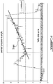
- a way to achieve this involves recording the exerted pressure on the sensor and the associated sensor angle at a plurality of positions along the path of the sensor in the fluid.
- the relationship between pressure and angle depends on the sensor shape and volume as well as of the density of the fluid in which the sensor is traveling. That relationship is expected to be non-linear.
- An example of such a record is plotted in the graph presented in Fig. 4 which shows a sudden increase in pressure and a sudden decrease in pressure associated with the entry and exit of the probe into and out from the concrete, respectively.
- a first step is to extract a set of data which will be referred to herein as the valid data set, associated with a valid data zone of the graph, from the overall data.
- the valid data zone can be determined to be associated with the portion of the graph where the pressure sensor is in the concrete, and more specifically to begin at a minimum pressure point in the concrete and be terminated before the position of exit of the pressure sensor from the concrete.
- the valid data zone is more specifically determined to finish a little before the point of exit to a sufficient extent to avoid pressure perturbations which can be expected to occur around the point of exit of the pressure sensor.
- the extent of the valid data zone depends on the level of concrete in the drum.
- a second step is to plot or otherwise calculate a linear relationship curve which is best fitted with the valid data set.
- This best-fit linear relationship curve is proportional to the concrete density in accordance with a coefficient which is a factor of the fluid and the geometrical and mechanical features of the pressure sensor. Henceforth, the proportionality coefficient can be calibrated against measurements of slope for fluids of known density.
- This technique can be extended to fluids other than concrete being mixed in rotary containers equipped with suitable normal-force pressure sensors (i.e. pressure sensors adapted to determine the normal force imparted against the pressure sensor by the fluid as the pressure sensor is moved in the fluid).
Landscapes
- Chemical & Material Sciences (AREA)
- Life Sciences & Earth Sciences (AREA)
- Health & Medical Sciences (AREA)
- Analytical Chemistry (AREA)
- General Health & Medical Sciences (AREA)
- Pathology (AREA)
- Immunology (AREA)
- Physics & Mathematics (AREA)
- General Physics & Mathematics (AREA)
- Biochemistry (AREA)
- Engineering & Computer Science (AREA)
- Ceramic Engineering (AREA)
- Medicinal Chemistry (AREA)
- Food Science & Technology (AREA)
- Dispersion Chemistry (AREA)
- Mechanical Engineering (AREA)
- Structural Engineering (AREA)
- Testing Or Calibration Of Command Recording Devices (AREA)
- Level Indicators Using A Float (AREA)
Claims (6)
- Verfahren zum Erzeugen eines Signals, das einen Auftrieb einer Boje (12) anzeigt, die in frischen Beton eingetaucht ist, der in einer Fertigmischungstrommel enthalten ist, die um eine Mittelachse herum drehbar ist, wobei die Mittelachse wenigstens teilweise horizontal ausgerichtet ist, wobei die Boje an einer Innenoberfläche der Trommel angebracht ist und entlang einer Kreisbahn bewegt wird, wenn die Trommel gedreht wird, wobei das Verfahren Folgendes umfasst:Drehen der Trommel um die Mittelachse herum, um die Boje in dem Inneren des frischen Betons über eine vertikale Mindestposition (50) entlang der Kreisbahn zu bewegen, und Messen einer ersten Kraft, die auf die Boje ausgeübt wird, während die Boje über die vertikale Mindestposition bewegt wird, wobei die erste Kraft die Fließspannung darstellt;Drehen der Trommel um die Mittelachse, um die Boje in dem Inneren des frischen Betons über eine maximale Seitenposition (52) entlang der Kreisbahn zu bewegen, und Messen einer zweiten Kraft, die auf die Boje ausgeübt wird, wenn die Boje über die maximale Seitenposition bewegt wird, wobei die zweite Kraft die kombinierte Fließspannung und den Auftrieb darstellt;Subtrahieren der gemessenen ersten Kraft über die vertikale Minimalposition von der gemessenen zweiten Kraft über die maximale Seitenposition; undErzeugen eines Signals, das den Auftrieb anzeigt, wenigstens basierend auf der Subtraktion.
- Verfahren nach Anspruch 1, wobei sowohl das Bewegen über eine vertikale Minimalposition als auch das Bewegen über eine laterale Maximalposition ein Bewirken einer Hin- und Herbewegung an der entsprechenden Position beinhalten, und wobei sowohl das Messen der ersten Kraft als auch das Messen der zweiten Kraft ein Mitteln mehrerer Messwerte, die bei einer gegebenen Geschwindigkeit in der entsprechenden gleichen Richtung erfasst werden, beinhalten.
- Verfahren nach Anspruch 2, wobei eine dritte Kraft an der gleichen Position wie die erste Kraft gemessen wird, indem mehrere Messwerte, die in der entsprechenden entgegengesetzten Richtung erfasst werden, gemittelt werden, und wobei eine vierte Kraft an der gleichen Position wie die zweite Kraft gemessen wird, indem mehrere Messwerte, die bei einer gegebenen Geschwindigkeit in der entsprechenden entgegengesetzten Richtung erfasst werden, gemittelt werden.
- Verfahren nach Anspruch 3, ferner umfassend das Subtrahieren der gemessenen zweiten Kraft von der gemessenen vierten Kraft, ein Addieren der Ergebnisse beider Subtraktionen, ein Dividieren des Ergebnisses der Addition durch zwei, und das Erzeugen eines Signals, das auf dem Ergebnis der Division basiert.
- Verfahren nach Anspruch 1, ferner umfassend ein Berechnen der Dichte des frischen Betons unter Verwendung eines bekannten Volumens der eingetauchten Boje und des Signals.
- Verfahren nach Anspruch 5, ferner umfassend ein Vergleichen der berechneten Dichte mit einer theoretischen Dichte, um den Luftgehalt zu bestimmen.
Applications Claiming Priority (2)
| Application Number | Priority Date | Filing Date | Title |
|---|---|---|---|
| US201361781542P | 2013-03-14 | 2013-03-14 | |
| PCT/CA2014/050210 WO2014138968A1 (en) | 2013-03-14 | 2014-03-11 | Method and probe for measuring buoyancy in concrete |
Publications (3)
| Publication Number | Publication Date |
|---|---|
| EP2972196A1 EP2972196A1 (de) | 2016-01-20 |
| EP2972196A4 EP2972196A4 (de) | 2016-11-09 |
| EP2972196B1 true EP2972196B1 (de) | 2020-09-23 |
Family
ID=51535701
Family Applications (1)
| Application Number | Title | Priority Date | Filing Date |
|---|---|---|---|
| EP14764306.8A Not-in-force EP2972196B1 (de) | 2013-03-14 | 2014-03-11 | Verfahren zur auftriebsmessung in beton |
Country Status (3)
| Country | Link |
|---|---|
| US (1) | US9702863B2 (de) |
| EP (1) | EP2972196B1 (de) |
| WO (1) | WO2014138968A1 (de) |
Families Citing this family (12)
| Publication number | Priority date | Publication date | Assignee | Title |
|---|---|---|---|---|
| CA3028866C (en) * | 2016-07-05 | 2022-11-08 | Command Alkon Incorporated | Method for determining density of fresh concrete, computing device and system therefore |
| EP3507585B1 (de) * | 2016-08-31 | 2021-07-28 | Command Alkon Incorporated | Rheologische sonde |
| EP3558611B1 (de) * | 2016-12-22 | 2020-11-18 | Command Alkon Incorporated | Verfahren und systeme zur handhabung von frischem beton |
| US20200232966A1 (en) * | 2017-07-28 | 2020-07-23 | Command Alkon Incorporated | Methods and System for Measuring Density of Fresh Concrete |
| PT3664925T (pt) * | 2017-08-11 | 2024-04-16 | Gcp Applied Tech Inc | Medição de água cinzenta |
| WO2019070715A1 (en) | 2017-10-03 | 2019-04-11 | Command Alkon Incorporated | METHOD AND SYSTEM FOR MIXING CONCRETE CONSTITUENTS IN A DRUM |
| US11402312B2 (en) * | 2018-02-08 | 2022-08-02 | Command Alkon Incorporated | Methods and systems for handling fresh concrete based on hydraulic pressure and on rheological probe pressure |
| WO2020231728A1 (en) * | 2019-05-10 | 2020-11-19 | Gcp Applied Technologies Inc. | Instrument for direct measurement of air content in a liquid using a resonant electroacoustic transducer |
| CN111912746B (zh) * | 2020-06-09 | 2022-08-02 | 广西大学 | 基于底部阻力分析混凝土和易性的定量评估方法 |
| US11312039B1 (en) * | 2021-05-06 | 2022-04-26 | Command Alkon Incorporated | System and method for monitoring fresh concrete being handled in a concrete mixer using trained data processing engines |
| CN113640176B (zh) * | 2021-07-30 | 2024-02-20 | 深圳市中金岭南有色金属股份有限公司凡口铅锌矿 | 石灰乳比重测量方法、装置、系统及计算机可读存储介质 |
| WO2023230315A1 (en) * | 2022-05-27 | 2023-11-30 | Command Alkon Incorporated | Methods of loading concrete ingredients into a drum of a concrete mixer truck and system therefore |
Family Cites Families (8)
| Publication number | Priority date | Publication date | Assignee | Title |
|---|---|---|---|---|
| US2630706A (en) * | 1949-01-26 | 1953-03-10 | Jr Glenway Maxon | Consistency meter |
| US4981042A (en) * | 1988-10-03 | 1991-01-01 | Reeves Goodwyn G | Apparatus for determining the density of a liquid |
| US5247834A (en) * | 1990-02-09 | 1993-09-28 | Avl Gesellschaft Fuer Verbrennungskraftmaschinen Und Messtechnik Gmbh. Prof. Dr.Dr. H.C. Hans List | Density measuring apparatus |
| RU2008650C1 (ru) * | 1992-02-07 | 1994-02-28 | Юрий Савельевич Кричевский | Устройство для определения плотности газов и жидкостей |
| JP3176323B2 (ja) * | 1997-07-07 | 2001-06-18 | 東京計装株式会社 | タンク内液の密度測定方法及びその装置 |
| US6227039B1 (en) * | 1998-01-06 | 2001-05-08 | Moshe Te'eni | System and method for controlling concrete production |
| US9518870B2 (en) * | 2007-06-19 | 2016-12-13 | Verifi Llc | Wireless temperature sensor for concrete delivery vehicle |
| JP5647021B2 (ja) * | 2011-01-24 | 2014-12-24 | 矢崎総業株式会社 | 液面レベル検出装置 |
-
2014
- 2014-03-11 EP EP14764306.8A patent/EP2972196B1/de not_active Not-in-force
- 2014-03-11 WO PCT/CA2014/050210 patent/WO2014138968A1/en not_active Ceased
- 2014-03-11 US US14/775,373 patent/US9702863B2/en not_active Expired - Fee Related
Non-Patent Citations (1)
| Title |
|---|
| None * |
Also Published As
| Publication number | Publication date |
|---|---|
| WO2014138968A1 (en) | 2014-09-18 |
| EP2972196A4 (de) | 2016-11-09 |
| EP2972196A1 (de) | 2016-01-20 |
| US9702863B2 (en) | 2017-07-11 |
| US20160025700A1 (en) | 2016-01-28 |
Similar Documents
| Publication | Publication Date | Title |
|---|---|---|
| EP2972196B1 (de) | Verfahren zur auftriebsmessung in beton | |
| EP3658887B1 (de) | Verfahren und system zur messung der dichte von frischbeton | |
| EP2943321B1 (de) | Betonmischungsmesssensor und -verfahren | |
| JP4884464B2 (ja) | 持ち上げ装置のリフターによって運ばれる荷物の重量測定方法、および計量装置 | |
| ES2394543T3 (es) | Procedimiento seguro y preciso de gestión de inventario de productos químicos en su ubicación | |
| US11275009B2 (en) | Techniques for sensing the volume and/or viscosity of concrete in a rotating container | |
| CN102706324B (zh) | 一种基于单摆原理及激光测距相结合的高精度实时倾角传感器 | |
| CN102735318A (zh) | 用于物料传送车辆的测量系统 | |
| CN107250737B (zh) | 工程机械的载荷计测装置 | |
| US20190145815A1 (en) | Method of weight determination of a load carried by a lifter of a lifting device and weighing device | |
| US20220033203A1 (en) | Conveyor system with weighing capability | |
| CN103196531A (zh) | 地下铲运机的自动称重装置和方法 | |
| EP0877234A2 (de) | Massendurchflussmessgerät | |
| JP2017532466A (ja) | 荷重状態推定器を含む地ならし機 | |
| CN104118056B (zh) | 一种自上料搅拌机用配料称重计量装置及其方法 | |
| US20050166411A1 (en) | Fishing system | |
| CN106643605B (zh) | 船闸运行状态下门体水平跳变实时监测装置及其监测方法 | |
| EP2088407A1 (de) | Lastanzeigesystem | |
| CN208721133U (zh) | 一种配重式翻斗多参数测量装置 | |
| US20050200836A1 (en) | Fishing system | |
| CN205175387U (zh) | 测量挠度、拱度及制动下滑量的测量仪 | |
| RU2488125C1 (ru) | Акселерометр гидростатический | |
| KR20040012103A (ko) | 프로펠러식 하천 유속측정장치 및 이를 이용한 유량산정방법 | |
| KR101104433B1 (ko) | 자세측정 센서장치 및 이를 이용한 방법 | |
| JPS6177722A (ja) | 重量測定装置 |
Legal Events
| Date | Code | Title | Description |
|---|---|---|---|
| PUAI | Public reference made under article 153(3) epc to a published international application that has entered the european phase |
Free format text: ORIGINAL CODE: 0009012 |
|
| 17P | Request for examination filed |
Effective date: 20151012 |
|
| AK | Designated contracting states |
Kind code of ref document: A1 Designated state(s): AL AT BE BG CH CY CZ DE DK EE ES FI FR GB GR HR HU IE IS IT LI LT LU LV MC MK MT NL NO PL PT RO RS SE SI SK SM TR |
|
| AX | Request for extension of the european patent |
Extension state: BA ME |
|
| RAP1 | Party data changed (applicant data changed or rights of an application transferred) |
Owner name: COMMAND ALKON DUTCH TECH B.V. |
|
| DAX | Request for extension of the european patent (deleted) | ||
| 111Z | Information provided on other rights and legal means of execution |
Free format text: AL AT BE BG CH CY CZ DE DK EE ES FI FR GB GR HR HU IE IS IT LT LU LV MC MK MT NL NO PL PT RO RS SE SI SK SM TR AL AT BE BG CH CY CZ DE DK EE ES FI FR GB GR HR HU IE IS IT LT LU LV MC MK MT NL NO PL PT RO RS SE SI SK SM TR Effective date: 20160414 |
|
| A4 | Supplementary search report drawn up and despatched |
Effective date: 20161012 |
|
| RIC1 | Information provided on ipc code assigned before grant |
Ipc: G01N 9/26 20060101ALI20161005BHEP Ipc: G01N 9/36 20060101ALI20161005BHEP Ipc: B28C 7/02 20060101ALI20161005BHEP Ipc: B28C 5/42 20060101ALI20161005BHEP Ipc: G01N 9/08 20060101ALI20161005BHEP Ipc: G01N 9/14 20060101ALI20161005BHEP Ipc: B60P 3/16 20060101ALI20161005BHEP Ipc: G01N 33/38 20060101ALI20161005BHEP Ipc: G01N 9/10 20060101AFI20161005BHEP |
|
| 111Z | Information provided on other rights and legal means of execution |
Free format text: AL AT BE BG CH CY CZ DE DK EE ES FI FR GB GR HR HU IE IS IT LT LU LV MC MK MT NL NO PL PT RO RS SE SI SK SM TR AL AT BE BG CH CY CZ DE DK EE ES FI FR GB GR HR HU IE IS IT LT LU LV MC MK MT NL NO PL PT RO RS SE SI SK SM TR AL AT BE BG CH CY CZ DE DK EE ES FI FR GB GR HR HU IE IS IT LT LU LV MC MK MT NL NO PL PT RO RS SE SI SK SM TR AL AT BE BG CH CY CZ DE DK EE ES FI FR GB GR HR HU IE IS IT LT LU LV MC MK MT NL NO PL PT RO RS SE SI SK SM TR Effective date: 20160414 |
|
| RAP1 | Party data changed (applicant data changed or rights of an application transferred) |
Owner name: COMMAND ALKON ORIGINAL DUTCH HOLDINGS B.V. |
|
| RAP1 | Party data changed (applicant data changed or rights of an application transferred) |
Owner name: COMMAND ALKON INCORPORATED |
|
| GRAP | Despatch of communication of intention to grant a patent |
Free format text: ORIGINAL CODE: EPIDOSNIGR1 |
|
| STAA | Information on the status of an ep patent application or granted ep patent |
Free format text: STATUS: GRANT OF PATENT IS INTENDED |
|
| INTG | Intention to grant announced |
Effective date: 20200227 |
|
| GRAS | Grant fee paid |
Free format text: ORIGINAL CODE: EPIDOSNIGR3 |
|
| D11X | Information provided on other rights and legal means of execution (deleted) | ||
| GRAA | (expected) grant |
Free format text: ORIGINAL CODE: 0009210 |
|
| STAA | Information on the status of an ep patent application or granted ep patent |
Free format text: STATUS: THE PATENT HAS BEEN GRANTED |
|
| 111Z | Information provided on other rights and legal means of execution |
Free format text: AL AT BE BG CH CY CZ DE DK EE ES FI FR GB GR HR HU IE IS IT LT LU LV MC MK MT NL NO PL PT RO RS SE SI SK SM TR Effective date: 20200814 |
|
| AK | Designated contracting states |
Kind code of ref document: B1 Designated state(s): AL AT BE BG CH CY CZ DE DK EE ES FI FR GB GR HR HU IE IS IT LI LT LU LV MC MK MT NL NO PL PT RO RS SE SI SK SM TR |
|
| REG | Reference to a national code |
Ref country code: GB Ref legal event code: FG4D |
|
| REG | Reference to a national code |
Ref country code: CH Ref legal event code: EP |
|
| REG | Reference to a national code |
Ref country code: DE Ref legal event code: R096 Ref document number: 602014070504 Country of ref document: DE |
|
| REG | Reference to a national code |
Ref country code: IE Ref legal event code: FG4D |
|
| REG | Reference to a national code |
Ref country code: AT Ref legal event code: REF Ref document number: 1316887 Country of ref document: AT Kind code of ref document: T Effective date: 20201015 |
|
| PG25 | Lapsed in a contracting state [announced via postgrant information from national office to epo] |
Ref country code: FI Free format text: LAPSE BECAUSE OF FAILURE TO SUBMIT A TRANSLATION OF THE DESCRIPTION OR TO PAY THE FEE WITHIN THE PRESCRIBED TIME-LIMIT Effective date: 20200923 Ref country code: GR Free format text: LAPSE BECAUSE OF FAILURE TO SUBMIT A TRANSLATION OF THE DESCRIPTION OR TO PAY THE FEE WITHIN THE PRESCRIBED TIME-LIMIT Effective date: 20201224 Ref country code: SE Free format text: LAPSE BECAUSE OF FAILURE TO SUBMIT A TRANSLATION OF THE DESCRIPTION OR TO PAY THE FEE WITHIN THE PRESCRIBED TIME-LIMIT Effective date: 20200923 Ref country code: BG Free format text: LAPSE BECAUSE OF FAILURE TO SUBMIT A TRANSLATION OF THE DESCRIPTION OR TO PAY THE FEE WITHIN THE PRESCRIBED TIME-LIMIT Effective date: 20201223 Ref country code: NO Free format text: LAPSE BECAUSE OF FAILURE TO SUBMIT A TRANSLATION OF THE DESCRIPTION OR TO PAY THE FEE WITHIN THE PRESCRIBED TIME-LIMIT Effective date: 20201223 Ref country code: HR Free format text: LAPSE BECAUSE OF FAILURE TO SUBMIT A TRANSLATION OF THE DESCRIPTION OR TO PAY THE FEE WITHIN THE PRESCRIBED TIME-LIMIT Effective date: 20200923 |
|
| REG | Reference to a national code |
Ref country code: AT Ref legal event code: MK05 Ref document number: 1316887 Country of ref document: AT Kind code of ref document: T Effective date: 20200923 |
|
| PG25 | Lapsed in a contracting state [announced via postgrant information from national office to epo] |
Ref country code: LV Free format text: LAPSE BECAUSE OF FAILURE TO SUBMIT A TRANSLATION OF THE DESCRIPTION OR TO PAY THE FEE WITHIN THE PRESCRIBED TIME-LIMIT Effective date: 20200923 Ref country code: RS Free format text: LAPSE BECAUSE OF FAILURE TO SUBMIT A TRANSLATION OF THE DESCRIPTION OR TO PAY THE FEE WITHIN THE PRESCRIBED TIME-LIMIT Effective date: 20200923 |
|
| REG | Reference to a national code |
Ref country code: NL Ref legal event code: MP Effective date: 20200923 |
|
| REG | Reference to a national code |
Ref country code: LT Ref legal event code: MG4D |
|
| PG25 | Lapsed in a contracting state [announced via postgrant information from national office to epo] |
Ref country code: LT Free format text: LAPSE BECAUSE OF FAILURE TO SUBMIT A TRANSLATION OF THE DESCRIPTION OR TO PAY THE FEE WITHIN THE PRESCRIBED TIME-LIMIT Effective date: 20200923 Ref country code: PT Free format text: LAPSE BECAUSE OF FAILURE TO SUBMIT A TRANSLATION OF THE DESCRIPTION OR TO PAY THE FEE WITHIN THE PRESCRIBED TIME-LIMIT Effective date: 20210125 Ref country code: NL Free format text: LAPSE BECAUSE OF FAILURE TO SUBMIT A TRANSLATION OF THE DESCRIPTION OR TO PAY THE FEE WITHIN THE PRESCRIBED TIME-LIMIT Effective date: 20200923 Ref country code: SM Free format text: LAPSE BECAUSE OF FAILURE TO SUBMIT A TRANSLATION OF THE DESCRIPTION OR TO PAY THE FEE WITHIN THE PRESCRIBED TIME-LIMIT Effective date: 20200923 Ref country code: RO Free format text: LAPSE BECAUSE OF FAILURE TO SUBMIT A TRANSLATION OF THE DESCRIPTION OR TO PAY THE FEE WITHIN THE PRESCRIBED TIME-LIMIT Effective date: 20200923 Ref country code: CZ Free format text: LAPSE BECAUSE OF FAILURE TO SUBMIT A TRANSLATION OF THE DESCRIPTION OR TO PAY THE FEE WITHIN THE PRESCRIBED TIME-LIMIT Effective date: 20200923 Ref country code: EE Free format text: LAPSE BECAUSE OF FAILURE TO SUBMIT A TRANSLATION OF THE DESCRIPTION OR TO PAY THE FEE WITHIN THE PRESCRIBED TIME-LIMIT Effective date: 20200923 |
|
| PG25 | Lapsed in a contracting state [announced via postgrant information from national office to epo] |
Ref country code: ES Free format text: LAPSE BECAUSE OF FAILURE TO SUBMIT A TRANSLATION OF THE DESCRIPTION OR TO PAY THE FEE WITHIN THE PRESCRIBED TIME-LIMIT Effective date: 20200923 Ref country code: AL Free format text: LAPSE BECAUSE OF FAILURE TO SUBMIT A TRANSLATION OF THE DESCRIPTION OR TO PAY THE FEE WITHIN THE PRESCRIBED TIME-LIMIT Effective date: 20200923 Ref country code: AT Free format text: LAPSE BECAUSE OF FAILURE TO SUBMIT A TRANSLATION OF THE DESCRIPTION OR TO PAY THE FEE WITHIN THE PRESCRIBED TIME-LIMIT Effective date: 20200923 Ref country code: PL Free format text: LAPSE BECAUSE OF FAILURE TO SUBMIT A TRANSLATION OF THE DESCRIPTION OR TO PAY THE FEE WITHIN THE PRESCRIBED TIME-LIMIT Effective date: 20200923 Ref country code: IS Free format text: LAPSE BECAUSE OF FAILURE TO SUBMIT A TRANSLATION OF THE DESCRIPTION OR TO PAY THE FEE WITHIN THE PRESCRIBED TIME-LIMIT Effective date: 20210123 |
|
| REG | Reference to a national code |
Ref country code: DE Ref legal event code: R097 Ref document number: 602014070504 Country of ref document: DE |
|
| PG25 | Lapsed in a contracting state [announced via postgrant information from national office to epo] |
Ref country code: SK Free format text: LAPSE BECAUSE OF FAILURE TO SUBMIT A TRANSLATION OF THE DESCRIPTION OR TO PAY THE FEE WITHIN THE PRESCRIBED TIME-LIMIT Effective date: 20200923 |
|
| PLBE | No opposition filed within time limit |
Free format text: ORIGINAL CODE: 0009261 |
|
| STAA | Information on the status of an ep patent application or granted ep patent |
Free format text: STATUS: NO OPPOSITION FILED WITHIN TIME LIMIT |
|
| PG25 | Lapsed in a contracting state [announced via postgrant information from national office to epo] |
Ref country code: SI Free format text: LAPSE BECAUSE OF FAILURE TO SUBMIT A TRANSLATION OF THE DESCRIPTION OR TO PAY THE FEE WITHIN THE PRESCRIBED TIME-LIMIT Effective date: 20200923 Ref country code: DK Free format text: LAPSE BECAUSE OF FAILURE TO SUBMIT A TRANSLATION OF THE DESCRIPTION OR TO PAY THE FEE WITHIN THE PRESCRIBED TIME-LIMIT Effective date: 20200923 |
|
| 26N | No opposition filed |
Effective date: 20210624 |
|
| REG | Reference to a national code |
Ref country code: DE Ref legal event code: R119 Ref document number: 602014070504 Country of ref document: DE |
|
| PG25 | Lapsed in a contracting state [announced via postgrant information from national office to epo] |
Ref country code: MC Free format text: LAPSE BECAUSE OF FAILURE TO SUBMIT A TRANSLATION OF THE DESCRIPTION OR TO PAY THE FEE WITHIN THE PRESCRIBED TIME-LIMIT Effective date: 20200923 Ref country code: IT Free format text: LAPSE BECAUSE OF FAILURE TO SUBMIT A TRANSLATION OF THE DESCRIPTION OR TO PAY THE FEE WITHIN THE PRESCRIBED TIME-LIMIT Effective date: 20200923 |
|
| REG | Reference to a national code |
Ref country code: CH Ref legal event code: PL |
|
| GBPC | Gb: european patent ceased through non-payment of renewal fee |
Effective date: 20210311 |
|
| REG | Reference to a national code |
Ref country code: BE Ref legal event code: MM Effective date: 20210331 |
|
| PG25 | Lapsed in a contracting state [announced via postgrant information from national office to epo] |
Ref country code: LU Free format text: LAPSE BECAUSE OF NON-PAYMENT OF DUE FEES Effective date: 20210311 Ref country code: LI Free format text: LAPSE BECAUSE OF NON-PAYMENT OF DUE FEES Effective date: 20210331 Ref country code: CH Free format text: LAPSE BECAUSE OF NON-PAYMENT OF DUE FEES Effective date: 20210331 Ref country code: FR Free format text: LAPSE BECAUSE OF NON-PAYMENT OF DUE FEES Effective date: 20210331 Ref country code: IE Free format text: LAPSE BECAUSE OF NON-PAYMENT OF DUE FEES Effective date: 20210311 Ref country code: GB Free format text: LAPSE BECAUSE OF NON-PAYMENT OF DUE FEES Effective date: 20210311 Ref country code: DE Free format text: LAPSE BECAUSE OF NON-PAYMENT OF DUE FEES Effective date: 20211001 |
|
| PG25 | Lapsed in a contracting state [announced via postgrant information from national office to epo] |
Ref country code: BE Free format text: LAPSE BECAUSE OF NON-PAYMENT OF DUE FEES Effective date: 20210331 |
|
| PG25 | Lapsed in a contracting state [announced via postgrant information from national office to epo] |
Ref country code: HU Free format text: LAPSE BECAUSE OF FAILURE TO SUBMIT A TRANSLATION OF THE DESCRIPTION OR TO PAY THE FEE WITHIN THE PRESCRIBED TIME-LIMIT; INVALID AB INITIO Effective date: 20140311 |
|
| PG25 | Lapsed in a contracting state [announced via postgrant information from national office to epo] |
Ref country code: CY Free format text: LAPSE BECAUSE OF FAILURE TO SUBMIT A TRANSLATION OF THE DESCRIPTION OR TO PAY THE FEE WITHIN THE PRESCRIBED TIME-LIMIT Effective date: 20200923 |
|
| PG25 | Lapsed in a contracting state [announced via postgrant information from national office to epo] |
Ref country code: MK Free format text: LAPSE BECAUSE OF FAILURE TO SUBMIT A TRANSLATION OF THE DESCRIPTION OR TO PAY THE FEE WITHIN THE PRESCRIBED TIME-LIMIT Effective date: 20200923 |
|
| PG25 | Lapsed in a contracting state [announced via postgrant information from national office to epo] |
Ref country code: MT Free format text: LAPSE BECAUSE OF FAILURE TO SUBMIT A TRANSLATION OF THE DESCRIPTION OR TO PAY THE FEE WITHIN THE PRESCRIBED TIME-LIMIT Effective date: 20200923 |
|
| PG25 | Lapsed in a contracting state [announced via postgrant information from national office to epo] |
Ref country code: TR Free format text: LAPSE BECAUSE OF FAILURE TO SUBMIT A TRANSLATION OF THE DESCRIPTION OR TO PAY THE FEE WITHIN THE PRESCRIBED TIME-LIMIT Effective date: 20200923 |