EP2974803A1 - Crible dote de sections de criblage en forme de cassette - Google Patents
Crible dote de sections de criblage en forme de cassette Download PDFInfo
- Publication number
- EP2974803A1 EP2974803A1 EP15176185.5A EP15176185A EP2974803A1 EP 2974803 A1 EP2974803 A1 EP 2974803A1 EP 15176185 A EP15176185 A EP 15176185A EP 2974803 A1 EP2974803 A1 EP 2974803A1
- Authority
- EP
- European Patent Office
- Prior art keywords
- screening machine
- clamping
- frame
- spring elements
- machine according
- Prior art date
- Legal status (The legal status is an assumption and is not a legal conclusion. Google has not performed a legal analysis and makes no representation as to the accuracy of the status listed.)
- Withdrawn
Links
Images



Classifications
-
- B—PERFORMING OPERATIONS; TRANSPORTING
- B07—SEPARATING SOLIDS FROM SOLIDS; SORTING
- B07B—SEPARATING SOLIDS FROM SOLIDS BY SIEVING, SCREENING, SIFTING OR BY USING GAS CURRENTS; SEPARATING BY OTHER DRY METHODS APPLICABLE TO BULK MATERIAL, e.g. LOOSE ARTICLES FIT TO BE HANDLED LIKE BULK MATERIAL
- B07B1/00—Sieving, screening, sifting, or sorting solid materials using networks, gratings, grids, or the like
- B07B1/46—Constructional details of screens in general; Cleaning or heating of screens
- B07B1/48—Stretching devices for screens
- B07B1/485—Devices for alternately stretching and sagging screening surfaces
Definitions
- the present invention relates to a sifting machine comprising a machine frame vibratable by a vibratory drive and a plurality of cassette-like screen surface sections successively arranged between two parallel side walls of the machine frame in the longitudinal direction of the sifting machine, which are individually detachably connected to the vibrating machine frame, each screen surface section comprising a cassette frame wherein a plurality of parallel clamping strips are arranged transversely within each screen surface section, wherein alternately first clamping strips are mounted on the cassette frame via rigid fastening elements and second clamping strips via spring elements and wherein a flexible screen mat extending over the latter is attached to the clamping strips.
- a screening machine of the type mentioned above is from the EP 0 496 063 B2 known.
- the spring elements run in a direction aligned with the clamping strips, transverse to the longitudinal direction of the Sieb lakeabexcellente direction, which leads adversely to the fact that the maximum possible width of the screen mat is significantly smaller than the width of the cassette frame and as the width of the screening machine. If a certain mesh width is given, this leads to a relatively large width of the screening machine and to an uneconomic area or space utilization.
- the object is to provide a screening machine of the type mentioned, which avoids the disadvantages of the prior art and in particular provides a compact design and thus an improved area or space utilization.
- a screening machine of the type mentioned above which is characterized in that the cassette frame extends directly to the side walls of the machine frame and is connected there with these, that the spring elements are each arranged below the clamping bars and that each Seen clamping bar in the transverse direction of the screening machine has a length which corresponds to the distance between the two side walls from each other minus a necessary movement play.
- the width of the screening machine is advantageously used almost completely for the arrangement of the screen mat, so that the screening machine is practically barely wider than the screen mat.
- the screening machine requires only a relatively small amount of installation space for a given width of the screen mat, which substantially contributes to an effective area or space utilization.
- Siebvidabitese form independent units with their respective cassette frame, they can be quickly and easily installed in the screening machine and removed from the screening machine. This allows a time-saving removal and conversion of the screening machine. If Sieb direabitese be kept with the same outer dimensions and different Siebbelägen different Siebeigenschaften, a screening machine can be very flexible and quickly converted for changing Siebauf'. A retrofitting of already in use screening machines on the inventive design with interchangeable Siebphilabitesen is advantageously readily possible, with only the Siebphilabitese must be made dimensionally appropriate.
- each spring-loaded, second clamping bar two each associated spring element covering protective walls are.
- the protective walls are formed from the outside to the inside running obliquely downwards, so that screened material slips down by gravity over the protective walls and then falls off them.
- each spring element can each be assigned its own protective wall correspondingly smaller, suitable extent.
- on each longitudinal side of the Sieb vomabitess also be provided over a plurality of spring elements extending, continuous protective wall.
- the invention proposes that the protective walls also serve as load-bearing connections between the spring-mounted, second clamping bar and the associated spring elements.
- the protective walls fulfill two technical functions at the same time, which allows an advantageously simple construction with few individual parts.
- each cassette frame is rectangular in plan view formed from four profile sections.
- the profile sections may advantageously be common profiles, e.g. Angular or C or rectangular profiles, each with one upper and one lower profile part, which ensures a particularly high mechanical stability.
- the profile sections are expediently welded together steel parts, which avoids complex and expensive custom-made.
- the profile sections each with an upper and a lower profile part advantageously allows a simple and clear assignment of the clamping bars to the cassette frame.
- the first clamping strips are preferably each connected directly to the upper profile part via the rigid fastening elements.
- the spring element connected on the one hand to the second tensioning strip is preferably connected to a lower profile part on the other hand.
- the spring elements are arranged under the screen mat, which prevents direct observation of the spring elements from above. Nevertheless, in order to enable observation of the spring elements to a proper state and, if necessary, a simple replacement of spring elements in the operation of the screening machine, it is proposed that in the side walls of the screening machine in the region of the spring elements a respective cutout is mounted, through which the spring element each observable and without disassembly of the screen mat is interchangeable.
- a removable cover preferably made of a transparent material, is expediently attached to each cutout in the side walls.
- the cover conceals the cutout so that screenings can not get into the environment through the cutout.
- the spring element arranged behind it can be continuously observed. If the cover is opaque, it may be opened or removed at appropriate intervals for inspection of the spring element, suitably in standstill phases of the screening machine.
- a vibration monitoring sensor may be arranged on selected or all spring elements which is connected via a signal transmission path to a monitoring device in which signals emitted by the vibration monitoring sensor can be evaluated and from which a corresponding warning message can be output in the event of damage to a spring element significant evaluation results.
- a vibration monitoring sensor may be arranged on selected or all spring elements which is connected via a signal transmission path to a monitoring device in which signals emitted by the vibration monitoring sensor can be evaluated and from which a corresponding warning message can be output in the event of damage to a spring element significant evaluation results.
- the spring elements are preferably a movement of the spring-mounted, second clamping strips only in a desired Vibration level or direction of vibration allowed formed.
- a vibration of the second clamping strips is expedient, which leads to a periodic change in the distance between each two adjacent clamping bars and causes a periodic clamping and relaxing the screen mat in each lying between two clamping strips mat sections.
- the spring elements may be, for example, elastomer or leaf or tongue springs with directional spring properties in a suitable orientation.
- the screening machine can be flexibly adapted to different, changing screenings and screening tasks, it preferably has as vibration drive at least one adjustable in its vibration frequency and / or amplitude and / or shape and / or direction, coupled to the machine frame or coupled unbalance motor or Unbalance exciter.
- the entire screening machine can also be dust-tight housed easily z. As when it is used for screening of dusts emitting harmful dusts, because the Sieb direabitese are to accommodate their cassette frame completely between the side walls of the screening machine.
- FIG. 1 The drawing shows a screening machine 1 with several, here three, successively arranged Sieb lakeabitesen 2 in a vertical longitudinal section.
- the supporting part of the screening machine 1 forms a machine frame 10 which is mounted to oscillate in a known manner and which is by means of a vibration drive 13 in oscillation displaceable.
- a part of the machine frame 1 is formed by a sidewall 11 visible in the background.
- a second, not visible side wall 12 is mirror-symmetrical to the first side wall 11 above the cutting plane of the FIG. 1 ,
- the Sieb lakeabitese 2 each have a cassette frame 20, on the one hand on the machine frame 10, specifically on the side walls 11 and 12 and / or extending therefrom cross struts, rigid, but detachable, attached and on the other hand several, here three, Clamping strips 21, 22 transversely to the longitudinal direction of the screening machine 1, ie in FIG. 1 perpendicular to the plane of the drawing, are attached.
- first clamping strips 21 are rigidly attached to the cassette frame 20 and second clamping strips 22 resiliently attached to the cassette frame 20.
- the middle of the three clamping strips is a rigidly fixed clamping bar 21 and are each the two outer clamping strips resiliently mounted clamping bars 22nd
- each screen surface portion 2 on a flexible screen mat 23 which extends over the clamping bars 21 and 22 and is secured thereto.
- the screen surface sections 2 are rigidly connected to the machine frame 10, in particular screwed for ease of interchangeability.
- the oscillating drive 13 causes the machine frame 10 to oscillate with the two side walls 11, 12 and the three cassette frames 20.
- the rigidly connected to the cassette frame 20 first clamping bars 21 swing in accordance with the machine frame 10.
- the second, resiliently connected to the cassette frame 20 clamping bars 22nd In contrast, because of their resilient mounting with a phase shift to the vibration of the cassette frame 20 and the machine frame 10.
- the alternating tensioning and relaxing of the screen mat 23 in its various areas ensures an intensive movement of screenings on the screening mat 23 and for a rapid and thorough screening process.
- With a suitable inclination of the Siebphilabitese 2 as in FIG. 1 shown, this alternating tensioning and relaxing the screen mat 23 also causes a desired promotion of Siebguts by the screening machine.
- FIG. 1 is the right, upper end of the screening machine 1 the task end, where the screenings to be screened is abandoned. Finer parts of the Siebguts fall through the screen mats 23 through down and are there collected in a suitable manner known per se and possibly discharged. The larger parts of the Siebguts reach up to in FIG. 1 left, lower end of the screening machine 1 and are there ejected as Siebrest.
- FIG. 2 shows a screen surface portion 2 with the associated cassette frame 20, but without the screen mat 23, as part of the screening machine FIG. 1 , in view obliquely from above, to make visible the lying under the screen mat 23 parts of the Sieb direabitess 2.
- the cassette frame 20 has a rectangular in plan view basic shape and is composed of a plurality of profile sections 26, 27, preferably welded together.
- FIG. 2 shows the FIG. 2 in that the middle tensioning strip 21 is rigidly connected to the lateral parts of the cassette frame 20, eg by welding or screwing.
- the two outer, second clamping strips 22 are each connected via a pair of left and right laterally arranged spring elements 24 to the cassette frame 20 so that the second clamping bars 22 are vibratable relative to the cassette frame 20.
- the spring elements 24 shown only schematically in the drawing are expediently designed so that the second clamping bars 22 can oscillate transversely to their longitudinal direction in the plane of the cassette frame 20 to the distance between each two adjacent clamping bars 21 and 22 during operation by means of this vibration to change periodically.
- the lateral profile sections 26 are designed with an upper profile part 26.1 and a lower profile part 26.2.
- the spring elements 24 are connected on the frame side on their upper side.
- the spring elements 24 are connected to a lower portion of each of a left and right protection wall 25.
- the protective walls 25 extend from the spring elements 24, starting first in the surface plane of the cassette frame 20 inward, are then bent approximately at right angles and then extend in its upper portion obliquely outwards, where they are connected to the second clamping bars 22.
- the protective walls 25 have here two functions, namely on the one hand the protection of the spring elements 24 against falling screenings and on the other hand, the mechanical connection between the spring elements 24 and the second clamping bars 22nd
- FIG. 3 shows the screen surface section 2 from FIG. 2 , now with screen mat 23, in side view.
- Top in FIG. 3 is the screen mat 23 visible, which is guided over the here perpendicular to the drawing plane clamping bars 21 and 22 and secured thereto.
- Under the clamping bars 21, 22 are the protective walls, of which here the front is visible, which covers the respective lower part of the clamping bars 21, 22.
- the transverse profile sections 27 of the cassette frame 20 are visible, which are connected in their lower region in each case with the lateral, longitudinal profile sections 26.
- the two visible spring elements 24 are connected to their upper side.
- the visible here a protective wall 25 is connected.
- the second, resiliently mounted clamping bars 22 are connected.
- a monitoring device 3 can be arranged at one or more or all screening sections 2, the has at least one vibration monitoring sensor 30 and a signal transmission path 31, here a partially shown cable to a not specifically shown electronic evaluation and display device.
- FIG. 4 shows the screen surface section 2 from FIG. 3 in cross-section along the section line AA in FIG. 3 , This section extends through the first, rigid clamping bar 21. Far left and far right in FIG. 4 the side walls 11 and 12 of the machine frame 10 of the screening machine 1 are visible.
- the clamping bar 21 is rigidly but expediently releasably connected to the cassette frame 20, but has no connection to the protective walls 25th
- the screen mat 23 With the top of the clamping bar 21, the screen mat 23 is connected, which is visible here cut. It is clear that advantageously the screen mat 23 extends virtually over the entire clear width between the two side walls 11 and 12, which is made possible by the fact that the spring elements 24 are arranged spatially under the clamping bars 21, 22.
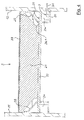
- FIG. 5 The drawing shows the Sieb lakeabites 2 FIG. 3 in cross-section along the section line BB in FIG. 3 , Left and right here are the two side walls 11 and 12 of the machine frame 10 of the screening machine 1 visible in section.
- movably mounted clamping bar 22 is in FIG. 5 visible in view.
- the clamping bar 22 is rigidly connected to the two lateral protective walls 25, suitably by releasable connecting means, such as screws.
- the clamping bar 22 here again visible in section, connected to the clamping bar 22 screen mat 23 runs.
- the spring elements 24 are connected at their top to the lower profile part 26.2 of the cassette frame 20, which in turn is rigidly connected to the side walls 11 and 12. On its underside, the spring elements 24 are connected to the lower portion of the protective walls 25. This results in a vibratory mounting of the clamping bar 22 relative to the cassette frame 20 and the side walls 11 and 12th
- the spring elements 24 shown only schematically here are expediently designed so that they are essentially only one vibration of the clamping bar 22 perpendicular to the plane of the drawing FIG. 5 allow.
- screen mat 23 is clamped in their respective lying between two adjacent clamping bars 21 and 22 areas periodically and relaxed, which leads to an intense movement and loosening of the Siebmatte 23 located Siebguts.
- an effective screening process is promoted within the screening machine 1. It is ensured by the protective walls 25 that no screened material passed through the screen mat 23 can deposit on the spring elements 24 and disturb their function.
- cutouts 14 are provided in each of the two side walls 11 and 12 in the area of the spring elements 24.
- the cutouts 14 are here covered on the outside by means of easily removable, for example pivotable, covers 15, which may consist of a transparent material, such as Plexiglas. Except as observation openings, the cutouts 14 can also be used to replace the respective spring elements 24 in the case of wear or other damage, without having to dismantle further parts of the screening machine 1 and later grown again.
Landscapes
- Combined Means For Separation Of Solids (AREA)
Applications Claiming Priority (1)
| Application Number | Priority Date | Filing Date | Title |
|---|---|---|---|
| DE102014110055.7A DE102014110055B4 (de) | 2014-07-17 | 2014-07-17 | Siebmaschine mit kassettenartigen Siebflächenabschnitten |
Publications (1)
| Publication Number | Publication Date |
|---|---|
| EP2974803A1 true EP2974803A1 (fr) | 2016-01-20 |
Family
ID=53610774
Family Applications (1)
| Application Number | Title | Priority Date | Filing Date |
|---|---|---|---|
| EP15176185.5A Withdrawn EP2974803A1 (fr) | 2014-07-17 | 2015-07-10 | Crible dote de sections de criblage en forme de cassette |
Country Status (2)
| Country | Link |
|---|---|
| EP (1) | EP2974803A1 (fr) |
| DE (1) | DE102014110055B4 (fr) |
Cited By (1)
| Publication number | Priority date | Publication date | Assignee | Title |
|---|---|---|---|---|
| CN108686929A (zh) * | 2018-06-04 | 2018-10-23 | 唐山陆凯科技有限公司 | 一种双层多频复合振动细粒筛分设备 |
Families Citing this family (2)
| Publication number | Priority date | Publication date | Assignee | Title |
|---|---|---|---|---|
| DE102017112108B3 (de) * | 2017-06-01 | 2018-02-22 | Spaleck GmbH & Co. Kommanditgesellschaft | Siebvorrichtung mit Querträgern und daran angebrachten Siebmatten |
| CN107335610B (zh) * | 2017-08-30 | 2022-12-30 | 江苏科选环境科技有限公司 | 新型弹跳筛 |
Citations (6)
| Publication number | Priority date | Publication date | Assignee | Title |
|---|---|---|---|---|
| GB505336A (en) * | 1938-08-25 | 1939-05-09 | Nicola Debono | Improvements in and relating to apparatus for purifying cereal products |
| AT383054B (de) * | 1985-07-24 | 1987-05-11 | Binder Co Ag | Siebvorrichtung |
| EP0496063A2 (fr) * | 1991-01-22 | 1992-07-29 | Hein, Lehmann Trenn- und Fördertechnik GmbH | Surface criblante pour appareil cribleur |
| DE10016979C1 (de) * | 2000-04-06 | 2001-08-30 | Joest Gmbh & Co Kg | Siebvorrichtung |
| EP1228814A2 (fr) * | 2001-02-05 | 2002-08-07 | Binder & Co. Aktiengesellschaft | Dispositif de tamisage |
| WO2004035233A1 (fr) * | 2002-10-17 | 2004-04-29 | Varco I/P, Inc. | Separateur vibrant |
-
2014
- 2014-07-17 DE DE102014110055.7A patent/DE102014110055B4/de active Active
-
2015
- 2015-07-10 EP EP15176185.5A patent/EP2974803A1/fr not_active Withdrawn
Patent Citations (7)
| Publication number | Priority date | Publication date | Assignee | Title |
|---|---|---|---|---|
| GB505336A (en) * | 1938-08-25 | 1939-05-09 | Nicola Debono | Improvements in and relating to apparatus for purifying cereal products |
| AT383054B (de) * | 1985-07-24 | 1987-05-11 | Binder Co Ag | Siebvorrichtung |
| EP0496063A2 (fr) * | 1991-01-22 | 1992-07-29 | Hein, Lehmann Trenn- und Fördertechnik GmbH | Surface criblante pour appareil cribleur |
| EP0496063B1 (fr) | 1991-01-22 | 1994-11-17 | Hein, Lehmann Trenn- und Fördertechnik GmbH | Surface criblante pour appareil cribleur |
| DE10016979C1 (de) * | 2000-04-06 | 2001-08-30 | Joest Gmbh & Co Kg | Siebvorrichtung |
| EP1228814A2 (fr) * | 2001-02-05 | 2002-08-07 | Binder & Co. Aktiengesellschaft | Dispositif de tamisage |
| WO2004035233A1 (fr) * | 2002-10-17 | 2004-04-29 | Varco I/P, Inc. | Separateur vibrant |
Cited By (2)
| Publication number | Priority date | Publication date | Assignee | Title |
|---|---|---|---|---|
| CN108686929A (zh) * | 2018-06-04 | 2018-10-23 | 唐山陆凯科技有限公司 | 一种双层多频复合振动细粒筛分设备 |
| CN108686929B (zh) * | 2018-06-04 | 2024-02-20 | 唐山陆凯科技有限公司 | 一种双层多频复合振动细粒筛分设备 |
Also Published As
| Publication number | Publication date |
|---|---|
| DE102014110055A1 (de) | 2016-01-21 |
| DE102014110055B4 (de) | 2020-03-19 |
Similar Documents
| Publication | Publication Date | Title |
|---|---|---|
| DE69017835T2 (de) | Doppelsieb-Kornklassierungsvorrichtung und Verfahren. | |
| DE102012206347B4 (de) | Siebvorrichtung | |
| DE102013018873B3 (de) | Siebvorrichtung | |
| AT6073U1 (de) | Mehrdecksiebmaschine | |
| DE202014008855U1 (de) | Siebmaschine mit Antrieb | |
| DE202016103754U1 (de) | Siebmaschine | |
| DE102014110055B4 (de) | Siebmaschine mit kassettenartigen Siebflächenabschnitten | |
| EP0405477A1 (fr) | Appareil de tamisage | |
| DE1507741C2 (de) | Selbstreinigendes Sichtersieb für Rüttelsichter | |
| DE1242079B (de) | Siebboden | |
| EP1228814B1 (fr) | Dispositif de tamisage | |
| EP0631825A1 (fr) | Crible à doigts | |
| DE102013107973B3 (de) | Siebmaschine | |
| DE3114573C2 (de) | Siebfeld für Vibrationssiebe | |
| AT400533B (de) | Spannwellensieb | |
| DE2701341A1 (de) | Siebmaschine zur trennung von siebschwierigen materialien | |
| DE1131162B (de) | Siebrost | |
| DE3339605C2 (fr) | ||
| DE102017112108B3 (de) | Siebvorrichtung mit Querträgern und daran angebrachten Siebmatten | |
| DE4323901C2 (de) | Schwingsieb | |
| DE2135323A1 (de) | Schwingsieb, insbesondere schwingsieb fuer die feinabsiebung | |
| EP3917690B1 (fr) | Système de tamis vibrant constitué d'au moins deux machines de tamisage agencées en rangée | |
| DE19944182B4 (de) | Schleifmittelkorn-Siebvorrichtung | |
| EP3241618A1 (fr) | Grille de tamis | |
| DE10361263B3 (de) | Rost zur Vorsortierung |
Legal Events
| Date | Code | Title | Description |
|---|---|---|---|
| PUAI | Public reference made under article 153(3) epc to a published international application that has entered the european phase |
Free format text: ORIGINAL CODE: 0009012 |
|
| AK | Designated contracting states |
Kind code of ref document: A1 Designated state(s): AL AT BE BG CH CY CZ DE DK EE ES FI FR GB GR HR HU IE IS IT LI LT LU LV MC MK MT NL NO PL PT RO RS SE SI SK SM TR |
|
| AX | Request for extension of the european patent |
Extension state: BA ME |
|
| 17P | Request for examination filed |
Effective date: 20160720 |
|
| RBV | Designated contracting states (corrected) |
Designated state(s): AL AT BE BG CH CY CZ DE DK EE ES FI FR GB GR HR HU IE IS IT LI LT LU LV MC MK MT NL NO PL PT RO RS SE SI SK SM TR |
|
| 17Q | First examination report despatched |
Effective date: 20180611 |
|
| STAA | Information on the status of an ep patent application or granted ep patent |
Free format text: STATUS: THE APPLICATION IS DEEMED TO BE WITHDRAWN |
|
| 18D | Application deemed to be withdrawn |
Effective date: 20181023 |