EP2974834A1 - Schneideeinheit zum schneiden eines streifens an verpackungsmaterial mit reversibler einstellvorrichtung zur einstellung der klingenposition - Google Patents
Schneideeinheit zum schneiden eines streifens an verpackungsmaterial mit reversibler einstellvorrichtung zur einstellung der klingenposition Download PDFInfo
- Publication number
- EP2974834A1 EP2974834A1 EP15176335.6A EP15176335A EP2974834A1 EP 2974834 A1 EP2974834 A1 EP 2974834A1 EP 15176335 A EP15176335 A EP 15176335A EP 2974834 A1 EP2974834 A1 EP 2974834A1
- Authority
- EP
- European Patent Office
- Prior art keywords
- supporting body
- adjusting member
- blade
- cutting unit
- slide channel
- Prior art date
- Legal status (The legal status is an assumption and is not a legal conclusion. Google has not performed a legal analysis and makes no representation as to the accuracy of the status listed.)
- Granted
Links
Images






Classifications
-
- B—PERFORMING OPERATIONS; TRANSPORTING
- B26—HAND CUTTING TOOLS; CUTTING; SEVERING
- B26D—CUTTING; DETAILS COMMON TO MACHINES FOR PERFORATING, PUNCHING, CUTTING-OUT, STAMPING-OUT OR SEVERING
- B26D7/00—Details of apparatus for cutting, cutting-out, stamping-out, punching, perforating, or severing by means other than cutting
- B26D7/26—Means for mounting or adjusting the cutting member; Means for adjusting the stroke of the cutting member
- B26D7/2628—Means for adjusting the position of the cutting member
-
- B—PERFORMING OPERATIONS; TRANSPORTING
- B26—HAND CUTTING TOOLS; CUTTING; SEVERING
- B26D—CUTTING; DETAILS COMMON TO MACHINES FOR PERFORATING, PUNCHING, CUTTING-OUT, STAMPING-OUT OR SEVERING
- B26D1/00—Cutting through work characterised by the nature or movement of the cutting member or particular materials not otherwise provided for; Apparatus or machines therefor; Cutting members therefor
- B26D1/01—Cutting through work characterised by the nature or movement of the cutting member or particular materials not otherwise provided for; Apparatus or machines therefor; Cutting members therefor involving a cutting member which does not travel with the work
- B26D1/12—Cutting through work characterised by the nature or movement of the cutting member or particular materials not otherwise provided for; Apparatus or machines therefor; Cutting members therefor involving a cutting member which does not travel with the work having a cutting member moving about an axis
- B26D1/25—Cutting through work characterised by the nature or movement of the cutting member or particular materials not otherwise provided for; Apparatus or machines therefor; Cutting members therefor involving a cutting member which does not travel with the work having a cutting member moving about an axis with a non-circular cutting member
- B26D1/34—Cutting through work characterised by the nature or movement of the cutting member or particular materials not otherwise provided for; Apparatus or machines therefor; Cutting members therefor involving a cutting member which does not travel with the work having a cutting member moving about an axis with a non-circular cutting member moving about an axis parallel to the line of cut
- B26D1/40—Cutting through work characterised by the nature or movement of the cutting member or particular materials not otherwise provided for; Apparatus or machines therefor; Cutting members therefor involving a cutting member which does not travel with the work having a cutting member moving about an axis with a non-circular cutting member moving about an axis parallel to the line of cut and coacting with a rotary member
- B26D1/405—Cutting through work characterised by the nature or movement of the cutting member or particular materials not otherwise provided for; Apparatus or machines therefor; Cutting members therefor involving a cutting member which does not travel with the work having a cutting member moving about an axis with a non-circular cutting member moving about an axis parallel to the line of cut and coacting with a rotary member for thin material, e.g. for sheets, strips or the like
-
- B—PERFORMING OPERATIONS; TRANSPORTING
- B26—HAND CUTTING TOOLS; CUTTING; SEVERING
- B26D—CUTTING; DETAILS COMMON TO MACHINES FOR PERFORATING, PUNCHING, CUTTING-OUT, STAMPING-OUT OR SEVERING
- B26D1/00—Cutting through work characterised by the nature or movement of the cutting member or particular materials not otherwise provided for; Apparatus or machines therefor; Cutting members therefor
- B26D1/56—Cutting through work characterised by the nature or movement of the cutting member or particular materials not otherwise provided for; Apparatus or machines therefor; Cutting members therefor involving a cutting member which travels with the work otherwise than in the direction of the cut, i.e. flying cutter
- B26D1/62—Cutting through work characterised by the nature or movement of the cutting member or particular materials not otherwise provided for; Apparatus or machines therefor; Cutting members therefor involving a cutting member which travels with the work otherwise than in the direction of the cut, i.e. flying cutter and is rotating about an axis parallel to the line of cut, e.g. mounted on a rotary cylinder
- B26D1/626—Cutting through work characterised by the nature or movement of the cutting member or particular materials not otherwise provided for; Apparatus or machines therefor; Cutting members therefor involving a cutting member which travels with the work otherwise than in the direction of the cut, i.e. flying cutter and is rotating about an axis parallel to the line of cut, e.g. mounted on a rotary cylinder for thin material, e.g. for sheets, strips or the like
-
- B—PERFORMING OPERATIONS; TRANSPORTING
- B26—HAND CUTTING TOOLS; CUTTING; SEVERING
- B26D—CUTTING; DETAILS COMMON TO MACHINES FOR PERFORATING, PUNCHING, CUTTING-OUT, STAMPING-OUT OR SEVERING
- B26D7/00—Details of apparatus for cutting, cutting-out, stamping-out, punching, perforating, or severing by means other than cutting
- B26D7/26—Means for mounting or adjusting the cutting member; Means for adjusting the stroke of the cutting member
- B26D2007/2685—Means for mounting or adjusting the cutting member; Means for adjusting the stroke of the cutting member flexible mounting means
Definitions
- the present invention relates to a cutting unit for cutting a strip of packing material.
- strip packing material is used which is unwound from a reel and is then cut into lengths by a cutting unit.
- the cutting unit comprises a cutting drum which is mounted rotatable and supports at its corresponding lateral surface (at least) one first blade, and a contrast element (which may be fixed or rotating as well) coupled to the cutting drum and supporting (at least) a second blade which cooperates with the first blade to cyclically perform the transverse cut of the strip of packing material.
- Both blades are subject to wear and therefore it is necessary to periodically replace them (which usually takes place simultaneously for both blades, i.e. generally both blades that cooperate together are changed at the same time). Once the new blades have been mounted it is necessary to adjust the mutual position of the blades themselves so as to obtain an optimal mechanical coupling that allows performing a precise cut without burrs of the strip of packing material, without, at the same time, subjecting the mechanical members to excessive stress (which produces accelerated wear or even breakage of the blades).
- At least one of the two blades is coupled to a set of adjusting screws which are arranged at a certain distance from each other along the whole extension of the blade; each adjusting screw has a tip that touches (directly or indirectly, or with the interposition of a mechanical return element) the blade to be adjusted and can be screwed to push from the inside the blade to be adjusted towards the other blade.
- the more an adjusting screw is screwed the more the tip of the adjusting screw pushes from the inside on the blade to be adjusted towards the other blade, i.e. moves the blade to be adjusted close to the other blade.
- the operator mounts one blade in a fixed and definitive position onto the corresponding support, while mounting the other blade (to be adjusted) onto the corresponding support in a relatively slack position in order to make an adjustment of the blade position.
- the operator unscrews all the adjusting screws, while after mounting the blade to be adjusted onto the corresponding support the operator proceeds to progressively tighten the adjusting screws so as to adjust the position of the blade to be adjusted with respect to the other blade until obtaining an optimal mechanical coupling between the two blades.
- the patent application EP0318174A2 (in the embodiment illustrated in Figures 11 and 12 ) describes a cutting unit 224 for cutting a strip 16 of paper in a printing machine; the cutting unit 224 comprises: a blade 164; a supporting body 226 having a seat for housing the blade 164; and an adjusting member 246 (in particular a screw), which is inserted (screwed) inside a slide channel 250 formed on the supporting body 226 so as to be able to slide axially along the slide channel 250 itself and is coupled mechanically to the blade 164 housed inside the seat to adjust the position of the blade 164 according to its own axial position along the slide channel 250.
- an adjusting member 246 in particular a screw
- the supporting body 226 is divided into a movable portion 226b in which the seat housing the blade 164 is formed and in a fixed portion 226a adjacent to the movable portion 226b.
- the movable portion 226b of the supporting body 226 is suited to move elastically with respect to the fixed portion 226a of the supporting body 226 by virtue of elastic deformation of a central portion 226C of the supporting body 226.
- the adjusting member 246 generates a variable thrust between the movable portion 226b of the supporting body 226 and the fixed portion 226a moving the movable portion 226b towards the fixed portion 226a starting from a neutral state without elastic deformations of the supporting body 226 and consequently determining an elastic deformation of the supporting body 226.
- the adjusting member 246 allows the movable portion 226b of the supporting body 226 to move closer to the fixed portion 226a (but not to move away from the fixed portion 226a) so as to exploit the elasticity of the supporting body 226 for self-adjusting in use the position of the blade 164 and thus maintaining on the blade 164 a constant contact force with the contrast drum 12 during cutting. Consequently, the function of the adjusting member 246 is to adjust the elastic pre-load of the supporting body 226 to vary (adjust) the contact force that is generated in use between the blade 164 and the contrast drum 12 during cutting.
- the adjusting member 246 is capable of varying (adjusting) the contact force that is generated in use between the blade 164 and the contrast drum 12 during cutting, but it is not able to detect an exact and definite location of the blade 164 during cutting, since when cutting, the supporting body 226 is free to deform elastically under the thrust exerted on the blade 164 by the contrast drum 12.
- the patent application GB2200863A describes a cutting unit provided with a drum 3 supporting the knives 8 and with a further drum 6 acting as an anvil; the radial position of the knives 8 is individually adjustable by means of adjusting means 11.
- the object of the present invention is to provide a cutting unit for cutting a strip of packing material, so that the cutting unit thus is free from the drawbacks described above, i.e. it allows to perform the mutual adjusting position of the two blades for obtaining an optimal mechanical coupling in a simple and fast way, and which, at the same time, is easy and inexpensive to produce.
- number 1 indicates as a whole a station for feeding the packing material to a subsequent packing station 2 (illustrated schematically).
- a strip 3 of packing material is unwound from a reel 4, and then is conveyed through a cutting unit 5 to be cyclically transversely cut so as to separate from the strip 3 of packing material, itself a succession of lengths 6 of packing material which are fed to the packing station 2.
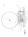
- the cutting unit 5 illustrated schematically in Figure 1 comprises a cutting drum 7 which is mounted rotatable about an axis of rotation 8 and supports at its lateral surface (at least) one blade 9 (of parallelepiped shape as shown in Figure 2 ); furthermore, the cutting unit 5 illustrated schematically in Figure 1 comprises a fixed contrast element 10 (i.e. arranged in a fixed position and therefore without of movement) that is coupled to the cutting drum 7 and supports a blade 11 (of parallelepiped shape as shown in Figure 2 ) which cooperates with the blade 9 to cyclically perform the transverse cut of the strip 3 of packing material.
- a fixed contrast element 10 i.e. arranged in a fixed position and therefore without of movement
- the fixed contrast element 10 comprises a supporting body 12 having a seat 13 which is suited to house the blade 11; in the embodiment illustrated in Figure 2 , the seat 13 is formed inside the supporting body 12, reproduces in negative the shape of the blade 11 and has an opening towards the outside through which an edge of the blade 11 protrudes from the supporting body 12 to cooperate cyclically with the blade 9 carried by the cutting drum 7.
- the supporting body 12 comprises at least one cut 14, which terminates at the seat 13 and generates a localized weakening of the supporting body 12 to allow an elastic deformation of the seat 13.
- Said elastic deformation of the seat 13 allows to temporarily widen the seat 13 in order to allow an axial movement of the blade 11 and also allows to tighten the seat 13 around the blade 11 so as to lock the blade 11 in a fixed position inside the seat 13 itself.
- At least one lock screw (known and not illustrated) is provided, which is screwed inside a corresponding threaded hole formed in the supporting body 12 in proximity to the seat 13 and allows tightening the seat 13 around the blade 11; generally multiple lock screws arranged at a certain distance from each other along the axial extent of the blade 11 are provided.
- the cut 14 may be obtained by means of spark erosion.
- the fixed contrast element 10 comprises at least one adjusting member 15, which is inserted in a slide channel 16 formed in the supporting body 12 so as to slide axially along the slide channel 16 itself.
- the axial position of the adjusting member 15 along the slide channel 16 i.e. the axial movement of the adjusting member 15 along the slide channel 16
- an actuating device 17 that is normally operated manually.
- the adjusting member 15 has a central threaded hole 18 and the actuating device 17 comprises an actuating screw 19, which is screwed inside the threaded hole 18 of the adjusting member 15 and is arranged in an axially fixed position on the supporting body 12 so that rotation of the actuating screw 19 produces a corresponding axial sliding of the adjusting member 15 along the slide channel 16.
- the actuating screw 19 is also housed inside the slide channel 16 and a head of the actuating screw 19 is locked axially between a shoulder of the slide channel 16 and a retaining member 20 on the side opposite the shoulder; in this embodiment, the slide channel 16 is entirely without threads.
- the retaining member 20 has centrally a through hole, through which the head of the actuating screw 19 is reachable from the outside so that a user can rotate the actuating screw 19 by means of a screwdriver in order to translate the adjusting member 15 axially along the slide channel 16.
- the actuating device 17 comprises a locking screw (not shown), which is suited to push radially on the adjusting member 15 to prevent the sliding of the adjusting member 15 along the slide channel 16. Said locking screw is opened, when necessary, to axially translate the adjusting member 15 along the slide channel 16 and is closed once having reached the desired axial position of the adjusting member 15 along the slide channel 16 so as to "freeze" the desired axial position thereof.
- the adjusting member 15 centrally does not have a threaded hole
- the actuating screw 19 is screwed inside the slide channel 16 (which, for this purpose, is at least partially threaded) and has one end resting on the adjusting member 15 so that rotation of the actuating screw 19 produces a corresponding axial sliding of the adjusting member 15 along the slide channel 16 (i.e. the end of the actuating screw 19 pushes on a side of the adjusting member 15).
- the actuating device 17 comprises a return spring, which is arranged in the slide channel 16 on the opposite side to the actuating screw 19 and which pushes the adjusting member 15 towards the actuating screw 19; thanks to the thrust exerted by the return spring, the adjusting member 15 is always in contact with the end of the actuating screw 19.
- the adjusting member 15 is mechanically coupled to the blade 11 housed inside the seat 13 for adjusting the position of the blade 11 according to its own axial position along the slide channel 16; in other words, by moving axially the adjusting member 15 along the slide channel 16 the position of the blade 11 is modified accordingly, i.e. the position of the seat 13 carrying the blade 11 is modified accordingly.
- the supporting body 12 is divided into a movable portion 21 in which the seat 13 housing the blade 11 is formed and a fixed portion 22 adjacent to the movable portion 21.
- the movable portion 21 of the supporting body 12 is suited for moving elastically with respect to the fixed portion 22 by virtue of an elastic deformation of a border area 23 of the supporting body 12 arranged between the movable portion 21 and the fixed portion 22.
- the adjusting member 15 generates a variable thrust (depending on the axial position of the adjusting member 15 along the slide channel 16) between the movable portion 21 of the supporting body 12 and the fixed portion 22 of the supporting body 12 that moves the movable portion 21 away from the fixed portion 22 starting from a neutral state with no elastic deformation of the supporting body 12 and consequently determining an elastic deformation of the supporting body 12.
- the supporting body 12 is locally weakened so as to create a border area 23 dividing the supporting body 12 in a movable portion 21 (in which the seat 13 housing the blade 1 is formed 1) and in a fixed portion 22 and is suited to deform elastically for producing a relative displacement between the movable portion 21 and the fixed portion 22.
- the adjusting member 15 is interposed between the movable portion 21 of the supporting body 12 and the fixed portion 22 of the supporting body 12 to generate a variable thrust (depending on the axial position of the adjusting member 15 along the slide channel 16) moving the movable portion 21 away from the fixed portion 22 starting from a neutral state with no elastic deformation of the supporting body 12 and consequently determining an elastic deformation of the supporting body 12.
- the movement of the adjusting member 15 along the slide channel 16 is suited for moving the movable portion 21 away from the fixed portion 22 creating, consequently, an elastic deformation of the supporting body 12, but the movement of the adjusting member 15 along the slide channel 16 is not able to move (beyond the neutral condition without elastic deformations of the supporting body 12) the movable portion 21 close to the fixed portion 22.
- the adjusting member 15 keeps the movable portion 21 of the supporting body 12 at a given and constant distance from the fixed portion 22 of the supporting body 12 thus preventing the movable portion 21 from moving close to the fixed portion 22; therefore in use the fixed portion 22 of the supporting body 12 (carrying the blade 11) remains in a fixed position, as the contact between the two blades 9 and 11 presses the blade 11, i.e. compresses the blade 11 tending to move the movable portion 21 close to the fixed portion 22 and instead does not apply any type of traction to the blade 11 (i.e. does not tend in any way to further move the movable portion 21 away from the fixed portion 22).
- This characteristic is important to ensure that only an axial sliding of the adjusting member 15 along the slide channel 16 can adjust the position of the blade 11 (i.e. the fixed portion 22 of the supporting body 12 carrying the blade 11); in this way, the adjusting member 15 is usable to adjust the position of the blade 11 until reaching the optimal position of the blade 11 itself.
- the supporting body 12 comprises a pair of cuts 24 separating the movable portion 21 from the fixed portion 22 and delimiting the border area 23; the two cuts 24 are arranged at a certain distance (nonzero) from each other and the border area 23 of the supporting body 12 is bounded by the two cuts 24 (i.e. is comprised between the two cuts 24).
- the supporting body 12 may comprise a single cut 24 separating the movable portion 21 from the fixed portion 22, or may comprise more than two cuts 24 which separate the movable portion 21 from the fixed portion 22.
- the elastic deformation of the border area 23 of the supporting body 12 might not be obtained by means of cuts 24, but by using other weakening means of the supporting body 12.
- the adjusting member 15 has an inclined surface 25, through which the adjusting member 15 varies the position of the blade 11 according to its own axial position along the slide channel 16.
- the adjusting member 15 is wedge-shaped and has on one side the inclined surface 25 through which the adjusting member 25 pushes on the movable portion 21 of the supporting body 12, i.e. the thrust of the adjusting member 15 on the movable portion 21 of the supporting body 12 takes place through the inclined surface 25.
- the inclined surface 25 of the adjusting member 15 pushes on the movable portion 21 of the supporting body 12 along a direction of thrust which is perpendicular to the axial sliding direction of the adjusting member 15 along the slide channel 16.
- the movable portion 21 of the supporting body 12 has an inclined plane 26 which is arranged in contact with the inclined surface 25 of the adjusting member 15; obviously the two inclined surfaces 25 and 26 have identical or at least similar inclinations so as to slide easily one with respect to the other.
- the inclined surface 25 of the adjusting member 15 which pushes (indirectly) on the blade 11 housed inside the seat 13; i.e. the inclined surface 25 of the adjusting member 15 is not in direct contact with the blade 11 housed inside the seat 13, but pushes on the movable portion 21 of the supporting body 12 which carries the seat 13 housing the blade 11 (accordingly, the inclined surface 25 of the adjusting member 15 indirectly pushes on the blade 11 housed inside the seat 13).
- the inclined surface 25 of the adjusting member 15 indirectly pushes on the blade 11 housed inside the seat 13, i.e. the inclined surface 25 of the adjusting member 15 is not in direct contact with the blade 11.
- the inclined surface 25 of the adjusting member 15 pushes directly on the blade 11 housed inside the seat 13, i.e. the inclined surface 25 of the adjusting member 15 is in direct contact with the blade 11.
- only the blade 11 is coupled to the adjusting members 15; alternatively only the blade 9 may be coupled to the adjusting members 15, or both blades 9 and 11 may be coupled to corresponding adjusting members 15.
- a lock screw 27 is illustrated, which is screwed inside a corresponding threaded hole formed on the supporting body 12 (in particular in the movable portion 21 of the supporting body 12) in the vicinity of the seat 13 and it allows the tightening of the seat 13 around the blade 11.
- a locking screw 28 which is suited for pushing radially on the adjusting member 15 to prevent the sliding of the adjusting member 15 along the slide channel 16.
- the locking screw 28 is screwed inside a threaded hole that is arranged perpendicularly to the slide channel 16 and ends inside the slide channel 16 itself; in this way, the tip of the locking screw 28 can press against the slide channel 15 to prevent the sliding of the adjusting member 15 along the slide channel 16.
- the cutting unit 5 illustrated in Figure 3 differs from the cutting unit 5 illustrated in Figure 2 due to the conformation of the main elements and due to the conformation of the actuating device 17.
- the actuating device 17 illustrated in Figure 3 does not comprise the actuating screw 19 which is replaced by a threaded actuating ring nut 29, which is screwed about a threaded portion of the adjusting member 15 and is arranged in an axially fixed position in the supporting body 12 (in particular in the fixed portion 22 of the supporting body 12) so that the rotation of the actuating ring nut 29 determines the corresponding axial sliding of the adjusting member 15 along the slide channel 16.
- the actuating ring nut 29 is inserted inside a housing 30 which is formed on the supporting body 12 and has axially a size (substantially) equal to the size of the actuating ring nut 29.
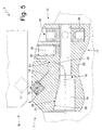
- the cutting unit 5 illustrated in Figures 4 and 5 differs from the cutting unit 5 illustrated in Figure 3 due to the conformation of the main elements and in that it is the blade 9 (and not the blade 11) which is coupled to the adjusting members 15.
- the adjusting members 15 are coupled to the blade 9 carried by the rotatable cutting drum 7, instead of being coupled to the blade 11 carried by the fixed support 10 (as in the cutting unit 5 illustrated in Figure 3 ).
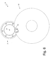
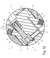
- FIGs 6-13 a further embodiment of the cutting unit 5 described above is illustrated.
- the embodiment illustrated in Figures 6-13 differs from the cutting unit 5 illustrated in Figures 4 and 5 for the conformation of the main elements and for the fact that also the fixed support 10 is mounted to rotate about a corresponding axis of rotation parallel to the axis of rotation 8.
- the cutting drum 7 comprises a pair of twin blades 9 which are arranged in mirror image one with respect to the other and are coupled to corresponding adjusting members 15.
- each blade 9 is tightened on the inside of the corresponding seat 9 by a lock body 31 which is independent and separate from the supporting body 12 and is connected to the supporting body 12 by a plurality of lock screws 27.
- the cutting units 5 comprise both a coupling by means of the inclined surface 25 between the adjusting member 15 and the blade 9 or 11, and an elastic deformability of the supporting body 12.
- a cutting unit 5 could comprise only the inclined surface 25 between the adjusting member 15 and the blade 9 or 11 (i.e. without an elastic deformability from the supporting body 12), or only an elastic deformability of the supporting body 12 (i.e. without the presence of the inclined surface 25 between the adjusting member 15 and the blade 9 or 11).
- the cutting units 5 described above have numerous advantages.
- the cutting units 5 described above allow to adjust in both directions the position of the blade 9 or 11, that is, by axially moving an adjusting member 15 in a direction (turning the corresponding actuating screw 19 or the corresponding actuating ring nut 29) the blade 9 or 11 is moved close to the other blade 11 or 9 (as occurs even in the known cutting units) and by moving axially the adjusting member 15 in the opposite direction (turning the corresponding actuating screw 19 or the corresponding actuating ring nut 29) the blade 9 or 11 is moved away from the other blade 11 or 9 (this condition does not occur in the known cutting unit) thanks to the elasticity in the system that makes bidirectional the movement of the seat 13 housing the blade 9 or 11.
- a blade may be pushed towards the other blade by acting on the corresponding actuating device, but it is never possible to move a blade away from the other blade if not by dismounting and then remounting the blade and starting to adjust the position from the beginning (i.e. by resetting and starting over); in fact, in the known cutting units the actuating device is monodirectional, i.e. is only able to push a blade towards the other blade and is not able to move a blade away from the other blade.
- the actuating device 17 turns out to be bidirectional (reversible), i.e. it is able to both move a blade 9 or 11 towards the other blade 11 or 9, and to move the blade 9 or 11 away from the other blade 11 or 9.
- bidirectionality reversibility
- the cutting units 5 described above allow a very fine adjustment of the position of the blade 9 or 11 thanks to the use of an inclined surface 25, through which the adjusting member 15 varies the position of the blade 9 or 11 as a function of its axial position along the slide channel 16.
- the inclined surface 25 acts as a "reduction gear" of the stroke of the adjusting member 15 since an axial movement of the adjusting member 15 along the slide channel 16 is transformed by the inclined surface 25 in a significantly smaller movement of the movable portion 21 of the supporting body 12 with respect to the fixed portion 22.
- the "gear ratio" of the inclined surface 25 is equal to the tangent of the inclination angle of the inclined surface 25; in the embodiment illustrated in the attached figures, the inclination angle of the inclined surface 25 is between 10 and 15°, and therefore the "gear ratio" of the inclined surface 25 is approximately 3.7-5.7 (i.e. to obtain a displacement of 1 mm of the movable portion 21 of the supporting body 12 with respect to the fixed portion 22 it is necessary that the adjusting member 15 axially translates along the slide channel 16 by approximately 3.7-5.7 mm).
- the cutting units 5 described above are also easy and inexpensive to produce, since they have an overall structure similar to the known cutting unit 5 with respect to which they differ in relatively few details of simple implementation.
- the subdivision of the supporting body 12 in a movable portion 21 and in a fixed portion 22 is achievable with extreme simplicity by performing in supporting body 12 one or two cuts 24 (for example achievable by means of spark erosion or milling in an easy and inexpensive way).
Landscapes
- Life Sciences & Earth Sciences (AREA)
- Forests & Forestry (AREA)
- Engineering & Computer Science (AREA)
- Mechanical Engineering (AREA)
- Details Of Cutting Devices (AREA)
Applications Claiming Priority (1)
| Application Number | Priority Date | Filing Date | Title |
|---|---|---|---|
| ITBO20140409 | 2014-07-16 |
Publications (2)
| Publication Number | Publication Date |
|---|---|
| EP2974834A1 true EP2974834A1 (de) | 2016-01-20 |
| EP2974834B1 EP2974834B1 (de) | 2017-11-01 |
Family
ID=51628224
Family Applications (1)
| Application Number | Title | Priority Date | Filing Date |
|---|---|---|---|
| EP15176335.6A Not-in-force EP2974834B1 (de) | 2014-07-16 | 2015-07-10 | Schneideeinheit zum schneiden eines streifens an verpackungsmaterial mit reversibler einstellvorrichtung zur einstellung der klingenposition |
Country Status (2)
| Country | Link |
|---|---|
| EP (1) | EP2974834B1 (de) |
| JP (1) | JP2016028843A (de) |
Cited By (5)
| Publication number | Priority date | Publication date | Assignee | Title |
|---|---|---|---|---|
| WO2021004767A1 (de) * | 2019-07-05 | 2021-01-14 | Khs Gmbh | Schneidwerk für ein etikettieraggregat sowie etikettieraggregat mit einem solchen schneidwerk |
| CN112776040A (zh) * | 2021-01-18 | 2021-05-11 | 深圳市伟铂瑞信科技有限公司 | 一种多孔密集型背光反射片的多工位同步模切设备 |
| CN113532992A (zh) * | 2021-07-21 | 2021-10-22 | 北京理工大学珠海学院 | 一种土木工程实验的土样制备装置 |
| CN113649822A (zh) * | 2021-08-11 | 2021-11-16 | 一汽解放大连柴油机有限公司 | 一种加工设备及加工方法 |
| IT202000012493A1 (it) * | 2020-05-27 | 2021-11-27 | Gd Spa | Unità di taglio di un nastro di materiale di incarto |
Families Citing this family (1)
| Publication number | Priority date | Publication date | Assignee | Title |
|---|---|---|---|---|
| IT202100004820A1 (it) * | 2021-03-02 | 2022-09-02 | Pe Labellers Spa | Macchina etichettatrice. |
Citations (6)
| Publication number | Priority date | Publication date | Assignee | Title |
|---|---|---|---|---|
| EP0198221A1 (de) * | 1985-03-27 | 1986-10-22 | SASIB S.p.A. | Vorrichtung zum Zerteilen eines endlosen Bandes aus Wickelmaterial in aufeinanderfolgende Einzelabschnitte |
| GB2200863A (en) | 1987-02-05 | 1988-08-17 | Koerber Ag | Apparatus for severing a running web of tipping paper or the like |
| EP0318174A2 (de) | 1987-11-16 | 1989-05-31 | Scheffer, Inc. | Rotierende Schneidvorrichtung |
| WO2011012333A1 (en) * | 2009-07-29 | 2011-02-03 | Sidel S.P.A. | Cutting unit for labelling machines |
| EP2386388A1 (de) * | 2010-05-14 | 2011-11-16 | Hunkeler AG | Vorrichtung zum Querperforieren oder Querschneiden von laufenden Materialbahnen |
| EP2703135A1 (de) * | 2011-04-28 | 2014-03-05 | Pasaban, S.A. | Vorrichtung zum querschneiden von faserstoffbändern |
-
2015
- 2015-07-09 JP JP2015137450A patent/JP2016028843A/ja active Pending
- 2015-07-10 EP EP15176335.6A patent/EP2974834B1/de not_active Not-in-force
Patent Citations (6)
| Publication number | Priority date | Publication date | Assignee | Title |
|---|---|---|---|---|
| EP0198221A1 (de) * | 1985-03-27 | 1986-10-22 | SASIB S.p.A. | Vorrichtung zum Zerteilen eines endlosen Bandes aus Wickelmaterial in aufeinanderfolgende Einzelabschnitte |
| GB2200863A (en) | 1987-02-05 | 1988-08-17 | Koerber Ag | Apparatus for severing a running web of tipping paper or the like |
| EP0318174A2 (de) | 1987-11-16 | 1989-05-31 | Scheffer, Inc. | Rotierende Schneidvorrichtung |
| WO2011012333A1 (en) * | 2009-07-29 | 2011-02-03 | Sidel S.P.A. | Cutting unit for labelling machines |
| EP2386388A1 (de) * | 2010-05-14 | 2011-11-16 | Hunkeler AG | Vorrichtung zum Querperforieren oder Querschneiden von laufenden Materialbahnen |
| EP2703135A1 (de) * | 2011-04-28 | 2014-03-05 | Pasaban, S.A. | Vorrichtung zum querschneiden von faserstoffbändern |
Cited By (5)
| Publication number | Priority date | Publication date | Assignee | Title |
|---|---|---|---|---|
| WO2021004767A1 (de) * | 2019-07-05 | 2021-01-14 | Khs Gmbh | Schneidwerk für ein etikettieraggregat sowie etikettieraggregat mit einem solchen schneidwerk |
| IT202000012493A1 (it) * | 2020-05-27 | 2021-11-27 | Gd Spa | Unità di taglio di un nastro di materiale di incarto |
| CN112776040A (zh) * | 2021-01-18 | 2021-05-11 | 深圳市伟铂瑞信科技有限公司 | 一种多孔密集型背光反射片的多工位同步模切设备 |
| CN113532992A (zh) * | 2021-07-21 | 2021-10-22 | 北京理工大学珠海学院 | 一种土木工程实验的土样制备装置 |
| CN113649822A (zh) * | 2021-08-11 | 2021-11-16 | 一汽解放大连柴油机有限公司 | 一种加工设备及加工方法 |
Also Published As
| Publication number | Publication date |
|---|---|
| EP2974834B1 (de) | 2017-11-01 |
| JP2016028843A (ja) | 2016-03-03 |
Similar Documents
| Publication | Publication Date | Title |
|---|---|---|
| EP2974834B1 (de) | Schneideeinheit zum schneiden eines streifens an verpackungsmaterial mit reversibler einstellvorrichtung zur einstellung der klingenposition | |
| EP3655216B1 (de) | Schleifeinheit für schneidmaschine und maschine mit besagter einheit | |
| EP0077127B1 (de) | Spaltklinge | |
| US4962683A (en) | Rotary cutter apparatus | |
| US10059022B2 (en) | Adjusting device for a pressure roller of a processing machine, particularly a moulding machine, and processing machine, particularly moulding machine, with such an adjusting device | |
| EP2067701B1 (de) | Schneidwerkzeug zum Schneiden von Etiketten | |
| US20120234152A1 (en) | Cutting unit for labelling machines with a multiple-blade rotary drum | |
| US10919169B2 (en) | Machine for cutting logs with grinding wheels and method | |
| US3185010A (en) | Slitting mechanism for endless web material | |
| US6158316A (en) | Contact pressure control method and device for rotary cutter | |
| US20060011015A1 (en) | Sharpening unit and cutting machine comprising at least one blade and said sharpening unit | |
| WO2019016666A1 (en) | GRINDING UNIT FOR CUTTING BLADE, MACHINE COMPRISING SAID UNIT AND ASSOCIATED METHOD | |
| CN107522006B (zh) | 一种可等距调节的胶带分切刀固定装置 | |
| CN1327408A (zh) | 设定切削间隙的装置及方法 | |
| US9278460B2 (en) | Apparatus for the cross-perforation or cross-cutting of continuous material webs | |
| CN110735353B (zh) | 刮刀刀片架系统 | |
| EP1052209A1 (de) | Folienschneideinrichtung insbesondere für eine Wickelmaschine | |
| US4799414A (en) | Rotary cutter apparatus | |
| WO2012077442A1 (ja) | シート状物の切断装置 | |
| EP3399098B1 (de) | Rakelhalter für einen zylinder und system mit einem zylinder und einem rakelhalter | |
| EP3074179B1 (de) | Vorrichtung zum schärfen von klingen | |
| US10633795B2 (en) | Rigid and flexible doctor blade holder and system comprising a cylinder and a doctor blade holder | |
| DE3703463A1 (de) | Schneidvorrichtung zum abtrennen von abschnitten von einem bewegten materialstreifen | |
| CN222511875U (zh) | 用于裁切包装的装置 | |
| CN104261173B (zh) | 一种标纸裁剪装置 |
Legal Events
| Date | Code | Title | Description |
|---|---|---|---|
| PUAI | Public reference made under article 153(3) epc to a published international application that has entered the european phase |
Free format text: ORIGINAL CODE: 0009012 |
|
| AK | Designated contracting states |
Kind code of ref document: A1 Designated state(s): AL AT BE BG CH CY CZ DE DK EE ES FI FR GB GR HR HU IE IS IT LI LT LU LV MC MK MT NL NO PL PT RO RS SE SI SK SM TR |
|
| AX | Request for extension of the european patent |
Extension state: BA ME |
|
| 17P | Request for examination filed |
Effective date: 20160720 |
|
| RBV | Designated contracting states (corrected) |
Designated state(s): AL AT BE BG CH CY CZ DE DK EE ES FI FR GB GR HR HU IE IS IT LI LT LU LV MC MK MT NL NO PL PT RO RS SE SI SK SM TR |
|
| 17Q | First examination report despatched |
Effective date: 20161122 |
|
| REG | Reference to a national code |
Ref country code: DE Ref legal event code: R079 Ref document number: 602015005684 Country of ref document: DE Free format text: PREVIOUS MAIN CLASS: B26D0007260000 Ipc: B26D0001400000 |
|
| GRAP | Despatch of communication of intention to grant a patent |
Free format text: ORIGINAL CODE: EPIDOSNIGR1 |
|
| INTG | Intention to grant announced |
Effective date: 20170425 |
|
| RIC1 | Information provided on ipc code assigned before grant |
Ipc: B26D 1/40 20060101AFI20170407BHEP Ipc: B26D 1/62 20060101ALI20170407BHEP |
|
| GRAS | Grant fee paid |
Free format text: ORIGINAL CODE: EPIDOSNIGR3 |
|
| GRAA | (expected) grant |
Free format text: ORIGINAL CODE: 0009210 |
|
| AK | Designated contracting states |
Kind code of ref document: B1 Designated state(s): AL AT BE BG CH CY CZ DE DK EE ES FI FR GB GR HR HU IE IS IT LI LT LU LV MC MK MT NL NO PL PT RO RS SE SI SK SM TR |
|
| RAP1 | Party data changed (applicant data changed or rights of an application transferred) |
Owner name: G.D SOCIETA PER AZIONI |
|
| REG | Reference to a national code |
Ref country code: GB Ref legal event code: FG4D |
|
| REG | Reference to a national code |
Ref country code: CH Ref legal event code: EP Ref country code: AT Ref legal event code: REF Ref document number: 941604 Country of ref document: AT Kind code of ref document: T Effective date: 20171115 |
|
| REG | Reference to a national code |
Ref country code: IE Ref legal event code: FG4D |
|
| REG | Reference to a national code |
Ref country code: DE Ref legal event code: R096 Ref document number: 602015005684 Country of ref document: DE |
|
| REG | Reference to a national code |
Ref country code: NL Ref legal event code: FP |
|
| REG | Reference to a national code |
Ref country code: LT Ref legal event code: MG4D |
|
| REG | Reference to a national code |
Ref country code: AT Ref legal event code: MK05 Ref document number: 941604 Country of ref document: AT Kind code of ref document: T Effective date: 20171101 |
|
| PG25 | Lapsed in a contracting state [announced via postgrant information from national office to epo] |
Ref country code: LT Free format text: LAPSE BECAUSE OF FAILURE TO SUBMIT A TRANSLATION OF THE DESCRIPTION OR TO PAY THE FEE WITHIN THE PRESCRIBED TIME-LIMIT Effective date: 20171101 Ref country code: FI Free format text: LAPSE BECAUSE OF FAILURE TO SUBMIT A TRANSLATION OF THE DESCRIPTION OR TO PAY THE FEE WITHIN THE PRESCRIBED TIME-LIMIT Effective date: 20171101 Ref country code: SE Free format text: LAPSE BECAUSE OF FAILURE TO SUBMIT A TRANSLATION OF THE DESCRIPTION OR TO PAY THE FEE WITHIN THE PRESCRIBED TIME-LIMIT Effective date: 20171101 Ref country code: NO Free format text: LAPSE BECAUSE OF FAILURE TO SUBMIT A TRANSLATION OF THE DESCRIPTION OR TO PAY THE FEE WITHIN THE PRESCRIBED TIME-LIMIT Effective date: 20180201 Ref country code: ES Free format text: LAPSE BECAUSE OF FAILURE TO SUBMIT A TRANSLATION OF THE DESCRIPTION OR TO PAY THE FEE WITHIN THE PRESCRIBED TIME-LIMIT Effective date: 20171101 |
|
| PG25 | Lapsed in a contracting state [announced via postgrant information from national office to epo] |
Ref country code: AT Free format text: LAPSE BECAUSE OF FAILURE TO SUBMIT A TRANSLATION OF THE DESCRIPTION OR TO PAY THE FEE WITHIN THE PRESCRIBED TIME-LIMIT Effective date: 20171101 Ref country code: IS Free format text: LAPSE BECAUSE OF FAILURE TO SUBMIT A TRANSLATION OF THE DESCRIPTION OR TO PAY THE FEE WITHIN THE PRESCRIBED TIME-LIMIT Effective date: 20180301 Ref country code: RS Free format text: LAPSE BECAUSE OF FAILURE TO SUBMIT A TRANSLATION OF THE DESCRIPTION OR TO PAY THE FEE WITHIN THE PRESCRIBED TIME-LIMIT Effective date: 20171101 Ref country code: LV Free format text: LAPSE BECAUSE OF FAILURE TO SUBMIT A TRANSLATION OF THE DESCRIPTION OR TO PAY THE FEE WITHIN THE PRESCRIBED TIME-LIMIT Effective date: 20171101 Ref country code: BG Free format text: LAPSE BECAUSE OF FAILURE TO SUBMIT A TRANSLATION OF THE DESCRIPTION OR TO PAY THE FEE WITHIN THE PRESCRIBED TIME-LIMIT Effective date: 20180201 Ref country code: HR Free format text: LAPSE BECAUSE OF FAILURE TO SUBMIT A TRANSLATION OF THE DESCRIPTION OR TO PAY THE FEE WITHIN THE PRESCRIBED TIME-LIMIT Effective date: 20171101 Ref country code: GR Free format text: LAPSE BECAUSE OF FAILURE TO SUBMIT A TRANSLATION OF THE DESCRIPTION OR TO PAY THE FEE WITHIN THE PRESCRIBED TIME-LIMIT Effective date: 20180202 |
|
| PG25 | Lapsed in a contracting state [announced via postgrant information from national office to epo] |
Ref country code: EE Free format text: LAPSE BECAUSE OF FAILURE TO SUBMIT A TRANSLATION OF THE DESCRIPTION OR TO PAY THE FEE WITHIN THE PRESCRIBED TIME-LIMIT Effective date: 20171101 Ref country code: DK Free format text: LAPSE BECAUSE OF FAILURE TO SUBMIT A TRANSLATION OF THE DESCRIPTION OR TO PAY THE FEE WITHIN THE PRESCRIBED TIME-LIMIT Effective date: 20171101 Ref country code: CZ Free format text: LAPSE BECAUSE OF FAILURE TO SUBMIT A TRANSLATION OF THE DESCRIPTION OR TO PAY THE FEE WITHIN THE PRESCRIBED TIME-LIMIT Effective date: 20171101 Ref country code: CY Free format text: LAPSE BECAUSE OF FAILURE TO SUBMIT A TRANSLATION OF THE DESCRIPTION OR TO PAY THE FEE WITHIN THE PRESCRIBED TIME-LIMIT Effective date: 20171101 Ref country code: SK Free format text: LAPSE BECAUSE OF FAILURE TO SUBMIT A TRANSLATION OF THE DESCRIPTION OR TO PAY THE FEE WITHIN THE PRESCRIBED TIME-LIMIT Effective date: 20171101 |
|
| REG | Reference to a national code |
Ref country code: DE Ref legal event code: R097 Ref document number: 602015005684 Country of ref document: DE |
|
| PG25 | Lapsed in a contracting state [announced via postgrant information from national office to epo] |
Ref country code: PL Free format text: LAPSE BECAUSE OF FAILURE TO SUBMIT A TRANSLATION OF THE DESCRIPTION OR TO PAY THE FEE WITHIN THE PRESCRIBED TIME-LIMIT Effective date: 20171101 Ref country code: SM Free format text: LAPSE BECAUSE OF FAILURE TO SUBMIT A TRANSLATION OF THE DESCRIPTION OR TO PAY THE FEE WITHIN THE PRESCRIBED TIME-LIMIT Effective date: 20171101 Ref country code: RO Free format text: LAPSE BECAUSE OF FAILURE TO SUBMIT A TRANSLATION OF THE DESCRIPTION OR TO PAY THE FEE WITHIN THE PRESCRIBED TIME-LIMIT Effective date: 20171101 Ref country code: IT Free format text: LAPSE BECAUSE OF FAILURE TO SUBMIT A TRANSLATION OF THE DESCRIPTION OR TO PAY THE FEE WITHIN THE PRESCRIBED TIME-LIMIT Effective date: 20171101 |
|
| PLBE | No opposition filed within time limit |
Free format text: ORIGINAL CODE: 0009261 |
|
| STAA | Information on the status of an ep patent application or granted ep patent |
Free format text: STATUS: NO OPPOSITION FILED WITHIN TIME LIMIT |
|
| 26N | No opposition filed |
Effective date: 20180802 |
|
| PG25 | Lapsed in a contracting state [announced via postgrant information from national office to epo] |
Ref country code: SI Free format text: LAPSE BECAUSE OF FAILURE TO SUBMIT A TRANSLATION OF THE DESCRIPTION OR TO PAY THE FEE WITHIN THE PRESCRIBED TIME-LIMIT Effective date: 20171101 |
|
| REG | Reference to a national code |
Ref country code: CH Ref legal event code: PL |
|
| PG25 | Lapsed in a contracting state [announced via postgrant information from national office to epo] |
Ref country code: MC Free format text: LAPSE BECAUSE OF FAILURE TO SUBMIT A TRANSLATION OF THE DESCRIPTION OR TO PAY THE FEE WITHIN THE PRESCRIBED TIME-LIMIT Effective date: 20171101 Ref country code: LU Free format text: LAPSE BECAUSE OF NON-PAYMENT OF DUE FEES Effective date: 20180710 |
|
| REG | Reference to a national code |
Ref country code: BE Ref legal event code: MM Effective date: 20180731 |
|
| REG | Reference to a national code |
Ref country code: IE Ref legal event code: MM4A |
|
| PG25 | Lapsed in a contracting state [announced via postgrant information from national office to epo] |
Ref country code: FR Free format text: LAPSE BECAUSE OF NON-PAYMENT OF DUE FEES Effective date: 20180731 Ref country code: IE Free format text: LAPSE BECAUSE OF NON-PAYMENT OF DUE FEES Effective date: 20180710 Ref country code: LI Free format text: LAPSE BECAUSE OF NON-PAYMENT OF DUE FEES Effective date: 20180731 Ref country code: CH Free format text: LAPSE BECAUSE OF NON-PAYMENT OF DUE FEES Effective date: 20180731 |
|
| PG25 | Lapsed in a contracting state [announced via postgrant information from national office to epo] |
Ref country code: BE Free format text: LAPSE BECAUSE OF NON-PAYMENT OF DUE FEES Effective date: 20180731 |
|
| PG25 | Lapsed in a contracting state [announced via postgrant information from national office to epo] |
Ref country code: MT Free format text: LAPSE BECAUSE OF NON-PAYMENT OF DUE FEES Effective date: 20180710 |
|
| PG25 | Lapsed in a contracting state [announced via postgrant information from national office to epo] |
Ref country code: TR Free format text: LAPSE BECAUSE OF FAILURE TO SUBMIT A TRANSLATION OF THE DESCRIPTION OR TO PAY THE FEE WITHIN THE PRESCRIBED TIME-LIMIT Effective date: 20171101 |
|
| PG25 | Lapsed in a contracting state [announced via postgrant information from national office to epo] |
Ref country code: PT Free format text: LAPSE BECAUSE OF FAILURE TO SUBMIT A TRANSLATION OF THE DESCRIPTION OR TO PAY THE FEE WITHIN THE PRESCRIBED TIME-LIMIT Effective date: 20171101 |
|
| PG25 | Lapsed in a contracting state [announced via postgrant information from national office to epo] |
Ref country code: HU Free format text: LAPSE BECAUSE OF FAILURE TO SUBMIT A TRANSLATION OF THE DESCRIPTION OR TO PAY THE FEE WITHIN THE PRESCRIBED TIME-LIMIT; INVALID AB INITIO Effective date: 20150710 Ref country code: MK Free format text: LAPSE BECAUSE OF NON-PAYMENT OF DUE FEES Effective date: 20171101 |
|
| PG25 | Lapsed in a contracting state [announced via postgrant information from national office to epo] |
Ref country code: AL Free format text: LAPSE BECAUSE OF FAILURE TO SUBMIT A TRANSLATION OF THE DESCRIPTION OR TO PAY THE FEE WITHIN THE PRESCRIBED TIME-LIMIT Effective date: 20171101 |
|
| PGFP | Annual fee paid to national office [announced via postgrant information from national office to epo] |
Ref country code: NL Payment date: 20200726 Year of fee payment: 6 |
|
| PGFP | Annual fee paid to national office [announced via postgrant information from national office to epo] |
Ref country code: GB Payment date: 20200727 Year of fee payment: 6 |
|
| REG | Reference to a national code |
Ref country code: NL Ref legal event code: MM Effective date: 20210801 |
|
| GBPC | Gb: european patent ceased through non-payment of renewal fee |
Effective date: 20210710 |
|
| PG25 | Lapsed in a contracting state [announced via postgrant information from national office to epo] |
Ref country code: GB Free format text: LAPSE BECAUSE OF NON-PAYMENT OF DUE FEES Effective date: 20210710 |
|
| PG25 | Lapsed in a contracting state [announced via postgrant information from national office to epo] |
Ref country code: NL Free format text: LAPSE BECAUSE OF NON-PAYMENT OF DUE FEES Effective date: 20210801 |
|
| PGFP | Annual fee paid to national office [announced via postgrant information from national office to epo] |
Ref country code: DE Payment date: 20240729 Year of fee payment: 10 |
|
| REG | Reference to a national code |
Ref country code: DE Ref legal event code: R119 Ref document number: 602015005684 Country of ref document: DE |
|
| PG25 | Lapsed in a contracting state [announced via postgrant information from national office to epo] |
Ref country code: DE Free format text: LAPSE BECAUSE OF NON-PAYMENT OF DUE FEES Effective date: 20260203 |