EP2974883B1 - Radlagervorrichtung - Google Patents
Radlagervorrichtung Download PDFInfo
- Publication number
- EP2974883B1 EP2974883B1 EP14764201.1A EP14764201A EP2974883B1 EP 2974883 B1 EP2974883 B1 EP 2974883B1 EP 14764201 A EP14764201 A EP 14764201A EP 2974883 B1 EP2974883 B1 EP 2974883B1
- Authority
- EP
- European Patent Office
- Prior art keywords
- hub wheel
- bolt
- portions
- wheel
- projecting portions
- Prior art date
- Legal status (The legal status is an assumption and is not a legal conclusion. Google has not performed a legal analysis and makes no representation as to the accuracy of the status listed.)
- Active
Links
Images


















Classifications
-
- B—PERFORMING OPERATIONS; TRANSPORTING
- B60—VEHICLES IN GENERAL
- B60B—VEHICLE WHEELS; CASTORS; AXLES FOR WHEELS OR CASTORS; INCREASING WHEEL ADHESION
- B60B27/00—Hubs
- B60B27/0015—Hubs for driven wheels
- B60B27/0036—Hubs for driven wheels comprising homokinetic joints
- B60B27/0042—Hubs for driven wheels comprising homokinetic joints characterised by the fixation of the homokinetic joint to the hub
-
- B—PERFORMING OPERATIONS; TRANSPORTING
- B60—VEHICLES IN GENERAL
- B60B—VEHICLE WHEELS; CASTORS; AXLES FOR WHEELS OR CASTORS; INCREASING WHEEL ADHESION
- B60B27/00—Hubs
- B60B27/0015—Hubs for driven wheels
- B60B27/0021—Hubs for driven wheels characterised by torque transmission means from drive axle
- B60B27/0026—Hubs for driven wheels characterised by torque transmission means from drive axle of the radial type, e.g. splined key
-
- B—PERFORMING OPERATIONS; TRANSPORTING
- B60—VEHICLES IN GENERAL
- B60B—VEHICLE WHEELS; CASTORS; AXLES FOR WHEELS OR CASTORS; INCREASING WHEEL ADHESION
- B60B27/00—Hubs
- B60B27/0005—Hubs with ball bearings
-
- B—PERFORMING OPERATIONS; TRANSPORTING
- B60—VEHICLES IN GENERAL
- B60B—VEHICLE WHEELS; CASTORS; AXLES FOR WHEELS OR CASTORS; INCREASING WHEEL ADHESION
- B60B27/00—Hubs
- B60B27/0015—Hubs for driven wheels
- B60B27/0036—Hubs for driven wheels comprising homokinetic joints
-
- F—MECHANICAL ENGINEERING; LIGHTING; HEATING; WEAPONS; BLASTING
- F16—ENGINEERING ELEMENTS AND UNITS; GENERAL MEASURES FOR PRODUCING AND MAINTAINING EFFECTIVE FUNCTIONING OF MACHINES OR INSTALLATIONS; THERMAL INSULATION IN GENERAL
- F16C—SHAFTS; FLEXIBLE SHAFTS; ELEMENTS OR CRANKSHAFT MECHANISMS; ROTARY BODIES OTHER THAN GEARING ELEMENTS; BEARINGS
- F16C35/00—Rigid support of bearing units; Housings, e.g. caps, covers
- F16C35/04—Rigid support of bearing units; Housings, e.g. caps, covers in the case of ball or roller bearings
- F16C35/06—Mounting or dismounting of ball or roller bearings; Fixing them onto shaft or in housing
- F16C35/063—Fixing them on the shaft
- F16C35/0635—Fixing them on the shaft the bore of the inner ring being of special non-cylindrical shape which co-operates with a complementary shape on the shaft, e.g. teeth, polygonal sections
-
- F—MECHANICAL ENGINEERING; LIGHTING; HEATING; WEAPONS; BLASTING
- F16—ENGINEERING ELEMENTS AND UNITS; GENERAL MEASURES FOR PRODUCING AND MAINTAINING EFFECTIVE FUNCTIONING OF MACHINES OR INSTALLATIONS; THERMAL INSULATION IN GENERAL
- F16D—COUPLINGS FOR TRANSMITTING ROTATION; CLUTCHES; BRAKES
- F16D1/00—Couplings for rigidly connecting two coaxial shafts or other movable machine elements
- F16D1/06—Couplings for rigidly connecting two coaxial shafts or other movable machine elements for attachment of a member on a shaft or on a shaft-end
- F16D1/076—Couplings for rigidly connecting two coaxial shafts or other movable machine elements for attachment of a member on a shaft or on a shaft-end by clamping together two faces perpendicular to the axis of rotation, e.g. with bolted flanges
-
- F—MECHANICAL ENGINEERING; LIGHTING; HEATING; WEAPONS; BLASTING
- F16—ENGINEERING ELEMENTS AND UNITS; GENERAL MEASURES FOR PRODUCING AND MAINTAINING EFFECTIVE FUNCTIONING OF MACHINES OR INSTALLATIONS; THERMAL INSULATION IN GENERAL
- F16B—DEVICES FOR FASTENING OR SECURING CONSTRUCTIONAL ELEMENTS OR MACHINE PARTS TOGETHER, e.g. NAILS, BOLTS, CIRCLIPS, CLAMPS, CLIPS OR WEDGES; JOINTS OR JOINTING
- F16B39/00—Locking of screws, bolts or nuts
- F16B39/02—Locking of screws, bolts or nuts in which the locking takes place after screwing down
- F16B39/10—Locking of screws, bolts or nuts in which the locking takes place after screwing down by a plate, spring, wire or ring immovable with regard to the bolt or object and mainly perpendicular to the axis of the bolt
- F16B39/103—Locking of screws, bolts or nuts in which the locking takes place after screwing down by a plate, spring, wire or ring immovable with regard to the bolt or object and mainly perpendicular to the axis of the bolt with a locking cup washer, ring or sleeve surrounding the nut or bolt head and being partially deformed on the nut or bolt head, or on the object itself
- F16B39/105—Locking of screws, bolts or nuts in which the locking takes place after screwing down by a plate, spring, wire or ring immovable with regard to the bolt or object and mainly perpendicular to the axis of the bolt with a locking cup washer, ring or sleeve surrounding the nut or bolt head and being partially deformed on the nut or bolt head, or on the object itself locking the bold head or nut into a hole or cavity, e.g. with the cup washer, ring or sleeve deformed into a dimple in the cavity
-
- F—MECHANICAL ENGINEERING; LIGHTING; HEATING; WEAPONS; BLASTING
- F16—ENGINEERING ELEMENTS AND UNITS; GENERAL MEASURES FOR PRODUCING AND MAINTAINING EFFECTIVE FUNCTIONING OF MACHINES OR INSTALLATIONS; THERMAL INSULATION IN GENERAL
- F16C—SHAFTS; FLEXIBLE SHAFTS; ELEMENTS OR CRANKSHAFT MECHANISMS; ROTARY BODIES OTHER THAN GEARING ELEMENTS; BEARINGS
- F16C19/00—Bearings with rolling contact, for exclusively rotary movement
- F16C19/02—Bearings with rolling contact, for exclusively rotary movement with bearing balls essentially of the same size in one or more circular rows
- F16C19/14—Bearings with rolling contact, for exclusively rotary movement with bearing balls essentially of the same size in one or more circular rows for both radial and axial load
- F16C19/18—Bearings with rolling contact, for exclusively rotary movement with bearing balls essentially of the same size in one or more circular rows for both radial and axial load with two or more rows of balls
- F16C19/181—Bearings with rolling contact, for exclusively rotary movement with bearing balls essentially of the same size in one or more circular rows for both radial and axial load with two or more rows of balls with angular contact
- F16C19/183—Bearings with rolling contact, for exclusively rotary movement with bearing balls essentially of the same size in one or more circular rows for both radial and axial load with two or more rows of balls with angular contact with two rows at opposite angles
- F16C19/184—Bearings with rolling contact, for exclusively rotary movement with bearing balls essentially of the same size in one or more circular rows for both radial and axial load with two or more rows of balls with angular contact with two rows at opposite angles in O-arrangement
- F16C19/186—Bearings with rolling contact, for exclusively rotary movement with bearing balls essentially of the same size in one or more circular rows for both radial and axial load with two or more rows of balls with angular contact with two rows at opposite angles in O-arrangement with three raceways provided integrally on parts other than race rings, e.g. third generation hubs
-
- F—MECHANICAL ENGINEERING; LIGHTING; HEATING; WEAPONS; BLASTING
- F16—ENGINEERING ELEMENTS AND UNITS; GENERAL MEASURES FOR PRODUCING AND MAINTAINING EFFECTIVE FUNCTIONING OF MACHINES OR INSTALLATIONS; THERMAL INSULATION IN GENERAL
- F16C—SHAFTS; FLEXIBLE SHAFTS; ELEMENTS OR CRANKSHAFT MECHANISMS; ROTARY BODIES OTHER THAN GEARING ELEMENTS; BEARINGS
- F16C19/00—Bearings with rolling contact, for exclusively rotary movement
- F16C19/52—Bearings with rolling contact, for exclusively rotary movement with devices affected by abnormal or undesired conditions
- F16C19/527—Bearings with rolling contact, for exclusively rotary movement with devices affected by abnormal or undesired conditions related to vibration and noise
-
- F—MECHANICAL ENGINEERING; LIGHTING; HEATING; WEAPONS; BLASTING
- F16—ENGINEERING ELEMENTS AND UNITS; GENERAL MEASURES FOR PRODUCING AND MAINTAINING EFFECTIVE FUNCTIONING OF MACHINES OR INSTALLATIONS; THERMAL INSULATION IN GENERAL
- F16C—SHAFTS; FLEXIBLE SHAFTS; ELEMENTS OR CRANKSHAFT MECHANISMS; ROTARY BODIES OTHER THAN GEARING ELEMENTS; BEARINGS
- F16C2226/00—Joining parts; Fastening; Assembling or mounting parts
- F16C2226/50—Positive connections
- F16C2226/60—Positive connections with threaded parts, e.g. bolt and nut connections
-
- F—MECHANICAL ENGINEERING; LIGHTING; HEATING; WEAPONS; BLASTING
- F16—ENGINEERING ELEMENTS AND UNITS; GENERAL MEASURES FOR PRODUCING AND MAINTAINING EFFECTIVE FUNCTIONING OF MACHINES OR INSTALLATIONS; THERMAL INSULATION IN GENERAL
- F16C—SHAFTS; FLEXIBLE SHAFTS; ELEMENTS OR CRANKSHAFT MECHANISMS; ROTARY BODIES OTHER THAN GEARING ELEMENTS; BEARINGS
- F16C2326/00—Articles relating to transporting
- F16C2326/01—Parts of vehicles in general
- F16C2326/02—Wheel hubs or castors
-
- F—MECHANICAL ENGINEERING; LIGHTING; HEATING; WEAPONS; BLASTING
- F16—ENGINEERING ELEMENTS AND UNITS; GENERAL MEASURES FOR PRODUCING AND MAINTAINING EFFECTIVE FUNCTIONING OF MACHINES OR INSTALLATIONS; THERMAL INSULATION IN GENERAL
- F16D—COUPLINGS FOR TRANSMITTING ROTATION; CLUTCHES; BRAKES
- F16D1/00—Couplings for rigidly connecting two coaxial shafts or other movable machine elements
- F16D1/06—Couplings for rigidly connecting two coaxial shafts or other movable machine elements for attachment of a member on a shaft or on a shaft-end
- F16D1/064—Couplings for rigidly connecting two coaxial shafts or other movable machine elements for attachment of a member on a shaft or on a shaft-end non-disconnectable
- F16D1/072—Couplings for rigidly connecting two coaxial shafts or other movable machine elements for attachment of a member on a shaft or on a shaft-end non-disconnectable involving plastic deformation
-
- F—MECHANICAL ENGINEERING; LIGHTING; HEATING; WEAPONS; BLASTING
- F16—ENGINEERING ELEMENTS AND UNITS; GENERAL MEASURES FOR PRODUCING AND MAINTAINING EFFECTIVE FUNCTIONING OF MACHINES OR INSTALLATIONS; THERMAL INSULATION IN GENERAL
- F16D—COUPLINGS FOR TRANSMITTING ROTATION; CLUTCHES; BRAKES
- F16D1/00—Couplings for rigidly connecting two coaxial shafts or other movable machine elements
- F16D1/10—Quick-acting couplings in which the parts are connected by simply bringing them together axially
- F16D2001/103—Quick-acting couplings in which the parts are connected by simply bringing them together axially the torque is transmitted via splined connections
-
- F—MECHANICAL ENGINEERING; LIGHTING; HEATING; WEAPONS; BLASTING
- F16—ENGINEERING ELEMENTS AND UNITS; GENERAL MEASURES FOR PRODUCING AND MAINTAINING EFFECTIVE FUNCTIONING OF MACHINES OR INSTALLATIONS; THERMAL INSULATION IN GENERAL
- F16D—COUPLINGS FOR TRANSMITTING ROTATION; CLUTCHES; BRAKES
- F16D3/00—Yielding couplings, i.e. with means permitting movement between the connected parts during the drive
- F16D3/16—Universal joints in which flexibility is produced by means of pivots or sliding or rolling connecting parts
- F16D3/20—Universal joints in which flexibility is produced by means of pivots or sliding or rolling connecting parts one coupling part entering a sleeve of the other coupling part and connected thereto by sliding or rolling members
- F16D3/22—Universal joints in which flexibility is produced by means of pivots or sliding or rolling connecting parts one coupling part entering a sleeve of the other coupling part and connected thereto by sliding or rolling members the rolling members being balls, rollers, or the like, guided in grooves or sockets in both coupling parts
- F16D3/223—Universal joints in which flexibility is produced by means of pivots or sliding or rolling connecting parts one coupling part entering a sleeve of the other coupling part and connected thereto by sliding or rolling members the rolling members being balls, rollers, or the like, guided in grooves or sockets in both coupling parts the rolling members being guided in grooves in both coupling parts
- F16D2003/22326—Attachments to the outer joint member, i.e. attachments to the exterior of the outer joint member or to the shaft of the outer joint member
Definitions
- the present invention relates to a method for assembling a bearing device for a wheel configured to rotatably support a driving wheel (front wheel of a front-engine front-drive (FF) vehicle, rear wheel of a front-engine rear-drive (FR) vehicle, and all wheels of a four-wheel drive (4WD) vehicle) with respect to a suspension device for an automobile, for example.
- a driving wheel front wheel of a front-engine front-drive (FF) vehicle, rear wheel of a front-engine rear-drive (FR) vehicle, and all wheels of a four-wheel drive (4WD) vehicle
- the related-art bearing device for a wheel includes, as main components thereof, a constant velocity universal joint 107, and a wheel bearing 106 including a hub wheel 101, an inner ring 102, double-row balls 103 and 104, and an outer ring 105.
- the hub wheel 101 has an inner raceway surface 108 on an outboard side formed on an outer peripheral surface thereof, and includes a wheel mounting flange 109 for allowing a wheel (not shown) to be mounted thereto.
- Hub bolts 110 for fixing a wheel disc are equiangularly embedded in the wheel mounting flange 109.
- the inner ring 102 is fitted to a small-diameter step portion 111 formed on an outer peripheral surface of the hub wheel 101 on an inboard side, and an inner raceway surface 112 on the inboard side is formed on an outer peripheral surface of the inner ring 102.
- a female spline 113 for coupling the constant velocity universal joint 107 to allow torque transmission therebetween is formed on an inner peripheral surface of a shaft hole of the hub wheel 101.
- the inner ring 102 is press-fitted with adequate interference for the purpose of preventing creep.
- the inner raceway surface 108 on the outboard side that is formed on the outer peripheral surface of the hub wheel 101 and the inner raceway surface 112 on the inboard side that is formed on the outer peripheral surface of the inner ring 102 constitute double-row inner raceway surfaces.
- the inner ring 102 is press-fitted into the small-diameter step portion 111 of the hub wheel 101, and an end portion of the small-diameter step portion 111 is crimped outward. As a result, the inner ring 102 is retained by a crimped portion 114 thus formed and integrated with the hub wheel 101, to thereby apply preload to the wheel bearing 106.
- the outer ring 105 has double-row outer raceway surfaces 115 and 116 formed on an inner peripheral surface thereof and opposed to the inner raceway surfaces 108 and 112 of the hub wheel 101 and the inner ring 102.
- the outer ring 105 has a vehicle body mounting flange 117 for mounting the wheel bearing 106 to a vehicle body (not shown) on an outer peripheral surface thereof.
- the vehicle body mounting flange 117 is fixed to a knuckle extending from a suspension device (not shown) of the vehicle body with a bolt or the like by using a mounting hole 118.
- the wheel bearing 106 has a double-row angular ball bearing structure. That is, the balls 103 and 104 are interposed between the inner raceway surfaces 108 and 112 formed on the outer peripheral surfaces of the hub wheel 101 and the inner ring 102 and the outer raceway surfaces 115 and 116 formed on the inner peripheral surface of the outer ring 105. Then, the balls 103 and 104 in respective rows are equiangularly supported by cages 119 and 120.
- a pair of seals 121 and 122 for sealing annular spaces between the outer ring 105 and the hub wheel 101 and between the outer ring 105 and the inner ring 102 are fitted to the inner diameter at both end portions of the outer ring 105. With this, leakage of lubricant such as grease filled inside and entrance of water and foreign matter from the outside are prevented.
- the bearing device for a wheel is configured by coupling an outer joint member 123 of the constant velocity universal joint 107 to the hub wheel 101.
- the outer joint member 123 includes a cup-shaped mouth section 124 that accommodates internal components (not shown) such as an inner joint member, balls, and a cage, and a stem section 125 that integrally extends from the mouth section 124 in an axial direction.
- a male spline 126 for coupling the stem section 125 to the hub wheel 101 to allow torque transmission therebetween is formed.
- the stem section 125 of the outer joint member 123 is press-fitted into the shaft hole of the hub wheel 101 so that a nut 127 is threadedly engaged with a male thread portion 129 formed at an end portion of the stem section 125. Then, by fastening the nut 127 in a state of being locked to an end surface of the hub wheel 101, the constant velocity universal joint 107 is fixed to the hub wheel 101. A shoulder portion 128 of the outer joint member 123 is brought into abutment against the crimped portion 114 of the hub wheel 101 by a fastening force (axial force) of the nut 127. In this manner, the male spline 126 of the stem section 125 and the female spline 113 of the hub wheel 101 are fitted to each other. As a result, the torque transmission from the constant velocity universal joint 107 to the wheel bearing 106 is enabled.
- the crimped portion 114 of the hub wheel 101 and the shoulder portion 128 of the outer joint member 123, which is opposed to the crimped portion 114, are in a state of abutment against each other by the fastening force (axial force) of the nut 127.
- the rotational torque is to be transmitted from the outer joint member 123 to the hub wheel 101 through an intermediation of the female spline 113 and the male spline 126.
- Patent Literature 1 As means for preventing the stick-slip noise, means for increasing a frictional resistance on contact surfaces of the crimped portion 114 of the hub wheel 101 and the shoulder portion 128 of the outer joint member 123 has been taken so as not to cause the sudden slippage (see Patent Literature 1, for example).
- the means for increasing the frictional resistance a structure in which radial, oval, or cross-hatched projecting and depressed portions are formed on the contact surface of the shoulder portion 128 of the outer joint member 123 and a structure in which a spacer made of rubber or resin is provided on the contact surface of the shoulder portion 128 of the outer joint member 123.
- Patent Literature 2 As another means for preventing the stick-slip noise, means for reducing the frictional resistance on the contact surfaces of the crimped portion 114 of the hub wheel 101 and the shoulder portion 128 of the outer joint member 123 has been taken so as not to cause the sudden slippage (see Patent Literature 2, for example) .
- Patent Literature 2 there is disclosed a structure in which a depressed groove is formed on the contact surface of the crimped portion 114 of the hub wheel 101 and the depressed groove is filled with grease.
- patent literature 3 an universal joint assembly is disclosed. Therein the inner and outer member are press-fitted by tightening a screw. During the assembling, projections on the inner member and recesses on the outer member interfere completely with one an other.
- the projecting and depressed portions need to be formed on the contact surface of the shoulder portion 128 of the outer joint member 123 or the spacer needs to be provided.
- the depressed groove needs to be formed on the contact surface of the crimped portion 114 of the hub wheel 101. As described above, the formation of the projecting and depressed portions or the formation of the depressed groove is required, or the spacer as an independent member is required as a process of changing the frictional resistance on the contact surface. Therefore, there is a problem in that cost rises of the bearing device for a wheel are caused.
- the present invention has been proposed in view of the problem described above, and has an object to provide a bearing device for a wheel, capable of preventing stick-slip noise by simple means without requiring a process of changing a frictional resistance on a contact surface.
- the plurality of projecting portions extending in the axial direction are formed on the stem section of the outer joint member, and the depressed portions having the interference with respect to the projecting portions are formed in advance on the hub wheel of the outer joint member.
- One of the hub wheel and the stem section of the outer joint member is press-fitted into the other, to thereby provide the projection and depression fitting structure in which the projecting portions and the depressed portions are brought into close contact with each other at the entire fitting contact portion therebetween.
- a depressed-portion forming surface is extremely slightly cut by the projecting portions, and the shape of the projecting portions is transferred to the depressed-portion forming surface on a mating side while concomitantly involving extremely small plastic deformation or elastic deformation of the depressed-portion forming surface by the projecting portions.
- the projecting portions dig into the depressed-portion forming surface on the mating side so that the inner diameter of the hub wheel is slightly increased.
- relative movement of the projecting portions in the axial direction is allowed in this state.
- the inner diameter of the hub wheel is reduced to recover the original diameter.
- the projecting portions and the depressed portions are brought into close contact with each other at the entire fitting contact portion therebetween, with the result that the outer joint member and the hub wheel can firmly be coupled to and integrated with each other.
- the depressed portions having the interference with respect to the projecting portions are formed in advance. Therefore, the outer joint member can be press-fitted into the hub wheel with a force equal to or smaller than the axial force generated by screw fastening. As a result, there is no need to separately prepare a dedicated jig when press-fitting the stem section of the outer joint member into the hub wheel.
- the constant velocity universal joint can easily be coupled to the wheel bearing by the screw fastening using a component of the bearing device for a wheel.
- the difference between the axial force generated by the screw fastening and the axial force generated by the press-fitting force is set to 32 kN or smaller.
- the difference between the axial force generated by the screw fastening and the axial force generated by the press-fitting force that is, the axial force generated on contact surfaces of the end portion of the inner member and the shoulder portion of the outer joint member is set to 32 kN or smaller.
- the screw fastening structure of the present invention may be a structure comprising: a female thread portion formed at an axial end of the stem section of the outer joint member; and a male thread portion to be locked at the hub wheel in a state of being threadedly engaged with the female thread portion.
- the male thread portion is threadedly engaged with the female thread portion of the stem section, and is therefore fastened in a state of being locked at the hub wheel, to thereby fix the constant velocity universal joint to the hub wheel.
- the plurality of projecting portions are provided on the stem section of the outer joint member, and the plurality of depressed portions be provided on the hub wheel.
- a value obtained by dividing an axial length from the shoulder portion of the outer joint member, against which the end portion of the inner member abuts, to the plurality of projecting portions by a maximum outer diameter of the stem section is set to 0.3 or smaller, and that a value obtained by dividing an axial length of the stem section by the maximum outer diameter of the stem section is set to 1.3 or smaller.
- the bearing device for a wheel has a configuration in which the hub wheel and the outer joint member of the constant velocity universal joint are fastened through an intermediation of a bolt, it is desired that rotation of the bolt in a loosening direction be regulated between a head portion of the bolt and the hub wheel. In this manner, a fastened state of the hub wheel and the constant velocity universal joint can be maintained over a long period of time. Thus, inconvenience such as generation of abnormal noise and acceleration of wear due to loosening of the fastened bolt can be suppressed.
- the hub wheel may comprise an engagement portion, and the head portion of the bolt may comprise a loosening prevention member engageable with the engagement portion mounted thereon.
- the engagement portion may comprise a protruding portion or a recessed portion
- the loosening prevention member may be configured to be engageable with the engagement portion by being crimped at a position of the engagement portion or in a vicinity thereof.
- the engagement portion may comprise a protruding portion or a recessed portion
- the loosening prevention member may comprise a projecting portion or a depressed portion engageable with the engagement portion
- the loosening prevention member may comprise a cap member mountable onto the head portion of the bolt through press fitting.
- the loosening prevention member may comprise a clip member having an opening portion in a part in a peripheral direction.
- the clip member is mountable onto the head portion of the bolt through elastic deformation of the opening portion in an enlarged manner.
- the hub wheel may comprise an engagement portion, and the head portion of the bolt may comprise a flange portion engageable with the engagement portion.
- the engagement portion may comprise a protruding portion or a recessed portion, and the flange portion may be configured to be engageable with the engagement portion by being crimped at a position of the engagement portion or in a vicinity thereof.
- the head portion of the bolt may be fixed to the hub wheel by welding.
- the plurality of projecting portions formed on the stem section of the outer joint member to extend in the axial direction are press-fitted into the other having the plurality of depressed portions formed to have the interference with respect to the projecting portions.
- the shape of the projecting portions is transferred to the other to provide the projection and depression fitting structure in which the projecting portion and the depressed portions are brought into close contact with each other at the entire fitting contact portion therebetween.
- the depressed portions having the interference with respect to the projecting portions are formed in advance. Therefore, the outer joint member can be press-fitted into the hub wheel with the force equal to or smaller than the axial force generated by the screw fastening.
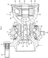
- a bearing device for a wheel illustrated in FIG. 1 comprises, as main components thereof, a constant velocity universal joint 7, and a wheel bearing 6 comprising a hub wheel 1 and an inner ring 2 that serve as an inner member, double-row balls 3 and 4, and an outer ring 5 that serves as an outer member.
- a bearing device for a wheel illustrated in FIG. 1 comprises, as main components thereof, a constant velocity universal joint 7, and a wheel bearing 6 comprising a hub wheel 1 and an inner ring 2 that serve as an inner member, double-row balls 3 and 4, and an outer ring 5 that serves as an outer member.
- an outer side of a vehicle body in a state in which the bearing device for a wheel is mounted to the vehicle body is referred to as an outboard side (left side in the figures), and a middle side of the vehicle body is referred to as an inboard side (right side in the figures).
- the hub wheel 1 has an inner raceway surface 8 on the outboard side formed on an outer peripheral surface thereof, and comprises a wheel mounting flange 9 for allowing a wheel (not shown) to be mounted thereto.
- Hub bolts 10 for fixing a wheel disc are equiangularly embedded in the wheel mounting flange 9.
- the inner ring 2 is fitted to a small-diameter step portion 11 formed on an outer peripheral surface of the hub wheel 1 on the inboard side, and an inner raceway surface 12 on the inboard side is formed on an outer peripheral surface of the inner ring 2.
- the inner ring 2 is press-fitted with adequate interference for the purpose of preventing creep.
- the inner raceway surface 8 on the outboard side that is formed on the outer peripheral surface of the hub wheel 1 and the inner raceway surface 12 on the inboard side that is formed on the outer peripheral surface of the inner ring 2 constitute double-row raceway surfaces.
- the inner ring 2 is press-fitted into the small-diameter step portion 11 of the hub wheel 1, and the end portion of the small-diameter step portion 11 is crimped outward by orbital forming. As a result, the inner ring 2 is retained by a crimped portion 13 thus formed and integrated with the hub wheel 1, to thereby apply preload to the wheel bearing 6.
- the outer ring 5 has double-row outer raceway surfaces 14 and 15 formed on an inner peripheral surface thereof, which are respectively opposed to the inner raceway surface 8 formed on the hub wheel 1 and the inner raceway surface 12 formed on the inner ring 2.
- the outer ring 5 has a vehicle body mounting flange 16 for mounting the wheel bearing 6 to a vehicle body (not shown) on an outer peripheral surface thereof.
- the vehicle body mounting flange 16 is fixed to a knuckle extending from a suspension device (not shown) of the vehicle body with a bolt or the like by using a mounting hole 17.
- the wheel bearing 6 has a double-row angular ball bearing structure. That is, the balls 3 and 4 are interposed between the inner raceway surfaces 8 and 12 formed on the outer peripheral surfaces of the hub wheel 1 and the inner ring 2 and the outer raceway surfaces 14 and 15 formed on the inner peripheral surface of the outer ring 5. Thus, the balls 3 and 4 in respective rows are equiangularly supported by cages 18 and 19. Note that, the wheel bearing 6 has a structure integrated with the hub wheel 1 by retaining the inner ring 2 by the crimped portion 13 and therefore, is separable from an outer joint member 20 of the constant velocity universal joint 7.
- a pair of seals 21 and 22 for sealing annular spaces between the outer ring 5 and the hub wheel 1 and between the outer ring 5 and the inner ring 2 are provided.
- the seals 21 and 22 are fitted to the inner diameter at both end portions of the outer ring 5 so as to prevent leakage of a lubricant such as grease filled inside and entrance of water and foreign matter from the outside.
- the seal 21 comprises a cored bar and an elastic member. A distal end of a lip of the elastic member is held in sliding-contact with the outer peripheral surface of the hub wheel 1.
- the type of the seal 22 is called "pack seal".
- the seal 22 comprises two L-shaped cored bars and an elastic member. The elastic member is mounted to one of the cored bars, whereas the distal end of the lip of the elastic member is held in sliding-contact with an outer peripheral surface of another of the cored bars, which is mounted to an outer periphery of the inner ring.
- the constant velocity universal joint 7 is a fixed type constant velocity universal joint that is provided to one end of a shaft 23 constituting a drive shaft and allows only an angular displacement between two shafts on a driving side and a driven side.
- the constant velocity universal joint 7 comprises the outer joint member 20 having track grooves 24 formed in an inner peripheral surface thereof, an inner joint member 26 having track grooves 25 formed in an outer peripheral surface thereof so as to be opposed to the track grooves 24 of the outer joint member 20, balls 27 built into spaces between the track grooves 24 of the outer joint member 20 and the track grooves 25 of the inner joint member 26, and a cage 28 interposed between the inner peripheral surface of the outer joint member 20 and the outer peripheral surface of the inner joint member 26 to retain the balls 27.
- the outer joint member 20 comprises a cup-shaped mouth section 29 that accommodates internal components such as the inner joint member 26, the balls 27, and the cage 28, and a stem section 30 that integrally extends from the mouth section 29 in an axial direction.
- An axial end of the shaft 23 is press-fitted into the inner joint member 26, and is coupled to the shaft 23 by spline fitting to allow torque transmission therebetween.
- a bellows-like boot 31 made of a resin is mounted between the outer joint member 20 of the constant velocity universal joint 7 and the shaft 23 to prevent leakage of a lubricant such as grease filled inside the joint, and to prevent entrance of foreign matter from outside the joint, thereby attaining a structure of closing an opening portion of the outer joint member 20 with the boot 31.
- the boot 31 comprises a large-diameter end portion fastened and fixed with a boot band on an outer peripheral surface of the outer joint member 20, a small-diameter end portion fastened and fixed with a boot band on an outer peripheral surface of the shaft 23, and a flexible bellows portion connecting the large-diameter end portion and the small-diameter end portion, and reduced in diameter as approaching from the large-diameter end portion toward the small-diameter end portion.
- a base portion 32 of the stem section 30 of the outer joint member 20 is formed to have a columnar shape, and a male spline comprising a plurality of projecting portions 33 extending in the axial direction is formed on an outer peripheral surface on the outboard side with respect to the base portion 32.
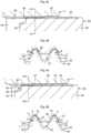
- a distal end portion 35 of a shaft hole 34 of the hub wheel 1 is formed to have a cylindrical shape, and a plurality of depressed portions 36 having an interference n with respect only to a peripheral side wall portion 71 (see FIG. 5B ) of each of the projecting portions 33 described above are formed on an inner peripheral surface on the outboard side with respect to the distal end portion 35.
- the depressed portions 36 are set to be smaller than the projecting portions 33 so as to have the interference n with respect only to the peripheral side wall portions 71 of the projecting portions 33.
- a peripheral dimension of each of the depressed portions 36 only needs to be set smaller than that of each of the projecting portions 33.
- the remaining portion of each of the projecting portions 33 except for the peripheral side wall portion 71, specifically, a radial distal end portion 72 of each of the projecting portions 33 does not have any interference with respect to the depressed portion 36.
- each of the depressed portions 36 has a gap p with respect to the radial distal end portion 72 of each of the projecting portions 33.
- the stem section 30 of the outer joint member 20 is press-fitted into the shaft hole 34 of the hub wheel 1 so that a shape of the peripheral side wall portions 71 of the projecting portions 33 is transferred to the shaft hole 34 of the hub wheel 1, which is a depressed-portion forming surface on a mating side to form depressed portions 37 (see FIG. 6A and FIG. 6B ).
- the radial distal end portion 72 of each of the projecting portions 33 does not have the interference with respect to the depressed portions 36. Therefore, the shape of the radial distal end portion 72 of each of the projecting portions 33 is not transferred to the depressed portion 36.
- the depressed-portion forming surface is extremely slightly cut by the peripheral side wall portions 71 of the projecting portions 33. While concomitantly involving extremely small plastic deformation or elastic deformation of the depressed-portion forming surface by the peripheral side wall portions 71 of the projecting portions 33, the shape of the peripheral side wall portions 71 of the projecting portions 33 is transferred to the depressed-portion forming surface. At this time, the projecting portions 33 dig into the depressed-portion forming surface to slightly enlarge the inner diameter of the hub wheel 1. As a result, relative movement of the projecting portions 33 in the axial direction is allowed. When the relative movement of the projecting portions 33 in the axial direction is stopped, the inner diameter of the hub wheel 1 is reduced to recover the original diameter.
- a projection and depression fitting structure M in which the projecting portions 33 and the depressed portions 37 are brought into close contact with each other at an entire fitting contactportion X therebetween, is formed.
- the outer joint member 20 and the hub wheel 1 can firmly be coupled to and integrated with each other.
- any gap that may cause a backlash is not formed in the radial direction and a peripheral direction in the fitting portion between the stem section 30 and the hub wheel 1 in the projection and depression fitting structure M, and hence the entire fitting contact portion X contributes to torque transmission so that stable torque transmission can be carried out.
- annoying gear rattling noise can be prevented over a long period of time.
- the close contact is realized at the entire fitting contact portion X, and hence the strength of the torque transmitting portion is enhanced.
- the bearing device for a wheel is light-weighted and downsized.
- a surface hardness of the projecting portions 33 is set larger than a surface hardness of the depressed portions 36.
- the difference between the surface hardness of the projecting portions 33 and the surface hardness of the depressed portions 36 is set equal to or larger than 20 in HRC.
- the shape of the peripheral side wall portions 71 of the projecting portions 33 can be easily transferred to the depressed-portion forming surface on the mating side.
- a guide portion for guiding the start of the press fitting is provided on the inboard side of the depressed portion 36 that is formed in the shaft hole 34 of the hub wheel 1 in advance.
- the guide portion comprises depressed portions 38 formed relatively larger than the projecting portions 33 of the stem section 30 (see the enlarge portion of FIG. 2 ). That is, gaps m are formed between the projecting portions 33 and the depressed portions 38.
- the guide portion can guide the projecting portions 33 of the stem section 30 so that the projecting portions 33 are reliably press-fitted into the depressed portions 36 of the hub wheel 1.
- stable press fitting can be carried out to prevent axial misalignment, axial inclination, and the like at the time of press fitting.
- an accommodating portion 40 for accommodating a flash portion 39 generated due to the transfer of the shape of the projecting portions through the press fitting (cutting work and plastic deformation or elastic deformation occurring therewith) is secured between the shaft hole 34 of the hub wheel 1 and the stem section 30 of the outer joint member 20 (see FIG. 5A and FIG. 6A ) .
- the accommodating portion 40 is formed between the stem section 30 of the outer joint member 20 and the inner peripheral surface of the shaft hole 34 of the hub wheel 1 by reducing a diameter of an axial end of the stem section 30 of the outer joint member 20.
- the flash portion 39 generated due to the transfer of the shape of the projecting portions through the press fitting can be kept in the accommodating portion 40, thereby being capable of inhibiting the flash portion 39 from entering, for example, the inside of the vehicle that is positioned outside the device.
- the flash portion 39 is kept in the accommodating portion 40, and hence a process of removing the flash portion 39 becomes unnecessary so that the number of working steps can be reduced. As a result, workability can be enhanced and costs can be reduced.
- the bearing device for a wheel comprises the following screw fastening structure N, as illustrated in FIG. 1 to FIG. 3 .
- the screw fastening structure N is used for press-fitting work for the stem section 30 of the outer joint member 20 into the shaft hole 34 of the hub wheel 1.
- the screw fastening structure N comprises a female thread portion 41 formed at an axial end of the stem section 30 of the outer joint member 20, and a bolt 42 serving as a male thread portion to be locked at the hub wheel 1 in a state of being threadedly engaged with the female thread portion 41.
- the bolt 42 is inserted into a through hole 44 of a protruding wall portion 43 formed on the shaft hole 34 of the hub wheel 1 to be threadedly engaged with the female thread portion 41 of the stem section 30.
- the depressed portions 36 having the interference n with respect only to the peripheral side wall portions 71 of the projecting portions 33, that is, the depressed portions 36 set smaller in the peripheral dimension than the projecting portions 33 are formed in advance (see FIG. 5B ), and hence the outer joint member 20 can be press-fitted into the hub wheel 1 with a force that is equal to or smaller than an axial force generated by fastening the bolt 42.
- the outer joint member 20 is press-fitted into the hub wheel 1 of the wheel bearing 6 with the pull-in force of the bolt 42 so that the constant velocity universal joint 7 is easily coupled to the wheel bearing 6.
- the workability can be enhanced when mounting the bearing device for a wheel to the vehicle body, and the damage to the components can be prevented at the time of mounting the bearing device for a wheel.
- the constant velocity universal joint 7 can easily be coupled to the wheel bearing 6 with the bolt 42 that is a component of the bearing device for a wheel. Further, the outer joint member 20 can be press-fitted by applying the relatively small pull-in force, which is equal to or smaller than the axial force generated by fastening the bolt 42, and hence the workability can be enhanced when pulling in the outer joint member 20 with the bolt 42.
- the screw fastening structure N in which the shoulder portion 45 of the outer joint member 20 is brought into abutment against the crimped portion 13 of the hub wheel 1 by fastening the bolt 42 as described above, is formed.
- the outer joint member 20 can be press-fitted into the hub wheel 1 with a force that is equal to or smaller than the axial force generated by fastening the bolt 42. Therefore, a difference between the axial force generated by fastening the bolt 42 and an axial force generated by a press-fitting force on the outer joint member 20 into the hub wheel 1 is set to 32 kN or smaller, preferably, 28 kN or smaller.
- the related-art bearing device for a wheel adopts a fitting structure between the female spline 113 on the shaft hole of the hub wheel 101 and the male spline 126 on the stem section 125 of the outer joint member 123.
- the axial force generated by fastening the nut 127 becomes an axial force generated on the contact surfaces of the crimped portion 114 of the hub wheel 101 and the shoulder portion 128 of the outer joint member 123.
- the axial force generated by fastening the nut 127 and the axial force generated on the contact surfaces of the crimped portion 114 of the hub wheel 101 and the shoulder portion 128 of the outer joint member 123 are equal to each other.
- the bearing device for a wheel of this embodiment adopts the structure in which the depressed-portion forming surface is extremely slightly cut by the peripheral side wall portions 71 of the projecting portions 33 in a state in which the depressed portions 36 having the interference n with respect to the peripheral side wall portions 71 of the projecting portions 33 formed on the stem section 30 of the outer joint member 20 are formed on the shaft hole 34 of the hub wheel 1 in advance at the time of fastening the bolt 42, and the stem section 30 of the outer joint member 20 is press-fitted into the shaft hole 34 of the hub wheel 1, while concomitantly involving the extremely small plastic deformation or elastic deformation of the depressed-portion forming surface, which is caused by the peripheral side wall portions 71 of the projecting portions 33, so that the depressed portions 37 are formed by transferring the shape of the peripheral side wall portions 71 of the projecting portions 33 onto the depressed-portion forming surface (see FIG.
- the axial force generated on the contact surfaces of the crimped portion 13 of the hub wheel 1 and the shoulder portion 45 of the outer joint member 20 can be made smaller than the axial force generated by fastening the bolt 42 by the amount of axial force generated by the press-fitting force on the outer joint member 20 into the hub wheel 1.
- a surface pressure on the contact surfaces of the crimped portion 13 of the hub wheel 1 and the shoulder portion 45 of the outer joint member 20 can be made smaller than in the case of the related-art bearing device for a wheel.
- FIG. 7 there are shown the results of experiments carried out by the applicant of the present invention based on axial-force measurements to measure the axial force generated by fastening the bolt 42 and the axial force generated by the press-fitting force on the outer joint member 20 into the hub wheel 1 so as to confirm whether or not the stick-slip noise is generated, for items according to the present invention (No. 1 to No. 7) and comparative items (No. 8 to No. 13).
- the measurement of the axial force generated by fastening the bolt 42 is carried out by using a strain gauge 48 embedded into a hole 47 formed in a head portion 46 of the bolt 42 with an adhesive 49 after the formation of the hole 47.
- the strain gauge 48 is provided inside a shank-portion base part 50 of the bolt 42 in an embedded state.
- a tension test for the bolt 42 comprising the strain gauge 48 embedded therein is carried out in advance so as to calibrate a relationship between the strain value and the axial force.
- the press-fitting force is measured with the connection to a tension and compression tester when the stem section 30 of the outer joint member 20 is press-fitted into the shaft hole 34 of the hub wheel 1.
- the axial force generated on the contact surfaces of the crimped portion 13 of the hub wheel 1 and the shoulder portion 45 of the outer joint member 20 becomes larger than 32 kN, the results that the generation of the stick-slip noise was generated were obtained.
- the value 28 kN is an average value of the axial forces of the items according to the present invention (No. 1 to No. 7) .
- a value obtained by dividing an axial length L1 from the shoulder portion 45 of the outer joint member 20, against which the crimped portion 13 of the hub wheel 1 abuts, to the projecting portion 33 (raised portion of the male spline) by a maximum outer diameter D of the stem section 30 is set to 0.3 or smaller
- a value obtained by dividing an axial length L2 of the stem section 30 (axial length from the shoulder portion 45 of the outer joint member 20 to an outboard-side end portion of the projecting portion 33) by the maximum outer diameter D of the stem section 30 is set to 1.3 or smaller.
- the maximum outer diameter D of the stem section 30 means an outer diameter of tip portions of the projecting portions 33 (male spline).
- the torsion amount of the outer joint member 20 can be reduced after the effective fitting length in the projection and depression fitting structure M is ensured.
- the occurrence of the sudden slippage on the contact surfaces of the crimped portion 13 of the hub wheel 1 and the shoulder portion 45 of the outer joint member 20 can be reliably avoided. Therefore, the generation of the stick-slip noise can be further reliably prevented.
- the interference n may be set not only for the peripheral side wall portions 71 of the projecting portions 33, but also for a portion including the radial distal end portions 72, specifically, a region from a middle of an angle shape of each of the projecting portions 33 to a top of the angle shape.
- the depressed portions 36 are set smaller than the projecting portions 33 so that the entire region of each of the depressed portions 36 has the interference n with respect to the peripheral side wall portions 71 and the radial distal end portion 72 of each of the projecting portions 33.
- a peripheral dimension and a radial dimension of each of the depressed portions 36 only need to be set smaller than those of each of the projecting portions 33.
- the interference n is set so as to be provided with respect only to the peripheral side wall portions 71 (see FIG. 5B ) of the projecting portions 33.
- the interference n is set so as to be provided with respect to the peripheral side wall portions 71 and the radial distal end portions 72 (see FIG. 10B ) of the projecting portions 33.
- a press-fitting load can be reduced as compared to the embodiment where the interference n is set with respect to the peripheral side wall portions 71 and the radial distal end portions 72 of the projecting portions 33.
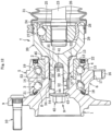
- Each of bearing devices for a wheel according to embodiments illustrated in FIG. 12 to FIG. 27 comprises a seal structure for preventing muddy water or the like from entering the projection and depression fitting structure M for the purpose of rust prevention for the projection and depression fitting structure M.
- the configuration other than the seal structure in the embodiments is the same as that of the above-mentioned embodiments illustrated in FIG. 1 to FIGS. 11 . Therefore, the same reference symbols as those in FIG. 1 to FIGS. 11 are provided so as to omit the overlapping description thereof.
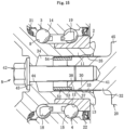
- a structure comprising a seal 52 having a cylindrical shape interposed between the stem section 30 of the outer joint member 20 and the protruding wall portion 43 of the hub wheel 1.
- the seal 52 is preferably an elastic member made of rubber or a resin.
- An inboard-side end portion 53 of the seal 52 is fitted into an axial end small-diameter portion that is the accommodating portion 40 formed in the stem section 30 so as to be fixed thereto (see FIG. 14 and FIG. 15 ) .
- a structure comprising a seal 55 having a cylindrical shape interposed between the protruding wall portion 43 of the hub wheel 1 and the bolt 42.
- the seal 55 is preferably an elastic member made of rubber or a resin.
- An inner peripheral surface of the seal 55 is brought into close contact with the shank-portion base part 50 of the bolt 42 with a predetermined interference by fixing an outer peripheral surface of the seal 55 to an inner diameter of the through hole of the protruding wall portion 43 of the hub wheel 1 with an adhesive or the like, or the outer peripheral surface is brought into close contact with the inner diameter of the through hole of the protruding wall portion 43 of the hub wheel 1 with a predetermined interference by fixing the inner peripheral surface to the shank-portion base part 50 of the bolt 42 with the adhesive or the like.
- a structure comprising a seal 56 having a cylindrical shape and provided with a flange portion 57 formed on the outboard-side end portion thereof to project radially outward, which is interposed between the protruding wall portion 43 of the hub wheel 1 and the bolt 42.
- the seal 56 is preferably an elastic member made of rubber or a resin.
- a structure of mounting the seal 56 and sealing functions are the same as those of the seal 55 described above in the embodiment illustrated in FIG. 16 and FIG. 17 , and hence the overlapping description thereof is herein omitted.
- the flange portion 57 is provided to the outboard-side end portion.
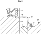
- a structure comprising a seal 60 with a lip, which comprises a lip member 59 mounted to an inner diameter of a distal end portion of a seal member 58 made of a metal, and is interposed between the outer joint member 20 and the inner ring 2.
- the lip member 59 is preferably an elastic member made of rubber or a resin.
- the seal 60 is fixed by fitting a base end portion of the seal member 58 into an end portion of the inner ring 2. Then, the lip member 59 mounted to the inner diameter of the distal end portion of the seal member 58 is brought into close contact with the outer peripheral surface of the shoulder portion 45 of the outer joint member 20 by elastic-pressure contact.
- the muddy water or the like is inhibited from entering the projection and depression fitting structure M from a portion between the crimped portion 13 of the hub wheel 1 and the shoulder portion 45 of the outer joint member 20 by the seal 60 interposed between the shoulder portion 45 of the outer joint member 20 and the inner ring 2.
- a structure comprising a labyrinth seal 61 made of a metal interposed between the outer joint member 20 and the inner ring 2.
- the seal 61 is fixed by fitting a cylindrical base end portion 62 thereof into the end portion of the inner ring 2 so that a curved distal end portion 63 thereof is located close to the outer peripheral surface of the shoulder portion 45 of the outer joint member 20.
- the muddy water or the like is inhibited from entering the projection and depression fitting structure M from the portion between the crimped portion 13 of the hub wheel 1 and the shoulder portion 45 of the outer joint member 20 by the labyrinth structure at the curved distal end portion 63 of the seal 61 interposed between the shoulder portion 45 of the outer joint member 20 and the inner ring 2.
- a structure comprising a seal 66 with a lip, which comprises a lip member 65 made of rubber or a resin mounted to a distal end portion of a seal member 64 made of a metal, and is interposed between the outer joint member 20 and the inner ring 2.
- the lip member 65 is preferably an elastic member made of rubber or a resin.
- the seal 66 is fixed by fitting a base end portion of the seal member 64 over the shoulder portion 45 of the outer joint member 20 so that the lip member 65 mounted to the distal end portion of the seal member 64 is brought into close contact with the end surface of the inner ring 2 by elastic-pressure contact.
- the muddy water or the like is inhibited from entering the projection and depression fitting structure M from the portion between the crimped portion 13 of the hub wheel 1 and the shoulder portion 45 of the outer joint member 20 by the seal 66 interposed between the shoulder portion 45 of the outer joint member 20 and the inner ring 2.
- a structure comprising a labyrinth seal 67 made of a metal interposed between the outer joint member 20 and the inner ring 2.
- the seal 67 is fixed by fitting a cylindrical base end portion 68 thereof over the shoulder portion 45 of the outer joint member 20 so that a bent distal end portion 69 thereof is located close to the end surface of the inner ring 2.
- the muddy water or the like is inhibited from entering the projection and depression fitting structure M from the portion between the crimped portion 13 of the hub wheel 1 and the shoulder portion 45 of the outer joint member 20 by the labyrinth structure at the bent distal end portion 69 of the seal 67 interposed between the shoulder portion 45 of the outer joint member 20 and the inner ring 2.
- the screw fastening structure N in which the bolt 42 is fastened in a state of being locked to the protruding wall portion 43 of the hub wheel 1 by threadedly engaging the bolt 42 with the female thread portion 41 of the stem section 30, has been exemplarily described.
- another screw fastening structure may also be configured to comprise a male thread portion formed at the axial end of the stem section 30 of the outer joint member 20 and a nut that is a female thread portion to be locked to the protruding wall portion 43 of the hub wheel 1 in a state of being threadedly engaged with the male thread portion.
- the crimping structure in which an end portion of the small-diameter step portion 11 of the hub wheel 1 is crimped outward by orbital forming to retain the inner ring 2 by the crimped portion 13 to be integrated with the hub wheel 1 so that the constant velocity universal joint 7 is separable from the wheel bearing 6, has been exemplarily described.
- a non-crimping structure in which the inner ring 2 is press-fitted into the small-diameter step portion 11 of the hub wheel 1 so that the end portion of the inner ring 2 is brought into abutment against the shoulder portion 45 of the outer joint member 20, may also be used.
- the application to the bearing device for a wheel of a type in which one of the double-row inner raceway surfaces 8 and 12 formed on the inner member comprising the hub wheel 1 and the inner ring 2, that is, the inner raceway surface 8 on the outboard side, is formed on the outer periphery of the hub wheel 1 (referred to as "third generation"), has been exemplarily described.
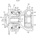
- the configuration in which the hub wheel and the constant velocity universal joint are fastened by the bolt is capable of assembling and disassembling and therefore is excellent in maintainability. If the fastened bolt is loosened after the incorporation into the vehicle, however, there is a fear of inconvenience such as generation of a backlash to generate abnormal noise or acceleration of wear.
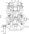
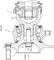
- FIG. 28 is a longitudinal sectional view of a bearing device for a wheel, to which a first embodiment of a bolt loosening prevention structure is applied
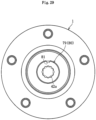
- FIG. 29 is a front view of the bearing device for a wheel illustrated in FIG. 28 as viewed in a direction indicated by the arrow Y
- FIG. 30 is a longitudinal sectional view for illustrating a principal part of FIG. 28 in an enlarged manner
- FIG. 31 is a front view for illustrating a principal part of FIG. 29 in an enlarged manner.
- a configuration of the bearing device for a wheel illustrated in FIG. 28 is basically the same as that of the bearing device for a wheel illustrated in FIG. 3 , and therefore the overlapping description thereof is omitted.
- a cap member 80 as a loosening prevention member 79 is mounted onto a head portion 42a of the bolt 42 for fastening the hub wheel 1 and the constant velocity universal joint 7. Through an intermediation of the cap member 80, rotation of the bolt 42 in a loosening direction is regulated between the head portion 42a of the bolt 42 and the hub wheel 1.
- the cap member 80 comprises a cap main body 82 having a cylindrical shape and a closed end, which is mounted to the head portion 42a of the bolt 42, and a flange portion 83 having a flat-plate annular shape provided to an opening edge portion of the cap main body 82.
- a plurality of depressed portions 82b are formed so as to be arranged equiangularly (see FIG. 31 ) .
- the number of provided depressed portions 82b is twice (twelve in total) as many as the number (six in FIG. 31 ) of the angular portions 42c provided to the head portion 42a.
- the number of portions at which the cap member 80 can be positionally aligned with the head portion 42a becomes twice as many as that compared to the case where the number of depressed portions 82b is the same as that of the angular portions 42c. Therefore, fitting work is facilitated.
- the number of depressed portions 82b may be three times as many as the number of angular portions 42c or larger, or the number of depressed portions 82b may be the same as the number of angular portions 42c.
- an inner diameter of the side wall portion 82a of the cap main body 82 is set slightly smaller than an outer diameter of a corresponding portion of the head portion 42a. Specifically, the cap member 80 is fitted by press-fitting over the head portion 42a. Therefore, the cap member 80 hardly comes off in the axial direction.
- An engagement portion 81 that is engageable with the cap member 80 is provided to the hub wheel 1 on a side where the cap member 80 is provided.
- the engagement portion 81 is a protruding portion 84 partially projecting in the peripheral direction.
- FIG. 32A is a perspective view for illustrating a state before the cap member 80 is engaged with the protruding portion 84 of the hub wheel 1
- FIG. 32B is a perspective view for illustrating a state in which the cap member 80 is engaged with the protruding portion 84 of the hub wheel 1.
- an outer edge portion of the flange portion 83 is arranged so as to cover the protruding portion 84. Then, the flange portion 83 is crimped in the vicinity of the protruding portion 84. By the crimping, the flange portion 83 is deformed in accordance with a shape of the protruding portion 84. The flange portion 83 is engaged with the protruding portion 84 in a deformed portion (crimped portion) Z, thereby holding the cap member 80 in the peripheral direction. As described above, in this embodiment, the bolt 42 is held with respect to the hub wheel 1 through an intermediation of the cap member 80, thereby regulating the rotation of the bolt 42 in the loosening direction so as to prevent loosening.
- protruding portion 84 only one protruding portion 84 is provided.
- a plurality of the protruding portions 84 may be provided in the peripheral direction so that the flange portion 83 is crimped to each of the protruding portions 84 or an arbitrarily selected one of the protruding portions 84.
- FIG. 33 is a longitudinal sectional view of a second embodiment of the bolt loosening prevention structure, and FIG. 34 is a front view thereof.
- a shape of the engagement portion 81 provided to the hub wheel 1 differs from that in the first embodiment described above.
- the engagement portion 81 is a recessed portion 85 that is partially recessed in the peripheral direction.
- the remaining configuration is the same as that in the first embodiment.
- the outer edge portion of the flange portion 83 is arranged so as to cover the recessed portion 85. Then, the flange portion 83 is crimped at a position of the recessed portion 85. By the crimping, the flange portion 83 is deformed in accordance with a shape of the recessed portion 85. The flange portion 83 is engaged with the recessed portion 85 in the deformed portion (crimped portion) Z, thereby holding the cap member 80 in the peripheral direction. As a result, the rotation of the bolt 42 in the loosening direction is regulated to prevent loosening.
- a plurality of the recessed portions 85 may be provided over the peripheral direction so that the flange portion 83 is crimped to each of the recessed portions 85 or an arbitrarily selected one of the recessed portions 85.
- FIG. 36 is a longitudinal sectional view of a third embodiment of the bolt loosening prevention structure
- FIG. 37 is a front view thereof. Further, FIG. 36 is a sectional view taken along the line G-G in FIG. 37 .
- the loosening prevention member 79 is a clip member 86 in the third embodiment.
- the clip member 86 comprises a clip main body 86a having an opening portion 86c in a part in the peripheral direction, which is to be mounted to the head portion 42a of the bolt 42, and a plurality of projecting portions 87, each projecting in a radially outward direction over the peripheral direction of the clip main body 86a (see FIG. 37 ).
- an insertion hole 86e into which the head portion 42a of the bolt 42 is inserted, is formed.
- the insertion hole 86e is formed to have a hexagonal shape that is the same as the shape of the head portion 42a of the bolt 42.
- the recessed portions 85 are provided as the engagement portion 81 to which the projecting portions 87 of the clip member 86 are engageable.
- a plurality of the recessed portions 85 are provided in the peripheral direction.
- both end portions of the clip main body 86a are gripped by the pliers or the like. Then, the clip main body 86a is elastically deformed so that the opening portion 86c is enlarged and the head portion 42a of the bolt 42 is inserted into the insertion hole 86e of the clip main body 86a in this state. Then, by an elastic restoring force of the clip member 86, the clip main body 86a is locked to the side surface of the head portion 42a.
- one of the plurality of projecting portions 87 of the clip member 86 is positionally aligned with an arbitrarily selected one of the recessed portions 85 and is then inserted into the corresponding recessed portion 85.
- the projecting portion 87 is brought into a state of being engageable with the recessed portion 85 in the peripheral direction. Therefore, the bolt 42 can be held in the peripheral direction with respect to the hub wheel 1 through an intermediation of the clip member 86.
- the rotation of the bolt 42 in the loosening direction is regulated.
- FIG. 38 is a longitudinal sectional view of a fourth embodiment of the bolt loosening prevention structure, and FIG. 39 is a front view thereof. Further, FIG. 38 is a sectional view taken along the line H-H in FIG. 39 .
- a plurality of the projecting portions 87 similar to those provided to the clip member 86 are provided to the flange portion 83 of the cap member 80 as the loosening prevention member 79 over the peripheral direction.
- a plurality of the recessed portions 85 similar to those described above are provided to the hub wheel 1 over the peripheral direction.
- one of the plurality of projecting portions 87 is positionally aligned with an arbitrarily selected one of the recessed portions 85 and is then inserted into the corresponding recessed portion 85 in the same manner as described above.
- the projecting portion 87 is brought into a state of being engageable with the recessed portion 85 in the peripheral direction, thereby holding the bolt 42 to the hub wheel 1 through an intermediation of the cap member 80 in the peripheral direction.
- the rotation of the bolt 42 in the loosening direction is regulated.
- FIG. 40 is a longitudinal sectional view of a fifth embodiment of the bolt loosening prevention structure, and FIG. 41 is a front view thereof. Further, FIG. 40 is a sectional view taken along the line I-I in FIG. 41 .
- the protruding portion 84 is provided as the engagement portion 81 on the hub wheel 1, whereas a depressed portion 88 that is engageable with the protruding portion 84 is provided to the clip member 86.
- a plurality of protruding portions 84 and a plurality of depressed portions 88 may be provided side by side over the peripheral direction.
- the clip main body 86a is elastically deformed to mount the clip member 86 over the head portion 42a of the bolt 42 as in the case described above.
- the depressed portion 88 of the clip member 86 is positionally aligned with the protruding portion 84 of the hub wheel 1.
- the depressed portion 88 is brought into a state of being engageable with the protruding portion 84 in the peripheral direction. In this manner, the rotation of the bolt 42 in the loosening direction is regulated through an intermediation of the clip member 86.
- FIG. 42 is a longitudinal sectional view of a sixth embodiment of the bolt loosening prevention structure
- FIG. 43 is a front view thereof. Further, FIG. 42 is a sectional view taken along the line J-J in FIG. 43 .
- the depressed portion 88 that is engageable with the protruding portion 84 of the hub wheel 1 is provided to the flange portion 83 of the cap member 80. Note that, a plurality of the protruding portions 84 and a plurality of the depressed portions 88 may be provided side by side over the peripheral direction.
- the depressed portion 88 of the cap member 80 is positionally aligned with the protruding portion 84 of the hub wheel 1. In this manner, the depressed portion 88 is brought into a state of being engageable with the protruding portion 84 in the peripheral direction. In this manner, the rotation of the bolt 42 in the loosening direction is regulated through an intermediation of the cap member 80.
- FIG. 44A and FIG. 44B are longitudinal sectional views of a seventh embodiment of the bolt loosening prevention structure. Further, FIG. 44A is an illustration of a state before the cap member 80 is completely press-fitted over the head portion 42a of the bolt 42, and FIG. 44B is an illustration of a state in which the cap member 80 is completely press-fitted over the head portion 42a of the bolt 42.
- the side wall portion 82a of the cap main body 82 is formed into a tapered shape so that an inner diameter becomes larger as approaching to its opening side.
- the cap member 80 becomes easy to be press-fitted over the head portion 42a of the bolt 42.
- the cap member 80 including the projecting portion 87 is formed to have the tapered shape in this embodiment, the cap member 80 may be similarly formed to have the tapered shape also for the cap member 80 having another configuration.
- FIG. 45 is a longitudinal sectional view of an eighth embodiment of the bolt loosening prevention structure, and FIG. 46 is a front view thereof.
- the bolt 42 is configured to be prevented from being loosened by using the loosening prevention member 79 (cap member 80 or clip member 86) in each of the embodiments described above, the loosening prevention member 79 as described above is not used in the eighth embodiment illustrated in FIG. 45 .
- a flange portion 42d having a small thickness is provided to the head portion 42a of the bolt 42. The flange portion 42d is directly engaged with the protruding portion 84 as the engagement portion 81 provided to the hub wheel 1.
- the bolt 42 is screwed into the female thread portion 41 (see FIG. 1 ) of the constant velocity universal joint 7.
- the flange portion 42d of the bolt 42 is crimped in the vicinity of the protruding portion 84.
- the flange portion 42d is deformed in accordance with the shape of the protruding portion 84.
- the flange portion 42d is engaged with the protruding portion 84 in the deformed portion (crimped portion) Z.
- the bolt 42 is held to the hub wheel 1 in the peripheral direction.
- the flange portion 42d of the bolt 42 is crimped.
- the rotation of the bolt 42 in the loosening direction can be regulated between the head portion 42a of the bolt 42 and the hub wheel 1.
- the flange portion 42d is preferred not to be subjected to thermosetting treatment so as to facilitate the crimping.
- a plurality of the protruding portions 84 may be provided in the peripheral direction so that the flange portion 42d is crimped to each of the protruding portions 84 or an arbitrarily selected one of the protruding portions 84.
- FIG. 47 is a longitudinal sectional view of a ninth embodiment of the bolt loosening prevention structure, and FIG. 48 is a front view thereof.
- the flange portion 42d having a small thickness in the same manner as described above is provided to the head portion 42a of the bolt 42.
- the flange portion 42d is directly engaged with the recessed portion 85 as the engagement portion 81 provided to the hub wheel 1.
- the bolt 42 is screwed into the female thread portion 41 (see FIG. 1 ) of the constant velocity universal joint 7.
- the flange portion 42d of the bolt 42 is crimped at the position of the recessed portion 85.
- the flange portion 42d is deformed in accordance with the shape of the recessed portion 85.
- the flange portion 42d is engaged with the recessed portion 85 in the deformed portion (crimped portion) Z.
- the bolt 42 is held to the hub wheel 1 in the peripheral direction.
- the flange portion 42d is preferred not to be subjected to thermosetting treatment so as to facilitate the crimping.
- a plurality of the recessed portions 85 may be provided over the peripheral direction so that the flange portion 42d is crimped to each of the recessed portions 85 or an arbitrarily selected one of the recessed portions 85.
- FIG. 49 is a longitudinal sectional view of a tenth embodiment of the bolt loosening prevention structure
- FIG. 50 is a front view thereof.
- the head portion 42a of the bolt 42 is welded to the hub wheel 1 to be fixed thereto (in welding portions W), thereby regulating the rotation of the bolt 42 in the loosening direction between the head portion 42a of the bolt 42 and the hub wheel 1.
- the head portion 42a of the bolt 42 is spot-welded to a radial end surface 43a of the protruding wall portion 43 of the hub wheel 1, against which the head portion 42a abuts, at a plurality of positions over the peripheral direction.
- welding means known means such as laser welding or electron-beam welding can be used.
- FIG. 51A and FIG. 51B are longitudinal sectional views of an eleventh embodiment of the bolt loosening prevention structure.
- FIG. 51A is a view for illustrating a state before the crimping of the loosening prevention member
- FIG. 51B is a view for illustrating a state after the crimping of the loosening prevention member.
- FIG. 52A and FIG. 52B are front views of FIG. 51A and FIG. 51B , respectively.
- a pin-like member 89 is used as the loosening prevention member 79.
- the pin-like member 89 comprises a shaft-like insertion portion 91 that is insertable into an insertion hole 90 provided in the hub wheel 1, and a deformable portion 92 formed integrally therewith. Further, the insertion hole 90 is formed on a radial surface of the hub wheel 1, against which the head portion 42a of the bolt 42 abuts.
- the deformable portion 92 has a ball-like shape.
- a distal end of the insertion portion 91 of the pin-like member 89 is first inserted into the insertion hole 90 in a state in which the bolt 42 is fastened to the hub wheel 1.
- the deformable portion 92 having the ball-like shape, which is exposed from the insertion hole 90 is crimped by hitting or the like to be deformed into a flat shape.
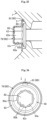
- the deformable portion 92 may be brought into close contact with a plane portion 42e of the head portion 42a as illustrated in FIG. 53 .
- the pin-like member 89 is preferred not to be subjected to thermosetting treatment (to be left as mild steel) so as to facilitate the crimping.
- the pin-like member 89 is formed to have a straight bar-like shape.
- a portion, with which the pin-like member 89 is brought into close contact may be the angular portion 42c formed on the side surface of the head portion 42a as illustrated in FIG. 55B , or may be the plane portion 42e formed on the side surface of the head portion 42a as illustrated in FIG. 56 .
- FIG. 57A and FIG. 57B are longitudinal sectional views of a twelfth embodiment of the bolt loosening prevention structure.
- FIG. 57A is a view for illustrating a state before the crimping of the loosening prevention member
- FIG. 57B is a view for illustrating a state after the crimping of the loosening prevention member.
- FIG. 58A and FIG. 58B are front views of FIG. 57A and FIG. 57B , respectively.
- a washer 93 is interposed between the hub wheel 1 and the head portion 42a of the bolt 42.
- the above-mentioned insertion hole 90 is formed through the washer 93.
- the twelfth embodiment is basically the same as the embodiments illustrated in FIG. 51A, FIG. 51B , FIG. 52A, FIG. 52B , and FIG. 53 .
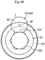
- a portion of the bolt 42, with which the pin-like member 89 is brought into close contact may be the angular portion 42c formed on the side surface of the head portion 42a (see FIG. 58B ), or may be the plane portion 42e formed on the side surface of the head portion 42a (see FIG. 59 ). Further, it is desirable to use a washer having both surfaces that are subjected to knurling or a spring washer as the washer 93 so that the rotation in the peripheral direction hardly occurs.
- the pin-like member 89 formed to have the straight bar-like shape may be inserted into the insertion hole 90 formed through the washer 93.
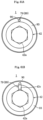
- the portion exposed from the insertion hole 90 is crimped in a bent manner to be deformed in a state in which the pin-like member 89 is inserted into the insertion hole 90.
- an end portion of the pin-like member 89 is brought into close contact with the head portion 42a of the bolt 42 to be engaged with each other.
- the rotation of the bolt 42 in the loosening direction can be regulated.
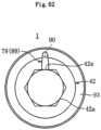
- a portion of the bolt 42, with which the pin-like member 89 is brought into close contact may be the angular portion 42c formed on the side surface of the head portion 42a (see FIG. 61B ), or may be the plane portion 42e formed on the side surface of the head portion 42a (see FIG. 62 ).
- each of the embodiments of the bolt loosening prevention structure has been described above.
- the rotation of the bolt in the loosening direction with respect to the hub wheel can be regulated between the head portion of the bolt and the hub wheel.
- the fastened state of the hub wheel and the constant velocity universal joint can be maintained over a long period of time.
- inconvenience such as the generation of abnormal noise or the acceleration of wear due to the loosening of the fastened bolt can be suppressed.
- the bolt loosening is prevented by the head portion of the bolt, which is exposed from the hub wheel. Therefore, whether or not the loosening is prevented after the bolt is fastened can be easily confirmed visually from the outside.
- the application of the bolt loosening prevention structure according to each of the embodiments described above is not limited to the above-mentioned bearing device for a wheel.
- the above-mentioned bolt loosening prevention structure is also applicable to bearing devices for a wheel illustrated in FIG. 63 , FIG. 64 , and FIG. 65 .
- the bearing device for a wheel illustrated in FIG. 63 comprises a wheel bearing 220 comprising an inner member 200, an outer member 205, and double-row balls 203 and 204 interposed therebetween, and a fixed type constant velocity universal joint 206 fastened thereto by a bolt 250, as main components thereof.
- the inner member 200 comprises a hub wheel 201 having a wheel mounting flange 209 for allowing a wheel (not shown) to be mounted thereto and an inner ring 202 mounted on an outer peripheral surface of the hub wheel 201.
- inner raceway surfaces 207 and 208 are respectively formed.
- the outer member 205 has an inner peripheral surface on which double-row outer raceway surfaces 213 and 214 respectively opposed to the inner raceway surfaces 207 and 208 of the hub wheel 201 and the inner ring 202 are formed.
- the double-row balls 203 and 204 are interposed between the outer raceway surfaces 213 and 214 and the inner raceway surfaces 207 and 208, which are opposed to each other.
- the constant velocity universal joint 206 comprises an outer joint member 224 having track grooves 223 formed in an inner peripheral surface thereof, an inner joint member 226 having track grooves 225 formed in an outer peripheral surface thereof so as to be opposed to the track grooves 223 of the outer joint member 224, balls 227 built into spaces between the track grooves 223 and 225, a cage 228 interposed between the inner peripheral surface of the outer joint member 224 and the outer peripheral surface of the inner joint member 226 to retain the balls 227, and the like.
- the outer joint member 224 comprises a mouth section 229 that accommodates internal components such as the inner joint member 226, the balls 227, and the cage 228, and a stem section 230 that integrally extends from the mouth section 229 in an axial direction. Further, a male spline 237 including a plurality of projecting portions extending in the axial direction is formed on an outer peripheral surface of the stem section 230.
- a female spline 239 to be fitted to the male spine 237 of the stem section 230 is formed on an inner peripheral surface of a hole portion 238 of the hub wheel 201.
- a screw hole 240 is formed in the stem section 230.
- a bolt 250 is inserted into the screw hole 240 so that the bolt 250 is threadedly engaged with a female thread portion 241 formed on the screw hole 240, and a head portion 250a of the bolt 250 is brought into abutment against a radial end surface 210 of the hub wheel 201, thereby fastening the constant velocity universal joint 206 to the hub wheel 201.
- a bearing device for a wheel illustrated in FIG. 64 comprises the wheel bearing 220 comprising the inner member 200, the outer member 205, and the double-row balls 203 and 204 interposed between the inner member 200 and the outer member 205, and the fixed type constant velocity universal joint 206 fastened thereto by the bolt 250, as main components thereof.
- an axial-alignment protruding portion 231 having a disc-like shape is provided integrally with the mouth section 229 of the constant velocity universal joint 206.
- the hub wheel 201 and the constant velocity universal joint 206 are coupled to each other while being axially aligned.
- face splines 242 and 243 are formed on surfaces of the mouth section 229 of the outer joint member 224 and the hub wheel 201, which are opposed to each other, and are engaged with each other.
- Each of the face splines 242 and 243 comprises a plurality of projecting portions and depressed portions extending in the radial direction, which are formed alternately along the peripheral direction.
- the screw hole 240 into which the bolt 250 is to be inserted, is formed in the outer joint member 224 of the constant velocity universal joint 206.
- the bolt 250 is threadedly engaged with the female thread portion 241 formed on the screw hole 240, and the head portion 250a of the bolt 250 is brought into abutment against the radial end surface 210 of the hub wheel 201, thereby fastening the constant velocity universal joint 206 to the hub wheel 201.
- a bearing device for a wheel illustrated in FIG. 65 In contrast to the bearing device for a wheel illustrated in FIG. 63 , the suppression of a backlash between the engaged splines in the peripheral direction and the improvement of workability in coupling the hub wheel and the constant velocity universal joint are achieved in a bearing device for a wheel illustrated in FIG. 65 .
- a projecting portion male spline 237 or female spline 239 is formed only on one of portions of an outer peripheral surface of the stem section 230 of the outer joint member 224 and the hole portion 238 of the hub wheel 201.
- the one portion is press-fitted into another portion in the axial direction to form a depressed portion to be fitted over the projecting portion and to be brought into close contact therewith on the another portion.
- the remaining configuration is basically the same as that of the bearing device for a wheel illustrated in FIG. 63 . Also in this case, the bolt 250 is inserted into the screw hole 240 of the stem section 230 to be fastened thereto, thereby fastening the constant velocity universal joint 206 to the hub wheel 201.
- the fastened state of the hub wheel and the constant velocity universal joint can be maintained over a long period of time with the application of the bolt loosening prevention structure according to each of the embodiments described above.
- inconvenience such as the generation of abnormal noise and the acceleration of wear due to the loosening of the fastened bolt can be suppressed.
Landscapes
- Engineering & Computer Science (AREA)
- Mechanical Engineering (AREA)
- General Engineering & Computer Science (AREA)
- Rolling Contact Bearings (AREA)
Claims (11)
- Verfahren zur Montage einer Lagervorrichtung für ein Rad, wobei die Lagervorrichtung ein Radlager (6), ein universales Gleichlaufgelenk (7) und eine Schraubbefestigungsstruktur (N) umfasst, wobei das Radlager (6) umfasst:ein Außenelement (5), das zweireihige äußere Laufflächen (14, 15) aufweist, die an einem Innenumfang davon ausgebildet sind;ein Innenelement (1, 2), das ein Nabenrad (1) und einen Innenring (2) umfasst und zweireihige innere Laufflächen (8, 12) aufweist, die an einem Außenumfang davon ausgebildet sind, die den zweireihigen äußeren Laufflächen (14, 15) gegenüberliegen; undzweireihige Kugeln (3, 4), die zwischen den zweireihigen äußeren Laufflächen (14, 15) des Außenelements (5) und den zweireihigen inneren Laufflächen (8, 12) des Innenelements (1, 2) eingefügt sind,wobei das universale Gleichlaufgelenk (7) durch die Schraubbefestigungsstruktur (N) an das Radlager (6) gekoppelt ist, indem ein Schaftabschnitt (30) eines äußeren Gelenkelements (20) des universalen Gleichlaufgelenks (7) in einen Innendurchmesser des Nabenrads (1) gepasst wird, so dass ein Schulterabschnitt (45) des äußeren Gelenkselements (20) in Anlage gegen einen Endabschnitt des Innenelements (1, 2) gebracht wird, wobeider Schaftabschnitt (30) des äußeren Gelenkselements (20) eine Vielzahl vorstehender Abschnitte (33) aufweist, die sich in einer axialen Richtung erstrecken, unddie innere Umfangsfläche des Nabenrads (1) eine Vielzahl vertiefter Abschnitte (36) aufweist, die eine Überlagerung "n" mit den vorstehenden Abschnitten (33) aufweisen, und ein Führungsabschnitt zur Führung des Beginns der Presspassung ist auf der innenliegenden Seite der vertieften Abschnitte (36) bereitgestellt, die in dem Schaftloch (34) des Nabenrads (1) im Vorhinein ausgebildet sind; wobei der Führungsabschnitt eine Vielzahl vertiefter Abschnitte (38) umfasst, die vergleichsweise größer als die vorstehenden Abschnitte (33) des Schaftabschnitts (30) ausgebildet sind;wobei die Vielzahl der vertieften Abschnitte (38), die als die Führungsabschnitte fungieren, einen Spalt (m) zwischen einem radial distalen Endabschnitt (72) und einem Umfangsseitenwandabschnitt (71) der Vielzahl der vorstehenden Abschnitte (33) aufweisen;die Vielzahl der vertieften Abschnitte (36) die Überlagerung (n) nur bezüglich des Umfangsseitenwandabschnitts (71) von jedem der vorstehenden Abschnitte (33) aufweisen;jeder der vertieften Abschnitte (36) einen Spalt (p) bezüglich des radial distalen Endabschnitt (72) von jedem der vorstehenden Abschnitte (33) aufweist;ein Wert, der durch Teilen einer axialen Länge (L1) ab dem Schulterabschnitt (45) des äußeren Gelenkselements (20), gegen das der Endabschnitt des Innenelements (1, 2) anliegt, bis zu der Vielzahl der vorstehenden Abschnitte (33) durch einen maximalen Außendurchmesser (D) des Schaftabschnitts (30) erhalten wird, auf 0,3 oder kleiner festgelegt ist; undein Wert, der durch Teilen einer axialen Länge (L2) des Schaftabschnitts (30) durch den maximalen Außendurchmesser (D) des Schaftabschnitts (30) erhalten wird, auf 1,3 oder kleiner festgelegt istwobei das Verfahren umfasstwenn der Schaftabschnitt (30) zuerst in das Nabenrad (1) pressgepasst wird, werden die Vielzahl der vorstehenden Abschnitte (33) zu der Vielzahl der vertieften Abschnitte (36), die die Überlagerung (n) aufweisen, durch die Vielzahl der vertieften Abschnitte (38), die als die Führungsabschnitte fungieren, geführt, wobei die Vielzahl der vorstehenden Abschnitte (33) in das Nabenrad (1) unter Verwendung einer Axialkraft durch die Schraubbefestigungsstruktur (N) pressgepasst werden, um die Überlagerung (n) durch die vorstehenden Abschnitte (33) zu schneiden, und eine Form der Vielzahl der vorstehenden Abschnitte (33) auf das Nabenrad (1) übertragen wird, um dadurch eine Vorsprungs- und Vertiefungspassstruktur (M) bereitzustellen, in der die Vielzahl der vorstehenden Abschnitte (33) und die Vielzahl der vertieften Abschnitte (36) in engen Kontakt miteinander an einem gesamten Passkontaktabschnitt (X) dazwischen gebracht werden;wobei eine Differenz zwischen einer von der Schraubbefestigung erzeugten Axialkraft und einer durch eine Presspassungskraft erzeugte Axialkraft auf 32 kN oder kleiner festgesetzt ist.
- Das Verfahren nach Anspruch 1, wobei die Schraubbefestigungsstruktur (N) umfasst:einen Innengewindeabschnitt (41), der an einem axialen Ende des Schaftabschnitts (30) des äußeren Gelenkselements (20) ausgebildet ist; undeinen Außengewindeabschnitt (42), der an das Nabenrad (1) in einem Zustand arretiert wird, in welchem er mit dem Innengewindeabschnitt (41) verschraubt ist.
- Das Verfahren nach Anspruch 1 oder 2, wobei:das Nabenrad (1) und das äußere Gelenkselement (20) des universalen Gleichlaufgelenks (7) durch Vermittlung einer Schraube (42) befestigt sind; unddie Drehung der Schraube (42) in einer Lockerungsrichtung zwischen einem Kopfabschnitt (42a) der Schraube (42) und dem Nabenrad (1) reguliert wird.
- Das Verfahren nach Anspruch 3, wobei:das Nabenrad (1) einen Eingriffsabschnitt (81) umfasst; undder Kopfabschnitt (42a) der Schraube (42) ein Lockerungsverhinderungselement (79) aufweist, das mit dem daran montierten Eingriffsabschnitt (81) in Eingriff gebracht werden kann.
- Das Verfahren nach Anspruch 4, wobei:der Eingriffsabschnitt (81) einen vorstehenden Abschnitt (84) oder einen vertieften Abschnitt (85) umfasst; unddas Lockerungsverhinderungselement (79) so konfiguriert ist, dass es mit dem Eingriffsabschnitt (81) in Eingriff gebracht werden kann, indem es an einer Position des Eingriffsabschnitts (81) oder in einer Umgebung davon gekrimpt wird.
- Das Verfahren nach Anspruch 4, wobei:der Eingriffsabschnitt (81) einen vorstehenden Abschnitt (84) oder einen vertieften Abschnitt (85) umfasst; unddas Lockerungsverhinderungselement (79) einen vorstehenden Abschnitt (87) oder einen vertieften Abschnitt (88) umfasst, der mit dem Eingriffsabschnitt (81) eingreifen kann.
- Das Verfahren nach einem der Ansprüche 4 bis 6, wobei das Lockerungsverhinderungselement (79) ein Kappenelement (80) umfasst, das auf den Kopfabschnitt (42a) der Schraube (42) durch Presspassung montiert werden kann.
- Das Verfahren nach einem der Ansprüche 4 bis 6, wobei das Lockerungsverhinderungselement (79) ein Clipelement (86) umfasst, das einen Öffnungsabschnitt (86c) in einem Teil in einer Umfangsrichtung aufweist, wobei das Clipelement (86) auf den Kopfabschnitt (42a) der Schraube (42) durch elastische Verformung des Öffnungsabschnitts (86c) in einer vergrößerten Weise montiert werden kann.
- Das Verfahren nach Anspruch 3, wobei:das Nabenrad (1) einen Eingriffsabschnitt (81) umfasst; undder Kopfabschnitt (42a) der Schraube (42) einen Flanschabschnitt (83) umfasst, der mit dem Eingriffsabschnitt (81) eingreifen kann.
- Das Verfahren nach Anspruch 9, wobei:der Eingriffsabschnitt (81) einen vorstehenden Abschnitt (84) oder einen vertieften Abschnitt (85) umfasst; undder Flanschabschnitt (83) so konfiguriert ist, dass er mit dem Eingriffsabschnitt (81) in Eingriff gebracht werden kann, indem er an einer Position des Eingriffsabschnitts (81) oder in einer Umgebung davon gekrimpt wird.
- Das Verfahren nach Anspruch 3, wobei der Kopfabschnitt (42a) der Schraube (42) durch Schweißen an dem Nabenrad (1) befestigt wird.
Applications Claiming Priority (5)
| Application Number | Priority Date | Filing Date | Title |
|---|---|---|---|
| JP2013049196 | 2013-03-12 | ||
| JP2013058233 | 2013-03-21 | ||
| JP2013114139A JP6207882B2 (ja) | 2013-03-21 | 2013-05-30 | 車輪用軸受装置 |
| JP2013147637A JP6253906B2 (ja) | 2013-03-12 | 2013-07-16 | 車輪用軸受装置 |
| PCT/JP2014/053404 WO2014141808A1 (ja) | 2013-03-12 | 2014-02-14 | 車輪用軸受装置 |
Publications (3)
| Publication Number | Publication Date |
|---|---|
| EP2974883A1 EP2974883A1 (de) | 2016-01-20 |
| EP2974883A4 EP2974883A4 (de) | 2016-11-09 |
| EP2974883B1 true EP2974883B1 (de) | 2023-07-12 |
Family
ID=54415288
Family Applications (1)
| Application Number | Title | Priority Date | Filing Date |
|---|---|---|---|
| EP14764201.1A Active EP2974883B1 (de) | 2013-03-12 | 2014-02-14 | Radlagervorrichtung |
Country Status (4)
| Country | Link |
|---|---|
| US (1) | US10086649B2 (de) |
| EP (1) | EP2974883B1 (de) |
| CN (1) | CN105026175B (de) |
| WO (1) | WO2014141808A1 (de) |
Families Citing this family (5)
| Publication number | Priority date | Publication date | Assignee | Title |
|---|---|---|---|---|
| JP6320695B2 (ja) * | 2013-07-16 | 2018-05-09 | Ntn株式会社 | 車輪用軸受装置及びその組立方法 |
| CN108473052B (zh) * | 2015-12-22 | 2022-04-19 | 沃尔沃建筑设备公司 | 轮毂单元 |
| US11879500B2 (en) * | 2021-11-23 | 2024-01-23 | Schaeffler Technologies AG & Co. KG | Clamping configuration for wheel bearing assembly |
| US20240278597A1 (en) * | 2023-02-17 | 2024-08-22 | GM Global Technology Operations LLC | Half shaft to bearing connection to reduce driveline click |
| CN116447302A (zh) * | 2023-05-11 | 2023-07-18 | 中国北方车辆研究所 | 一种防止取力器端面漏油的密封结构 |
Family Cites Families (27)
| Publication number | Priority date | Publication date | Assignee | Title |
|---|---|---|---|---|
| US3875985A (en) * | 1973-04-07 | 1975-04-08 | Koyo Seiko Co | Device for fixing bolts and nuts |
| DE2903706A1 (de) * | 1979-01-31 | 1980-08-14 | Kraftwerk Union Ag | Verdrehsicherung fuer in ein bauteil eingeschraubte kopfschrauben |
| US4906150A (en) * | 1985-07-17 | 1990-03-06 | Bennett Bruce A | Locking fastener |
| JP2827454B2 (ja) | 1990-05-25 | 1998-11-25 | 三菱マテリアル株式会社 | 疎水性アルミナ |
| JPH0431312U (de) * | 1990-07-10 | 1992-03-13 | ||
| US5297693A (en) * | 1992-10-07 | 1994-03-29 | Allied-Signal Inc. | Closure member locking retainer |
| DE19908134A1 (de) * | 1999-02-25 | 2000-08-31 | Abb Alstom Power Ch Ag | Sicherungsvorrichtung für eine Schraube oder eine Schraubenmutter |
| WO2001088391A1 (en) * | 2000-05-19 | 2001-11-22 | Eisuke Ishida | Structure for preventing loosening of threaded fasteners |
| JP4474774B2 (ja) * | 2000-05-31 | 2010-06-09 | 日本精工株式会社 | 車輪駆動用ユニット |
| BR0111302A (pt) * | 2000-09-29 | 2003-04-29 | Nsk Ltd | Unidade de mancal para acionamento de roda |
| JP2002178706A (ja) * | 2000-10-06 | 2002-06-26 | Nsk Ltd | 車輪駆動用軸受ユニット |
| JP2002187403A (ja) | 2000-12-22 | 2002-07-02 | Ntn Corp | 車輪用軸受装置 |
| US20020122711A1 (en) * | 2001-03-02 | 2002-09-05 | Dena Porter | Wheel nut retainer |
| JP2003097588A (ja) | 2001-09-25 | 2003-04-03 | Nsk Ltd | 自動車駆動輪ハブユニット |
| JP2003136908A (ja) | 2001-10-30 | 2003-05-14 | Nsk Ltd | 車輪駆動用軸受ユニット |
| JP2003232320A (ja) | 2002-02-06 | 2003-08-22 | Masafumi Emoto | 締め忘れ防止ボルト |
| GB2412406B (en) * | 2004-03-26 | 2006-02-15 | Parker Hannifin Plc | Locking device |
| JP2005315652A (ja) * | 2004-04-27 | 2005-11-10 | Ntn Corp | 荷重センサ内蔵車輪用軸受装置 |
| US20080289470A1 (en) * | 2006-12-08 | 2008-11-27 | Diamond Products, Limited | Bolt Lock For Saw Blades |
| US7708510B2 (en) * | 2007-11-06 | 2010-05-04 | Reimler James L | Fastener system, fastener system article, and method |
| DE112009000812B4 (de) * | 2008-04-04 | 2024-03-07 | Ntn Corp. | Radlagerungsvorrichtung und Achsenmodul |
| JP2010047059A (ja) * | 2008-08-19 | 2010-03-04 | Ntn Corp | 車輪用軸受装置およびアクスルモジュール |
| ES2345081B1 (es) * | 2008-08-29 | 2011-07-22 | Airbus Operations, S.L. | Dispositivo de brazo separado para aseguramiento de un elemento de union roscada. |
| JP2010144902A (ja) * | 2008-12-22 | 2010-07-01 | Jtekt Corp | スプライン嵌合構造、摺動式トリポード型等速ジョイントおよびボール型等速ジョイント |
| CN102666129B (zh) * | 2009-12-21 | 2015-02-11 | Ntn株式会社 | 车轮用轴承装置 |
| JP2012096749A (ja) * | 2010-11-05 | 2012-05-24 | Jtekt Corp | 車輪用転がり軸受装置 |
| US9447811B2 (en) * | 2011-06-28 | 2016-09-20 | Nicholas Strumbos | Fastener and retainer assembly |
-
2014
- 2014-02-14 CN CN201480011471.0A patent/CN105026175B/zh active Active
- 2014-02-14 US US14/771,555 patent/US10086649B2/en active Active
- 2014-02-14 WO PCT/JP2014/053404 patent/WO2014141808A1/ja not_active Ceased
- 2014-02-14 EP EP14764201.1A patent/EP2974883B1/de active Active
Also Published As
| Publication number | Publication date |
|---|---|
| US10086649B2 (en) | 2018-10-02 |
| US20160016431A1 (en) | 2016-01-21 |
| CN105026175B (zh) | 2019-01-04 |
| CN105026175A (zh) | 2015-11-04 |
| WO2014141808A1 (ja) | 2014-09-18 |
| EP2974883A1 (de) | 2016-01-20 |
| EP2974883A4 (de) | 2016-11-09 |
Similar Documents
| Publication | Publication Date | Title |
|---|---|---|
| EP2759415B1 (de) | Radlager und lagervorrichtung | |
| EP2127902B1 (de) | Tragevorrichtung für ein antriebsrad und montageverfahren dafür | |
| US9829048B2 (en) | Bearing device for wheel | |
| EP3023263B1 (de) | Lagervorrichtung für räder und montageverfahren | |
| EP2974883B1 (de) | Radlagervorrichtung | |
| JP6253909B2 (ja) | 車輪用軸受装置 | |
| JP2018009583A (ja) | 動力伝達軸 | |
| EP3029347B1 (de) | Radlagervorrichtung | |
| JP6042142B2 (ja) | 車輪用軸受、車輪用軸受装置、および車輪用軸受装置の製造方法 | |
| JP6207882B2 (ja) | 車輪用軸受装置 | |
| JP6253906B2 (ja) | 車輪用軸受装置 | |
| JP6239310B2 (ja) | 車輪用軸受装置 | |
| JP2007196936A (ja) | 車輪用軸受装置 | |
| JP6279237B2 (ja) | 車輪用軸受装置 | |
| JP2005219650A (ja) | 駆動車輪用軸受装置 |
Legal Events
| Date | Code | Title | Description |
|---|---|---|---|
| PUAI | Public reference made under article 153(3) epc to a published international application that has entered the european phase |
Free format text: ORIGINAL CODE: 0009012 |
|
| 17P | Request for examination filed |
Effective date: 20151002 |
|
| AK | Designated contracting states |
Kind code of ref document: A1 Designated state(s): AL AT BE BG CH CY CZ DE DK EE ES FI FR GB GR HR HU IE IS IT LI LT LU LV MC MK MT NL NO PL PT RO RS SE SI SK SM TR |
|
| AX | Request for extension of the european patent |
Extension state: BA ME |
|
| DAX | Request for extension of the european patent (deleted) | ||
| A4 | Supplementary search report drawn up and despatched |
Effective date: 20161010 |
|
| RIC1 | Information provided on ipc code assigned before grant |
Ipc: B60B 27/00 20060101ALN20161004BHEP Ipc: F16D 1/076 20060101AFI20161004BHEP |
|
| STAA | Information on the status of an ep patent application or granted ep patent |
Free format text: STATUS: EXAMINATION IS IN PROGRESS |
|
| 17Q | First examination report despatched |
Effective date: 20190409 |
|
| GRAP | Despatch of communication of intention to grant a patent |
Free format text: ORIGINAL CODE: EPIDOSNIGR1 |
|
| STAA | Information on the status of an ep patent application or granted ep patent |
Free format text: STATUS: GRANT OF PATENT IS INTENDED |
|
| INTG | Intention to grant announced |
Effective date: 20230203 |
|
| GRAS | Grant fee paid |
Free format text: ORIGINAL CODE: EPIDOSNIGR3 |
|
| GRAA | (expected) grant |
Free format text: ORIGINAL CODE: 0009210 |
|
| STAA | Information on the status of an ep patent application or granted ep patent |
Free format text: STATUS: THE PATENT HAS BEEN GRANTED |
|
| AK | Designated contracting states |
Kind code of ref document: B1 Designated state(s): AL AT BE BG CH CY CZ DE DK EE ES FI FR GB GR HR HU IE IS IT LI LT LU LV MC MK MT NL NO PL PT RO RS SE SI SK SM TR |
|
| REG | Reference to a national code |
Ref country code: CH Ref legal event code: EP |
|
| REG | Reference to a national code |
Ref country code: DE Ref legal event code: R096 Ref document number: 602014087600 Country of ref document: DE |
|
| REG | Reference to a national code |
Ref country code: IE Ref legal event code: FG4D |
|
| REG | Reference to a national code |
Ref country code: LT Ref legal event code: MG9D |
|
| REG | Reference to a national code |
Ref country code: NL Ref legal event code: MP Effective date: 20230712 |
|
| REG | Reference to a national code |
Ref country code: AT Ref legal event code: MK05 Ref document number: 1587476 Country of ref document: AT Kind code of ref document: T Effective date: 20230712 |
|
| PG25 | Lapsed in a contracting state [announced via postgrant information from national office to epo] |
Ref country code: NL Free format text: LAPSE BECAUSE OF FAILURE TO SUBMIT A TRANSLATION OF THE DESCRIPTION OR TO PAY THE FEE WITHIN THE PRESCRIBED TIME-LIMIT Effective date: 20230712 |
|
| PG25 | Lapsed in a contracting state [announced via postgrant information from national office to epo] |
Ref country code: GR Free format text: LAPSE BECAUSE OF FAILURE TO SUBMIT A TRANSLATION OF THE DESCRIPTION OR TO PAY THE FEE WITHIN THE PRESCRIBED TIME-LIMIT Effective date: 20231013 |
|
| PG25 | Lapsed in a contracting state [announced via postgrant information from national office to epo] |
Ref country code: ES Free format text: LAPSE BECAUSE OF FAILURE TO SUBMIT A TRANSLATION OF THE DESCRIPTION OR TO PAY THE FEE WITHIN THE PRESCRIBED TIME-LIMIT Effective date: 20230712 |
|
| PG25 | Lapsed in a contracting state [announced via postgrant information from national office to epo] |
Ref country code: IS Free format text: LAPSE BECAUSE OF FAILURE TO SUBMIT A TRANSLATION OF THE DESCRIPTION OR TO PAY THE FEE WITHIN THE PRESCRIBED TIME-LIMIT Effective date: 20231112 |
|
| PG25 | Lapsed in a contracting state [announced via postgrant information from national office to epo] |
Ref country code: SE Free format text: LAPSE BECAUSE OF FAILURE TO SUBMIT A TRANSLATION OF THE DESCRIPTION OR TO PAY THE FEE WITHIN THE PRESCRIBED TIME-LIMIT Effective date: 20230712 Ref country code: RS Free format text: LAPSE BECAUSE OF FAILURE TO SUBMIT A TRANSLATION OF THE DESCRIPTION OR TO PAY THE FEE WITHIN THE PRESCRIBED TIME-LIMIT Effective date: 20230712 Ref country code: PT Free format text: LAPSE BECAUSE OF FAILURE TO SUBMIT A TRANSLATION OF THE DESCRIPTION OR TO PAY THE FEE WITHIN THE PRESCRIBED TIME-LIMIT Effective date: 20231113 Ref country code: NO Free format text: LAPSE BECAUSE OF FAILURE TO SUBMIT A TRANSLATION OF THE DESCRIPTION OR TO PAY THE FEE WITHIN THE PRESCRIBED TIME-LIMIT Effective date: 20231012 Ref country code: LV Free format text: LAPSE BECAUSE OF FAILURE TO SUBMIT A TRANSLATION OF THE DESCRIPTION OR TO PAY THE FEE WITHIN THE PRESCRIBED TIME-LIMIT Effective date: 20230712 Ref country code: LT Free format text: LAPSE BECAUSE OF FAILURE TO SUBMIT A TRANSLATION OF THE DESCRIPTION OR TO PAY THE FEE WITHIN THE PRESCRIBED TIME-LIMIT Effective date: 20230712 Ref country code: IS Free format text: LAPSE BECAUSE OF FAILURE TO SUBMIT A TRANSLATION OF THE DESCRIPTION OR TO PAY THE FEE WITHIN THE PRESCRIBED TIME-LIMIT Effective date: 20231112 Ref country code: HR Free format text: LAPSE BECAUSE OF FAILURE TO SUBMIT A TRANSLATION OF THE DESCRIPTION OR TO PAY THE FEE WITHIN THE PRESCRIBED TIME-LIMIT Effective date: 20230712 Ref country code: GR Free format text: LAPSE BECAUSE OF FAILURE TO SUBMIT A TRANSLATION OF THE DESCRIPTION OR TO PAY THE FEE WITHIN THE PRESCRIBED TIME-LIMIT Effective date: 20231013 Ref country code: FI Free format text: LAPSE BECAUSE OF FAILURE TO SUBMIT A TRANSLATION OF THE DESCRIPTION OR TO PAY THE FEE WITHIN THE PRESCRIBED TIME-LIMIT Effective date: 20230712 Ref country code: ES Free format text: LAPSE BECAUSE OF FAILURE TO SUBMIT A TRANSLATION OF THE DESCRIPTION OR TO PAY THE FEE WITHIN THE PRESCRIBED TIME-LIMIT Effective date: 20230712 Ref country code: AT Free format text: LAPSE BECAUSE OF FAILURE TO SUBMIT A TRANSLATION OF THE DESCRIPTION OR TO PAY THE FEE WITHIN THE PRESCRIBED TIME-LIMIT Effective date: 20230712 |
|
| PG25 | Lapsed in a contracting state [announced via postgrant information from national office to epo] |
Ref country code: PL Free format text: LAPSE BECAUSE OF FAILURE TO SUBMIT A TRANSLATION OF THE DESCRIPTION OR TO PAY THE FEE WITHIN THE PRESCRIBED TIME-LIMIT Effective date: 20230712 |
|
| REG | Reference to a national code |
Ref country code: DE Ref legal event code: R097 Ref document number: 602014087600 Country of ref document: DE |
|
| PG25 | Lapsed in a contracting state [announced via postgrant information from national office to epo] |
Ref country code: SM Free format text: LAPSE BECAUSE OF FAILURE TO SUBMIT A TRANSLATION OF THE DESCRIPTION OR TO PAY THE FEE WITHIN THE PRESCRIBED TIME-LIMIT Effective date: 20230712 Ref country code: RO Free format text: LAPSE BECAUSE OF FAILURE TO SUBMIT A TRANSLATION OF THE DESCRIPTION OR TO PAY THE FEE WITHIN THE PRESCRIBED TIME-LIMIT Effective date: 20230712 Ref country code: EE Free format text: LAPSE BECAUSE OF FAILURE TO SUBMIT A TRANSLATION OF THE DESCRIPTION OR TO PAY THE FEE WITHIN THE PRESCRIBED TIME-LIMIT Effective date: 20230712 Ref country code: DK Free format text: LAPSE BECAUSE OF FAILURE TO SUBMIT A TRANSLATION OF THE DESCRIPTION OR TO PAY THE FEE WITHIN THE PRESCRIBED TIME-LIMIT Effective date: 20230712 Ref country code: CZ Free format text: LAPSE BECAUSE OF FAILURE TO SUBMIT A TRANSLATION OF THE DESCRIPTION OR TO PAY THE FEE WITHIN THE PRESCRIBED TIME-LIMIT Effective date: 20230712 Ref country code: SK Free format text: LAPSE BECAUSE OF FAILURE TO SUBMIT A TRANSLATION OF THE DESCRIPTION OR TO PAY THE FEE WITHIN THE PRESCRIBED TIME-LIMIT Effective date: 20230712 |
|
| PLBE | No opposition filed within time limit |
Free format text: ORIGINAL CODE: 0009261 |
|
| STAA | Information on the status of an ep patent application or granted ep patent |
Free format text: STATUS: NO OPPOSITION FILED WITHIN TIME LIMIT |
|
| PG25 | Lapsed in a contracting state [announced via postgrant information from national office to epo] |
Ref country code: IT Free format text: LAPSE BECAUSE OF FAILURE TO SUBMIT A TRANSLATION OF THE DESCRIPTION OR TO PAY THE FEE WITHIN THE PRESCRIBED TIME-LIMIT Effective date: 20230712 |
|
| 26N | No opposition filed |
Effective date: 20240415 |
|
| PG25 | Lapsed in a contracting state [announced via postgrant information from national office to epo] |
Ref country code: SI Free format text: LAPSE BECAUSE OF FAILURE TO SUBMIT A TRANSLATION OF THE DESCRIPTION OR TO PAY THE FEE WITHIN THE PRESCRIBED TIME-LIMIT Effective date: 20230712 |
|
| PG25 | Lapsed in a contracting state [announced via postgrant information from national office to epo] |
Ref country code: MC Free format text: LAPSE BECAUSE OF FAILURE TO SUBMIT A TRANSLATION OF THE DESCRIPTION OR TO PAY THE FEE WITHIN THE PRESCRIBED TIME-LIMIT Effective date: 20230712 |
|
| REG | Reference to a national code |
Ref country code: CH Ref legal event code: PL |
|
| PG25 | Lapsed in a contracting state [announced via postgrant information from national office to epo] |
Ref country code: LU Free format text: LAPSE BECAUSE OF NON-PAYMENT OF DUE FEES Effective date: 20240214 |
|
| PG25 | Lapsed in a contracting state [announced via postgrant information from national office to epo] |
Ref country code: CH Free format text: LAPSE BECAUSE OF NON-PAYMENT OF DUE FEES Effective date: 20240229 |
|
| GBPC | Gb: european patent ceased through non-payment of renewal fee |
Effective date: 20240214 |
|
| PG25 | Lapsed in a contracting state [announced via postgrant information from national office to epo] |
Ref country code: LU Free format text: LAPSE BECAUSE OF NON-PAYMENT OF DUE FEES Effective date: 20240214 Ref country code: CH Free format text: LAPSE BECAUSE OF NON-PAYMENT OF DUE FEES Effective date: 20240229 |
|
| PG25 | Lapsed in a contracting state [announced via postgrant information from national office to epo] |
Ref country code: BG Free format text: LAPSE BECAUSE OF FAILURE TO SUBMIT A TRANSLATION OF THE DESCRIPTION OR TO PAY THE FEE WITHIN THE PRESCRIBED TIME-LIMIT Effective date: 20230712 |
|
| PG25 | Lapsed in a contracting state [announced via postgrant information from national office to epo] |
Ref country code: BG Free format text: LAPSE BECAUSE OF FAILURE TO SUBMIT A TRANSLATION OF THE DESCRIPTION OR TO PAY THE FEE WITHIN THE PRESCRIBED TIME-LIMIT Effective date: 20230712 |
|
| REG | Reference to a national code |
Ref country code: BE Ref legal event code: MM Effective date: 20240229 |
|
| PG25 | Lapsed in a contracting state [announced via postgrant information from national office to epo] |
Ref country code: BE Free format text: LAPSE BECAUSE OF NON-PAYMENT OF DUE FEES Effective date: 20240229 |
|
| PG25 | Lapsed in a contracting state [announced via postgrant information from national office to epo] |
Ref country code: GB Free format text: LAPSE BECAUSE OF NON-PAYMENT OF DUE FEES Effective date: 20240214 |
|
| PGFP | Annual fee paid to national office [announced via postgrant information from national office to epo] |
Ref country code: FR Payment date: 20241231 Year of fee payment: 12 |
|
| PG25 | Lapsed in a contracting state [announced via postgrant information from national office to epo] |
Ref country code: IE Free format text: LAPSE BECAUSE OF NON-PAYMENT OF DUE FEES Effective date: 20240214 |
|
| PG25 | Lapsed in a contracting state [announced via postgrant information from national office to epo] |
Ref country code: IE Free format text: LAPSE BECAUSE OF NON-PAYMENT OF DUE FEES Effective date: 20240214 Ref country code: GB Free format text: LAPSE BECAUSE OF NON-PAYMENT OF DUE FEES Effective date: 20240214 Ref country code: BE Free format text: LAPSE BECAUSE OF NON-PAYMENT OF DUE FEES Effective date: 20240229 |
|
| PGFP | Annual fee paid to national office [announced via postgrant information from national office to epo] |
Ref country code: DE Payment date: 20241231 Year of fee payment: 12 |
|
| PG25 | Lapsed in a contracting state [announced via postgrant information from national office to epo] |
Ref country code: CY Free format text: LAPSE BECAUSE OF FAILURE TO SUBMIT A TRANSLATION OF THE DESCRIPTION OR TO PAY THE FEE WITHIN THE PRESCRIBED TIME-LIMIT; INVALID AB INITIO Effective date: 20140214 |
|
| PG25 | Lapsed in a contracting state [announced via postgrant information from national office to epo] |
Ref country code: HU Free format text: LAPSE BECAUSE OF FAILURE TO SUBMIT A TRANSLATION OF THE DESCRIPTION OR TO PAY THE FEE WITHIN THE PRESCRIBED TIME-LIMIT; INVALID AB INITIO Effective date: 20140214 |
|
| PG25 | Lapsed in a contracting state [announced via postgrant information from national office to epo] |
Ref country code: TR Free format text: LAPSE BECAUSE OF FAILURE TO SUBMIT A TRANSLATION OF THE DESCRIPTION OR TO PAY THE FEE WITHIN THE PRESCRIBED TIME-LIMIT Effective date: 20230712 |