EP2974889B1 - Luftreifen - Google Patents
Luftreifen Download PDFInfo
- Publication number
- EP2974889B1 EP2974889B1 EP14765502.1A EP14765502A EP2974889B1 EP 2974889 B1 EP2974889 B1 EP 2974889B1 EP 14765502 A EP14765502 A EP 14765502A EP 2974889 B1 EP2974889 B1 EP 2974889B1
- Authority
- EP
- European Patent Office
- Prior art keywords
- groove
- narrow groove
- air inflow
- inflow part
- tire
- Prior art date
- Legal status (The legal status is an assumption and is not a legal conclusion. Google has not performed a legal analysis and makes no representation as to the accuracy of the status listed.)
- Active
Links
Images




Classifications
-
- B—PERFORMING OPERATIONS; TRANSPORTING
- B60—VEHICLES IN GENERAL
- B60C—VEHICLE TYRES; TYRE INFLATION; TYRE CHANGING; CONNECTING VALVES TO INFLATABLE ELASTIC BODIES IN GENERAL; DEVICES OR ARRANGEMENTS RELATED TO TYRES
- B60C11/00—Tyre tread bands; Tread patterns; Anti-skid inserts
- B60C11/03—Tread patterns
- B60C11/0327—Tread patterns characterised by special properties of the tread pattern
-
- B—PERFORMING OPERATIONS; TRANSPORTING
- B60—VEHICLES IN GENERAL
- B60C—VEHICLE TYRES; TYRE INFLATION; TYRE CHANGING; CONNECTING VALVES TO INFLATABLE ELASTIC BODIES IN GENERAL; DEVICES OR ARRANGEMENTS RELATED TO TYRES
- B60C11/00—Tyre tread bands; Tread patterns; Anti-skid inserts
- B60C11/03—Tread patterns
- B60C11/0306—Patterns comprising block rows or discontinuous ribs
-
- B—PERFORMING OPERATIONS; TRANSPORTING
- B60—VEHICLES IN GENERAL
- B60C—VEHICLE TYRES; TYRE INFLATION; TYRE CHANGING; CONNECTING VALVES TO INFLATABLE ELASTIC BODIES IN GENERAL; DEVICES OR ARRANGEMENTS RELATED TO TYRES
- B60C11/00—Tyre tread bands; Tread patterns; Anti-skid inserts
- B60C11/03—Tread patterns
- B60C11/032—Patterns comprising isolated recesses
-
- B—PERFORMING OPERATIONS; TRANSPORTING
- B60—VEHICLES IN GENERAL
- B60C—VEHICLE TYRES; TYRE INFLATION; TYRE CHANGING; CONNECTING VALVES TO INFLATABLE ELASTIC BODIES IN GENERAL; DEVICES OR ARRANGEMENTS RELATED TO TYRES
- B60C11/00—Tyre tread bands; Tread patterns; Anti-skid inserts
- B60C11/03—Tread patterns
- B60C11/12—Tread patterns characterised by the use of narrow slits or incisions, e.g. sipes
- B60C11/1204—Tread patterns characterised by the use of narrow slits or incisions, e.g. sipes with special shape of the sipe
- B60C11/1218—Three-dimensional shape with regard to depth and extending direction
-
- B—PERFORMING OPERATIONS; TRANSPORTING
- B60—VEHICLES IN GENERAL
- B60C—VEHICLE TYRES; TYRE INFLATION; TYRE CHANGING; CONNECTING VALVES TO INFLATABLE ELASTIC BODIES IN GENERAL; DEVICES OR ARRANGEMENTS RELATED TO TYRES
- B60C11/00—Tyre tread bands; Tread patterns; Anti-skid inserts
- B60C11/03—Tread patterns
- B60C11/12—Tread patterns characterised by the use of narrow slits or incisions, e.g. sipes
- B60C11/1272—Width of the sipe
- B60C11/1281—Width of the sipe different within the same sipe, i.e. enlarged width portion at sipe bottom or along its length
-
- B—PERFORMING OPERATIONS; TRANSPORTING
- B60—VEHICLES IN GENERAL
- B60C—VEHICLE TYRES; TYRE INFLATION; TYRE CHANGING; CONNECTING VALVES TO INFLATABLE ELASTIC BODIES IN GENERAL; DEVICES OR ARRANGEMENTS RELATED TO TYRES
- B60C11/00—Tyre tread bands; Tread patterns; Anti-skid inserts
- B60C11/03—Tread patterns
- B60C11/13—Tread patterns characterised by the groove cross-section, e.g. for buttressing or preventing stone-trapping
- B60C11/1307—Tread patterns characterised by the groove cross-section, e.g. for buttressing or preventing stone-trapping with special features of the groove walls
-
- B—PERFORMING OPERATIONS; TRANSPORTING
- B60—VEHICLES IN GENERAL
- B60C—VEHICLE TYRES; TYRE INFLATION; TYRE CHANGING; CONNECTING VALVES TO INFLATABLE ELASTIC BODIES IN GENERAL; DEVICES OR ARRANGEMENTS RELATED TO TYRES
- B60C11/00—Tyre tread bands; Tread patterns; Anti-skid inserts
- B60C11/03—Tread patterns
- B60C11/13—Tread patterns characterised by the groove cross-section, e.g. for buttressing or preventing stone-trapping
- B60C11/1376—Three dimensional block surfaces departing from the enveloping tread contour
- B60C11/1392—Three dimensional block surfaces departing from the enveloping tread contour with chamfered block edges
-
- B—PERFORMING OPERATIONS; TRANSPORTING
- B60—VEHICLES IN GENERAL
- B60C—VEHICLE TYRES; TYRE INFLATION; TYRE CHANGING; CONNECTING VALVES TO INFLATABLE ELASTIC BODIES IN GENERAL; DEVICES OR ARRANGEMENTS RELATED TO TYRES
- B60C11/00—Tyre tread bands; Tread patterns; Anti-skid inserts
- B60C11/03—Tread patterns
- B60C2011/0337—Tread patterns characterised by particular design features of the pattern
- B60C2011/0339—Grooves
- B60C2011/0381—Blind or isolated grooves
-
- B—PERFORMING OPERATIONS; TRANSPORTING
- B60—VEHICLES IN GENERAL
- B60C—VEHICLE TYRES; TYRE INFLATION; TYRE CHANGING; CONNECTING VALVES TO INFLATABLE ELASTIC BODIES IN GENERAL; DEVICES OR ARRANGEMENTS RELATED TO TYRES
- B60C11/00—Tyre tread bands; Tread patterns; Anti-skid inserts
- B60C11/03—Tread patterns
- B60C2011/0337—Tread patterns characterised by particular design features of the pattern
- B60C2011/0339—Grooves
- B60C2011/0381—Blind or isolated grooves
- B60C2011/0383—Blind or isolated grooves at the centre of the tread
-
- B—PERFORMING OPERATIONS; TRANSPORTING
- B60—VEHICLES IN GENERAL
- B60C—VEHICLE TYRES; TYRE INFLATION; TYRE CHANGING; CONNECTING VALVES TO INFLATABLE ELASTIC BODIES IN GENERAL; DEVICES OR ARRANGEMENTS RELATED TO TYRES
- B60C11/00—Tyre tread bands; Tread patterns; Anti-skid inserts
- B60C11/03—Tread patterns
- B60C2011/0337—Tread patterns characterised by particular design features of the pattern
- B60C2011/0386—Continuous ribs
- B60C2011/0388—Continuous ribs provided at the equatorial plane
-
- B—PERFORMING OPERATIONS; TRANSPORTING
- B60—VEHICLES IN GENERAL
- B60C—VEHICLE TYRES; TYRE INFLATION; TYRE CHANGING; CONNECTING VALVES TO INFLATABLE ELASTIC BODIES IN GENERAL; DEVICES OR ARRANGEMENTS RELATED TO TYRES
- B60C11/00—Tyre tread bands; Tread patterns; Anti-skid inserts
- B60C11/03—Tread patterns
- B60C11/13—Tread patterns characterised by the groove cross-section, e.g. for buttressing or preventing stone-trapping
- B60C11/1307—Tread patterns characterised by the groove cross-section, e.g. for buttressing or preventing stone-trapping with special features of the groove walls
- B60C2011/133—Tread patterns characterised by the groove cross-section, e.g. for buttressing or preventing stone-trapping with special features of the groove walls comprising recesses
-
- B—PERFORMING OPERATIONS; TRANSPORTING
- B60—VEHICLES IN GENERAL
- B60C—VEHICLE TYRES; TYRE INFLATION; TYRE CHANGING; CONNECTING VALVES TO INFLATABLE ELASTIC BODIES IN GENERAL; DEVICES OR ARRANGEMENTS RELATED TO TYRES
- B60C2200/00—Tyres specially adapted for particular applications
- B60C2200/14—Tyres specially adapted for particular applications for off-road use
Definitions
- This disclosure relates to a pneumatic tire improved in heat dissipation effect in a tread portion.
- the tread portion generates heat during rotation of the tire with a load applied thereon and is subjected to high temperature, which leads to various failures such as heat separation. Therefore, in order to lower the temperature of the tread portion, it is necessary to reduce the heat generation or to promote heat dissipation.
- a pneumatic tire including a narrow groove formed on a tread surface, the narrow groove extending in a direction inclined with respect to the tire circumferential direction and having a groove width smaller than the groove depth, the narrow groove terminating, at one end thereof, within the land portion, and the narrow groove opening at the other end to a circumferential groove, an air inflow part opening to the tread surface being formed at least one of the groove walls of the narrow groove, the groove walls facing each other in the tire circumferential direction, wherein the air inflow part is formed at the one end within a land portion of the narrow groove in the longitudinal direction of the narrow groove, the pneumatic tire having a feature in that the narrow groove has a maximum width D1 and the air inflow part has a maximum depth D2, the D1 and the D2 satisfying: 1 ⁇ D1/D2 ⁇ 15, wherein the air inflow part is formed on both groove walls of the narrow groove, the groove walls facing each other in the tire circumferential direction, and characterised in that a center of one of the air in
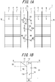
- FIG. 1(a) is a developed view of a tread pattern of the disclosed pneumatic tire according to an embodiment thereof.
- a tread surface 1 of the pneumatic tire includes: a central circumferential groove 2 extending along the tire circumferential direction on a tire equatorial plane CL; a pair of intermediate circumferential grooves 3 extending along the tire circumferential direction across the central circumferential groove 2; a pair of lateral circumferential grooves 4 extending along the tire circumferential direction, on the tire width direction outside of the intermediate circumferential grooves 3; an intermediate widthwise groove 5 extending along the tire width direction while communicating with the intermediate circumferential grooves 3 and with the lateral circumferential grooves 4; and a lateral widthwise groove 6 extending along the tire width direction while communicating with the lateral circumferential grooves 4 and extending toward a tread surface end TE.
- the central circumferential groove 2 and the intermediate circumferential grooves 3 together define a pair of rib-shaped central land portions 7 across the tire equatorial plane CL.
- the intermediate circumferential grooves 3, the lateral circumferential grooves 4, and the intermediate widthwise grooves 5 together define block-shaped intermediate land portions 8.
- the lateral circumferential grooves 4 and the lateral widthwise grooves 6 together define block-shaped lateral land portions 9.
- the tread pattern is illustrated in the drawing by way of example, and the present disclosure may be applicable to a rib-based pattern and a block-based pattern, or any other arbitrary patterns.
- the intermediate widthwise groove 5 and the lateral widthwise groove 6 may be inclined with respect to the tire width direction, and may have a non-constant width.
- the lateral widthwise groove 6 does not need to be communicating with the tread surface end TE.
- narrow grooves 10 are formed extending in a direction inclined with respect to the tire circumferential direction.
- the narrow grooves 10 each terminate at one end 10a within the rib-shaped central land portions 7 while opening at the other end 10b to the central circumferential groove 2.
- the narrow grooves 10 each have a groove width W1 that is smaller (narrower) than a groove depth D1 in the A-A section.
- the groove width W1 is in the tire circumferential direction.
- the narrow grooves 10 each have an air inflow part 11 opening to the tread surface 1, the air inflow part 11 being formed on one of groove walls 10c facing each other in the tire circumferential direction.
- the narrow grooves 10 each have a maximum depth D1 and the air inflow part 11 has a maximum depth D2, where the D1 and the D2 satisfy the following condition: 1 ⁇ D1/D2 ⁇ 15.
- the air inflow part 11 is formed by cutting out a corner 12 defined by the tread surface 1 and the groove wall 10c, at least in part in the longitudinal direction of the narrow groove 10.
- the narrow grooves 10 may be formed, other than in the rib-shaped central land portions 7, in the block-shaped intermediate land portions 8 or in the block-shaped lateral land portions 9. Further, the narrow groove 10 may be inclined at an arbitrary angle ⁇ (0 ⁇ ⁇ ⁇ 90°) relative to the tire circumferential direction, and the plurality of tire grooves 10 may not be formed as being parallel to one another. In the illustrated example, the narrow grooves 10 are each terminated at one end 10a thereof within the rib-shaped central land portions 7 and open to the central circumferential groove 2 at the other end 10b thereof. However, the narrow groove may only be terminated at one end in the longitudinal direction thereof within the land portion.
- the position and the shape of the air inflow part 11 are illustrated by way of example, and the disclosed air inflow part 11 may be disposed at one end within a land portion of the narrow groove in the longitudinal direction of the narrow groove.
- the air inflow part 11 may be formed in a parallelogram in plane shape in the tread surface developed view on the tread, with a pair of opposite sides being parallel to the groove wall 10c of the narrow groove 10 while the other pair of opposite sides being parallel to the tire circumferential direction.
- the air inflow part 11 may also be formed in another parallelogram with a pair of opposite sides being parallel to the groove wall 10c of the narrow groove 10 while the other pair of opposite sides being inclined relative to the tire circumferential direction.
- the air inflow part 11 may be trapezoidal, semicircular, triangular, or the like in plane shape when viewed from the tread surface.
- wind air flows around the tire in a direction opposite to the rotation direction of the tire.
- the wind may be taken into the grooves formed on the tread surface 1, to thereby dissipate heat from the tread portion, which lowers the temperature of the tread portion.
- the grooves formed on the tread surface 1 are large in width, wind can be taken into the grooves but the land portion is reduced in rigidity, leading to deterioration of antiwear performance and steering stability.
- the grooves formed on the tread surface 1 are small enough only not to affect rigidity of the land portion, the grooves cannot take wind thereinto. That is, most of the wind is not taken into the narrow groove 10, with only a part of the wind being taken into the narrow groove 10. However, even the wind that has been taken into the narrow groove 10 only passes through a shallow portion of the narrow groove 10 and is expelled from the narrow groove 10 without reaching the groove bottom of the narrow groove 10, which thus produces only a small effect of lowering the temperature of the tread portion.
- the air inflow part 11 is formed on the windward-side groove wall 10c of the narrow groove 10, that is, the tire is mounted onto a vehicle for use such that the groove wall 10c formed with the air inflow part 11 is disposed on the windward side, to thereby take most of the wind into the narrow groove 10 and allow the wind thus taken to reach close to the groove bottom. Meanwhile, the wind that has been taken into the narrow groove 10 flows out from the leeward-side edge. Further, the narrow groove 10 is terminated at one end 10a within the rib-shaped central land portions 7, which can maintain high rigidity in the land portion, as compared with an exemplary case where the narrow groove is opened at both ends thereof to the central circumferential groove 2 (and to the intermediate circumferential groove 3).
- the narrow groove 10 and the air flow part 11 may be formed such that the maximum depth D1 of the narrow groove 10 and the maximum depth D2 of the air inflow part 11 satisfy: 1 ⁇ D1/D2 ⁇ 15, to thereby improve the heat dissipation effect in the tread portion, while ensuring an appropriate rigidity in the land portion.
- the disclosed pneumatic tire produces a prominent effect when applied to a large tire for use in trucks, buses, and construction vehicles, which are otherwise susceptible to the problem of heat generation in the tread portion along with the increase in size.
- the disclosed pneumatic tire produces a further prominent effect when applied to a pneumatic tire for construction vehicles, because the tire is exposed on the vehicle side (opposite side to the contact surface that is in contact with the road surface) without being covered by the vehicle.
- the D1 and the D2 satisfy the following relation: 5 ⁇ D1/D2 ⁇ 10.
- the depth of the air inflow part 11 may preferably become maximum at the groove wall opening edge 11a that opens to the groove wall 10c of the narrow groove 10. This configuration makes the opening larger, allowing air to readily flow into the narrow groove 10.
- the air inflow part 11 may preferably have a side profile in section perpendicular to the longitudinal direction of the narrow groove where the air inflow part 11 gradually increases in depth from one end of the narrow groove 10 farther from the groove wall opening edge 11a of the narrow groove 10 toward the groove wall opening edge 11a that opens to the groove wall 10c of the narrow groove 10.
- This configuration can increase the wind inflow effect, and also suppress wasteful reduction of the volume of the land portion, which prevents reduction of rigidity in the land portion.
- the bottom face of the air inflow part 11 may be planar or curved.
- the depth of the air inflow part 11 may increase stepwise toward the groove wall opening edge 11a, or the depth of the air inflow part 11 may be constant.
- the air inflow parts 11 is formed on both of the groove walls 10c facing each other of the narrow groove 10, that is, the groove walls 10c on both sides.
- a wind flow is formed such that air flows into the narrow groove 10 from the air inflow part 11 formed on the windward-side groove wall 10c and passes through within the narrow groove 10, so as to flow out from the end of the leeward-side groove wall 10c.
- the air inflow parts 11 are respectively formed on both of the groove walls 10c of the narrow groove 10, a center of one of the air inflow parts 11 along the longitudinal direction of the narrow groove 10 at the groove wall opening edge 11a opening to the groove wall, the air inflow part 11 being formed on one of the groove walls of the narrow groove 10, is spaced apart in the longitudinal direction of the narrow groove 10 from a center of the other one of the air inflow parts 11 along the longitudinal direction of the narrow groove 10 at the groove wall opening edge 11a, the air inflow part 11 being formed on the other one of the groove walls of the narrow groove 10, so that the inflow parts 11 do not coincide with one another in position in the tire circumferential direction.
- the narrow groove 10 may possibly be formed in an arbitrary position on the rib-shaped central land portions 7.
- a distance W4 in the tire width direction from the intermediate circumferential groove 3 to the narrow groove 10 may preferably fall within a range of 5 % to 40 % with respect to a width W3 in the tire width direction of the rib-shaped central land portions 7.
- the narrow groove 10 should desirably be inclined at an angle of 45° or more and 90° or less in the tire circumferential direction.
- the groove width W1 is set to be smaller than the groove depth D1 for the following reason: that is, the narrow groove 10 having a larger depth and a smaller width can make it more easy to take air thereinto, which makes the disclosed effect more prominent. Wind may be taken into the groove with more ease along with an increase of the groove width W1, which however makes it difficult to ensure rigidity of the land portion.
- the air inflow part 11 even if being satisfactorily small in size relative to the size of the land portion, can still increase greatly the amount of air entering the narrow groove 10.
- the air inflow part 11 may be formed in a size enough to serve the purpose, without significantly reducing the volume of the land portion. Therefore, the air inflow part 11 may be formed with negligibly small impact on the antiwear performance and steering stability.
- the air inflow part 11 may preferably formed in a portion of the narrow groove 10 in the longitudinal direction. Specifically, the air inflow part 11 may preferably have a length L2 (length along the longitudinal direction of the narrow groove 10) of 5 mm or more and 1/2 or less of a length L1 of the narrow groove 10 along the longitudinal direction.
- the air inflow part 11 becomes smaller along with the wear of the tread portion, with the result that the effect of taking wind or the heat dissipation performance is reduced.
- the amount of heat to be generated in the tread portion also reduces along the wear of the tread portion, and thus, there is little need to design the air inflow part 11 of a brand new tire to be particularly large enough to withstand the wear.
- FIG. 2(a) illustrates, as a modified example of the narrow grooves and the air inflow part disclosed herein, narrow grooves 20b to 20e and air inflow parts 21b to 21e, arranged on a rib-shaped land portion 27 formed on the tread surface.
- FIG. 2(b) is a sectional view taken along the line B-B' of FIG. 2(a);
- FIG. 2(c) is a sectional view taken along the line C-C' of FIG. 2(a);
- FIG. 2(d) is a sectional view taken along the line D-D' of FIG. 2(a); and
- FIG. 2(e) is a sectional view taken along the line E-E' of FIG. 2(a) .
- the rib-shaped land portion 27 is disposed in between circumferential grooves 23 extending along the tire circumferential direction, where the rib-shaped land portion 27 has a widthwise center line that coincides with the tire equatorial plane CL. Further, the air inflow parts 21b to 21e are formed such that the centers M along the longitudinal direction of the narrow grooves 20b to 20e (at the groove wall opening edge 11a opening to the groove wall) are positioned on the widthwise center line of the rib-shaped land portion 27.
- FIGS. 2(b) to 2(e) each schematically illustrate by arrows the flow of air within the narrow grooves 20b to 20e.
- the narrow groove 20b extends along the tire width direction, and the narrow grooves 20c, 20d, 20e are inclined with respect to the tire width direction. Further, the narrow grooves 20b, 20c each terminate at both ends within the rib-shaped land portion 27 and are included by way of reference only. As illustrated therein, the narrow groove 20d opens at one end on the windward side to the circumferential groove 23 while the narrow groove 20e opens at one end on the leeward side to the circumferential groove 23, and each terminates at the other end thereof within the rib-shaped land portion 27.
- the air inflow part 21b may preferably be formed in a tire widthwise position of a portion to be cooled.
- air having flowed into the narrow groove 20c from the air inflow part 21c flows as being drawn to the leeward side toward the groove bottom as illustrated therein, and thus the heat dissipation effect becomes maximum in a region to the leeward side relative to the position immediately below the air inflow part 21b.
- the air inflow part 21c may preferably be formed on the windward side relative to the tire widthwise position of a portion to be cooled.
- the heat dissipation effect becomes maximum in a region to the leeward side relative to the position immediately below the air inflow part 21d, as in the case of the narrow groove 20c of FIG. 2(c) .
- air having flowed thereinto from the air inflow part 21d and air having flowed thereinto from the circumferential groove 23 meet with each other to stagnate, which forms a heat dissipation effect deteriorated region where the heat dissipation effect can hardly be obtained.
- the air inflow part 21d may preferably be formed on the windward side relative to the tire widthwise position of a portion to be cooled.
- the air inflow part 21d may preferably be disposed all the way to the windward side (i.e., opening side) as far as possible. Further, when forming the air inflow part 21d, it may be preferred to suppress airflow from the circumferential groove 23; for example, the circumferential groove 23 itself may preferably be reduced in width, an opening may preferably be disposed on the leeward side, or the narrow groove may preferably be prevented from communicating with the tread surface edge.
- the heat dissipation effect becomes maximum in a region to the leeward side relative to the position immediately below the air inflow part 21e, as in the case of the narrow groove 20d of FIG. 2(d) .
- the narrow groove 21e opens on the leeward side, for which air is less likely to flow into from the circumferential groove 23, with the result that the heat dissipation effect deteriorate region shown in FIG. 2(d) is not formed.
- the air inflow part 21e may preferably be formed on the windward side relative to the tire widthwise position of a portion to be cooled.
- the air inflow part may desirably be arranged relative to the narrow groove, in consideration of the aforementioned air flows within the narrow groove, so that a region where the heat dissipation effect becomes maximum may be formed at a position which requires heat release. Even in a case where the position and the shape of the narrow groove and the air inflow part are different from those of FIGS. 2 , the most effective position to dispose the air inflow part may still be estimated based on the aforementioned consideration.
- FIG. 3 is a sectional view in the tire width direction, illustrating an internal structure of the disclosed pneumatic tire according to an embodiment thereof, in particular, a heavy load tire for a construction vehicle or the like.
- the tire 100 is larger in rubber gauge (rubber thickness) of a tread portion 500, as compared with a pneumatic tire to be mounted onto a passenger car or the like.
- the tire internal structure to be described in below is applicable to the respective tires each having the tread pattern illustrated with reference to FIG. 1 .
- the tire 100 satisfies the relation of DC/OD ⁇ 0.015, where OD represents the tire outer diameter and DC represents the rubber gauge of the tread portion 500 at a position of the tire equatorial plane C.
- the tire outer diameter OD refers to the diameter of the tire 100 at a portion where the outer diameter of the tire 100 becomes maximum (such portion generally corresponds to the tread portion 500 near the tire equatorial plane C).
- the rubber gauge DC (in the unit of mm) refers to the thickness of the tread portion 500 at the position of the tire equatorial plane C.
- the rubber gauge DC is exclusive of the thickness of a belt 300.
- the tire 100 includes a pair of bead cores 110, a carcass 200, and the belt 300 including a plurality of belt layers. Note that FIG. 3 illustrates the tire 100 only in half width, whereas the other half width of the tire 100 not shown is similarly structured.
- the bead core 110 is disposed in a bead portion 120.
- the bead core 110 is constituted of a bead wire (not shown).
- the carcass 200 constitutes the skeleton of the tire 100.
- the carcass 200 is positioned from the tread portion 500 to come across a buttress portion 900 and a sidewall portion 700 to the bead portion 120.
- the carcass 200 is disposed between the pair of bead cores 110 and has a toroidal shape.
- the carcass 200 in this embodiment is disposed around the bead core 110.
- the carcass 200 is in contact with the bead core 110.
- the carcass 200 is supported at both ends in the tire width direction twd by the pair of bead portions 120.
- the carcass 200 has a carcass cord that extends in a predetermined direction when viewed in plan from the tread surface 1 side.
- the carcass cord extends along the tire width direction twd.
- Steel wire may, for example, be used as the carcass cord.
- the belt 300 is disposed in the tread portion 500.
- the belt 300 is positioned on the outside of the carcass 200 in the tire radial direction trd.
- the belt 300 extends in the tire circumferential direction.
- the belt 300 has a belt cord that extends as being inclined with respect to a predetermined direction as a direction in which the carcass cord extends.
- a steel cord for example, may be used as the belt cord.
- the belt 300 including the plurality of belt layers includes: a first belt layer 301; a second belt layer 302; a third belt layer 303; a fourth belt layer 304; a fifth belt layer 305; and a sixth belt layer 306.
- the first belt layer 301 is positioned on the outside of the carcass 200 in the tire radial direction trd.
- the first belt layer 301 is positioned on the innermost side in the tire radial direction trd, among the plurality of belt layers forming the belt 300.
- the second belt layer 302 is positioned on the outside of the first belt layer 301 in the tire radial direction trd.
- the third belt layer 303 is positioned on the outside of the second belt layer 302 in the tire radial direction trd.
- the fourth belt layer 304 is positioned on the outside of the third belt layer 303 in the tire radial direction trd.
- the fifth belt layer 305 is positioned on the outside of the fourth belt layer 304 in the tire radial direction trd.
- the sixth belt layer 306 is positioned on the outside of the fifth belt layer 305 in the tire radial direction trd.
- the sixth belt layer 306 is positioned on the outermost side in the tire radial direction trd, among the plurality of belt layers forming the belt 300.
- the first belt layer 301, the second belt layer 302, the third belt layer 303, the fourth belt layer 304, the fifth belt layer 305, and the sixth belt layer 306 are arranged in the stated order from the inside to the outside.
- the first belt layer 301 and the second belt layer 302 each have a width (the width being measured along the tire width direction twd ; hereinafter the same) defined to be 25 % or more and 70 % or less of the tread width TW.
- the third belt layer 303 and the fourth belt layer 304 each have a width defined to be 55 % or more and 90 % or less of the tread width TW.
- the fifth belt layer 305 and the sixth belt layer 306 each have a width defined to be 60 % or more and 110 % or less of the tread width TW.
- the width of the fifth belt layer 305 is larger than the width of the third belt layer 303
- the width of the third belt layer 303 is equal to or larger than the width of the sixth belt layer 306
- the width of the sixth belt layer 306 is larger than the width of the fourth belt layer 304
- the width of the fourth belt layer 304 is larger than the width of the first belt layer 301
- the width of the first belt layer 301 is larger than the width of the second belt layer 302.
- the fifth belt layer 305 is largest in width and the second belt layer 302 is smallest in width.
- the belt 300 including the plurality of belt layers includes a shortest belt layer (i.e., the second belt layer 302) that is shortest in length in the tire width direction twd.
- the second belt layer 302 which is the shortest belt layer, has a belt end 300e serving as an end in the tire width direction twd.
- the belt cords of the first belt layer 301 and the second belt layer 302 are inclined at an angle of 70° or more and 85° or less with respect to the carcass cord.
- the belt cords of the third belt layer 303 and the fourth belt layer 304 are inclined at an angle of 50° or more and 75° or less with respect to the carcass cord.
- the belt cords of the fifth belt layer 305 and the sixth belt layer 306 are inclined at an angle of 50° or more and 70° or less.
- the belt 300 including the plurality of belt layers includes: an inner crossing belt group 300A; an intermediate crossing belt group 300B; and an outer crossing belt group 300C.
- the crossing belt groups 300A to 300C each refer to a group of a plurality of belt layers in which belt cords constituting the respective belt layers in each group cross one another between the belt layers adjacent to each other within the group (preferably across the tire equatorial plane), in plan view from the tread surface 1 side.
- the inner crossing belt group 300A includes a pair of belt layers, and positioned on the outside of the carcass 200 in the tire radial direction trd.
- the inner crossing belt group 300A is constituted of the first belt layer 301 and the second belt layer 302.
- the intermediate crossing belt group 300B includes a pair of belt layers, and positioned on the outside of the inner crossing belt group 300A in the tire radial direction trd.
- the intermediate crossing belt group 300B is constituted of the third belt layer 303 and the fourth belt layer 304.
- the outer crossing belt group 300C includes a pair of belt layers, and positioned on the outside of the intermediate crossing belt group 300B in the tire radial direction trd.
- the outer crossing belt group 300C is constituted of the fifth belt layer 305 and the sixth belt layer 306.
- the inner crossing belt group 300A has a width defined to be 25 % or more and 80 % or less of the tread width TW.
- the intermediate crossing belt group 300B has a width defined to be 55 % or more and 90 % or less of the tread width TW.
- the outer crossing belt group 300C has a width defined to be 60 % or more and 110 % or less of the tread width TW.
- the belt cord of the inner crossing belt group 300A is inclined at an angle of 70° or more and 85° or less with respect to the carcass cord.
- the belt cord of the intermediate crossing belt group 300B is inclined at an angle of 50° or more and 75° or less with respect to the carcass cord.
- the belt cord of the outer crossing belt group 300C is inclined at an angle of 50° or more and 70° or less with respect to the carcass cord.
- the belt cord of the inner crossing belt group 300A is inclined with respect to the carcass cord at an angle larger than those of the rest of the belt cords.
- the belt cord of the intermediate crossing belt group 300B is inclined with respect to the carcass cord at an angle equal to or larger than that of the belt cord of the outer crossing belt group 300C.
- the circumferential groove (intermediate circumferential groove) 3 is formed to have a length DL of 200 mm or less which is measured along the tire width direction twd from the belt end 300e to the tire width direction innermost position (i.e., bent part to the inside in the tire width direction) of a groove width center line WL passing through the widthwise center of the circumferential groove 3 when viewed in plan from the tread surface 1 side of the tire 100.
- FIG. 4(a) when the tire rotates, wind flows around the tire in a direction opposite to the traveling direction of the tire.
- the wind may be taken into the grooves formed on the tread surface 1, to thereby dissipate heat from the tread portion, which lowers the temperature of the tread portion.
- the grooves formed on the tread surface 1 are large in width, wind can be taken into the grooves but the land portion is reduced in rigidity, leading to deterioration of antiwear performance and steering stability.
- the grooves formed on the tread surface 1 are small enough in width only not to affect rigidity of the land portion, the grooves cannot take wind thereinto.
- FIG. 4(b) which illustrates a portion denoted by X of FIG.
- the air inflow part 11 is formed on the windward-side groove wall of the narrow groove 10 as illustrated in FIG. 4(c) , to thereby take most of the wind into the narrow groove 10 and allow the wind thus taken into the narrow groove 10 to reach the groove bottom. Further, when the air inflow part 11 is also formed on the leeward-side groove wall, the wind is allowed to flow out from the air inflow part 11 thus formed. Note that even if the air inflow part 11 is not formed on the leeward-side groove wall, the wind having nowhere to go at the end of the narrow groove 10 can still flow out from the edge of the leeward-side groove wall. This configuration is capable of increasing the effect of lowering the temperature of the tread portion.
- the disclosed effect becomes prominent when applied to a pneumatic tire for a construction vehicle because the tire has a portion on the vehicle side (opposite side to the tread side) denoted by X in the drawing which is exposed without being covered by the vehicle.
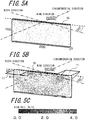
- FIG. 5(a) illustrates the narrow groove 10 inclined at an angle of 30° with respect to the tire width direction, which is not provided with the air inflow part 11.
- FIG. 5(b) illustrates the narrow groove 10 provided with the air inflow parts 11 on the windward side and the leeward side.
- FIG. 5(c) shows the flow rate.
- the narrow groove 10 is in a size of 200 mm in length in the longitudinal direction, 10 mm in width, and 100 mm in depth, and inclined with respect to the tire width direction at an angle of 30°.
- the air inflow part 11 is in a size of 50 mm in length (length along the longitudinal direction of the narrow groove 10), 50 mm in width, and 20 mm in depth at the deepest part.
- the narrow groove 10 may preferably close during ground contact. Specifically, the narrow groove 10 may preferably have a width of 10 mm to 20 mm. When the narrow groove 10 closes upon ground contact, the rib-shaped central land portion 7 becomes continuous. This enhances rigidity of the land portion to thereby improve antiwear performance.
- FIGS. 6 to 9 Various modified examples of the air inflow part 11 are described in below, referring to FIGS. 6 to 9 .
- the wind directions are indicated by the arrows.
- the air inflow part 11 may be formed, as illustrated in FIG. 6(a) , on the groove wall at one end which receives wind first, of both ends of the narrow groove 10, or may be formed, as illustrated in FIG. 6(b) , on the groove wall at the other end which receives wind last. Otherwise, as illustrated in FIG. 6(c) , the air inflow part 11 may be formed in the central region of the narrow groove 10.
- the air inflow parts 11 are respectively formed on the groove walls on both of the windward and leeward sides of the narrow groove 10, and a center point A of one of the air inflow parts 11 along the longitudinal direction of the narrow groove 10, the air inflow part 11 being formed on one of the groove walls of the narrow groove 10, is spaced apart in the longitudinal direction of the narrow groove 10 from a center point B of the other one of the air inflow parts 11 along the longitudinal direction of the narrow groove 10, the air inflow part 11 being formed on the other one of the groove walls of the narrow groove 10, so that the inflow parts do not overlap one another with respect to the tire circumferential direction (direction in which wind is coming from).
- the air inflow parts 11 are formed on both sides of the narrow groove 10 as illustrated in FIGS. 7(a) and 7(b) , and may preferably be formed in the central region as being displaced from each other as illustrated in FIGS. 7(c) and 7(d) . Otherwise, as illustrated in FIG. 7(e) , the air inflow parts 11 may be also formed side by side in the central region of the narrow groove 10; that is, the point A and the point B may be arranged without being spaced apart from each other in the longitudinal direction of the narrow groove 10.
- a planar shape of the air inflow part 11 viewed from the tread surface may be a parallelogram with a pair of opposite sides parallel to the wall of the narrow groove 10 and the other pair of opposite sides parallel to the tire circumferential direction as illustrated in FIG. 8(a) , or may be parallelogram with a pair of opposite sides parallel to the wall of the narrow groove 10 and the other pair of opposite sides inclined with respect to the tire circumferential direction as illustrated in FIGS. 8(b) and 8(c) . Further, as illustrated in FIG.
- the planar shape of the air inflow part 11 may be a trapezoid with the lower base opening to the wall of the narrow groove 10 and the upper base being positioned on the farther side from the wall of the narrow groove 10; that is, the trapezoid gradually reduces in length in the tire width direction from the wall side of the narrow groove 10.
- the planar shape of the air inflow part 10 may be a trapezoid with the upper base opening to the wall of the narrow groove 10 and the lower base positioned on the farther side from the wall of the narrow groove 10; that is, the trapezoid gradually increases in length in the tire width direction from the wall of the narrow groove 10. Still alternatively, as illustrated in FIG.
- the planar shape of the air inflow part 11 may be a trapezoid shown in FIG. 8(e) , with two sides other than the upper base and the lower base being curved. Otherwise, the planar shape of the air inflow part 11 may be semicircular as illustrated in FIG. 8(g) , or may be triangular as illustrated in FIG. 8(h) .
- a side profile of the air inflow part 11 in section perpendicular to the longitudinal direction of the narrow groove may preferably be formed such that, as illustrated in FIGS. 9(a) to 9(d) , the depth of the air inflow part 11 gradually increases from one side (point A in the drawing) farther from the wall of the narrow groove 10 to the other side (point B in the drawing) opening to the wall of the narrow groove 10, where the air inflow part 11 becomes deepest.
- the bottom plane of the air inflow part 11 may be flat as illustrated in FIG. 9(a) , or may be curved as illustrated in FIGS. 9(b) to 9(d) . Further, as illustrated in FIG.
- the depth of the air inflow part 11 may increase stepwise from the point A to the point B.
- the air inflow part 11 may be have a depth that is constant between the point A and the point C and gradually increases from the point C to the point B, or as illustrated in FIG. 9(h) , the air inflow part 11 may have a depth that gradually increases from the point A to the point C and is constant from the point C to the point B.
- the air inflow part 11 may have a depth that is constant from the point A to the point B.
- the longitudinal direction of the narrow groove 10 is inclined at an angle of 90° with respect to the tire circumferential direction
- the narrow groove 10 has a length of L1 of 1000 mm in the longitudinal direction thereof
- the narrow groove 10 has a groove width W1 of 20 mm
- the air inflow part 11 has a length L2 of 250 mm
- the air inflow part 11 has a width W2 of 50 mm.
Landscapes
- Engineering & Computer Science (AREA)
- Mechanical Engineering (AREA)
- Tires In General (AREA)
Claims (5)
- Luftreifen umfassend
eine schmale Rille (10), welche auf einer Lauffläche (1) gebildet ist, wobei die schmale Rille (10) sich in einer Richtung erstreckt, welche relativ zur Reifenumfangsrichtung geneigt ist und eine Rillenbreite (W1) aufweist, welche kleiner als eine Rillentiefe (D1) ist,
wobei die schmale Rille (10) an einem Ende innerhalb eines Stegabschnitts (7, 8, 9) endet und die schmale Rille (10) sich am anderen Ende in eine Umfangsrille (2, 3, 4) öffnet,
wobei die schmale Rille (10) einen Lufteinlassteil (11) aufweist, welcher auf zumindest einer der Rillenwände gebildet ist, welche sich in der Reifenumfangsrichtung gegenüberstehen, wobei der Lufteinlassteil (11) sich zur Lauffläche hin öffnet,
wobei der Lufteinlassteil (11) an dem einen Ende innerhalb eines Stegabschnitts (7, 8, 9) der schmalen Rille (10) in der Längsrichtung der schmalen Rille (10) gebildet ist,
wobei die schmale Rille (10) eine maximale Tiefe D1 aufweist und der Lufteinlassteil (11) eine maximale Tiefe D2 aufweist, wobei D1 und D2 die folgende Beziehung erfüllen:
wobei der Mittelpunkt eines der Lufteinlassteile (11) entlang der Längsrichtung der schmalen Rille (10) am Rand (11a) der Rillenwandöffnung, welcher sich zur Rillenwand (10c) öffnet, wobei der Lufteinlassteil (11) auf einer der Rillenwände (10c) der schmalen Rille (10) gebildet ist, in der Längsrichtung der schmalen Rille (10) von einem Mittelpunkt des anderen der Lufteinlassteile (11) entlang der Längsrichtung der schmalen Rille (10) am Rand (11a) der Rillenwandöffnung beabstandet ist, wobei der Lufteinlassteil (11) auf der anderen der Rillenwände (10c) der schmalen Rille (10) gebildet ist, dadurch gekennzeichnet, dass
die Rillenbreite (W1) der schmalen Rille (10) entlang der Erstreckungsrichtung der schmalen Rille (10) konstant ist. - Luftreifen nach Anspruch 1, wobei jeder Lufteinlassteil (11), wenn von der Lauffläche (1) gesehen, ein Paar von gegenüberliegenden Seiten aufweist, welche zur Wand der schmalen Rille (10) parallel sind.
- Luftreifen nach Anspruch 1, wobei jeder Lufteinlassteil (11), wenn von der Lauffläche (1) gesehen, ein Parallelogramm ist, welches ein Paar von gegenüberliegenden Seiten aufweist, welche parallel zur Wand der schmalen Rille (10) verlaufen und wobei das andere Paar von gegenüberliegenden Seiten sich parallel zur Reifenumfangsrichtung erstreckt.
- Luftreifen nach Anspruch 1, wobei jeder Lufteinlassteil (11) eine Breite aufweist, welche ihr Maximum am Rand (11a) der Rillenwandöffnung erreicht, welche sich zur Rillenwand (10c) der schmalen Rille (10) hin öffnet.
- Luftreifen nach Anspruch 4, wobei jeder Lufteinlassteil (11) eine Tiefe aufweist, welche sich allmählich zum Rand (11a) der Rillenwandöffnung hin erhöht.
Applications Claiming Priority (2)
| Application Number | Priority Date | Filing Date | Title |
|---|---|---|---|
| JP2013050297A JP5799043B2 (ja) | 2013-03-13 | 2013-03-13 | 空気入りタイヤ |
| PCT/JP2014/057634 WO2014142348A1 (ja) | 2013-03-13 | 2014-03-13 | 空気入りタイヤ |
Publications (3)
| Publication Number | Publication Date |
|---|---|
| EP2974889A4 EP2974889A4 (de) | 2016-01-20 |
| EP2974889A1 EP2974889A1 (de) | 2016-01-20 |
| EP2974889B1 true EP2974889B1 (de) | 2018-05-30 |
Family
ID=51536992
Family Applications (1)
| Application Number | Title | Priority Date | Filing Date |
|---|---|---|---|
| EP14765502.1A Active EP2974889B1 (de) | 2013-03-13 | 2014-03-13 | Luftreifen |
Country Status (8)
| Country | Link |
|---|---|
| US (1) | US10730350B2 (de) |
| EP (1) | EP2974889B1 (de) |
| JP (1) | JP5799043B2 (de) |
| CN (1) | CN105050832B (de) |
| BR (1) | BR112015022870A2 (de) |
| CL (1) | CL2015002618A1 (de) |
| ES (1) | ES2684072T3 (de) |
| WO (1) | WO2014142348A1 (de) |
Families Citing this family (6)
| Publication number | Priority date | Publication date | Assignee | Title |
|---|---|---|---|---|
| JP6847695B2 (ja) * | 2017-02-13 | 2021-03-24 | 株式会社ブリヂストン | 建設車両用タイヤ |
| JP6872923B2 (ja) * | 2017-02-13 | 2021-05-19 | 株式会社ブリヂストン | 建設車両用タイヤ |
| JP6854221B2 (ja) * | 2017-08-30 | 2021-04-07 | 株式会社ブリヂストン | 建設車両用タイヤ |
| JP1600980S (de) * | 2017-08-31 | 2018-04-02 | ||
| JP2020001449A (ja) * | 2018-06-25 | 2020-01-09 | 株式会社ブリヂストン | タイヤ |
| JP7763715B2 (ja) * | 2022-05-19 | 2025-11-04 | 株式会社ブリヂストン | 建設車両用タイヤ |
Citations (4)
| Publication number | Priority date | Publication date | Assignee | Title |
|---|---|---|---|---|
| US3998256A (en) * | 1973-07-05 | 1976-12-21 | Compagnie Generale Des Etablissements Michelin, Raison Sociale Michelin & Cie | Tire with tread blocks having identical, circular ellipses of inertia |
| EP2208622A1 (de) * | 2007-10-12 | 2010-07-21 | Bridgestone Corporation | Luftreifen |
| EP2457745A1 (de) * | 2010-11-24 | 2012-05-30 | Continental Reifen Deutschland GmbH | Fahrzeugluftreifen |
| EP2636544A1 (de) * | 2012-03-05 | 2013-09-11 | Continental Reifen Deutschland GmbH | Fahrzeugluftreifen |
Family Cites Families (22)
| Publication number | Priority date | Publication date | Assignee | Title |
|---|---|---|---|---|
| DE69112660T2 (de) * | 1990-02-15 | 1996-02-01 | Sumitomo Rubber Ind | Luftreifen. |
| JPH0596913A (ja) * | 1991-10-08 | 1993-04-20 | Bridgestone Corp | 重荷重用空気入りタイヤ |
| JP3200506B2 (ja) * | 1993-08-12 | 2001-08-20 | 横浜ゴム株式会社 | 重荷重用空気入りラジアルタイヤ |
| DE19651792A1 (de) | 1996-12-12 | 1998-06-18 | Continental Ag | Fahrzeugreifen mit einer Lauffläche mit Einschnitten |
| JP4227239B2 (ja) * | 1999-03-18 | 2009-02-18 | 株式会社ブリヂストン | 空気入りタイヤ |
| JP3999521B2 (ja) | 2002-01-15 | 2007-10-31 | 株式会社ブリヂストン | 空気入りタイヤ |
| DE502004011794D1 (de) * | 2004-03-26 | 2010-12-02 | Continental Reifen Deutschland | Fahrzeugluftreifen |
| JP4602782B2 (ja) * | 2005-02-03 | 2010-12-22 | 株式会社ブリヂストン | 重荷重用空気入りタイヤ |
| JP4938316B2 (ja) * | 2006-01-20 | 2012-05-23 | 株式会社ブリヂストン | 建設車両用タイヤ |
| JP4943717B2 (ja) * | 2006-03-01 | 2012-05-30 | 株式会社ブリヂストン | 空気入りタイヤ |
| JP5052317B2 (ja) * | 2007-12-10 | 2012-10-17 | 株式会社ブリヂストン | 空気入りタイヤ |
| FR2926124B1 (fr) * | 2008-01-08 | 2011-01-14 | Capital Innovation | Robinet mitigeur double. |
| JP5435877B2 (ja) * | 2008-01-31 | 2014-03-05 | 株式会社ブリヂストン | 空気入りタイヤ |
| JP5265212B2 (ja) * | 2008-02-12 | 2013-08-14 | 株式会社ブリヂストン | 重荷重用空気入りラジアルタイヤ |
| JP5297778B2 (ja) * | 2008-02-27 | 2013-09-25 | 株式会社ブリヂストン | 空気入りタイヤ |
| JP5099914B2 (ja) * | 2008-10-03 | 2012-12-19 | 東洋ゴム工業株式会社 | 空気入りタイヤ |
| JP4697336B2 (ja) | 2009-02-20 | 2011-06-08 | 横浜ゴム株式会社 | 空気入りタイヤ |
| FR2943728B1 (fr) * | 2009-03-24 | 2014-07-11 | Peugeot Citroen Automobiles Sa | Procede de controle des emissions polluantes d'un moteur a combustion, groupe motopropulseur et vehicule equipe de ce groupe motopropulseur |
| EP2896513B1 (de) * | 2009-07-27 | 2017-03-29 | Bridgestone Corporation | Reifen für Baufahrzeug |
| FR2956357B1 (fr) * | 2010-02-12 | 2012-05-18 | Michelin Soc Tech | Pneumatique pour vehicules a deux roues comportant une bande de roulement presentant des incisions. |
| JP5603670B2 (ja) * | 2010-06-18 | 2014-10-08 | 株式会社ブリヂストン | タイヤ |
| CN103796845A (zh) * | 2011-09-09 | 2014-05-14 | 株式会社普利司通 | 充气轮胎 |
-
2013
- 2013-03-13 JP JP2013050297A patent/JP5799043B2/ja not_active Expired - Fee Related
-
2014
- 2014-03-13 ES ES14765502.1T patent/ES2684072T3/es active Active
- 2014-03-13 CN CN201480013827.4A patent/CN105050832B/zh active Active
- 2014-03-13 WO PCT/JP2014/057634 patent/WO2014142348A1/ja not_active Ceased
- 2014-03-13 EP EP14765502.1A patent/EP2974889B1/de active Active
- 2014-03-13 US US14/773,831 patent/US10730350B2/en active Active
- 2014-03-13 BR BR112015022870A patent/BR112015022870A2/pt active Search and Examination
-
2015
- 2015-09-11 CL CL2015002618A patent/CL2015002618A1/es unknown
Patent Citations (4)
| Publication number | Priority date | Publication date | Assignee | Title |
|---|---|---|---|---|
| US3998256A (en) * | 1973-07-05 | 1976-12-21 | Compagnie Generale Des Etablissements Michelin, Raison Sociale Michelin & Cie | Tire with tread blocks having identical, circular ellipses of inertia |
| EP2208622A1 (de) * | 2007-10-12 | 2010-07-21 | Bridgestone Corporation | Luftreifen |
| EP2457745A1 (de) * | 2010-11-24 | 2012-05-30 | Continental Reifen Deutschland GmbH | Fahrzeugluftreifen |
| EP2636544A1 (de) * | 2012-03-05 | 2013-09-11 | Continental Reifen Deutschland GmbH | Fahrzeugluftreifen |
Also Published As
| Publication number | Publication date |
|---|---|
| US10730350B2 (en) | 2020-08-04 |
| JP2014172599A (ja) | 2014-09-22 |
| CN105050832A (zh) | 2015-11-11 |
| US20160016438A1 (en) | 2016-01-21 |
| EP2974889A4 (de) | 2016-01-20 |
| JP5799043B2 (ja) | 2015-10-21 |
| EP2974889A1 (de) | 2016-01-20 |
| BR112015022870A2 (pt) | 2017-07-18 |
| ES2684072T3 (es) | 2018-10-01 |
| CL2015002618A1 (es) | 2016-04-01 |
| WO2014142348A1 (ja) | 2014-09-18 |
| CN105050832B (zh) | 2017-12-15 |
Similar Documents
| Publication | Publication Date | Title |
|---|---|---|
| EP2974888B1 (de) | Luftreifen | |
| EP2974887B1 (de) | Luftreifen | |
| EP2974889B1 (de) | Luftreifen | |
| EP3017966B1 (de) | Schwerlastluftreifen | |
| JP5007173B2 (ja) | 空気入りタイヤ | |
| EP2974886B1 (de) | Luftreifen | |
| JP5966348B2 (ja) | 空気入りタイヤ | |
| US10723179B2 (en) | Tire | |
| JP6603470B2 (ja) | タイヤ | |
| JP2021024523A (ja) | 空気入りタイヤ | |
| US20180072106A1 (en) | Tire | |
| EP2985156A1 (de) | Luftreifen | |
| JP5985005B2 (ja) | 空気入りタイヤ | |
| JP6060138B2 (ja) | 空気入りタイヤ | |
| JP2014213618A (ja) | 空気入りタイヤ | |
| CN105431306A (zh) | 航空器轮胎 |
Legal Events
| Date | Code | Title | Description |
|---|---|---|---|
| PUAI | Public reference made under article 153(3) epc to a published international application that has entered the european phase |
Free format text: ORIGINAL CODE: 0009012 |
|
| 17P | Request for examination filed |
Effective date: 20150911 |
|
| A4 | Supplementary search report drawn up and despatched |
Effective date: 20151217 |
|
| AK | Designated contracting states |
Kind code of ref document: A1 Designated state(s): AL AT BE BG CH CY CZ DE DK EE ES FI FR GB GR HR HU IE IS IT LI LT LU LV MC MK MT NL NO PL PT RO RS SE SI SK SM TR |
|
| AX | Request for extension of the european patent |
Extension state: BA ME |
|
| DAX | Request for extension of the european patent (deleted) | ||
| STAA | Information on the status of an ep patent application or granted ep patent |
Free format text: STATUS: EXAMINATION IS IN PROGRESS |
|
| 17Q | First examination report despatched |
Effective date: 20161107 |
|
| GRAP | Despatch of communication of intention to grant a patent |
Free format text: ORIGINAL CODE: EPIDOSNIGR1 |
|
| STAA | Information on the status of an ep patent application or granted ep patent |
Free format text: STATUS: GRANT OF PATENT IS INTENDED |
|
| INTG | Intention to grant announced |
Effective date: 20171204 |
|
| GRAS | Grant fee paid |
Free format text: ORIGINAL CODE: EPIDOSNIGR3 |
|
| GRAA | (expected) grant |
Free format text: ORIGINAL CODE: 0009210 |
|
| STAA | Information on the status of an ep patent application or granted ep patent |
Free format text: STATUS: THE PATENT HAS BEEN GRANTED |
|
| AK | Designated contracting states |
Kind code of ref document: B1 Designated state(s): AL AT BE BG CH CY CZ DE DK EE ES FI FR GB GR HR HU IE IS IT LI LT LU LV MC MK MT NL NO PL PT RO RS SE SI SK SM TR |
|
| REG | Reference to a national code |
Ref country code: GB Ref legal event code: FG4D |
|
| REG | Reference to a national code |
Ref country code: CH Ref legal event code: EP |
|
| REG | Reference to a national code |
Ref country code: AT Ref legal event code: REF Ref document number: 1003223 Country of ref document: AT Kind code of ref document: T Effective date: 20180615 |
|
| REG | Reference to a national code |
Ref country code: IE Ref legal event code: FG4D |
|
| REG | Reference to a national code |
Ref country code: DE Ref legal event code: R096 Ref document number: 602014026290 Country of ref document: DE |
|
| REG | Reference to a national code |
Ref country code: ES Ref legal event code: FG2A Ref document number: 2684072 Country of ref document: ES Kind code of ref document: T3 Effective date: 20181001 |
|
| REG | Reference to a national code |
Ref country code: NL Ref legal event code: MP Effective date: 20180530 |
|
| REG | Reference to a national code |
Ref country code: LT Ref legal event code: MG4D |
|
| PG25 | Lapsed in a contracting state [announced via postgrant information from national office to epo] |
Ref country code: SE Free format text: LAPSE BECAUSE OF FAILURE TO SUBMIT A TRANSLATION OF THE DESCRIPTION OR TO PAY THE FEE WITHIN THE PRESCRIBED TIME-LIMIT Effective date: 20180530 Ref country code: LT Free format text: LAPSE BECAUSE OF FAILURE TO SUBMIT A TRANSLATION OF THE DESCRIPTION OR TO PAY THE FEE WITHIN THE PRESCRIBED TIME-LIMIT Effective date: 20180530 Ref country code: NO Free format text: LAPSE BECAUSE OF FAILURE TO SUBMIT A TRANSLATION OF THE DESCRIPTION OR TO PAY THE FEE WITHIN THE PRESCRIBED TIME-LIMIT Effective date: 20180830 Ref country code: FI Free format text: LAPSE BECAUSE OF FAILURE TO SUBMIT A TRANSLATION OF THE DESCRIPTION OR TO PAY THE FEE WITHIN THE PRESCRIBED TIME-LIMIT Effective date: 20180530 Ref country code: CY Free format text: LAPSE BECAUSE OF FAILURE TO SUBMIT A TRANSLATION OF THE DESCRIPTION OR TO PAY THE FEE WITHIN THE PRESCRIBED TIME-LIMIT Effective date: 20180530 Ref country code: BG Free format text: LAPSE BECAUSE OF FAILURE TO SUBMIT A TRANSLATION OF THE DESCRIPTION OR TO PAY THE FEE WITHIN THE PRESCRIBED TIME-LIMIT Effective date: 20180830 |
|
| PG25 | Lapsed in a contracting state [announced via postgrant information from national office to epo] |
Ref country code: GR Free format text: LAPSE BECAUSE OF FAILURE TO SUBMIT A TRANSLATION OF THE DESCRIPTION OR TO PAY THE FEE WITHIN THE PRESCRIBED TIME-LIMIT Effective date: 20180831 Ref country code: RS Free format text: LAPSE BECAUSE OF FAILURE TO SUBMIT A TRANSLATION OF THE DESCRIPTION OR TO PAY THE FEE WITHIN THE PRESCRIBED TIME-LIMIT Effective date: 20180530 Ref country code: LV Free format text: LAPSE BECAUSE OF FAILURE TO SUBMIT A TRANSLATION OF THE DESCRIPTION OR TO PAY THE FEE WITHIN THE PRESCRIBED TIME-LIMIT Effective date: 20180530 Ref country code: HR Free format text: LAPSE BECAUSE OF FAILURE TO SUBMIT A TRANSLATION OF THE DESCRIPTION OR TO PAY THE FEE WITHIN THE PRESCRIBED TIME-LIMIT Effective date: 20180530 |
|
| REG | Reference to a national code |
Ref country code: AT Ref legal event code: MK05 Ref document number: 1003223 Country of ref document: AT Kind code of ref document: T Effective date: 20180530 |
|
| PG25 | Lapsed in a contracting state [announced via postgrant information from national office to epo] |
Ref country code: NL Free format text: LAPSE BECAUSE OF FAILURE TO SUBMIT A TRANSLATION OF THE DESCRIPTION OR TO PAY THE FEE WITHIN THE PRESCRIBED TIME-LIMIT Effective date: 20180530 |
|
| PG25 | Lapsed in a contracting state [announced via postgrant information from national office to epo] |
Ref country code: SK Free format text: LAPSE BECAUSE OF FAILURE TO SUBMIT A TRANSLATION OF THE DESCRIPTION OR TO PAY THE FEE WITHIN THE PRESCRIBED TIME-LIMIT Effective date: 20180530 Ref country code: DK Free format text: LAPSE BECAUSE OF FAILURE TO SUBMIT A TRANSLATION OF THE DESCRIPTION OR TO PAY THE FEE WITHIN THE PRESCRIBED TIME-LIMIT Effective date: 20180530 Ref country code: AT Free format text: LAPSE BECAUSE OF FAILURE TO SUBMIT A TRANSLATION OF THE DESCRIPTION OR TO PAY THE FEE WITHIN THE PRESCRIBED TIME-LIMIT Effective date: 20180530 Ref country code: PL Free format text: LAPSE BECAUSE OF FAILURE TO SUBMIT A TRANSLATION OF THE DESCRIPTION OR TO PAY THE FEE WITHIN THE PRESCRIBED TIME-LIMIT Effective date: 20180530 Ref country code: EE Free format text: LAPSE BECAUSE OF FAILURE TO SUBMIT A TRANSLATION OF THE DESCRIPTION OR TO PAY THE FEE WITHIN THE PRESCRIBED TIME-LIMIT Effective date: 20180530 Ref country code: RO Free format text: LAPSE BECAUSE OF FAILURE TO SUBMIT A TRANSLATION OF THE DESCRIPTION OR TO PAY THE FEE WITHIN THE PRESCRIBED TIME-LIMIT Effective date: 20180530 Ref country code: CZ Free format text: LAPSE BECAUSE OF FAILURE TO SUBMIT A TRANSLATION OF THE DESCRIPTION OR TO PAY THE FEE WITHIN THE PRESCRIBED TIME-LIMIT Effective date: 20180530 |
|
| PG25 | Lapsed in a contracting state [announced via postgrant information from national office to epo] |
Ref country code: IT Free format text: LAPSE BECAUSE OF FAILURE TO SUBMIT A TRANSLATION OF THE DESCRIPTION OR TO PAY THE FEE WITHIN THE PRESCRIBED TIME-LIMIT Effective date: 20180530 Ref country code: SM Free format text: LAPSE BECAUSE OF FAILURE TO SUBMIT A TRANSLATION OF THE DESCRIPTION OR TO PAY THE FEE WITHIN THE PRESCRIBED TIME-LIMIT Effective date: 20180530 |
|
| REG | Reference to a national code |
Ref country code: DE Ref legal event code: R097 Ref document number: 602014026290 Country of ref document: DE |
|
| PLBE | No opposition filed within time limit |
Free format text: ORIGINAL CODE: 0009261 |
|
| STAA | Information on the status of an ep patent application or granted ep patent |
Free format text: STATUS: NO OPPOSITION FILED WITHIN TIME LIMIT |
|
| 26N | No opposition filed |
Effective date: 20190301 |
|
| PG25 | Lapsed in a contracting state [announced via postgrant information from national office to epo] |
Ref country code: SI Free format text: LAPSE BECAUSE OF FAILURE TO SUBMIT A TRANSLATION OF THE DESCRIPTION OR TO PAY THE FEE WITHIN THE PRESCRIBED TIME-LIMIT Effective date: 20180530 |
|
| REG | Reference to a national code |
Ref country code: DE Ref legal event code: R119 Ref document number: 602014026290 Country of ref document: DE |
|
| PG25 | Lapsed in a contracting state [announced via postgrant information from national office to epo] |
Ref country code: MC Free format text: LAPSE BECAUSE OF FAILURE TO SUBMIT A TRANSLATION OF THE DESCRIPTION OR TO PAY THE FEE WITHIN THE PRESCRIBED TIME-LIMIT Effective date: 20180530 |
|
| REG | Reference to a national code |
Ref country code: CH Ref legal event code: PL |
|
| GBPC | Gb: european patent ceased through non-payment of renewal fee |
Effective date: 20190313 |
|
| PG25 | Lapsed in a contracting state [announced via postgrant information from national office to epo] |
Ref country code: LU Free format text: LAPSE BECAUSE OF NON-PAYMENT OF DUE FEES Effective date: 20190313 Ref country code: AL Free format text: LAPSE BECAUSE OF FAILURE TO SUBMIT A TRANSLATION OF THE DESCRIPTION OR TO PAY THE FEE WITHIN THE PRESCRIBED TIME-LIMIT Effective date: 20180530 |
|
| REG | Reference to a national code |
Ref country code: BE Ref legal event code: MM Effective date: 20190331 |
|
| PG25 | Lapsed in a contracting state [announced via postgrant information from national office to epo] |
Ref country code: GB Free format text: LAPSE BECAUSE OF NON-PAYMENT OF DUE FEES Effective date: 20190313 Ref country code: CH Free format text: LAPSE BECAUSE OF NON-PAYMENT OF DUE FEES Effective date: 20190331 Ref country code: IE Free format text: LAPSE BECAUSE OF NON-PAYMENT OF DUE FEES Effective date: 20190313 Ref country code: DE Free format text: LAPSE BECAUSE OF NON-PAYMENT OF DUE FEES Effective date: 20191001 Ref country code: LI Free format text: LAPSE BECAUSE OF NON-PAYMENT OF DUE FEES Effective date: 20190331 |
|
| PG25 | Lapsed in a contracting state [announced via postgrant information from national office to epo] |
Ref country code: BE Free format text: LAPSE BECAUSE OF NON-PAYMENT OF DUE FEES Effective date: 20190331 |
|
| PG25 | Lapsed in a contracting state [announced via postgrant information from national office to epo] |
Ref country code: TR Free format text: LAPSE BECAUSE OF FAILURE TO SUBMIT A TRANSLATION OF THE DESCRIPTION OR TO PAY THE FEE WITHIN THE PRESCRIBED TIME-LIMIT Effective date: 20180530 |
|
| PG25 | Lapsed in a contracting state [announced via postgrant information from national office to epo] |
Ref country code: PT Free format text: LAPSE BECAUSE OF FAILURE TO SUBMIT A TRANSLATION OF THE DESCRIPTION OR TO PAY THE FEE WITHIN THE PRESCRIBED TIME-LIMIT Effective date: 20181001 Ref country code: MT Free format text: LAPSE BECAUSE OF NON-PAYMENT OF DUE FEES Effective date: 20190313 |
|
| PG25 | Lapsed in a contracting state [announced via postgrant information from national office to epo] |
Ref country code: IS Free format text: LAPSE BECAUSE OF FAILURE TO SUBMIT A TRANSLATION OF THE DESCRIPTION OR TO PAY THE FEE WITHIN THE PRESCRIBED TIME-LIMIT Effective date: 20180930 |
|
| PG25 | Lapsed in a contracting state [announced via postgrant information from national office to epo] |
Ref country code: HU Free format text: LAPSE BECAUSE OF FAILURE TO SUBMIT A TRANSLATION OF THE DESCRIPTION OR TO PAY THE FEE WITHIN THE PRESCRIBED TIME-LIMIT; INVALID AB INITIO Effective date: 20140313 |
|
| PG25 | Lapsed in a contracting state [announced via postgrant information from national office to epo] |
Ref country code: MK Free format text: LAPSE BECAUSE OF FAILURE TO SUBMIT A TRANSLATION OF THE DESCRIPTION OR TO PAY THE FEE WITHIN THE PRESCRIBED TIME-LIMIT Effective date: 20180530 |
|
| P01 | Opt-out of the competence of the unified patent court (upc) registered |
Effective date: 20230531 |
|
| PGFP | Annual fee paid to national office [announced via postgrant information from national office to epo] |
Ref country code: ES Payment date: 20250429 Year of fee payment: 12 |
|
| PGFP | Annual fee paid to national office [announced via postgrant information from national office to epo] |
Ref country code: FR Payment date: 20260320 Year of fee payment: 13 |