EP2974989A1 - Sicherungsbausatz für eine aufzugs-etagentür - Google Patents
Sicherungsbausatz für eine aufzugs-etagentür Download PDFInfo
- Publication number
- EP2974989A1 EP2974989A1 EP15002038.6A EP15002038A EP2974989A1 EP 2974989 A1 EP2974989 A1 EP 2974989A1 EP 15002038 A EP15002038 A EP 15002038A EP 2974989 A1 EP2974989 A1 EP 2974989A1
- Authority
- EP
- European Patent Office
- Prior art keywords
- lock
- unlocking
- landing door
- elevator
- unlocking element
- Prior art date
- Legal status (The legal status is an assumption and is not a legal conclusion. Google has not performed a legal analysis and makes no representation as to the accuracy of the status listed.)
- Granted
Links
Images

Classifications
-
- B—PERFORMING OPERATIONS; TRANSPORTING
- B66—HOISTING; LIFTING; HAULING
- B66B—ELEVATORS; ESCALATORS OR MOVING WALKWAYS
- B66B13/00—Doors, gates, or other apparatus controlling access to, or exit from, cages or lift well landings
- B66B13/02—Door or gate operation
- B66B13/14—Control systems or devices
- B66B13/16—Door or gate locking devices controlled or primarily controlled by condition of cage, e.g. movement or position
-
- B—PERFORMING OPERATIONS; TRANSPORTING
- B66—HOISTING; LIFTING; HAULING
- B66B—ELEVATORS; ESCALATORS OR MOVING WALKWAYS
- B66B9/00—Kinds or types of lifts in, or associated with, buildings or other structures
- B66B9/16—Mobile or transportable lifts specially adapted to be shifted from one part of a building or other structure to another part or to another building or structure
- B66B9/187—Mobile or transportable lifts specially adapted to be shifted from one part of a building or other structure to another part or to another building or structure with a liftway specially adapted for temporary connection to a building or other structure
Definitions
- the invention relates to a security kit for securing an unlockable by means of a hand-operated unlocking elevator elevator door.
- Such an elevator landing door serves to open and close a passage between the traveling platform and the car of an elevator such as a building elevator or the like. and an approachable loading station.
- elevator landing doors are designed as sliding doors and are installed in a railing frame assembly such that they can be unlocked after the arrival of the elevator platform at the loading location and then opened so that the platform can be loaded. After loading, the elevator floor door can be closed again and locked.
- elevator landing doors are usually secured with an unlocking device, wherein the elevator landing door can only be opened in the unlocked state of the unlocking device.
- unlocking devices which are mechanically actuated by the arriving at the platform car itself or an opening car door.
- unlocking devices with an unlocking element such as a hand actuator, hand lever or the like. known, which is pivoted to unlock the landing door.
- Such a conventional unlocking device 108 is shown in FIG Fig. 1 shown.
- Fig. 1a shows a designed as a sliding elevator elevator door 100 with a slidably disposed door leaf 102 and a door frame in the closed position of the door laterally framing door frame assembly 105 to which the landing door 100 is held.
- an unlocking device 108 is attached to an unlocking element 110 in the form of a hand-operated lever.
- the unlocking element 110 of the in Fig. 1a shown locking position I in the in Fig. 1b shown unlocked position II pivoted.
- the landing door can then be deferred and clears the passage to the car.
- actuatable unlocking devices have been developed by means of a key element, which can only be unlocked when the elevator is correctly positioned on the platform.
- Such unlocking devices are, for example, in the publications DE 20 2009 014 346 U1 and FR 2 821 613 shown.
- Entriegelungsvorraumen prepare difficulties in the production and assembly and are not flexible, since the elevator landing door is already to produce together with an associated unlocking device.
- the security kit according to the invention comprises a lock unit with a lock and a key element suitable for the lock for adjusting the lock.
- the lock unit is to be mounted on or in the vicinity of the unlocking the landing door, that a lock of the lock unit prevents actuation of the unlocking in a locking position of the lock, and that released by adjusting the lock of the securing position in a release position actuation of the unlocking and / or is effected.
- An inventive safety kit can be connected to an in Fig. 1 shown conventional unlocking device 108 with hand-operated unlocking lever 110 are also grown later and is therefore particularly flexible.
- the lock unit of the security kit on a lock that prevents the actuation of the unlocking after mounting the fuse assembly. Only by the adjustment of the lock with the key, the operation of the unlocking is released to unlock the landing door or the unlocking automatically actuated by the lock or an actuator of the lock.
- the key can be carried along with the car of the elevator, so that an adjustment of the lock and thus an unlocking of the landing door is only possible if the car is correctly arranged at the associated loading point.
- the invention is based on the recognition that it is not necessary, conventional unlocking devices, such as.
- Fig. 1 are shown, completely dismantle, then a landing door with a example.
- the publication DE 20 2009 014 346 U1 revealed frame arrangement with integrated locking device to assemble. Rather, manufacturing and assembly costs can be saved and the flexibility can be increased overall that a lock unit is attached to an existing unlocking device such that a lock of the lock unit allows the operation of the unlocking only at the appropriate time, namely when the car is correct is positioned.
- the lock engages in the securing position of the lock in an actuating travel of the unlocking. Then an operation of the unlocking is reliably prevented in the securing position of the castle.
- the lock may be a lock portion such as a lock plate or the like. have, which is arranged in the securing position of the lock in a pivoting of the hand actuator, so that the hand actuator abuts against the locking portion and a further movement is prevented when an operation is attempted.
- the lock can be moved out of the actuating travel of the unlocking element by adjusting the lock in the release position. After adjusting the lock then an actuation of the unlocking element for unlocking the landing door is possible.
- the unlocking element can be actuated after the adjustment of the lock by hand, since its actuation path is released.
- a manual operation of the unlocking element is not required because the unlocking element is automatically actuated by an actuating element when the lock is moved into the release position.
- a guide surface of the lock in the adjustment of the lock of the release position in the securing position in contact with the Entriegelungselement and leads the unlocking back into the locked position in which the elevator landing door is locked.
- adjustment of the lock movement of the lock such as a pivoting movement in the direction of the unlocking until the unlocking element is pushed back into the locked position.
- the lock unit can have an actuating element for actuating the unlocking element by adjusting the lock.
- the actuating element is set up such that it actuates the unlocking element when the lock is moved from the securing position into the release position, the elevator landing door is unlocked.
- a manual operation of the unlocking element for locking as well as unlocking the landing door completely eliminated. Rather, only an adjustment of the lock is required, wherein an adjustment in the release position leads to an actuation of the unlocking element by the actuating element and / or an adjustment leads to the actuation of the unlocking element through the lock in the securing position.
- the lock unit is structurally particularly easy to produce, when the actuator is connected to the lock and movable together with the lock.
- the lock mechanism acts only on the lock, wherein a movement of the lock leads to a simultaneous movement of the actuating element.
- the retrofittability of an existing unlocking device by means of the security kit is particularly important.
- a disassembly of the security kit according to the invention of the landing door wherein after disassembly the unlocking element should be as originally manually operable.
- the actuating element has a loop for embracing the unlocking element, starting from the lock.
- the actuator a boom, elbow or the like. be, which engages the actuating element, starting from the lock, without being attached directly to the unlocking element.
- the unlocking element is then only in a space between the lock and the actuator or in an opening of the loop to introduce.
- the key element comprises a flexible attachment means such as a chain or strap for attachment to the car.
- the lock unit by means of a fastening means such as screws, clamps or the like. releasably attachable to the elevator landing door, a frame arrangement of the elevator landing door and / or an unlocking device arranged thereon, which has the unlocking element. This leads to a simple disassembly of the lock unit, if this is no longer necessary.
- the lock unit can have a cover or a housing which at least partially covers the unlocking element.
- the invention relates to an elevator with a car and an elevator floor door, which ensures a passage between the car and a loading station approachable thereby.
- the landing door has an unlocking device with an unlocking element such as a hand lever for unlocking the landing door.
- the elevator has a security kit according to the invention, the key element and the lock unit are separated from each other on the one hand on the car and on the other hand attached to the elevator landing door or the frame assembly, so that they only when correctly positioned at the loading car to Adjusting the lock to unlock or lock the landing door are engageable with each other.
- the enclosure or framing of the landing door which may, for example, consist of handrails, scaffold poles and railings.
- the elevator preferably has an unlocking device attached to the frame assembly with the unlocking element in the form of a hand lever such as a hand lever, handle, knob o. The like.
- a hand lever such as a hand lever, handle, knob o. The like.
- the key element may be secured to the car by means of a flexible attachment means such as a strap or a chain and / or the lock unit may be releasably secured to the door assembly door frame and / or the unlocking device attached thereto by means of a fastener such as screws or clamps.
- a fastener such as screws or clamps.
- the lock of the lock unit comes in an adjustment of the lock in the securing position in contact with the unlocking and urges this in the locked position for locking the elevator landing door.
- the actuator comes in an adjustment of the lock in the release position in abutment against the unlocking and urges this in the unlocked position in which the elevator landing door is unlocked.
- the actuating element may be formed as a simple connecting strut or coupling between the unlocking element and the lock.
- the unlocking element is preferably a pivotable hand lever, on one side of the lock is arranged, starting from which the loop-shaped or angular actuator rotates or engages behind the hand lever.
- a horizontally movable floor door 100 may be provided which closes the passage between the loading point and the car of a construction hoist.
- the structure may have a plurality of such loading points, not shown, which are each approached by the movable by a drive car.
- the car can be arranged pivotably on a mast, so that it can be swiveled to the loading point as soon as it is arranged at the correct loading point height.
- the passage between the car and the platform of the car is still closed because a flap of the car is still closed and the landing door 100 in the in Fig. 1a shown closed and locked locking position I is located.
- the landing door 100 is unlocked by pivoting the unlocking lever 110 of the unlocking device 108 to the right and can then be opened (see Fig. 1b shown unlocking position II with open landing door).
- the lock unit 20 of the in the FIGS. 2a and 2b shown inventive fuse assembly 10 are grown.
- the housing 25 or another attachment portion 27 of the lock unit 20 releasably on the unlocking arrangement 108, for example.
- screws or the like. fastened, so that the lock unit 20 can be removed again from the landing door 100 when needed.
- the lock unit 20 has a lock 22 into which a matching key element 50 can be inserted (see Fig. 2a ).
- a matching key element 50 When the key element 50 is not inserted into the lock 22, this is in the securing position (see Fig. 3a ), in which the lock 24 engages in the actuating travel A of the unlocking element 110. An actuation of the unlocking element 110 for unlocking the landing door is then not possible.
- the lock By inserting the key element 50 into the lock 22 and then adjusting the lock, the lock is in a release position (see FIGS. 2b and 3b ) adjustable, wherein the lock 24 is moved out by the adjustment of the actuation path A.
- the lock 24 is pivoted away from the lever 110 about an axis of rotation by the adjustment of the lock 22 in the release position.
- the actuating element 30 projecting from the barrier 24 in a bow-shaped or loop-like manner pulls the unlocking element 110 into the unlocking position II, in which the landing door 100 is unlocked and can be opened.
- a guide section 21 of the lock 24 pushes the unlocking lever 110 back into the locking position I, in which the landing door is locked.
- the key element 50 is in the in Fig. 2a illustrated embodiment designed as a pivot lever and attachable to the car by means of a special attachment means 52 such as a flexible belt or a chain.
- the attachment means 52 is on the one hand attached to the key element 50 and on the other hand can be attached to a linkage o. The like. Of the car. Of particular importance is that the attachment means 52 has a length such that the key element 50 only after correct Positioning of the car (not shown) at the loading location in engagement with the lock 22 of the lock unit 20 attached to the unlocking device 108 can be brought.
- the key element 50 attached to the car can be inserted into the lock 22 and the lock subsequently adjusted to the release position in which the lock 24 is no longer in the actuation path A.
- the unlocking element 110 engages and the actuator 30 has pulled the unlocking in the unlocked position II.
- a second unlocking device can be provided, which is automatically actuated by the car moving to the loading location or an opening car door.
- the lock unit does not necessarily have an actuator, but only a lock portion which is retracted in the securing position of the lock, for example. From the side in the actuation path of the unlocking and prevents unlocking. Only in the release position of the actuation of the unlocking element is released and the landing door unlocked manually.
Landscapes
- Engineering & Computer Science (AREA)
- Automation & Control Theory (AREA)
- Elevator Door Apparatuses (AREA)
Abstract
Description
- Die Erfindung betrifft einen Sicherungsbausatz zum Sichern einer mittels eines handbetätigbaren Entriegelungselements entriegelbaren Aufzugs-Etagentür. Eine solche Aufzugs-Etagentür dient zum Öffnen und Verschließen eines Durchgangs zwischen der verfahrbaren Plattform bzw. dem Fahrkorb eines Aufzugs wie etwa eines Bauaufzugs o.dgl. und einer hierdurch anfahrbaren Ladestelle.
- Herkömmlicherweise sind Aufzugs-Etagentüren als Schiebetüren ausgebildet und derart in eine Geländer- bzw. Gerüstgestängeanordnung eingebaut, dass sie nach dem Eintreffen der Aufzugsplattform an der Ladestelle entsichert und dann geöffnet werden können, so dass die Plattform beladen werden kann. Nach dem Beladen kann die Aufzugs-Etagentür wieder zugeschoben und verriegelt werden. Dazu sind Aufzugs-Etagentüren üblicherweise mit einer Entriegelungsvorrichtung gesichert, wobei die Aufzugs-Etagentür nur im entriegelten Zustand der Entriegelungsvorrichtung geöffnet werden kann.
- Es sind Entriegelungsvorrichtungen bekannt, die von dem an der Plattform eintreffenden Fahrkorb selbst oder einer sich öffnenden Fahrkorbklappe mechanisch betätigt werden.
- Ferner sind Entriegelungsvorrichtungen mit einem Entriegelungselement wie etwa einem Handbetätiger, Handhebel o.dgl. bekannt, der zum Entriegeln der Etagentüre verschwenkt wird. Eine derartige herkömmliche Entriegelungsvorrichtung 108 ist in
Fig. 1 dargestellt. -
Fig. 1a zeigt eine als Schiebetüre ausgebildete Aufzugs-Etagentür 100 mit einem verschieblich angeordneten Türblatt 102 und einer das Türblatt in der Schließstellung der Tür seitlich einrahmenden Türzargenanordnung 105, an der die Etagentür 100 gehalten ist. An der Türzargenanordnung 105 ist eine Entriegelungsvorrichtung 108 mit einem Entriegelungselement 110 in Form eines handbetätigbaren Hebels befestigt. Zum Entriegeln der Etagentür wird das Entriegelungselement 110 von der inFig. 1a gezeigten Verriegelungsstellung I in die inFig. 1b gezeigte Entriegelungsstellung II verschwenkt. Die Etagentür kann dann aufgeschoben werden und gibt den Durchgang zum Fahrkorb frei. - Problematisch an dieser herkömmlichen Entriegelungsvorrichtung ist die Tatsache, dass eine Entriegelung auch dann möglich ist, wenn sich der Fahrkorb nicht in korrekter Lage an der Plattform befindet.
- Aus diesem Grund wurden mittels eines Schlüsselelements betätigbare Entriegelungsvorrichtungen entwickelt, die nur dann entriegelt werden können, wenn der Aufzug korrekt an der Plattform positioniert ist. Derartige Entriegelungsvorrichtungen sind bspw. in den Druckschriften
DE 20 2009 014 346 U1 undFR 2 821 613 - In Anbetracht der beschriebenen Probleme ist es die Aufgabe der vorliegenden Erfindung, eine einfach herstellbare Sicherungsvorrichtung für Aufzugs-Etagentüren bereitzustellen, die flexibel einsetzbar und montierbar ist.
- Diese Aufgabe wird durch einen Sicherungsbausatz gemäß Anspruch 1 gelöst. Vorteilhafte Weiterbildungen dieses Sicherungsbausatzes sind in den abhängigen Ansprüchen beschrieben. Ferner wird erfindungsgemäß ein Aufzug wie etwa ein Bauaufzug mit einem daran befestigten Sicherungsbausatz bereitgestellt.
- Der erfindungsgemäße Sicherungsbausatz umfasst eine Schlosseinheit mit einem Schloss und ein zu dem Schloss passendes Schlüsselelement zum Verstellen des Schlosses. Die Schlosseinheit ist derart an bzw. in der Umgebung des Entriegelungselements der Etagentüre anzubringen, dass eine Sperre der Schlosseinheit eine Betätigung des Entriegelungselements in einer Sicherungsstellung des Schlosses verhindert, und dass durch Verstellen des Schlosses von der Sicherungsstellung in eine Freigabestellung eine Betätigung des Entriegelungselements freigegeben und/oder bewirkt wird.
- Ein erfindungsgemäßer Sicherungsbausatz kann an eine in
Fig. 1 dargestellte herkömmliche Entriegelungsvorrichtung 108 mit handbetätigbarem Entriegelungshebel 110 auch noch nachträglich angebaut werden und ist deshalb besonders flexibel einsetzbar. Dazu weist die Schlosseinheit des Sicherungsbausatzes eine Sperre auf, die nach dem Anbau des Sicherungsbausatzes die Betätigung des Entriegelungselements verhindert. Erst durch die Verstellung des Schlosses mit dem Schlüssel wird die Betätigung des Entriegelungselements zum Entriegeln der Etagentüre freigegeben bzw. das Entriegelungselement automatisch von der Sperre bzw. einem Betätigungselement der Sperre betätigt. Der Schlüssel kann mit dem Fahrkorb des Aufzugs mitgeführt werden, so dass eine Verstellung des Schlosses und damit eine Entriegelung der Etagentüre nur dann möglich ist, wenn der Fahrkorb korrekt an der zugehörigen Ladestelle angeordnet ist. - Die Erfindung geht auf die Erkenntnis zurück, dass es nicht erforderlich ist, herkömmliche Entriegelungsvorrichtungen, wie sie bspw. in
Fig. 1 dargestellt sind, vollständig abzumontieren, um anschließend eine Etagentüre mit einer bspw. in der DruckschriftDE 20 2009 014 346 U1 offenbarten Zargenanordnung mit darin integrierter Verriegelungseinrichtung zu montieren. Vielmehr können Herstellungs- und Montagekosten dadurch eingespart werden und die Flexibilität insgesamt erhöht werden, dass eine Schlosseinheit an eine bereits vorhandene Entriegelungsvorrichtung derart angebaut wird, dass eine Sperre der Schlosseinheit die Betätigung des Entriegelungselements nur zu dem dafür vorgesehenen Zeitpunkt erlaubt, nämlich wenn der Fahrkorb korrekt positioniert ist. - Vorzugsweise ist dabei vorgesehen, dass die Sperre in der Sicherungsstellung des Schlosses in einen Betätigungsweg des Entriegelungselements eingreift. Dann ist in der Sicherungsstellung des Schlosses eine Betätigung des Entriegelungselement zuverlässig unterbunden. Bspw. kann die Sperre einen Sperrabschnitt wie etwa eine Sperrplatte o.dgl. aufweisen, die in der Sicherungsstellung des Schlosses in einem Schwenkweg des Handbetätigers angeordnet ist, so dass der Handbetätiger an dem Sperrabschnitt anschlägt und ein Weiterbewegen verhindert wird, wenn eine Betätigung versucht wird.
- Ferner kann vorgesehen sein, dass die Sperre durch das Verstellen des Schlosses in die Freigabestellung aus dem Betätigungsweg des Entriegelungselements herausbewegbar ist. Nach dem Verstellen des Schlosses ist dann eine Betätigung des Entriegelungselement zum Entriegeln der Etagentüre möglich. In einer ersten alternativen Ausführungsform der Erfindung kann das Entriegelungselement nach dem Verstellen des Schlosses mit der Hand betätigt werden, da sein Betätigungsweg freigegeben ist.
- In einer zweiten alternativen Ausführungsform der Erfindung ist eine Handbetätigung des Entriegelungselements nicht erforderlich, da das Entriegelungselement bei einem Verstellen des Schlosses in die Freigabestellung automatisch von einem Betätigungselement betätigt wird.
- Bei einer besonders bevorzugten Ausführungsform der Erfindung kommt eine Führungsfläche der Sperre bei dem Verstellen des Schlosses von der Freigabestellung in die Sicherungsstellung in Anlage an das Entriegelungselement und führt das Entriegelungselement zurück in die Verriegelungsstellung, in der die Aufzugs-Etagentür verriegelt ist. Bspw. bewirkt ein Verstellen des Schlosses eine Bewegung der Sperre wie etwa eine Schwenkbewegung in Richtung auf das Entriegelungselement, bis das Entriegelungselements zurück in die Verriegelungsstellung gedrückt ist.
- Wie bereits angedeutet, kann die Schlosseinheit ein Betätigungselement zum Betätigen des Entriegelungselements durch Verstellen des Schlosses aufweisen. Bspw. ist das Betätigungselement derart eingerichtet, dass es bei einem Verstellen des Schlosses von der Sicherungsstellung in die Freigabestellung das Entriegelungselement betätigt, so dass die Aufzugs-Etagentür entriegelt wird. Damit kann eine Handbetätigung des Entriegelungselements zum Verriegeln als auch zum Entriegeln der Etagentüre vollständig entfallen. Vielmehr ist lediglich eine Verstellung des Schlosses erforderlich, wobei eine Verstellung in die Freigabestellung zu einer Betätigung des Entriegelungselements durch das Betätigungselement führt und/oder eine Verstellung in die Sicherungsstellung zu einer Betätigung des Entriegelungselements durch die Sperre führt.
- Die Schlosseinheit ist konstruktiv besonders einfach herstellbar, wenn das Betätigungselement mit der Sperre verbunden und zusammen mit der Sperre beweglich ist. In diesem Fall wirkt die Schlossmechanik lediglich auf die Sperre ein, wobei eine Bewegung der Sperre zu einer gleichzeitigen Bewegung des Betätigungselements führt.
- Erfindungsgemäß besonders wichtig ist die Nachrüstbarkeit einer bereits vorhandenen Entriegelungsvorrichtung mittels des Sicherungsbausatzes. Gleichermaßen vorteilhaft ist eine Demontierbarkeit des erfindungsgemäßen Sicherungsbausatzes von der Etagentüre, wobei nach der Demontage das Entriegelungselement wie ursprünglich handbetätigbar sein soll. In diesem Zusammenhang hat es sich als vorteilhaft herausgestellt, dass weder die Sperre noch das Betätigungselement durch Befestigungsmittel wie etwa Schrauben oder Klemmen an dem Entriegelungselement angebracht wird, so dass das Entriegelungselement nach der Demontage in den unversehrten Ursprungszustand zurückversetzt werden kann. Dazu ist es vorteilhaft, dass das Betätigungselement eine Schlaufe zum Umgreifen des Entriegelungselements ausgehend von der Sperre aufweist. Alternativ kann das Betätigungselement ein Ausleger, Winkelstück o.dgl. sein, das das Betätigungselement ausgehend von der Sperre hintergreift, ohne unmittelbar an dem Entriegelungselement befestigt zu sein. Bei der nachträglichen Montage der Schlosseinheit ist das Entriegelungselement dann lediglich in einen Zwischenraum zwischen der Sperre und dem Betätigungselement bzw. in eine Öffnung der Schlaufe einzuführen.
- Vorzugsweise weist das Schlüsselelement ein flexibles Anbringungsmittel wie etwa eine Kette oder ein Band zum Anbringen an dem Fahrkorb auf. Alternativ oder zusätzlich ist die Schlosseinheit mittels eines Befestigungsmittels wie etwa Schrauben, Klemmen o.dgl. lösbar an der Aufzugs-Etagentür, einer Zargenanordnung der Aufzugs-Etagentür und/oder einer daran angeordneten Entriegelungsvorrichtung, die das Entriegelungselement aufweist, anbringbar. Dies führt zu einer einfachen Demontierbarkeit der Schlosseinheit, wenn diese nicht mehr erforderlich ist.
- Ferner kann die Schlosseinheit eine Abdeckung oder ein Gehäuse aufweisen, das das Entriegelungselement zumindest teilweise abdeckt. Hierdurch werden zum einen die Schlossmechanik sowie die Sperre geschützt und zum anderen kann eine unerwünschte händische Betätigung des Entriegelungselements auch durch die Abdeckung zumindest erschwert werden.
- Gemäß einem weiteren Gesichtspunkt betrifft die Erfindung einen Aufzug mit einem Fahrkorb und einer Aufzugs-Etagentür, die einen Durchgang zwischen dem Fahrkorb und einer dadurch anfahrbaren Ladestelle sichert. Die Etagentür weist eine Entriegelungsvorrichtung mit einem Entriegelungselement wie etwa einem Handhebel zum Entriegeln der Etagentür auf. Ferner weist der Aufzug einen erfindungsgemäßen Sicherungsbausatz auf, dessen Schlüsselelement und dessen Schlosseinheit voneinander getrennt einerseits an dem Fahrkorb und andererseits an der Aufzugs-Etagentür oder deren Zargenanordnung befestigt sind, so dass sie erst bei korrekt an der Ladestelle positioniertem Fahrkorb zum Verstellen des Schlosses zum Entriegeln oder Verriegeln der Etagentür miteinander in Eingriff bringbar sind.
- Unter Zargenanordnung wird insbesondere die Umfassung bzw. Einrahmung der Etagentür verstanden, die bspw. aus Haltestangen, Gerüstgestängen und Geländern bestehen kann.
- Der Aufzug weist vorzugsweise eine an der Zargenanordnung angebrachte Entriegelungsvorrichtung mit dem Entriegelungselement in Form eines Handbetätigers wie etwa eines Handhebels, Handgriffs, Knopfs o. dgl. zum Entriegeln der Etagentür auf, dessen Betätigung durch die Sperre der Schlosseinheit in der Sicherungsstellung des Schlosses verhindert wird und dessen Betätigung durch Verstellen des Schlosses in die Freigabestellung freigegeben wird.
- Das Schlüsselelement kann mittels einen flexiblen Anbringungsmittels wie etwa eines Bands oder einer Kette an dem Fahrkorb befestigt sein und/oder die Schlosseinheit kann mittels eines Befestigungsmittels wie etwa Schrauben oder Klemmen lösbar an der Zargenanordnung der Etagentür und/oder der daran angebrachten Entriegelungsvorrichtung befestigt sein. Details hinsichtlich der Merkmale und der Anbringung des Schlüsselelements am Fahrkorb sowie Details zu Aufzug und Fahrkorb sind in der Druckschrift
DE 20 2009 014 346 U1 offenbart und werden durch Verweis in die vorliegende Offenbarung aufgenommen. - Vorzugsweise kommt die Sperre der Schlosseinheit bei einer Verstellung des Schlosses in die Sicherungsstellung in Anlage an das Entriegelungselement und drängt dieses in die Verriegelungsstellung zum Verriegeln der Aufzugs-Etagentür. Alternativ oder zusätzlich kommt das Betätigungselement bei einer Verstellung des Schlosses in die Freigabestellung in Anlage an das Entriegelungselement und drängt dieses in die Entriegelungsstellung, in der die Aufzugs-Etagentür entriegelt ist.
- Alternativ ist auch eine mechanische Befestigung bzw. Fixierung des Betätigungselements an dem Entriegelungselement mittels eines Befestigungsmittels wie etwa einer Schraube möglich. In diesem Fall kann das Betätigungselement als einfache Verbindungsstrebe oder Kupplung zwischen dem Entriegelungselement und der Sperre ausgebildet sein.
- Das Entriegelungselement ist vorzugsweise ein verschwenkbarer Handhebel, auf dessen einen Seite die Sperre angeordnet ist, von der ausgehend das schlaufenförmige bzw. winkelförmige Betätigungselement den Handhebel umläuft bzw. hintergreift.
- In der folgenden Beschreibung wird die Erfindung unter Bezugnahme auf die beigefügten Zeichnungen beispielhaft erläutert. Darin zeigen:
- Fig.1a
- eine herkömmliche Aufzugs-Etagentür mit einer Entriegelungsvorrichtung mit einem Entriegelungselement in einer Verriegelungsstellung I,
- Fig. 1b
- die herkömmliche Etagentür aus
Fig. 1 a mit dem Entriegelungselement in einer Entriegelungsstellung II, - Fig. 2a
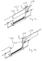
- einen erfindungsgemäßen Sicherungsbausatz 10 mit Schlosseinheit 20 und Schlüsselelement 50,
- Fig. 2b
- den erfindungsgemäßen Sicherungsbausatz aus
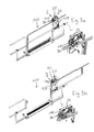
Fig. 2a in einer Freigabestellung, - Fig. 3a
- eine Etagentür 100 mit angebauter Schlosseinheit 20 in der Sicherungsstellung, und
- Fig. 3b
- die Etagentür 100 mit angebauter Schlosseinheit 20 in der Freigabestellung.
- An der Ladestelle eines in den Figuren nicht näher dargestellten Bauwerks kann eine horizontal verschiebbare Etagentür 100 vorgesehen sein, die den Durchgang zwischen der Ladestelle und dem Fahrkorb eines Bauaufzugs verschließt. Das Bauwerk kann eine nicht näher dargestellte Mehrzahl solcher Ladestellen aufweisen, die jeweils von dem mittels eines Antriebs verfahrbaren Fahrkorb angefahren werden. Der Fahrkorb kann verschwenkbar an einem Mast angeordnet sein, so dass er an die Ladestelle angeschwenkt werden kann, sobald er in der korrekten Ladestellenhöhe angeordnet ist. In dieser Stellung ist der Durchgang zwischen dem Fahrkorb und der Plattform des Fahrkorbs noch geschlossen, da eine Klappe des Fahrkorbs noch geschlossen ist und sich auch die Etagentür 100 in der in
Fig. 1a dargestellten geschlossenen und verriegelten Verriegelungsstellung I befindet. Bei der inFig. 1 dargestellten herkömmlichen Etagentür wird die Etagentür 100 durch Verschwenken des Entriegelungshebels 110 der Entriegelungsvorrichtung 108 nach rechts entriegelt und kann dann geöffnet werden (siehe inFig. 1b gezeigte Entriegelungsstellung II mit geöffneter Etagentür). - An die Zargenanordnung 105 der Etagentür 100 bzw. an die herkömmliche Entriegelungsanordnung 108 kann nun die Schlosseinheit 20 des in den
Figuren 2a und 2b dargestellten erfindungsgemäßen Sicherungsbausatzes 10 angebaut werden. Dazu wird das Gehäuse 25 oder ein anderer Befestigungsabschnitt 27 der Schlosseinheit 20 an der Entriegelungsanordnung 108 lösbar bspw. mittels Schrauben o.dgl. befestigt, so dass die Schlosseinheit 20 bei Bedarf wieder von der Etagentür 100 demontiert werden kann. - Bei der Montage der Schlosseinheit 20 wird darauf geachtet, dass das hebelförmige Entriegelungselement 110 der Entriegelungsvorrichtung 108 in eine zwischen einer Sperre 24 und einem Betätigungselement 30 der Schlosseinheit gebildete Öffnung bzw. einen Zwischenraum eingeführt wird, der bspw. durch eine Schlaufe des Betätigungselements 30 gebildet wird.
- Die Schlosseinheit 20 weist ein Schloss 22 auf, in das ein dazu passendes Schlüsselelement 50 einführbar ist (siehe
Fig. 2a ). Wenn das Schlüsselelement 50 nicht in das Schloss 22 eingeführt ist, befindet sich dieses in der Sicherungsstellung (sieheFig. 3a ), in der die Sperre 24 in den Betätigungsweg A des Entriegelungselements 110 eingreift. Eine Betätigung des Entriegelungselements 110 zum Entriegeln der Etagentür ist dann nicht möglich. - Durch das Einführen des Schlüsselelements 50 in das Schloss 22 und das anschließendes Verstellen des Schlosses ist das Schloss in eine Freigabestellung (siehe
Figuren 2b und3b ) verstellbar, wobei die Sperre 24 durch das Verstellen aus dem Betätigungsweg A herausbewegt wird. Bei der dargestellten Ausführungsform wird durch das Verstellen des Schlosses 22 in die Freigabestellung die Sperre 24 um eine Drehachse herum von dem Hebel 110 weggeschwenkt. Gleichzeitig zieht das ausgehend von der Sperre 24 bügelförmig bzw. schlaufenartig vorstehende Betätigungselement 30 das Entriegelungselement 110 in die Entriegelungsstellung II, in der die Etagentür 100 entriegelt ist und geöffnet werden kann. Umgekehrt drückt ein Führungsabschnitt 21 der Sperre 24 bei einem Verstellen des Schlosses 22 zurück in die Sicherungsstellung den Entriegelungshebel 110 zurück in die Verriegelungsstellung I, in der die Etagentür verriegelt ist. - Ein Verstellen des Schlosses bzw. ein Herausziehen des Schlüsselelements aus dem Schloss ist im geöffneten Zustand der Etagentüre nicht möglich. Vielmehr ist eine Rückstellung des Entriegelungselements 110 in die Verriegelungsstellung I erst dann möglich, wenn die Etagentür geschlossen ist. Erst nach dem Verstellen des Schlosses in die Sicherungsstellung kann das Schlüsselelement aus dem Schloss genommen werden.
- Das Schlüsselelement 50 ist bei der in
Fig. 2a dargestellten Ausführungsform als ein Schwenkhebel ausgebildet und mittels eines speziellen Anbringungsmittels 52 wie etwa eines flexiblen Bands oder einer Kette an dem Fahrkorb anbringbar. Das Anbringungsmittel 52 ist einerseits an dem Schlüsselelement 50 befestigt und kann andererseits an einem Gestänge o. dgl. des Fahrkorbs angebracht werden. Von besonderer Bedeutung ist dabei, dass das Anbringungsmittel 52 eine solche Länge aufweist, dass das Schlüsselelement 50 erst nach korrekter Positionierung des Fahrkorbs (nicht gezeigt) an der Ladestelle in Eingriff mit dem Schloss 22 der an der Entriegelungsvorrichtung 108 befestigten Schlosseinheit 20 bringbar ist. - Wenn dann der Fahrkorb des Aufzugs in Bezug auf die Ladestelle korrekt positioniert ist, kann das an dem Fahrkorb befestigte Schlüsselelement 50 in das Schloss 22 eingeführt werden und das Schloss anschließend in die Freigabestellung verstellt werden, in der die Sperre 24 nicht mehr in den Betätigungsweg A des Entriegelungselements 110 eingreift und das Betätigungselement 30 das Entriegelungselement in die Entriegelungsstellung II gezogen hat.
- Zur weiteren Sicherung der Etagentür gegen unerwünschtes Öffnen kann eine zweite Entriegelungsvorrichtung vorgesehen sein, die von dem sich an die Ladestelle bewegenden Fahrkorb oder einer sich öffnenden Fahrkorbklappe automatisch betätigt wird.
- Alternative Ausführungsformen sind ebenfalls vorstellbar. Bspw. weist die Schlosseinheit nicht notwendigerweise ein Betätigungselement, sondern lediglich einen Sperrenabschnitt auf, die in der Sicherungsstellung des Schlosses bspw. von der Seite in den Betätigungsweg des Entriegelungselement eingefahren ist und eine Entriegelung verhindert. Nur in der Freigabestellung ist der Betätigungsweg des Entriegelungselements freigegeben und die Etagentüre händisch entriegelbar.
Claims (15)
- Sicherungsbausatz (10) zum Sichern einer mittels eines handbetätigbaren Entriegelungselements (110) entriegelbaren Aufzugs-Etagentür (100), gekennzeichnet durch
eine in der Umgebung des Entriegelungselements (110) befestigbare Schlosseinheit (20) mit einem Schloss (22) und einer Sperre (24) zum Verhindern der Betätigung des Entriegelungselements (110) in einer Sicherungsstellung des Schlosses (22) und zum Freigeben und/oder Bewirken der Betätigung des Entriegelungselements (110) durch Verstellen des Schlosses (22) von der Sicherungsstellung in eine Freigabestellung,
und ein zu dem Schloss passendes Schlüsselelement (50) zum Verstellen des Schlosses (22). - Sicherungsbausatz nach Anspruch 1, dadurch gekennzeichnet, dass die Sperre (24) zum Eingreifen in einen Betätigungsweg (A) des Entriegelungselements (110) in der Sicherungsstellung des Schlosses (22) eingerichtet ist.
- Sicherungsbausatz nach Anspruch 1 oder 2, dadurch gekennzeichnet, dass die Sperre (24) durch Verstellen des Schlosses (22) in die Freigabestellung aus dem Betätigungsweg (A) des Entriegelungselements (110) herausbewegbar ist.
- Sicherungsbausatz nach einem der vorhergehenden Ansprüche, dadurch gekennzeichnet, dass die Sperre (24) bei dem Verstellen des Schlosses (22) von der Freigabestellung in die Sicherungsstellung in Anlage an das Entriegelungselement (110) kommt und das Entriegelungselement (110) zurück in eine Verriegelungsstellung (I) drängt, in der die Aufzugs-Etagentür (100) verriegelt ist.
- Sicherungsbausatz nach einem der vorhergehenden Ansprüche, dadurch gekennzeichnet, dass die Schlosseinheit (10) ein Betätigungselement (30) zum Betätigen des Entriegelungselements (110) durch Verstellen des Schlosses (22) aufweist.
- Sicherungsbausatz nach Anspruch 5, dadurch gekennzeichnet, dass das Betätigungselement (30) derart eingerichtet ist, dass es bei einem Verstellen des Schlosses (22) von der Sicherungsstellung in die Freigabestellung das Entriegelungselement (110) betätigt, so dass die Aufzugs-Etagentür (100) entriegelt wird.
- Sicherungsbausatz nach Anspruch 5 oder 6, dadurch gekennzeichnet, dass das Betätigungselement (30) mit der Sperre (24) verbunden und zusammen mit der Sperre beweglich ist.
- Sicherungsbausatz nach einem der Ansprüche 5 bis 7, dadurch gekennzeichnet, dass das Betätigungselement (30) ein Schlaufenelement oder einen Ausleger zum Übergreifen oder Umgreifen des Entriegelungselements (110) ausgehend von der Sperre aufweist.
- Sicherungsbausatz nach einem der vorhergehenden Ansprüche, dadurch gekennzeichnet, dass das Schlüsselelement (50) ein flexibles Anbringungsmittel (52) wie etwa eine Kette oder ein Band zum Anbringen an einem Fahrkorb eines Aufzugs aufweist und/oder dass die Schlosseinheit (20) mittels eines Befestigungsmittels lösbar an der Aufzugs-Etagentür (100), einer Zargenanordnung (105) der Aufzugs-Etagentür (100) und/oder einer daran angeordneten Entriegelungsvorrichtung (108), die das Entriegelungselement (110) aufweist, anbringbar ist.
- Sicherungsbausatz nach einem der vorhergehenden Ansprüche, dadurch gekennzeichnet, dass die Schlosseinheit (20) eine Abdeckung oder ein Gehäuse (25) aufweist, das das Entriegelungselement (110) zumindest teilweise abdeckt.
- Aufzug mit einem Fahrkorb und einer Aufzugs-Etagentür (100), die einen Durchgang zwischen dem Fahrkorb und einer dadurch anfahrbaren Ladestelle sichert, gekennzeichnet durch einen Sicherungsbausatz (10) nach einem der vorhergehenden Ansprüche, dessen Schlüsselelement (50) und dessen Schlosseinheit (20) voneinander getrennt einerseits an dem Fahrkorb und andererseits an der Aufzugs-Etagentür oder deren Zargenanordnung befestigt sind, so dass sie erst bei korrekt an der Ladestelle positioniertem Fahrkorb zum Verstellen des Schlosses zum Entriegeln oder Verriegeln der Etagentür miteinander in Eingriff bringbar sind.
- Aufzug nach Anspruch 11, gekennzeichnet durch eine an der Zargenanordnung (105) der Aufzugs-Etagentür angebrachte Entriegelungsvorrichtung (108) mit dem Entriegelungselement (110) in Form eines Handbetätigers wie etwa eines Handhebels, Handgriffs, Knopfs o. dgl. zum Entriegeln der Etagentür, dessen Betätigung durch die Sperre (24) der Schlosseinheit in der Sicherungsstellung des Schlosses (22) verhindert wird und dessen Betätigung durch Verstellen des Schlosses in die Freigabestellung freigegeben wird.
- Aufzug nach Anspruch 10 oder 11, dadurch gekennzeichnet, dass das Schlüsselelement (50) mittels eines flexiblen Anbringungsmittels (52) wie etwa eines Bands oder einer Kette an dem Fahrkorb befestigt ist und/oder die Schlosseinheit (20) mittels eines Befestigungsmittels wie etwa Schrauben an der Zargenanordnung (105) der Etagentür und/oder der daran angebrachten Entriegelungsvorrichtung (108) befestigt ist.
- Aufzug nach einem der Ansprüche 10 bis 13, dadurch gekennzeichnet, dass die Sperre (24) der Schlosseinheit bei einer Verstellung des Schlosses in die Sicherungsstellung in Anlage an das Entriegelungselement (110) kommt und dieses zum Verriegeln der Aufzugs-Etagentür betätigt und/oder dass das Betätigungselement (30) bei einer Verstellung des Schlosses in die Freigabestellung in Anlage an das Entriegelungselement (110) kommt und dieses zum Entriegeln der Aufzugs-Etagentür betätigt.
- Aufzug nach einem der Ansprüche 10 bis 14, dadurch gekennzeichnet, dass das Entriegelungselement (110) ein verschwenkbarer Handhebel ist, auf dessen einer Seite die Sperre (24) angeordnet ist, von der ausgehend das schlaufenförmige Betätigungselement den Handhebel umläuft oder übergreift.
Applications Claiming Priority (1)
| Application Number | Priority Date | Filing Date | Title |
|---|---|---|---|
| DE202014005765.6U DE202014005765U1 (de) | 2014-07-15 | 2014-07-15 | Sicherungsbausatz für eine Aufzugs-Etagentür |
Publications (2)
| Publication Number | Publication Date |
|---|---|
| EP2974989A1 true EP2974989A1 (de) | 2016-01-20 |
| EP2974989B1 EP2974989B1 (de) | 2022-02-23 |
Family
ID=51353348
Family Applications (1)
| Application Number | Title | Priority Date | Filing Date |
|---|---|---|---|
| EP15002038.6A Active EP2974989B1 (de) | 2014-07-15 | 2015-07-07 | Sicherungsbausatz für eine aufzugs-etagentür |
Country Status (2)
| Country | Link |
|---|---|
| EP (1) | EP2974989B1 (de) |
| DE (1) | DE202014005765U1 (de) |
Cited By (2)
| Publication number | Priority date | Publication date | Assignee | Title |
|---|---|---|---|---|
| DE202016101903U1 (de) | 2016-04-11 | 2017-07-12 | Geda-Dechentreiter Gmbh & Co. Kg | Absturzsicherung am Übergang zu einem Gebäude oder Gerüst eines Aufzugs |
| EP3483110A1 (de) * | 2017-11-08 | 2019-05-15 | Otis Elevator Company | Aufzugszugangssysteme für aufzüge |
Families Citing this family (1)
| Publication number | Priority date | Publication date | Assignee | Title |
|---|---|---|---|---|
| EP4644639A1 (de) | 2024-05-03 | 2025-11-05 | GEDA GmbH | Gerüsthaltestellensicherungsschranke und gerüst |
Citations (6)
| Publication number | Priority date | Publication date | Assignee | Title |
|---|---|---|---|---|
| US596169A (en) * | 1897-12-28 | ladewich | ||
| US1753664A (en) * | 1924-12-12 | 1930-04-08 | Peelle Co The | Center lock for counterbalanced elevator doors |
| US3298210A (en) * | 1964-12-29 | 1967-01-17 | Elevator Specialties Corp | Elevator shaft door safety mechanism |
| FR2821613A1 (fr) | 2001-03-05 | 2002-09-06 | Xavier Lombard | Verrouillage de porte-paliere d'ascenseur |
| DE202009014346U1 (de) | 2009-10-23 | 2009-12-24 | Geda-Dechentreiter Gmbh & Co. Kg | Verriegelungsvorrichtung |
| DE102010015476A1 (de) * | 2010-04-16 | 2011-10-20 | Böcker AG | Verriegelungsvorrichtung für ein Ladestellentor |
-
2014
- 2014-07-15 DE DE202014005765.6U patent/DE202014005765U1/de not_active Expired - Lifetime
-
2015
- 2015-07-07 EP EP15002038.6A patent/EP2974989B1/de active Active
Patent Citations (6)
| Publication number | Priority date | Publication date | Assignee | Title |
|---|---|---|---|---|
| US596169A (en) * | 1897-12-28 | ladewich | ||
| US1753664A (en) * | 1924-12-12 | 1930-04-08 | Peelle Co The | Center lock for counterbalanced elevator doors |
| US3298210A (en) * | 1964-12-29 | 1967-01-17 | Elevator Specialties Corp | Elevator shaft door safety mechanism |
| FR2821613A1 (fr) | 2001-03-05 | 2002-09-06 | Xavier Lombard | Verrouillage de porte-paliere d'ascenseur |
| DE202009014346U1 (de) | 2009-10-23 | 2009-12-24 | Geda-Dechentreiter Gmbh & Co. Kg | Verriegelungsvorrichtung |
| DE102010015476A1 (de) * | 2010-04-16 | 2011-10-20 | Böcker AG | Verriegelungsvorrichtung für ein Ladestellentor |
Cited By (6)
| Publication number | Priority date | Publication date | Assignee | Title |
|---|---|---|---|---|
| DE202016101903U1 (de) | 2016-04-11 | 2017-07-12 | Geda-Dechentreiter Gmbh & Co. Kg | Absturzsicherung am Übergang zu einem Gebäude oder Gerüst eines Aufzugs |
| EP3231960A1 (de) | 2016-04-11 | 2017-10-18 | GEDA-Dechentreiter GmbH & Co. KG. | Absturzsicherung am übergang zu einem gebäude oder gerüst eines aufzugs |
| EP3483110A1 (de) * | 2017-11-08 | 2019-05-15 | Otis Elevator Company | Aufzugszugangssysteme für aufzüge |
| CN109896367A (zh) * | 2017-11-08 | 2019-06-18 | 奥的斯电梯公司 | 用于电梯的电梯访问系统 |
| CN109896367B (zh) * | 2017-11-08 | 2021-05-04 | 奥的斯电梯公司 | 用于电梯的电梯访问系统 |
| US11124385B2 (en) | 2017-11-08 | 2021-09-21 | Otis Elevator Company | Elevator access systems for elevators |
Also Published As
| Publication number | Publication date |
|---|---|
| EP2974989B1 (de) | 2022-02-23 |
| DE202014005765U1 (de) | 2014-07-28 |
Similar Documents
| Publication | Publication Date | Title |
|---|---|---|
| EP1178171B1 (de) | Kraftfahrzeugtürverschluss | |
| DE102006059565B4 (de) | Schließanlage für Türen, Fenster oder dergleichen, insbesondere Treibstangenschloss mit Panikfunktion und Mehrpunktverriegelung | |
| EP2974989B1 (de) | Sicherungsbausatz für eine aufzugs-etagentür | |
| DE102017208059A1 (de) | Fenster oder Tür mit einbruchsicherer Kippöffnungsbegrenzung | |
| DE19955693C2 (de) | Kraftfahrzeugtürverschluss | |
| EP2677098B1 (de) | Schliessvorrichtung mit Notöffnung | |
| DE102012111881A1 (de) | Motorisch betreibbares Standflügelschloss mit Riegel- und Fallenauswerfer | |
| EP2746496B1 (de) | Sicherungsvorrichtung für einen fenster- oder türgriff | |
| DE29619007U1 (de) | Verriegelungsvorrichtung | |
| DE3604083A1 (de) | Feststellvorrichtung fuer tuerfluegel mit einem tuerschliesser | |
| EP3805493B1 (de) | Modular aufgebautes schloss mit panikfunktion | |
| EP0678639A1 (de) | Verriegelung für Schiebeläden, Schiebetüren und dgl. entlang einer feststehenden Schiene verfahrbare Elemente | |
| DE102010041913A1 (de) | Entriegelungsvorrichtung | |
| EP1418296B1 (de) | Gesicherte Notentriegelungsvorrichtung sowie Verwendung derselben | |
| AT392819B (de) | Schloss, insbesondere panikschloss | |
| AT395630B (de) | Doppelfluegelige brandschutztuer | |
| EP3822437B1 (de) | Tür oder fenstersystem | |
| EP1970508A2 (de) | Vorrichtung zur Arretierung eines schwenkbaren Bauteiles eines Kraftfahrzeuges | |
| DE202008004659U1 (de) | Öffnungsbegrenzung für ein Fenster oder eine Tür | |
| DE10015095C2 (de) | Verriegelungsvorrichtung für einen Türflügel | |
| DE3345814A1 (de) | Vorrichtung zur selbsttaetigen fehlbedienungssicherung einer an einem fenster- od.dgl. -fluegel vorgesehenen stellstange | |
| DE60104698T2 (de) | Endverschlusskappe für einen Rolladenkasten | |
| EP3655601B1 (de) | Schloss | |
| DE8312253U1 (de) | Vorrichtung zur selbsttaetigen fehlbedienungssicherung einer an einem fenster- od.dgl. -fluegel vorgesehenen stellstange | |
| DE4036878C2 (de) | Drehkreuzanlage für die Zugangskontrolle zu einem gesicherten Gebiet oder Gebäude |
Legal Events
| Date | Code | Title | Description |
|---|---|---|---|
| PUAI | Public reference made under article 153(3) epc to a published international application that has entered the european phase |
Free format text: ORIGINAL CODE: 0009012 |
|
| AK | Designated contracting states |
Kind code of ref document: A1 Designated state(s): AL AT BE BG CH CY CZ DE DK EE ES FI FR GB GR HR HU IE IS IT LI LT LU LV MC MK MT NL NO PL PT RO RS SE SI SK SM TR |
|
| AX | Request for extension of the european patent |
Extension state: BA ME |
|
| 17P | Request for examination filed |
Effective date: 20160719 |
|
| RBV | Designated contracting states (corrected) |
Designated state(s): AL AT BE BG CH CY CZ DE DK EE ES FI FR GB GR HR HU IE IS IT LI LT LU LV MC MK MT NL NO PL PT RO RS SE SI SK SM TR |
|
| RAP1 | Party data changed (applicant data changed or rights of an application transferred) |
Owner name: GEDA GMBH |
|
| STAA | Information on the status of an ep patent application or granted ep patent |
Free format text: STATUS: EXAMINATION IS IN PROGRESS |
|
| 17Q | First examination report despatched |
Effective date: 20210616 |
|
| GRAP | Despatch of communication of intention to grant a patent |
Free format text: ORIGINAL CODE: EPIDOSNIGR1 |
|
| STAA | Information on the status of an ep patent application or granted ep patent |
Free format text: STATUS: GRANT OF PATENT IS INTENDED |
|
| INTG | Intention to grant announced |
Effective date: 20211025 |
|
| GRAS | Grant fee paid |
Free format text: ORIGINAL CODE: EPIDOSNIGR3 |
|
| GRAA | (expected) grant |
Free format text: ORIGINAL CODE: 0009210 |
|
| STAA | Information on the status of an ep patent application or granted ep patent |
Free format text: STATUS: THE PATENT HAS BEEN GRANTED |
|
| AK | Designated contracting states |
Kind code of ref document: B1 Designated state(s): AL AT BE BG CH CY CZ DE DK EE ES FI FR GB GR HR HU IE IS IT LI LT LU LV MC MK MT NL NO PL PT RO RS SE SI SK SM TR |
|
| REG | Reference to a national code |
Ref country code: GB Ref legal event code: FG4D Free format text: NOT ENGLISH |
|
| REG | Reference to a national code |
Ref country code: CH Ref legal event code: EP |
|
| REG | Reference to a national code |
Ref country code: AT Ref legal event code: REF Ref document number: 1470323 Country of ref document: AT Kind code of ref document: T Effective date: 20220315 |
|
| REG | Reference to a national code |
Ref country code: IE Ref legal event code: FG4D Free format text: LANGUAGE OF EP DOCUMENT: GERMAN |
|
| REG | Reference to a national code |
Ref country code: DE Ref legal event code: R096 Ref document number: 502015015641 Country of ref document: DE |
|
| REG | Reference to a national code |
Ref country code: LT Ref legal event code: MG9D |
|
| REG | Reference to a national code |
Ref country code: NL Ref legal event code: MP Effective date: 20220223 |
|
| PG25 | Lapsed in a contracting state [announced via postgrant information from national office to epo] |
Ref country code: SE Free format text: LAPSE BECAUSE OF FAILURE TO SUBMIT A TRANSLATION OF THE DESCRIPTION OR TO PAY THE FEE WITHIN THE PRESCRIBED TIME-LIMIT Effective date: 20220223 Ref country code: RS Free format text: LAPSE BECAUSE OF FAILURE TO SUBMIT A TRANSLATION OF THE DESCRIPTION OR TO PAY THE FEE WITHIN THE PRESCRIBED TIME-LIMIT Effective date: 20220223 Ref country code: PT Free format text: LAPSE BECAUSE OF FAILURE TO SUBMIT A TRANSLATION OF THE DESCRIPTION OR TO PAY THE FEE WITHIN THE PRESCRIBED TIME-LIMIT Effective date: 20220623 Ref country code: NO Free format text: LAPSE BECAUSE OF FAILURE TO SUBMIT A TRANSLATION OF THE DESCRIPTION OR TO PAY THE FEE WITHIN THE PRESCRIBED TIME-LIMIT Effective date: 20220523 Ref country code: NL Free format text: LAPSE BECAUSE OF FAILURE TO SUBMIT A TRANSLATION OF THE DESCRIPTION OR TO PAY THE FEE WITHIN THE PRESCRIBED TIME-LIMIT Effective date: 20220223 Ref country code: LT Free format text: LAPSE BECAUSE OF FAILURE TO SUBMIT A TRANSLATION OF THE DESCRIPTION OR TO PAY THE FEE WITHIN THE PRESCRIBED TIME-LIMIT Effective date: 20220223 Ref country code: HR Free format text: LAPSE BECAUSE OF FAILURE TO SUBMIT A TRANSLATION OF THE DESCRIPTION OR TO PAY THE FEE WITHIN THE PRESCRIBED TIME-LIMIT Effective date: 20220223 Ref country code: ES Free format text: LAPSE BECAUSE OF FAILURE TO SUBMIT A TRANSLATION OF THE DESCRIPTION OR TO PAY THE FEE WITHIN THE PRESCRIBED TIME-LIMIT Effective date: 20220223 Ref country code: BG Free format text: LAPSE BECAUSE OF FAILURE TO SUBMIT A TRANSLATION OF THE DESCRIPTION OR TO PAY THE FEE WITHIN THE PRESCRIBED TIME-LIMIT Effective date: 20220523 |
|
| PG25 | Lapsed in a contracting state [announced via postgrant information from national office to epo] |
Ref country code: PL Free format text: LAPSE BECAUSE OF FAILURE TO SUBMIT A TRANSLATION OF THE DESCRIPTION OR TO PAY THE FEE WITHIN THE PRESCRIBED TIME-LIMIT Effective date: 20220223 Ref country code: LV Free format text: LAPSE BECAUSE OF FAILURE TO SUBMIT A TRANSLATION OF THE DESCRIPTION OR TO PAY THE FEE WITHIN THE PRESCRIBED TIME-LIMIT Effective date: 20220223 Ref country code: GR Free format text: LAPSE BECAUSE OF FAILURE TO SUBMIT A TRANSLATION OF THE DESCRIPTION OR TO PAY THE FEE WITHIN THE PRESCRIBED TIME-LIMIT Effective date: 20220524 Ref country code: FI Free format text: LAPSE BECAUSE OF FAILURE TO SUBMIT A TRANSLATION OF THE DESCRIPTION OR TO PAY THE FEE WITHIN THE PRESCRIBED TIME-LIMIT Effective date: 20220223 |
|
| PG25 | Lapsed in a contracting state [announced via postgrant information from national office to epo] |
Ref country code: IS Free format text: LAPSE BECAUSE OF FAILURE TO SUBMIT A TRANSLATION OF THE DESCRIPTION OR TO PAY THE FEE WITHIN THE PRESCRIBED TIME-LIMIT Effective date: 20220623 |
|
| PG25 | Lapsed in a contracting state [announced via postgrant information from national office to epo] |
Ref country code: SM Free format text: LAPSE BECAUSE OF FAILURE TO SUBMIT A TRANSLATION OF THE DESCRIPTION OR TO PAY THE FEE WITHIN THE PRESCRIBED TIME-LIMIT Effective date: 20220223 Ref country code: SK Free format text: LAPSE BECAUSE OF FAILURE TO SUBMIT A TRANSLATION OF THE DESCRIPTION OR TO PAY THE FEE WITHIN THE PRESCRIBED TIME-LIMIT Effective date: 20220223 Ref country code: RO Free format text: LAPSE BECAUSE OF FAILURE TO SUBMIT A TRANSLATION OF THE DESCRIPTION OR TO PAY THE FEE WITHIN THE PRESCRIBED TIME-LIMIT Effective date: 20220223 Ref country code: EE Free format text: LAPSE BECAUSE OF FAILURE TO SUBMIT A TRANSLATION OF THE DESCRIPTION OR TO PAY THE FEE WITHIN THE PRESCRIBED TIME-LIMIT Effective date: 20220223 Ref country code: DK Free format text: LAPSE BECAUSE OF FAILURE TO SUBMIT A TRANSLATION OF THE DESCRIPTION OR TO PAY THE FEE WITHIN THE PRESCRIBED TIME-LIMIT Effective date: 20220223 Ref country code: CZ Free format text: LAPSE BECAUSE OF FAILURE TO SUBMIT A TRANSLATION OF THE DESCRIPTION OR TO PAY THE FEE WITHIN THE PRESCRIBED TIME-LIMIT Effective date: 20220223 |
|
| REG | Reference to a national code |
Ref country code: DE Ref legal event code: R097 Ref document number: 502015015641 Country of ref document: DE |
|
| PG25 | Lapsed in a contracting state [announced via postgrant information from national office to epo] |
Ref country code: AL Free format text: LAPSE BECAUSE OF FAILURE TO SUBMIT A TRANSLATION OF THE DESCRIPTION OR TO PAY THE FEE WITHIN THE PRESCRIBED TIME-LIMIT Effective date: 20220223 |
|
| PLBE | No opposition filed within time limit |
Free format text: ORIGINAL CODE: 0009261 |
|
| STAA | Information on the status of an ep patent application or granted ep patent |
Free format text: STATUS: NO OPPOSITION FILED WITHIN TIME LIMIT |
|
| 26N | No opposition filed |
Effective date: 20221124 |
|
| PG25 | Lapsed in a contracting state [announced via postgrant information from national office to epo] |
Ref country code: SI Free format text: LAPSE BECAUSE OF FAILURE TO SUBMIT A TRANSLATION OF THE DESCRIPTION OR TO PAY THE FEE WITHIN THE PRESCRIBED TIME-LIMIT Effective date: 20220223 Ref country code: MC Free format text: LAPSE BECAUSE OF FAILURE TO SUBMIT A TRANSLATION OF THE DESCRIPTION OR TO PAY THE FEE WITHIN THE PRESCRIBED TIME-LIMIT Effective date: 20220223 |
|
| REG | Reference to a national code |
Ref country code: CH Ref legal event code: PL |
|
| REG | Reference to a national code |
Ref country code: BE Ref legal event code: MM Effective date: 20220731 |
|
| PG25 | Lapsed in a contracting state [announced via postgrant information from national office to epo] |
Ref country code: LU Free format text: LAPSE BECAUSE OF NON-PAYMENT OF DUE FEES Effective date: 20220707 Ref country code: LI Free format text: LAPSE BECAUSE OF NON-PAYMENT OF DUE FEES Effective date: 20220731 Ref country code: CH Free format text: LAPSE BECAUSE OF NON-PAYMENT OF DUE FEES Effective date: 20220731 |
|
| PG25 | Lapsed in a contracting state [announced via postgrant information from national office to epo] |
Ref country code: BE Free format text: LAPSE BECAUSE OF NON-PAYMENT OF DUE FEES Effective date: 20220731 |
|
| PG25 | Lapsed in a contracting state [announced via postgrant information from national office to epo] |
Ref country code: IT Free format text: LAPSE BECAUSE OF FAILURE TO SUBMIT A TRANSLATION OF THE DESCRIPTION OR TO PAY THE FEE WITHIN THE PRESCRIBED TIME-LIMIT Effective date: 20220223 Ref country code: IE Free format text: LAPSE BECAUSE OF NON-PAYMENT OF DUE FEES Effective date: 20220707 |
|
| REG | Reference to a national code |
Ref country code: AT Ref legal event code: MM01 Ref document number: 1470323 Country of ref document: AT Kind code of ref document: T Effective date: 20220707 |
|
| PG25 | Lapsed in a contracting state [announced via postgrant information from national office to epo] |
Ref country code: AT Free format text: LAPSE BECAUSE OF NON-PAYMENT OF DUE FEES Effective date: 20220707 |
|
| REG | Reference to a national code |
Ref country code: DE Ref legal event code: R082 Ref document number: 502015015641 Country of ref document: DE Representative=s name: KANDLBINDER, MARKUS, DIPL.-PHYS., DE |
|
| PG25 | Lapsed in a contracting state [announced via postgrant information from national office to epo] |
Ref country code: HU Free format text: LAPSE BECAUSE OF FAILURE TO SUBMIT A TRANSLATION OF THE DESCRIPTION OR TO PAY THE FEE WITHIN THE PRESCRIBED TIME-LIMIT; INVALID AB INITIO Effective date: 20150707 |
|
| PG25 | Lapsed in a contracting state [announced via postgrant information from national office to epo] |
Ref country code: MK Free format text: LAPSE BECAUSE OF FAILURE TO SUBMIT A TRANSLATION OF THE DESCRIPTION OR TO PAY THE FEE WITHIN THE PRESCRIBED TIME-LIMIT Effective date: 20220223 Ref country code: CY Free format text: LAPSE BECAUSE OF FAILURE TO SUBMIT A TRANSLATION OF THE DESCRIPTION OR TO PAY THE FEE WITHIN THE PRESCRIBED TIME-LIMIT Effective date: 20220223 |
|
| PG25 | Lapsed in a contracting state [announced via postgrant information from national office to epo] |
Ref country code: MT Free format text: LAPSE BECAUSE OF FAILURE TO SUBMIT A TRANSLATION OF THE DESCRIPTION OR TO PAY THE FEE WITHIN THE PRESCRIBED TIME-LIMIT Effective date: 20220223 |
|
| PGFP | Annual fee paid to national office [announced via postgrant information from national office to epo] |
Ref country code: DE Payment date: 20250925 Year of fee payment: 11 |
|
| PGFP | Annual fee paid to national office [announced via postgrant information from national office to epo] |
Ref country code: GB Payment date: 20250724 Year of fee payment: 11 |
|
| PGFP | Annual fee paid to national office [announced via postgrant information from national office to epo] |
Ref country code: FR Payment date: 20250723 Year of fee payment: 11 |
|
| PG25 | Lapsed in a contracting state [announced via postgrant information from national office to epo] |
Ref country code: TR Free format text: LAPSE BECAUSE OF FAILURE TO SUBMIT A TRANSLATION OF THE DESCRIPTION OR TO PAY THE FEE WITHIN THE PRESCRIBED TIME-LIMIT Effective date: 20220223 |