EP2975621A1 - Kondensatorbank - Google Patents
Kondensatorbank Download PDFInfo
- Publication number
- EP2975621A1 EP2975621A1 EP14177114.7A EP14177114A EP2975621A1 EP 2975621 A1 EP2975621 A1 EP 2975621A1 EP 14177114 A EP14177114 A EP 14177114A EP 2975621 A1 EP2975621 A1 EP 2975621A1
- Authority
- EP
- European Patent Office
- Prior art keywords
- capacitors
- capacitor bank
- resistors
- capacitor
- series
- Prior art date
- Legal status (The legal status is an assumption and is not a legal conclusion. Google has not performed a legal analysis and makes no representation as to the accuracy of the status listed.)
- Withdrawn
Links
Images

Classifications
-
- H—ELECTRICITY
- H02—GENERATION; CONVERSION OR DISTRIBUTION OF ELECTRIC POWER
- H02M—APPARATUS FOR CONVERSION BETWEEN AC AND AC, BETWEEN AC AND DC, OR BETWEEN DC AND DC, AND FOR USE WITH MAINS OR SIMILAR POWER SUPPLY SYSTEMS; CONVERSION OF DC OR AC INPUT POWER INTO SURGE OUTPUT POWER; CONTROL OR REGULATION THEREOF
- H02M5/00—Conversion of AC power input into AC power output, e.g. for change of voltage, for change of frequency, for change of number of phases
- H02M5/40—Conversion of AC power input into AC power output, e.g. for change of voltage, for change of frequency, for change of number of phases with intermediate conversion into DC
- H02M5/42—Conversion of AC power input into AC power output, e.g. for change of voltage, for change of frequency, for change of number of phases with intermediate conversion into DC by static converters
- H02M5/44—Conversion of AC power input into AC power output, e.g. for change of voltage, for change of frequency, for change of number of phases with intermediate conversion into DC by static converters using discharge tubes or semiconductor devices to convert the intermediate DC into AC
- H02M5/453—Conversion of AC power input into AC power output, e.g. for change of voltage, for change of frequency, for change of number of phases with intermediate conversion into DC by static converters using discharge tubes or semiconductor devices to convert the intermediate DC into AC using devices of a triode or transistor type requiring continuous application of a control signal
- H02M5/458—Conversion of AC power input into AC power output, e.g. for change of voltage, for change of frequency, for change of number of phases with intermediate conversion into DC by static converters using discharge tubes or semiconductor devices to convert the intermediate DC into AC using devices of a triode or transistor type requiring continuous application of a control signal using semiconductor devices only
-
- H—ELECTRICITY
- H01—ELECTRIC ELEMENTS
- H01G—CAPACITORS; CAPACITORS, RECTIFIERS, DETECTORS, SWITCHING DEVICES, LIGHT-SENSITIVE OR TEMPERATURE-SENSITIVE DEVICES OF THE ELECTROLYTIC TYPE
- H01G4/00—Fixed capacitors; Processes of their manufacture
- H01G4/38—Multiple capacitors, i.e. structural combinations of fixed capacitors
-
- H—ELECTRICITY
- H01—ELECTRIC ELEMENTS
- H01G—CAPACITORS; CAPACITORS, RECTIFIERS, DETECTORS, SWITCHING DEVICES, LIGHT-SENSITIVE OR TEMPERATURE-SENSITIVE DEVICES OF THE ELECTROLYTIC TYPE
- H01G4/00—Fixed capacitors; Processes of their manufacture
- H01G4/40—Structural combinations of fixed capacitors with other electric elements, the structure mainly consisting of a capacitor, e.g. RC combinations
-
- H—ELECTRICITY
- H02—GENERATION; CONVERSION OR DISTRIBUTION OF ELECTRIC POWER
- H02J—ELECTRIC POWER NETWORKS; CIRCUIT ARRANGEMENTS OR SYSTEMS FOR SUPPLYING OR DISTRIBUTING ELECTRIC POWER; SYSTEMS FOR STORING ELECTRIC ENERGY
- H02J7/00—Circuit arrangements for charging or discharging batteries or for supplying loads from batteries
- H02J7/34—Parallel operation in networks using both storage and other DC sources, e.g. providing buffering
- H02J7/345—Parallel operation in networks using both storage and other DC sources, e.g. providing buffering using capacitors as storage or buffering devices
-
- H—ELECTRICITY
- H02—GENERATION; CONVERSION OR DISTRIBUTION OF ELECTRIC POWER
- H02P—CONTROL OR REGULATION OF ELECTRIC MOTORS, ELECTRIC GENERATORS OR DYNAMO-ELECTRIC CONVERTERS; CONTROLLING TRANSFORMERS, REACTORS OR CHOKE COILS
- H02P27/00—Arrangements or methods for the control of AC motors characterised by the kind of supply voltage
- H02P27/04—Arrangements or methods for the control of AC motors characterised by the kind of supply voltage using variable-frequency supply voltage, e.g. inverter or converter supply voltage
-
- H—ELECTRICITY
- H01—ELECTRIC ELEMENTS
- H01G—CAPACITORS; CAPACITORS, RECTIFIERS, DETECTORS, SWITCHING DEVICES, LIGHT-SENSITIVE OR TEMPERATURE-SENSITIVE DEVICES OF THE ELECTROLYTIC TYPE
- H01G4/00—Fixed capacitors; Processes of their manufacture
- H01G4/33—Thin- or thick-film capacitors (thin- or thick-film circuits; capacitors without a potential-jump or surface barrier specially adapted for integrated circuits, details thereof, multistep manufacturing processes therefor)
-
- H—ELECTRICITY
- H02—GENERATION; CONVERSION OR DISTRIBUTION OF ELECTRIC POWER
- H02H—EMERGENCY PROTECTIVE CIRCUIT ARRANGEMENTS
- H02H7/00—Emergency protective circuit arrangements specially adapted for specific types of electric machines or apparatus or for sectionalised protection of cable or line systems, and effecting automatic switching in the event of an undesired change from normal working conditions
- H02H7/16—Emergency protective circuit arrangements specially adapted for specific types of electric machines or apparatus or for sectionalised protection of cable or line systems, and effecting automatic switching in the event of an undesired change from normal working conditions for capacitors
-
- H—ELECTRICITY
- H02—GENERATION; CONVERSION OR DISTRIBUTION OF ELECTRIC POWER
- H02H—EMERGENCY PROTECTIVE CIRCUIT ARRANGEMENTS
- H02H9/00—Emergency protective circuit arrangements for limiting excess current or voltage without disconnection
- H02H9/02—Emergency protective circuit arrangements for limiting excess current or voltage without disconnection responsive to excess current
-
- H—ELECTRICITY
- H02—GENERATION; CONVERSION OR DISTRIBUTION OF ELECTRIC POWER
- H02J—ELECTRIC POWER NETWORKS; CIRCUIT ARRANGEMENTS OR SYSTEMS FOR SUPPLYING OR DISTRIBUTING ELECTRIC POWER; SYSTEMS FOR STORING ELECTRIC ENERGY
- H02J7/00—Circuit arrangements for charging or discharging batteries or for supplying loads from batteries
- H02J7/50—Circuit arrangements for charging or discharging batteries or for supplying loads from batteries acting upon multiple batteries simultaneously or sequentially
- H02J7/585—Sequential battery discharge in systems with a plurality of batteries
Definitions
- the present invention relates to capacitor banks.
- the present invention relates also to a subsea electrical component including a capacitor bank for energy storage.
- Subsea equipment are traditionally made by putting electrical and/or electronic components designed for atmospheric pressure into a canister at 1 atm of pressure, in order to protect them from the high ambient subsea pressure.
- electrolytic capacitors are one of those components that need to be inserted in the atmospheric pressure canisters described above, as these capacitors cannot withstand higher pressure.
- An alternative to electrolytic capacitors is that of using film capacitors or ceramic capacitors. The use of film capacitors or ceramic capacitors may be more critical than electrolytic capacitors, as these capacitors normally have a lower capacitance, i.e. a greater number of them have to be used to obtain the same overall capacitance.
- the storage may consist or some or a huge amount of parallel connected capacitor components. No other electrical components are normally inserted in series with the capacitors, for not affecting the current value, when discharge of the capacitor bank is requested.
- one of the capacitors has a failure, for example a short circuit, it may happen that current flows through it, thus shorting the overall storage capacity of the capacitor bank. This may cause also other failures and therefore affects the reliability and lifetime of the whole system. This is of particular importance in subsea systems, which can be accessed with difficulty or with high costs after they have been put in operation.
- a capacitor bank comprises:
- the resistors prevent the whole capacitor bank to be affected by a short circuit in a single capacitor either by just limiting the current or by fusing if the current value is too high.
- the capacitor bank comprises a lot of parallel connections where a plurality of serial resistors is used for limiting the current into a shorted capacitor. This prevents the shorted capacitor from damaging the operation of the whole system. Further, the resistors prevent high inrush current values at power up.
- the present invention may be adapted to a great number of different configurations of capacitor banks, provided that, in each configuration, each resistor is connected in series with one capacitor or with group of capacitors connected in parallel or in series with one another.
- each of the resistors is series with one of the capacitors, each pair of resistor and capacitor being connected in parallel with the other pairs.
- the plurality of capacitors are divided in a plurality of groups of capacitors, the capacitors in each group being electrically connected with one another in series or parallel, each of the resistors being in series with one of the groups of capacitors.
- the capacitors are electrically connected in parallel.
- the capacitor bank further comprises a third plurality of diodes, each of the diodes being in parallel with one of the resistors.
- the resistors increase the overall resistance and voltage drop in each circuit branch including one or more capacitors. This could affect, when requested during normal operations, the current value during discharging of capacitor bank.
- the resistors are paralleled by a diode to reduce the voltage drop at discharging.
- a subsea electrical component comprises a circuit including at least one capacitor bank for direct current (DC) storage according to the present invention.
- This invention gives us the opportunity to an effective way of introducing redundancy to make a DC storage component with very high reliability.
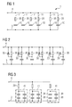
- Figs. 1 to Figs. 6 show possible embodiments of a capacitor bank 1, according to the present invention.
- the capacitor bank 1 is for use as local energy storage for bridging a short power supply blackout (up to some seconds).
- the capacitor bank 1 includes a plurality of capacitors 10 between a first conductor 3 and a second conductor 4 between which an electric potential is subject to be established.
- the capacitor bank 1 further includes a second plurality of resistors 20, each of the capacitors 10 being in series with at least one of the resistors 20.
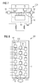
- the capacitor bank 1 is used as direct current storage component in power cell 100 for subsea applications.
- the power cell 100 comprises a casing 50 of metal, such as carbon steel or stainless steel or aluminium.
- the power cell 100 comprises a circuit 60 for converting an electrical three phase input 61 into an electrical one phase output 62.
- the circuit 60 comprises:
- the capacitor bank 1 enables continuous operation of the power cell 100.
- the first conductor 3 and a second conductor 4 of the capacitor bank 1 are connected to the diode rectifier 70 and the plurality of transistors 75 by means of an H-bridge configuration.
- the diode rectifier 70 and the plurality of Insulated Gate Bipolar Transistors 75 are mounted on the same side of the casing 50 in thermal contact with an heat sink 80, for promoting a thermal flow from the circuit 13 to the outside of the casing 50.
- an electrical variable frequency drive 200 comprises a plurality of power cells 100.
- the electrical drive 200 is usable in subsea implementations for providing a three phase electrical alimentation to an electrical motor M.
- the electrical drive 200 comprises an enclosure 201 where a plurality of power cells 100 (eighteen power cells 100) are housed, immersed in a dielectric fluid 250, which is in contact with each power cell 100 for heat loss removal.
- the plurality of power cells 100 are divided in six groups (six power cells for each group). In each group all the power cells 100 are connected to a common output conductor 210, 211, 212, respectively.
- the three output conductor 210, 211, 212 electrically supply the three phase electrical motor M.
- the plurality of capacitor banks 1 are used to provide a storage of direct current to be used when required by the electrical alimentation of the motor M.
- the capacitor bank 1 comprises a plurality of branches 11 connected in parallel between the first conductor 3 and the second conductor 4, each branch 11 comprising one resistor 20 in series with one of the capacitors 10.
- the capacitor bank 1 further comprises a third plurality of diodes 30, each of the diodes 30 being in parallel with one of the resistors 20, for the rest being the embodiment in Fig. 2 identical to the embodiment in Fig. 1 .
- Diodes 30 increase the ability of the capacitor bank 1 to deliver higher current during discharge, by-passing the resistors 20.
- the plurality of capacitors 10 are divided in a plurality of groups of capacitors 10, the capacitors in each group being electrically connected with one another in series or parallel, each of the resistors 20 being in series with one of the groups of capacitors.
- the plurality of capacitors 10 are divided in a plurality of groups 41, each group comprising four capacitors 10.
- each group 41 the four capacitors 10 are arranged in two branches 41a, 41b connected in parallel to each other, each branch 41a, 41b comprising two capacitors 10 connected in series.
- Each group 41 of four capacitors 10 is electrically connected between the first conductor 3 and one of the resistors 20.
- Each resistor 20 is electrically connected between a group 41 of four capacitors 10 and the second conductor 4.
- the embodiments in Figs. 3 and 4 are similar, with the only difference that the embodiment in Fig. 4 further comprises a diode 30 in series with the resistor 20, with the same function of the diode in the embodiment in Fig. 2 .
- the plurality of capacitors 10 are divided in a plurality of groups 42, 43.
- Each group comprising a plurality of capacitors 10, connected in parallel (four capacitors 10 for the first group 42 and two capacitors 10 for the second group 43).
- Each group 42, 43 of capacitors 10 is electrically connected between the first conductor 3 and one of the resistor 20.
- Each resistor 20 is electrically connected between a group 42, 43 of capacitors 10 and the second conductor 4.
- the embodiments in Figs. 5 and 6 are similar, with the only difference that the embodiment in Fig. 6 further comprises a diode 30 in series with the resistor 20, with the same function of the diode in the embodiment in Fig. 2 and Fig. 4 .
- capacitors 10 may be of any type, for example electrolytic capacitors or film capacitors or ceramic capacitors may be used in the capacitor bank 1.
Landscapes
- Engineering & Computer Science (AREA)
- Power Engineering (AREA)
- Manufacturing & Machinery (AREA)
- Microelectronics & Electronic Packaging (AREA)
- Fixed Capacitors And Capacitor Manufacturing Machines (AREA)
- Inverter Devices (AREA)
- Direct Current Feeding And Distribution (AREA)
Priority Applications (5)
| Application Number | Priority Date | Filing Date | Title |
|---|---|---|---|
| EP14177114.7A EP2975621A1 (de) | 2014-07-15 | 2014-07-15 | Kondensatorbank |
| AU2015291412A AU2015291412B2 (en) | 2014-07-15 | 2015-05-13 | Capacitor bank, power cell and variable frequency drive |
| EP15727892.0A EP3140841B1 (de) | 2014-07-15 | 2015-05-13 | Kondensatorbank, leistungszelle und ansteuerung mit variabler frequenz |
| US15/318,713 US10651756B2 (en) | 2014-07-15 | 2015-05-13 | Capacitor bank for a subsea power cell, subsea power cell and variable frequency drive having a subsea power cell |
| PCT/EP2015/060548 WO2016008612A1 (en) | 2014-07-15 | 2015-05-13 | Capacitor bank, power cell and variable frequency drive |
Applications Claiming Priority (1)
| Application Number | Priority Date | Filing Date | Title |
|---|---|---|---|
| EP14177114.7A EP2975621A1 (de) | 2014-07-15 | 2014-07-15 | Kondensatorbank |
Publications (1)
| Publication Number | Publication Date |
|---|---|
| EP2975621A1 true EP2975621A1 (de) | 2016-01-20 |
Family
ID=51176283
Family Applications (2)
| Application Number | Title | Priority Date | Filing Date |
|---|---|---|---|
| EP14177114.7A Withdrawn EP2975621A1 (de) | 2014-07-15 | 2014-07-15 | Kondensatorbank |
| EP15727892.0A Active EP3140841B1 (de) | 2014-07-15 | 2015-05-13 | Kondensatorbank, leistungszelle und ansteuerung mit variabler frequenz |
Family Applications After (1)
| Application Number | Title | Priority Date | Filing Date |
|---|---|---|---|
| EP15727892.0A Active EP3140841B1 (de) | 2014-07-15 | 2015-05-13 | Kondensatorbank, leistungszelle und ansteuerung mit variabler frequenz |
Country Status (4)
| Country | Link |
|---|---|
| US (1) | US10651756B2 (de) |
| EP (2) | EP2975621A1 (de) |
| AU (1) | AU2015291412B2 (de) |
| WO (1) | WO2016008612A1 (de) |
Cited By (1)
| Publication number | Priority date | Publication date | Assignee | Title |
|---|---|---|---|---|
| EP3346478A1 (de) * | 2017-01-09 | 2018-07-11 | Siemens Aktiengesellschaft | Kondensatorsystem und unterwasser elektrisches system beinhaltend das kondensatorsystem |
Families Citing this family (5)
| Publication number | Priority date | Publication date | Assignee | Title |
|---|---|---|---|---|
| EP3320552B1 (de) * | 2015-08-28 | 2019-05-01 | Siemens Aktiengesellschaft | Kondensatoranordnung, hochspannung gleichstrom übertragung |
| DE102016202748A1 (de) * | 2016-02-04 | 2017-08-10 | Siemens Aktiengesellschaft | Reihenschaltungsanordnung von Leistungshalbleitern |
| US11183846B2 (en) * | 2017-12-22 | 2021-11-23 | Raytheon Company | System and method for modulating high power in a submersible energy storage vessel utilizing high voltage DC transmission |
| EP3719997A1 (de) * | 2019-04-01 | 2020-10-07 | Siemens Aktiengesellschaft | Beschaltung eines halbleiterschalters |
| EP3820042B1 (de) * | 2019-11-05 | 2023-09-20 | Hamilton Sundstrand Corporation | Mehrzweckbremse |
Citations (3)
| Publication number | Priority date | Publication date | Assignee | Title |
|---|---|---|---|---|
| US4040000A (en) * | 1976-08-23 | 1977-08-02 | Teledyne Exploration Company | Solid state high energy electrical switch for under-sea-water electric discharge seismic generator |
| US4219856A (en) * | 1977-03-11 | 1980-08-26 | Asea Aktiebolag | Protective device for capacitor bank |
| US5087999A (en) * | 1989-09-21 | 1992-02-11 | Director General, Agency Of Industrial Science And Technology | Capacitor bank provided with a protective device |
Family Cites Families (7)
| Publication number | Priority date | Publication date | Assignee | Title |
|---|---|---|---|---|
| US5179508A (en) * | 1991-10-15 | 1993-01-12 | International Business Machines Corp. | Standby boost converter |
| US7276814B2 (en) * | 2002-01-02 | 2007-10-02 | Ruggedcom Inc. | Environmentally hardened ethernet switch |
| RU2007149319A (ru) * | 2005-05-27 | 2009-07-10 | Сименс Энерджи Энд Отомейшн, Инк. (Us) | Функционирование инверторов с перемодуляцией |
| US7636480B2 (en) | 2005-06-10 | 2009-12-22 | Xerox Corporation | Super resolution encoding |
| JP2008035588A (ja) * | 2006-07-26 | 2008-02-14 | Fanuc Ltd | モータ駆動装置 |
| CN101536304A (zh) * | 2006-11-06 | 2009-09-16 | 西门子公司 | 用于水下应用的可变速驱动器 |
| US20140266070A1 (en) * | 2013-03-14 | 2014-09-18 | Zvi Kurtzman | Apparatus and Method for Enhancing Battery Life |
-
2014
- 2014-07-15 EP EP14177114.7A patent/EP2975621A1/de not_active Withdrawn
-
2015
- 2015-05-13 EP EP15727892.0A patent/EP3140841B1/de active Active
- 2015-05-13 US US15/318,713 patent/US10651756B2/en active Active
- 2015-05-13 AU AU2015291412A patent/AU2015291412B2/en active Active
- 2015-05-13 WO PCT/EP2015/060548 patent/WO2016008612A1/en not_active Ceased
Patent Citations (3)
| Publication number | Priority date | Publication date | Assignee | Title |
|---|---|---|---|---|
| US4040000A (en) * | 1976-08-23 | 1977-08-02 | Teledyne Exploration Company | Solid state high energy electrical switch for under-sea-water electric discharge seismic generator |
| US4219856A (en) * | 1977-03-11 | 1980-08-26 | Asea Aktiebolag | Protective device for capacitor bank |
| US5087999A (en) * | 1989-09-21 | 1992-02-11 | Director General, Agency Of Industrial Science And Technology | Capacitor bank provided with a protective device |
Cited By (2)
| Publication number | Priority date | Publication date | Assignee | Title |
|---|---|---|---|---|
| EP3346478A1 (de) * | 2017-01-09 | 2018-07-11 | Siemens Aktiengesellschaft | Kondensatorsystem und unterwasser elektrisches system beinhaltend das kondensatorsystem |
| US10622158B2 (en) | 2017-01-09 | 2020-04-14 | Siemens Aktiengesellschaft | Capacitor system |
Also Published As
| Publication number | Publication date |
|---|---|
| US20170149345A1 (en) | 2017-05-25 |
| EP3140841A1 (de) | 2017-03-15 |
| AU2015291412A1 (en) | 2017-01-12 |
| EP3140841B1 (de) | 2020-01-15 |
| US10651756B2 (en) | 2020-05-12 |
| AU2015291412B2 (en) | 2017-02-16 |
| WO2016008612A1 (en) | 2016-01-21 |
Similar Documents
| Publication | Publication Date | Title |
|---|---|---|
| EP3140841B1 (de) | Kondensatorbank, leistungszelle und ansteuerung mit variabler frequenz | |
| EP3929598B1 (de) | Isolationsimpedanzdetektionsschaltung und verfahren | |
| RU2654533C2 (ru) | Устройство для коммутации постоянного тока | |
| EP2579438A1 (de) | Leistungszelle für Tiefwasseranwendung | |
| US12438168B2 (en) | Fuel cell stack grounding through an impedance creating element | |
| HU226003B1 (en) | Polarized electric charge storage ("pecs") apparatus for operation in an ac network and method for using pecs devices in an ac network | |
| CN113258809A (zh) | 使故障转换器子模块短路的方法和支持该方法的功率转换器 | |
| Flicker et al. | Lifetime testing of metallized thin film capacitors for inverter applications | |
| CN103680992A (zh) | 一种电容器组 | |
| Dijkhuizen et al. | Fault tolerant operation of power converter with cascaded cells | |
| KR101717223B1 (ko) | 지그비 통신을 이용한 전력변환기기의 디씨 버스 커패시터의 온라인 원격 고장진단 시스템 및 방법 | |
| EP4348795B1 (de) | Modul zur grossraum-energiespeicherung | |
| CN104143816B (zh) | 用于因中间电路电容器故障导致绝缘损坏的保护电路 | |
| EP3544141A1 (de) | Elektrische anordnung | |
| US9490621B2 (en) | High-power semiconductor module | |
| JP5890341B2 (ja) | 蓄電装置 | |
| KR101429078B1 (ko) | 서지 보호 소자 모니터링 장치 | |
| EP2846343B1 (de) | Unterwasser-Gleichstrom-Schaltgerät und zugehöriger Leistungswandler | |
| JP2012170226A (ja) | 電気二重層コンデンサ用保護装置 | |
| US10204738B2 (en) | Capacitor assembly, high-voltage direct-current transmission | |
| US12418173B2 (en) | Electrical surge suppressor | |
| US20260120934A1 (en) | Power electronic transformer with cooling unit | |
| US20240329154A1 (en) | System for protecting an electrical circuit for an aircraft | |
| CN108647453A (zh) | 器件故障率计算方法及装置 | |
| RU62292U1 (ru) | Первичная литиевая батарея (варианты) |
Legal Events
| Date | Code | Title | Description |
|---|---|---|---|
| PUAI | Public reference made under article 153(3) epc to a published international application that has entered the european phase |
Free format text: ORIGINAL CODE: 0009012 |
|
| AK | Designated contracting states |
Kind code of ref document: A1 Designated state(s): AL AT BE BG CH CY CZ DE DK EE ES FI FR GB GR HR HU IE IS IT LI LT LU LV MC MK MT NL NO PL PT RO RS SE SI SK SM TR |
|
| AX | Request for extension of the european patent |
Extension state: BA ME |
|
| STAA | Information on the status of an ep patent application or granted ep patent |
Free format text: STATUS: THE APPLICATION IS DEEMED TO BE WITHDRAWN |
|
| 18D | Application deemed to be withdrawn |
Effective date: 20160721 |