EP2975737A2 - Unterdruckmotordichtung - Google Patents
Unterdruckmotordichtung Download PDFInfo
- Publication number
- EP2975737A2 EP2975737A2 EP15176710.0A EP15176710A EP2975737A2 EP 2975737 A2 EP2975737 A2 EP 2975737A2 EP 15176710 A EP15176710 A EP 15176710A EP 2975737 A2 EP2975737 A2 EP 2975737A2
- Authority
- EP
- European Patent Office
- Prior art keywords
- electric motor
- sealed internal
- internal environment
- housing
- outlet
- Prior art date
- Legal status (The legal status is an assumption and is not a legal conclusion. Google has not performed a legal analysis and makes no representation as to the accuracy of the status listed.)
- Granted
Links
Images

Classifications
-
- H—ELECTRICITY
- H02—GENERATION; CONVERSION OR DISTRIBUTION OF ELECTRIC POWER
- H02K—DYNAMO-ELECTRIC MACHINES
- H02K9/00—Arrangements for cooling or ventilating
- H02K9/08—Arrangements for cooling or ventilating by gaseous cooling medium circulating wholly within the machine casing
-
- H—ELECTRICITY
- H02—GENERATION; CONVERSION OR DISTRIBUTION OF ELECTRIC POWER
- H02K—DYNAMO-ELECTRIC MACHINES
- H02K5/00—Casings; Enclosures; Supports
- H02K5/04—Casings or enclosures characterised by the shape, form or construction thereof
- H02K5/12—Casings or enclosures characterised by the shape, form or construction thereof specially adapted for operating in liquid or gas
-
- H—ELECTRICITY
- H02—GENERATION; CONVERSION OR DISTRIBUTION OF ELECTRIC POWER
- H02K—DYNAMO-ELECTRIC MACHINES
- H02K5/00—Casings; Enclosures; Supports
- H02K5/04—Casings or enclosures characterised by the shape, form or construction thereof
- H02K5/20—Casings or enclosures characterised by the shape, form or construction thereof with channels or ducts for flow of cooling medium
- H02K5/203—Casings or enclosures characterised by the shape, form or construction thereof with channels or ducts for flow of cooling medium specially adapted for liquids, e.g. cooling jackets
-
- H—ELECTRICITY
- H02—GENERATION; CONVERSION OR DISTRIBUTION OF ELECTRIC POWER
- H02K—DYNAMO-ELECTRIC MACHINES
- H02K5/00—Casings; Enclosures; Supports
- H02K5/04—Casings or enclosures characterised by the shape, form or construction thereof
- H02K5/22—Auxiliary parts of casings not covered by groups H02K5/06-H02K5/20, e.g. shaped to form connection boxes or terminal boxes
-
- H—ELECTRICITY
- H02—GENERATION; CONVERSION OR DISTRIBUTION OF ELECTRIC POWER
- H02K—DYNAMO-ELECTRIC MACHINES
- H02K9/00—Arrangements for cooling or ventilating
- H02K9/10—Arrangements for cooling or ventilating by gaseous cooling medium flowing in closed circuit, a part of which is external to the machine casing
- H02K9/12—Arrangements for cooling or ventilating by gaseous cooling medium flowing in closed circuit, a part of which is external to the machine casing wherein the cooling medium circulates freely within the casing
Definitions
- This disclosure generally relates to electric motors and generators, and more particularly, but not exclusively, to sealing techniques for electric motors and generators.
- An electric motor designed to operate within a hazardous environment may provide a sealed housing to protect components of the electric motor from the hazardous environment.
- This disclosure includes sealing techniques for electric motors and generators.
- the disclosed techniques include applying a negative pressure to a sealed housing of the electric motor in order to prevent fluid from within sealed housing from escaping into the external environment.
- this disclosure is directed to a system comprising an electric motor including a housing enclosing a substantially-sealed internal environment, a pump including an inlet connected to the substantially-sealed internal environment of the electric motor via a first conduit, and a fluid supply storing a makeup fluid, the fluid supply including an outlet connected to the substantially-sealed internal environment of the electric motor via a second conduit.
- the pump is configured to create a negative pressure within the substantially-sealed internal environment of the electric motor to mitigate potential contamination of an external environment of the electric motor with the makeup fluid.
- this disclosure is directed to an electric motor comprising a housing enclosing a substantially-sealed internal environment, an outlet to the housing, the outlet being configured to apply a vacuum to the substantially-sealed internal environment, and an inlet to the housing, the inlet to the housing being configured to supply a makeup fluid to the substantially-sealed internal environment.
- the inlet and the outlet are configured to create a negative pressure within the substantially-sealed internal environment of the electric motor to mitigate potential contamination of an external environment of the electric motor with the makeup fluid.
- this disclosure is directed to a method comprising operating an electric motor within an external environment, applying, during the operation of the electric motor, with a pump including an inlet connected to a substantially-sealed internal environment enclosed by a housing of the electric motor via a first conduit, a negative pressure to the substantially-sealed internal environment of the electric motor, and supplying, during the operation of the electric motor, a makeup fluid with a fluid supply via an outlet connected to the substantially-sealed internal environment of the electric motor via a second conduit.
- the negative pressure within the substantially-sealed internal environment of the electric motor mitigates potential contamination of the external environment with the makeup fluid.
- this disclosure includes sealing techniques for electric motors and generators.
- the disclosed techniques include applying a negative pressure to a sealed housing of the electric motor in order to prevent fluid from within sealed housing from escaping into the external environment.
- the disclosed techniques may have particular usefulness with electric motors operating in a controlled environment, the controlled environment being hazardous to the electric motors.
- Such controlled environments may include noble gasses, which are commonly utilized in a variety of manufacturing processes including directed energy deposition, semiconductor manufacturing, and other manufacturing processes.
- the negative pressure provides for leaking fluids from the controlled environment to be removed from the sealed housing of the electric motor to mitigate damage the leaking fluids from the controlled environment might cause to components of the electric motor.
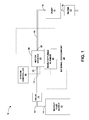
- FIG. 1 is a block diagram of system 10.
- System 10 includes electric motor 20, which operates within external environment 28.
- Electric motor 20 includes motor housing 22, which encloses a substantially-sealed internal environment.
- System 10 further includes pump 17, which includes pump inlet 16, which is connected to outlet 25 on motor housing 22 via conduit 15.
- Pump 17 is configured to create a negative pressure within the substantially-sealed internal environment of motor housing 22 to mitigate potential contamination of external environment 28 with fluid from the internal environment of electric motor 20.
- external environment 28 may be a high-purity controlled environment within an environmental chamber for a manufacturing process, and contamination of external environment 28 may inhibit the manufacturing process.
- the negative pressure within motor housing 22 prevents the contents of motor housing 22 from escaping into external environment 28 in the event of small leaks in the sealing of motor housing 22.
- the negative pressure selected for the substantially-sealed internal environment of motor housing 22 may depend on flow rates and leak sizes system 10 is designed to mitigate. As particular examples, such negative pressure may be selected within the range of about 0.01 millibar to 900 millibar.
- System 10 further includes makeup fluid supply 12, which stores a makeup fluid.
- makeup fluid supply 12 may simply represent a connection to atmospheric air.
- Fluid supply 12 includes outlet 11, which is connected to the substantially-sealed internal environment of motor housing 22 via conduit 13.
- Valve 14 is located within conduit 13 and functions as a regulator.
- Valve 14 combines with pump 17 to control flow of makeup fluid within the substantially-sealed internal environment of motor housing 22.
- the flow of makeup fluid through the substantially-sealed internal environment of motor housing 22 limits contamination of substantially-sealed internal environment with contents of the external environment to facilitate safe operation of motor 20.
- the designed flow rate of makeup fluid through the substantially-sealed internal environment of motor housing 22 may depend on flow rates and leak sizes system 10 is designed to mitigate. As particular examples, such flow rates may be selected from within the range of about 0.01 cubic centimeters per minute up to 10,000 liters per minute depending on the application of system 10.
- the designed flow rate of makeup fluid through the substantially-sealed internal environment of motor housing 22 may further be selected to provide cooling for motor 20, which may prolongs life and improves motor efficiency.
- external environment 28 may comprises gases, such as argon or helium, with relatively low thermal conductivity, such that motor 20 may be subject to overheating or, alternatively, be operated below its rated capacity, without additional cooling, such as the cooling provided by the flow of makeup fluid through the substantially-sealed internal environment of motor housing 22
- Filter 19 is optionally connected to outlet 18 of pump 17.
- Filter 19 is configured to filter fluids exiting outlet 18 of pump 17.
- outlet 18 of pump 17 may be monitored for levels of gas of external environment 28. Relatively higher levels of gas of external environment 28 within outlet 18 of pump 17 indicates less effective sealing within motor 20. In some cases, levels of gas of external environment 28 within outlet 18 of pump 17 may indicate an impending failure of a seal, such as a motor seal. Thus, monitoring for levels of gas of external environment 28 within outlet 18 of pump 17 may facilitate scheduling maintenance to repair or replace degrading seals prior to contamination of external environment 28.
- motor 10 is included within a manufacturing system as it interacts with manufacturing element 24.
- motor 10 may be a positioning motor for manufacturing element 24; for example, manufacturing element 24 may include a laser, material deposition nozzle, or machining element, such as a cutting, milling or drilling element.
- motor 10 may drive manufacturing element 24; for example, manufacturing element 24 may include a pump or machining element.
- the manufacturing element 24 may operate within a controlled environment, which is represented in FIG. 1 as external environment 28.
- Examples of manufacturing processes that operate within a controlled environment include, but are not limited to, semiconductor manufacturing, directed energy deposition, chemical vapor deposition, and/or radioactive material handling.
- Directed energy deposition is generally defined as an additive manufacturing process in which focused thermal energy is used to fuse materials by melting as they are being deposited, as provided by American Society for Testing and Materials (ASTM) designation F2792 - 12a.
- external environment 28 may comprise noble gases, such as argon or helium, such as at least ten percent by weight of argon or helium.
- external environment 28 may consist essentially of noble gases, and may consist essentially of argon to facilitate directed energy deposition.
- the makeup fluid and fluid within housing 22 may consist essentially of oxygen, nitrogen or atmospheric air. This may mitigate risks of electrical shorting of conductors within housing 22 of electric motor 20 due to significant levels of noble gases.
- external environment 28 may comprise different fluids, including gases, liquids and slurries that may be hazardous to the components of electric motor 20.
- pump 17 limits accumulation of contaminants from external environment 28 within housing 22.
- makeup fluid supply 12, valve 14, pump 17 and filter 19 are illustrated in the example of FIG. 1 as being located outside of external environment 28, in other examples, some or all of these components may be within external environment 28. However, fluids leaving pump 17 should be directed outside of external environment 28 to prevent contamination of external environment 28 with such fluids.
- System controller 26 operates to control motor 20 and manufacturing element 24 to implement the manufacturing process of system 10.
- system controller 26 may further control one or both of pump 17 and valve 14 to regulate the fluid flow through housing 22.
- System controller 26 can include a microprocessor or multiple microprocessors capable of executing and/or outputting command signals in response to received and/or stored data.
- system controller 26 can include computer-readable storage, such as read-only memories (ROM), random-access memories (RAM), and/or flash memories, or any other components for running an application and processing data for controlling operations associated with system 10.
- system controller 26 can include instructions and/or data stored as hardware, software, and/or firmware within the one or more memories, storage devices, and/or microprocessors.
- controller 26 can include and/or be associated with surface modeling circuitry, regression analysis circuitry, program code modification circuitry, switches, and/or other types of circuitry, as suited for an automated manufacturing process. In the same or different examples, system controller 26 may be directed by a user input to implement one or more manufacturing processes.
- FIG. 2 is a flow diagram illustrating an example technique for operating an electric motor while mitigating potential contamination of an external environment of the electric motor. For clarity, the techniques of FIG. 2 are describe with respect to system 10, including motor 20 of FIG. 1 .
- Electric motor 20 operates within external environment 28 (30).
- external environment 28 may be a controlled environment for a manufacturing process.
- Pump 17 applies, during the operation of electric motor 20, a negative pressure to the substantially-sealed internal environment within housing 22 of electric motor 32 via conduit 15 (32).
- makeup fluid supply 12 supplies, during the operation of electric motor 20, a makeup fluid via outlet 11 (34).
- makeup fluid supply 12 connected to the substantially-sealed internal environment within housing 22 of electric motor 32 via conduit 13. The negative pressure within the substantially-sealed internal environment of the electric motor mitigates potential contamination of the external environment with the makeup fluid.
- Valve 14 is optionally located within conduit 13 and may function as a regulator.
- the method may further include, during the operation of electric motor 20, operating valve 14 and pump 17 to control flow and/or pressure of the makeup fluid within substantially-sealed internal environment within housing 22 of electric motor 32.
- the controlled flow and/or pressure may be selected to limit contamination of substantially-sealed internal environment with contents of the external environment.
- the method may further include, filtering, during the operation of electric motor 20, filter fluids exiting pump outlet 18 with filter 19.
- the method may include using electric motor 20 to position a manufacturing element 24 as part of a manufacturing process.
- a manufacturing process may include semiconductor manufacturing, directed energy deposition, chemical vapor deposition and/or radioactive material handling.
- processors including one or more microprocessors, digital signal processors (DSPs), application specific integrated circuits (ASICs), field programmable gate arrays (FPGAs), or any other equivalent integrated or discrete logic circuitry, as well as any combinations of such components.
- DSPs digital signal processors
- ASICs application specific integrated circuits
- FPGAs field programmable gate arrays
- processors may generally refer to any of the foregoing logic circuitry, alone or in combination with other logic circuitry, or any other equivalent circuitry.
- a control unit including hardware may also perform one or more of the techniques of this disclosure.
- Such hardware, software, and firmware may be implemented within the same device or within separate devices to support the various techniques described in this disclosure.
- any of the described units, modules or components may be implemented together or separately as discrete but interoperable logic devices. Depiction of different features as modules or units is intended to highlight different functional aspects and does not necessarily imply that such modules or units must be realized by separate hardware, firmware, or software components. Rather, functionality associated with one or more modules or units may be performed by separate hardware, firmware, or software components, or integrated within common or separate hardware, firmware, or software components.
- the techniques described in this disclosure may also be embodied or encoded in a computer system-readable medium, such as a computer system-readable storage medium, containing instructions. Instructions embedded or encoded in a computer system-readable medium, including a computer system-readable storage medium, may cause one or more programmable processors, or other processors, to implement one or more of the techniques described herein, such as when instructions included or encoded in the computer system-readable medium are executed by the one or more processors.
- Computer system readable storage media may include random access memory (RAM), read only memory (ROM), programmable read only memory (PROM), erasable programmable read only memory (EPROM), electronically erasable programmable read only memory (EEPROM), flash memory, a hard disk, a compact disc ROM (CD-ROM), a floppy disk, a cassette, magnetic media, optical media, or other computer system readable media.
- RAM random access memory
- ROM read only memory
- PROM programmable read only memory
- EPROM erasable programmable read only memory
- EEPROM electronically erasable programmable read only memory
- flash memory a hard disk, a compact disc ROM (CD-ROM), a floppy disk, a cassette, magnetic media, optical media, or other computer system readable media.
- an article of manufacture may comprise one or more computer system-readable storage media.
Landscapes
- Engineering & Computer Science (AREA)
- Power Engineering (AREA)
- Motor Or Generator Frames (AREA)
- Motor Or Generator Cooling System (AREA)
Applications Claiming Priority (1)
| Application Number | Priority Date | Filing Date | Title |
|---|---|---|---|
| US201462025789P | 2014-07-17 | 2014-07-17 |
Publications (3)
| Publication Number | Publication Date |
|---|---|
| EP2975737A2 true EP2975737A2 (de) | 2016-01-20 |
| EP2975737A3 EP2975737A3 (de) | 2016-07-13 |
| EP2975737B1 EP2975737B1 (de) | 2017-09-13 |
Family
ID=54146900
Family Applications (1)
| Application Number | Title | Priority Date | Filing Date |
|---|---|---|---|
| EP15176710.0A Active EP2975737B1 (de) | 2014-07-17 | 2015-07-14 | Unterdruckmotordichtung |
Country Status (2)
| Country | Link |
|---|---|
| US (1) | US9929625B2 (de) |
| EP (1) | EP2975737B1 (de) |
Cited By (1)
| Publication number | Priority date | Publication date | Assignee | Title |
|---|---|---|---|---|
| US11612986B2 (en) | 2019-12-17 | 2023-03-28 | Rolls-Royce Corporation | Abrasive coating including metal matrix and ceramic particles |
Families Citing this family (13)
| Publication number | Priority date | Publication date | Assignee | Title |
|---|---|---|---|---|
| US10892140B2 (en) * | 2018-07-27 | 2021-01-12 | Eagle Harbor Technologies, Inc. | Nanosecond pulser bias compensation |
| US11227745B2 (en) | 2018-08-10 | 2022-01-18 | Eagle Harbor Technologies, Inc. | Plasma sheath control for RF plasma reactors |
| US11004660B2 (en) | 2018-11-30 | 2021-05-11 | Eagle Harbor Technologies, Inc. | Variable output impedance RF generator |
| US11430635B2 (en) | 2018-07-27 | 2022-08-30 | Eagle Harbor Technologies, Inc. | Precise plasma control system |
| US11532457B2 (en) | 2018-07-27 | 2022-12-20 | Eagle Harbor Technologies, Inc. | Precise plasma control system |
| US11810761B2 (en) | 2018-07-27 | 2023-11-07 | Eagle Harbor Technologies, Inc. | Nanosecond pulser ADC system |
| US11222767B2 (en) | 2018-07-27 | 2022-01-11 | Eagle Harbor Technologies, Inc. | Nanosecond pulser bias compensation |
| US12456604B2 (en) | 2019-12-24 | 2025-10-28 | Eagle Harbor Technologies, Inc. | Nanosecond pulser RF isolation for plasma systems |
| TWI778449B (zh) | 2019-11-15 | 2022-09-21 | 美商鷹港科技股份有限公司 | 高電壓脈衝電路 |
| EP4486072A3 (de) | 2019-12-24 | 2025-04-09 | Eagle Harbor Technologies, Inc. | Nanosekundenimpuls-hf-isolierung für plasmasysteme |
| US11967484B2 (en) | 2020-07-09 | 2024-04-23 | Eagle Harbor Technologies, Inc. | Ion current droop compensation |
| US11824542B1 (en) | 2022-06-29 | 2023-11-21 | Eagle Harbor Technologies, Inc. | Bipolar high voltage pulser |
| JP7833099B2 (ja) | 2022-09-29 | 2026-03-18 | イーグル ハーバー テクノロジーズ,インク. | 高電圧プラズマ制御 |
Family Cites Families (27)
| Publication number | Priority date | Publication date | Assignee | Title |
|---|---|---|---|---|
| US3258619A (en) | 1966-06-28 | Gas control system for dynamoelectric machines | ||
| US2186232A (en) | 1938-01-29 | 1940-01-09 | Westinghouse Electric & Mfg Co | Ventilation of totally enclosed dynamo-electric machines |
| US2196408A (en) | 1938-04-21 | 1940-04-09 | Westinghouse Electric & Mfg Co | Explosion-resisting motor |
| US2488387A (en) | 1948-03-06 | 1949-11-15 | Westinghouse Electric Corp | Enclosed dynamoelectric machine |
| US3348081A (en) | 1965-09-16 | 1967-10-17 | Gen Electric | Gap pickup rotor with gas segregating baffles |
| US3840762A (en) | 1972-03-22 | 1974-10-08 | Rockwell International Corp | Vacuum-cooled power tool |
| US5212432A (en) | 1989-10-20 | 1993-05-18 | Tokico, Ltd. | Industrial robot |
| ATE137621T1 (de) | 1992-11-04 | 1996-05-15 | Siemens Ag | Austragung von wasserstoff aus einer mit wasserstoff gefüllten elektrischen maschine |
| DE4443427C2 (de) | 1994-12-06 | 2002-04-18 | Siemens Ag | Elektrische Maschine |
| JP3687693B2 (ja) | 1995-11-21 | 2005-08-24 | 株式会社安川電機 | 電動モータ |
| US6008553A (en) | 1998-09-18 | 1999-12-28 | Ford Global Technologies, Inc. | Linear motor with negative pressure cooling circuit |
| JP2000170680A (ja) | 1998-09-30 | 2000-06-20 | Aisin Seiki Co Ltd | 真空ポンプ |
| DE10117398A1 (de) | 2001-04-06 | 2002-10-10 | Miscel Oy Ltd | Elektrischer Asynchronmotor |
| US6830842B2 (en) | 2001-10-24 | 2004-12-14 | General Motors Corporation | Hydrogen purged motor for anode re-circulation blower |
| US6750588B1 (en) * | 2002-06-03 | 2004-06-15 | Christopher W. Gabrys | High performance axial gap alternator motor |
| GB2393584B (en) | 2002-09-26 | 2006-06-21 | Alstom | Gas-cooled generator |
| US7084548B1 (en) * | 2003-07-11 | 2006-08-01 | Gabrys Christopher W | Low cost high speed electrical machine |
| US6794777B1 (en) * | 2003-12-19 | 2004-09-21 | Richard Benito Fradella | Robust minimal-loss flywheel systems |
| AU2005255794B2 (en) | 2004-06-21 | 2008-09-04 | Mitsubishi Denki Kabushiki Kaisha | Totally-enclosed fancooled type motor |
| FR2891416B1 (fr) | 2005-09-29 | 2007-11-02 | Valeo Equip Electr Moteur | Systeme de ventilation pour machines electriques tournantes equipe d'un dispositif de refroidissement par ecoulement force d'un fluide et machine electrique tournante comportant un tel dispositif |
| US7916267B2 (en) | 2006-08-29 | 2011-03-29 | Asml Netherlands B.V. | Lithographic apparatus, and motor cooling device |
| CN101702957B (zh) | 2007-03-15 | 2013-03-27 | 直接传动系统股份有限公司 | 电机的冷却 |
| ES2396989T3 (es) | 2008-10-28 | 2013-03-01 | Siemens Aktiengesellschaft | Disposición para la refrigeración de una máquina eléctrica |
| US8159094B2 (en) | 2009-03-11 | 2012-04-17 | Nidec Motor Corporation | Electric motor having fluid circulation system and methods for cooling an electric motor |
| US7977845B1 (en) | 2010-01-11 | 2011-07-12 | Heitmann Arnold M | Induction motor |
| US8482168B2 (en) | 2010-08-25 | 2013-07-09 | Clean Wave Technologies, Inc. | Systems and methods for fluid cooling of electric machines |
| NO331965B2 (no) | 2010-09-29 | 2012-05-14 | Rolls Royce Marine As | Elektrisk permanentmagnetmotor |
-
2015
- 2015-07-13 US US14/797,801 patent/US9929625B2/en active Active
- 2015-07-14 EP EP15176710.0A patent/EP2975737B1/de active Active
Non-Patent Citations (1)
| Title |
|---|
| None |
Cited By (2)
| Publication number | Priority date | Publication date | Assignee | Title |
|---|---|---|---|---|
| US11612986B2 (en) | 2019-12-17 | 2023-03-28 | Rolls-Royce Corporation | Abrasive coating including metal matrix and ceramic particles |
| US12226878B2 (en) | 2019-12-17 | 2025-02-18 | Rolls-Royce Corporation | Abrasive coating including metal matrix and ceramic particles |
Also Published As
| Publication number | Publication date |
|---|---|
| EP2975737A3 (de) | 2016-07-13 |
| US20160020672A1 (en) | 2016-01-21 |
| US9929625B2 (en) | 2018-03-27 |
| EP2975737B1 (de) | 2017-09-13 |
Similar Documents
| Publication | Publication Date | Title |
|---|---|---|
| US9929625B2 (en) | Negative pressure motor sealing | |
| CN104379499B (zh) | 氢产生装置 | |
| US8851099B2 (en) | Pipe monitoring system and method | |
| US20180259080A1 (en) | Valves and control systems for pressure relief | |
| US7244111B2 (en) | Compressor apparatus and method for the operation of the same | |
| SG182510A1 (en) | Ventilation gas management systems and processes | |
| KR101451189B1 (ko) | 공압 밸브를 연속적으로 작동시키기 위한 솔레노이드 바이패스 시스템 | |
| JPWO2016121075A1 (ja) | 真空処理装置 | |
| CN104128841B (zh) | 转台装置 | |
| CN106463187B (zh) | 用于控制反应堆设备和核反应堆设备中的氧气浓度的方法和装置 | |
| US20050262852A1 (en) | Integration of automated cryopump safety purge | |
| EP4303447A1 (de) | Vakuumpumpe und vakuumauslassvorrichtung | |
| KR102180328B1 (ko) | 냉각재로의 가스 주입 방법과 제어 시스템 및 원자력 발전소 | |
| CN203735772U (zh) | 气瓶柜 | |
| KR101664192B1 (ko) | 기판 처리 장치 및 기판 처리 방법 | |
| US10533134B2 (en) | Methods and apparatuses for selective chemical etching | |
| US20250065462A1 (en) | Temperature control system with flammable heat transfer fluid | |
| US9878283B2 (en) | Recirculating inert gas purification apparatus used with gloveboxes, gloveboxes incorporating the same, thermal protection systems for gloveboxes and methods of using the same | |
| JP2014529089A (ja) | 放射性同位体を生成するための方法及び装置 | |
| JP2010139025A (ja) | 高圧ガス容器弁 | |
| CN106233586A (zh) | 用于电机器的保护系统 | |
| JP2017057754A (ja) | 真空ポンプ | |
| CN106463186A (zh) | 反应堆冷却剂泵的被动型注氮装置 | |
| US20240019880A1 (en) | Flow control arrangements with bypass switches, semiconductor processing systems, and related flow control methods | |
| WO2022230121A1 (ja) | 水素供給システム |
Legal Events
| Date | Code | Title | Description |
|---|---|---|---|
| PUAI | Public reference made under article 153(3) epc to a published international application that has entered the european phase |
Free format text: ORIGINAL CODE: 0009012 |
|
| AK | Designated contracting states |
Kind code of ref document: A2 Designated state(s): AL AT BE BG CH CY CZ DE DK EE ES FI FR GB GR HR HU IE IS IT LI LT LU LV MC MK MT NL NO PL PT RO RS SE SI SK SM TR |
|
| AX | Request for extension of the european patent |
Extension state: BA ME |
|
| PUAL | Search report despatched |
Free format text: ORIGINAL CODE: 0009013 |
|
| AK | Designated contracting states |
Kind code of ref document: A3 Designated state(s): AL AT BE BG CH CY CZ DE DK EE ES FI FR GB GR HR HU IE IS IT LI LT LU LV MC MK MT NL NO PL PT RO RS SE SI SK SM TR |
|
| AX | Request for extension of the european patent |
Extension state: BA ME |
|
| RIC1 | Information provided on ipc code assigned before grant |
Ipc: H02K 9/19 20060101ALI20160606BHEP Ipc: H02K 9/10 20060101ALI20160606BHEP Ipc: H02K 9/12 20060101ALI20160606BHEP Ipc: H02K 5/12 20060101AFI20160606BHEP |
|
| 17P | Request for examination filed |
Effective date: 20170105 |
|
| RBV | Designated contracting states (corrected) |
Designated state(s): AL AT BE BG CH CY CZ DE DK EE ES FI FR GB GR HR HU IE IS IT LI LT LU LV MC MK MT NL NO PL PT RO RS SE SI SK SM TR |
|
| GRAP | Despatch of communication of intention to grant a patent |
Free format text: ORIGINAL CODE: EPIDOSNIGR1 |
|
| RIC1 | Information provided on ipc code assigned before grant |
Ipc: H02K 9/12 20060101ALI20170227BHEP Ipc: H02K 9/19 20060101ALI20170227BHEP Ipc: H02K 9/10 20060101ALI20170227BHEP Ipc: H02K 5/12 20060101AFI20170227BHEP |
|
| INTG | Intention to grant announced |
Effective date: 20170323 |
|
| RIN1 | Information on inventor provided before grant (corrected) |
Inventor name: BAXTER, GAVIN Inventor name: SHUCK, QUINLAN YEE |
|
| GRAS | Grant fee paid |
Free format text: ORIGINAL CODE: EPIDOSNIGR3 |
|
| GRAA | (expected) grant |
Free format text: ORIGINAL CODE: 0009210 |
|
| AK | Designated contracting states |
Kind code of ref document: B1 Designated state(s): AL AT BE BG CH CY CZ DE DK EE ES FI FR GB GR HR HU IE IS IT LI LT LU LV MC MK MT NL NO PL PT RO RS SE SI SK SM TR |
|
| REG | Reference to a national code |
Ref country code: GB Ref legal event code: FG4D |
|
| REG | Reference to a national code |
Ref country code: CH Ref legal event code: EP |
|
| REG | Reference to a national code |
Ref country code: IE Ref legal event code: FG4D |
|
| REG | Reference to a national code |
Ref country code: SE Ref legal event code: TRGR |
|
| REG | Reference to a national code |
Ref country code: AT Ref legal event code: REF Ref document number: 929045 Country of ref document: AT Kind code of ref document: T Effective date: 20171015 |
|
| REG | Reference to a national code |
Ref country code: DE Ref legal event code: R096 Ref document number: 602015004649 Country of ref document: DE |
|
| REG | Reference to a national code |
Ref country code: NL Ref legal event code: MP Effective date: 20170913 |
|
| REG | Reference to a national code |
Ref country code: LT Ref legal event code: MG4D |
|
| PG25 | Lapsed in a contracting state [announced via postgrant information from national office to epo] |
Ref country code: NO Free format text: LAPSE BECAUSE OF FAILURE TO SUBMIT A TRANSLATION OF THE DESCRIPTION OR TO PAY THE FEE WITHIN THE PRESCRIBED TIME-LIMIT Effective date: 20171213 Ref country code: HR Free format text: LAPSE BECAUSE OF FAILURE TO SUBMIT A TRANSLATION OF THE DESCRIPTION OR TO PAY THE FEE WITHIN THE PRESCRIBED TIME-LIMIT Effective date: 20170913 Ref country code: FI Free format text: LAPSE BECAUSE OF FAILURE TO SUBMIT A TRANSLATION OF THE DESCRIPTION OR TO PAY THE FEE WITHIN THE PRESCRIBED TIME-LIMIT Effective date: 20170913 Ref country code: LT Free format text: LAPSE BECAUSE OF FAILURE TO SUBMIT A TRANSLATION OF THE DESCRIPTION OR TO PAY THE FEE WITHIN THE PRESCRIBED TIME-LIMIT Effective date: 20170913 |
|
| REG | Reference to a national code |
Ref country code: AT Ref legal event code: MK05 Ref document number: 929045 Country of ref document: AT Kind code of ref document: T Effective date: 20170913 |
|
| PG25 | Lapsed in a contracting state [announced via postgrant information from national office to epo] |
Ref country code: LV Free format text: LAPSE BECAUSE OF FAILURE TO SUBMIT A TRANSLATION OF THE DESCRIPTION OR TO PAY THE FEE WITHIN THE PRESCRIBED TIME-LIMIT Effective date: 20170913 Ref country code: GR Free format text: LAPSE BECAUSE OF FAILURE TO SUBMIT A TRANSLATION OF THE DESCRIPTION OR TO PAY THE FEE WITHIN THE PRESCRIBED TIME-LIMIT Effective date: 20171214 Ref country code: ES Free format text: LAPSE BECAUSE OF FAILURE TO SUBMIT A TRANSLATION OF THE DESCRIPTION OR TO PAY THE FEE WITHIN THE PRESCRIBED TIME-LIMIT Effective date: 20170913 Ref country code: BG Free format text: LAPSE BECAUSE OF FAILURE TO SUBMIT A TRANSLATION OF THE DESCRIPTION OR TO PAY THE FEE WITHIN THE PRESCRIBED TIME-LIMIT Effective date: 20171213 Ref country code: RS Free format text: LAPSE BECAUSE OF FAILURE TO SUBMIT A TRANSLATION OF THE DESCRIPTION OR TO PAY THE FEE WITHIN THE PRESCRIBED TIME-LIMIT Effective date: 20170913 |
|
| PG25 | Lapsed in a contracting state [announced via postgrant information from national office to epo] |
Ref country code: NL Free format text: LAPSE BECAUSE OF FAILURE TO SUBMIT A TRANSLATION OF THE DESCRIPTION OR TO PAY THE FEE WITHIN THE PRESCRIBED TIME-LIMIT Effective date: 20170913 |
|
| PG25 | Lapsed in a contracting state [announced via postgrant information from national office to epo] |
Ref country code: PL Free format text: LAPSE BECAUSE OF FAILURE TO SUBMIT A TRANSLATION OF THE DESCRIPTION OR TO PAY THE FEE WITHIN THE PRESCRIBED TIME-LIMIT Effective date: 20170913 Ref country code: RO Free format text: LAPSE BECAUSE OF FAILURE TO SUBMIT A TRANSLATION OF THE DESCRIPTION OR TO PAY THE FEE WITHIN THE PRESCRIBED TIME-LIMIT Effective date: 20170913 Ref country code: CZ Free format text: LAPSE BECAUSE OF FAILURE TO SUBMIT A TRANSLATION OF THE DESCRIPTION OR TO PAY THE FEE WITHIN THE PRESCRIBED TIME-LIMIT Effective date: 20170913 |
|
| PG25 | Lapsed in a contracting state [announced via postgrant information from national office to epo] |
Ref country code: SK Free format text: LAPSE BECAUSE OF FAILURE TO SUBMIT A TRANSLATION OF THE DESCRIPTION OR TO PAY THE FEE WITHIN THE PRESCRIBED TIME-LIMIT Effective date: 20170913 Ref country code: AT Free format text: LAPSE BECAUSE OF FAILURE TO SUBMIT A TRANSLATION OF THE DESCRIPTION OR TO PAY THE FEE WITHIN THE PRESCRIBED TIME-LIMIT Effective date: 20170913 Ref country code: IT Free format text: LAPSE BECAUSE OF FAILURE TO SUBMIT A TRANSLATION OF THE DESCRIPTION OR TO PAY THE FEE WITHIN THE PRESCRIBED TIME-LIMIT Effective date: 20170913 Ref country code: SM Free format text: LAPSE BECAUSE OF FAILURE TO SUBMIT A TRANSLATION OF THE DESCRIPTION OR TO PAY THE FEE WITHIN THE PRESCRIBED TIME-LIMIT Effective date: 20170913 Ref country code: EE Free format text: LAPSE BECAUSE OF FAILURE TO SUBMIT A TRANSLATION OF THE DESCRIPTION OR TO PAY THE FEE WITHIN THE PRESCRIBED TIME-LIMIT Effective date: 20170913 Ref country code: IS Free format text: LAPSE BECAUSE OF FAILURE TO SUBMIT A TRANSLATION OF THE DESCRIPTION OR TO PAY THE FEE WITHIN THE PRESCRIBED TIME-LIMIT Effective date: 20180113 |
|
| REG | Reference to a national code |
Ref country code: DE Ref legal event code: R097 Ref document number: 602015004649 Country of ref document: DE |
|
| PLBE | No opposition filed within time limit |
Free format text: ORIGINAL CODE: 0009261 |
|
| STAA | Information on the status of an ep patent application or granted ep patent |
Free format text: STATUS: NO OPPOSITION FILED WITHIN TIME LIMIT |
|
| REG | Reference to a national code |
Ref country code: FR Ref legal event code: PLFP Year of fee payment: 4 |
|
| PG25 | Lapsed in a contracting state [announced via postgrant information from national office to epo] |
Ref country code: DK Free format text: LAPSE BECAUSE OF FAILURE TO SUBMIT A TRANSLATION OF THE DESCRIPTION OR TO PAY THE FEE WITHIN THE PRESCRIBED TIME-LIMIT Effective date: 20170913 |
|
| 26N | No opposition filed |
Effective date: 20180614 |
|
| PG25 | Lapsed in a contracting state [announced via postgrant information from national office to epo] |
Ref country code: SI Free format text: LAPSE BECAUSE OF FAILURE TO SUBMIT A TRANSLATION OF THE DESCRIPTION OR TO PAY THE FEE WITHIN THE PRESCRIBED TIME-LIMIT Effective date: 20170913 |
|
| REG | Reference to a national code |
Ref country code: CH Ref legal event code: PL |
|
| PG25 | Lapsed in a contracting state [announced via postgrant information from national office to epo] |
Ref country code: MC Free format text: LAPSE BECAUSE OF FAILURE TO SUBMIT A TRANSLATION OF THE DESCRIPTION OR TO PAY THE FEE WITHIN THE PRESCRIBED TIME-LIMIT Effective date: 20170913 Ref country code: LU Free format text: LAPSE BECAUSE OF NON-PAYMENT OF DUE FEES Effective date: 20180714 |
|
| REG | Reference to a national code |
Ref country code: BE Ref legal event code: MM Effective date: 20180731 |
|
| REG | Reference to a national code |
Ref country code: IE Ref legal event code: MM4A |
|
| PG25 | Lapsed in a contracting state [announced via postgrant information from national office to epo] |
Ref country code: CH Free format text: LAPSE BECAUSE OF NON-PAYMENT OF DUE FEES Effective date: 20180731 Ref country code: LI Free format text: LAPSE BECAUSE OF NON-PAYMENT OF DUE FEES Effective date: 20180731 Ref country code: IE Free format text: LAPSE BECAUSE OF NON-PAYMENT OF DUE FEES Effective date: 20180714 |
|
| PG25 | Lapsed in a contracting state [announced via postgrant information from national office to epo] |
Ref country code: BE Free format text: LAPSE BECAUSE OF NON-PAYMENT OF DUE FEES Effective date: 20180731 |
|
| PG25 | Lapsed in a contracting state [announced via postgrant information from national office to epo] |
Ref country code: MT Free format text: LAPSE BECAUSE OF NON-PAYMENT OF DUE FEES Effective date: 20180714 |
|
| GBPC | Gb: european patent ceased through non-payment of renewal fee |
Effective date: 20190714 |
|
| PG25 | Lapsed in a contracting state [announced via postgrant information from national office to epo] |
Ref country code: TR Free format text: LAPSE BECAUSE OF FAILURE TO SUBMIT A TRANSLATION OF THE DESCRIPTION OR TO PAY THE FEE WITHIN THE PRESCRIBED TIME-LIMIT Effective date: 20170913 |
|
| PG25 | Lapsed in a contracting state [announced via postgrant information from national office to epo] |
Ref country code: GB Free format text: LAPSE BECAUSE OF NON-PAYMENT OF DUE FEES Effective date: 20190714 |
|
| PG25 | Lapsed in a contracting state [announced via postgrant information from national office to epo] |
Ref country code: PT Free format text: LAPSE BECAUSE OF FAILURE TO SUBMIT A TRANSLATION OF THE DESCRIPTION OR TO PAY THE FEE WITHIN THE PRESCRIBED TIME-LIMIT Effective date: 20170913 |
|
| PG25 | Lapsed in a contracting state [announced via postgrant information from national office to epo] |
Ref country code: CY Free format text: LAPSE BECAUSE OF FAILURE TO SUBMIT A TRANSLATION OF THE DESCRIPTION OR TO PAY THE FEE WITHIN THE PRESCRIBED TIME-LIMIT Effective date: 20170913 Ref country code: HU Free format text: LAPSE BECAUSE OF FAILURE TO SUBMIT A TRANSLATION OF THE DESCRIPTION OR TO PAY THE FEE WITHIN THE PRESCRIBED TIME-LIMIT; INVALID AB INITIO Effective date: 20150714 Ref country code: MK Free format text: LAPSE BECAUSE OF NON-PAYMENT OF DUE FEES Effective date: 20170913 |
|
| PG25 | Lapsed in a contracting state [announced via postgrant information from national office to epo] |
Ref country code: AL Free format text: LAPSE BECAUSE OF FAILURE TO SUBMIT A TRANSLATION OF THE DESCRIPTION OR TO PAY THE FEE WITHIN THE PRESCRIBED TIME-LIMIT Effective date: 20170913 |
|
| PGFP | Annual fee paid to national office [announced via postgrant information from national office to epo] |
Ref country code: FR Payment date: 20200728 Year of fee payment: 6 |
|
| PGFP | Annual fee paid to national office [announced via postgrant information from national office to epo] |
Ref country code: SE Payment date: 20200727 Year of fee payment: 6 |
|
| PG25 | Lapsed in a contracting state [announced via postgrant information from national office to epo] |
Ref country code: SE Free format text: LAPSE BECAUSE OF NON-PAYMENT OF DUE FEES Effective date: 20210715 Ref country code: FR Free format text: LAPSE BECAUSE OF NON-PAYMENT OF DUE FEES Effective date: 20210731 |
|
| P01 | Opt-out of the competence of the unified patent court (upc) registered |
Effective date: 20230528 |
|
| PGFP | Annual fee paid to national office [announced via postgrant information from national office to epo] |
Ref country code: DE Payment date: 20250728 Year of fee payment: 11 |