EP2975743B1 - Moteur électrique et dispositif électrique équipé du moteur électrique - Google Patents
Moteur électrique et dispositif électrique équipé du moteur électrique Download PDFInfo
- Publication number
- EP2975743B1 EP2975743B1 EP14762436.5A EP14762436A EP2975743B1 EP 2975743 B1 EP2975743 B1 EP 2975743B1 EP 14762436 A EP14762436 A EP 14762436A EP 2975743 B1 EP2975743 B1 EP 2975743B1
- Authority
- EP
- European Patent Office
- Prior art keywords
- dielectric
- electric motor
- dielectric layer
- rotation body
- shaft center
- Prior art date
- Legal status (The legal status is an assumption and is not a legal conclusion. Google has not performed a legal analysis and makes no representation as to the accuracy of the status listed.)
- Active
Links
Images





Classifications
-
- H—ELECTRICITY
- H02—GENERATION; CONVERSION OR DISTRIBUTION OF ELECTRIC POWER
- H02K—DYNAMO-ELECTRIC MACHINES
- H02K1/00—Details of the magnetic circuit
- H02K1/06—Details of the magnetic circuit characterised by the shape, form or construction
- H02K1/22—Rotating parts of the magnetic circuit
- H02K1/27—Rotor cores with permanent magnets
- H02K1/2706—Inner rotors
- H02K1/272—Inner rotors the magnetisation axis of the magnets being perpendicular to the rotor axis
- H02K1/274—Inner rotors the magnetisation axis of the magnets being perpendicular to the rotor axis the rotor consisting of two or more circumferentially positioned magnets
- H02K1/2753—Inner rotors the magnetisation axis of the magnets being perpendicular to the rotor axis the rotor consisting of two or more circumferentially positioned magnets the rotor consisting of magnets or groups of magnets arranged with alternating polarity
- H02K1/278—Surface mounted magnets; Inset magnets
-
- H—ELECTRICITY
- H02—GENERATION; CONVERSION OR DISTRIBUTION OF ELECTRIC POWER
- H02K—DYNAMO-ELECTRIC MACHINES
- H02K5/00—Casings; Enclosures; Supports
- H02K5/04—Casings or enclosures characterised by the shape, form or construction thereof
- H02K5/16—Means for supporting bearings, e.g. insulating supports or means for fitting bearings in the bearing-shields
- H02K5/161—Means for supporting bearings, e.g. insulating supports or means for fitting bearings in the bearing-shields radially supporting the rotary shaft at both ends of the rotor
-
- H—ELECTRICITY
- H02—GENERATION; CONVERSION OR DISTRIBUTION OF ELECTRIC POWER
- H02K—DYNAMO-ELECTRIC MACHINES
- H02K1/00—Details of the magnetic circuit
- H02K1/06—Details of the magnetic circuit characterised by the shape, form or construction
- H02K1/22—Rotating parts of the magnetic circuit
- H02K1/27—Rotor cores with permanent magnets
- H02K1/2706—Inner rotors
- H02K1/272—Inner rotors the magnetisation axis of the magnets being perpendicular to the rotor axis
- H02K1/274—Inner rotors the magnetisation axis of the magnets being perpendicular to the rotor axis the rotor consisting of two or more circumferentially positioned magnets
- H02K1/2753—Inner rotors the magnetisation axis of the magnets being perpendicular to the rotor axis the rotor consisting of two or more circumferentially positioned magnets the rotor consisting of magnets or groups of magnets arranged with alternating polarity
- H02K1/276—Magnets embedded in the magnetic core, e.g. interior permanent magnets [IPM]
-
- H—ELECTRICITY
- H02—GENERATION; CONVERSION OR DISTRIBUTION OF ELECTRIC POWER
- H02K—DYNAMO-ELECTRIC MACHINES
- H02K1/00—Details of the magnetic circuit
- H02K1/06—Details of the magnetic circuit characterised by the shape, form or construction
- H02K1/22—Rotating parts of the magnetic circuit
- H02K1/28—Means for mounting or fastening rotating magnetic parts on to, or to, the rotor structures
- H02K1/30—Means for mounting or fastening rotating magnetic parts on to, or to, the rotor structures using intermediate parts, e.g. spiders
-
- H—ELECTRICITY
- H02—GENERATION; CONVERSION OR DISTRIBUTION OF ELECTRIC POWER
- H02K—DYNAMO-ELECTRIC MACHINES
- H02K11/00—Structural association of dynamo-electric machines with electric components or with devices for shielding, monitoring or protection
- H02K11/30—Structural association with control circuits or drive circuits
- H02K11/33—Drive circuits, e.g. power electronics
-
- H—ELECTRICITY
- H02—GENERATION; CONVERSION OR DISTRIBUTION OF ELECTRIC POWER
- H02K—DYNAMO-ELECTRIC MACHINES
- H02K11/00—Structural association of dynamo-electric machines with electric components or with devices for shielding, monitoring or protection
- H02K11/30—Structural association with control circuits or drive circuits
- H02K11/38—Control circuits or drive circuits associated with geared commutator motors of the worm-and-wheel type
-
- H—ELECTRICITY
- H02—GENERATION; CONVERSION OR DISTRIBUTION OF ELECTRIC POWER
- H02K—DYNAMO-ELECTRIC MACHINES
- H02K7/00—Arrangements for handling mechanical energy structurally associated with dynamo-electric machines, e.g. structural association with mechanical driving motors or auxiliary dynamo-electric machines
- H02K7/003—Couplings; Details of shafts
-
- H—ELECTRICITY
- H02—GENERATION; CONVERSION OR DISTRIBUTION OF ELECTRIC POWER
- H02K—DYNAMO-ELECTRIC MACHINES
- H02K5/00—Casings; Enclosures; Supports
- H02K5/04—Casings or enclosures characterised by the shape, form or construction thereof
- H02K5/16—Means for supporting bearings, e.g. insulating supports or means for fitting bearings in the bearing-shields
- H02K5/173—Means for supporting bearings, e.g. insulating supports or means for fitting bearings in the bearing-shields using bearings with rolling contact, e.g. ball bearings
- H02K5/1732—Means for supporting bearings, e.g. insulating supports or means for fitting bearings in the bearing-shields using bearings with rolling contact, e.g. ball bearings radially supporting the rotary shaft at both ends of the rotor
Definitions
- the present invention relates to an electric motor improved so as to reduce an occurrence of electric corrosion, particularly in the bearings, and also relates to an electrical device equipped with the motor.
- PWM pulse width modulation
- a shaft voltage contains high-frequency components caused by switching. If the shaft voltage reaches a value that causes insulation breakdown of the oil film existed in the bearings, a small current flows into the bearings, causing electric corrosion in them. If the electric corrosion proceeds, the inner or outer rings of the bearings or the bearing balls cause undulating abrasion, possibly generating abnormal sound. The sound is one main cause of malfunction of the electric motor.
- Patent Literature 1 has proposed a technique in which the rotor includes a dielectric layer. This structure reduces the shaft voltage, and hence, reduces occurrence of the electric corrosion.
- a stator, a rotor, bearings, and conductive brackets are provided.
- the stator has a stator iron core having a winding wound thereon.
- the rotor has a rotating body that holds a permanent magnet in the circumferential direction so that the permanent magnet faces the stator, and a shaft that has the rotating body fastened thereto so as to penetrate through the center of the rotating body.
- Both of the bearing on the output shaft side and the bearing opposite the output shaft side journal the shaft.
- One of the brackets fixes the bearing on the output shaft side, and the other of the brackets fixes the bracket opposite the output shaft side.
- the brackets are electrically connected to each other, and a dielectric layer is formed between the shaft and the outer periphery of the rotating body.
- the electric motor of the present invention includes a stator, a rotor, a pair of bearings, and a pair of brackets.
- the stator includes a stator core around which a winding is wound.
- the rotor includes a rotation body including a permanent magnet extending circumferentially and facing the stator, and a shaft passing through the shaft center of the rotation body.
- the pair of bearings support the shaft rotatably, and the pair of brackets fix the bearings.
- the rotation body includes an outer iron core, an inner iron core, and a dielectric layer.
- the outer iron core is located in the outer side of the rotation body.
- the inner iron core is fixed to the shaft.
- the dielectric layer is located between the inner and outer iron cores.
- the dielectric layer includes at least two dielectric bodies different in dielectric constant.
- a shaft voltage is settable in an appropriate range. More specifically, the motor includes a rotation body including a plurality of dielectrics.
- the plurality of dielectrics are, for example, multi-layered resins different in dielectric constant. This structure allows the capacitance between the inner and outer cores to be easily changed.
- the motor having an appropriate shaft voltage is provided by changing the capacitance between the inner and outer cores.
- the present invention is able to provide a motor that effectively reduces electric corrosion in the bearings, and also to provide an electrical device that is equipped with a motor that effectively reduces electric corrosion in the bearings.
- the conventional electric motor has the following points on which care should be taken.
- the capacitance of the dielectric layer is used to reduce the high-frequency voltage induced by the bearing inner rings. It is, however, sometimes difficult to make the dielectric layer suitable to obtain an appropriate shaft voltage.
- an appropriate shaft voltage can be obtained if the capacitance of the dielectric layer can be changed flexibly.
- the capacitance is changed by the methods described below.
- the conventional motor includes a rotor including a rotation body and a shaft.
- the rotation body includes an outer iron core, an inner iron core, and a dielectric layer located between the inner and outer iron cores.
- the dielectric layer is made of an insulating resin.
- One of the above-mentioned methods is to change the distance between the inner and outer iron cores of the rotation body. Changing the distance between the inner and outer iron cores changes the thickness of the insulating resin. The capacitance is changed by changing the thickness of the insulating resin changes.
- Another method is to change the lengths of the inner and outer iron cores along the shaft center. Changing the lengths of the inner and outer iron cores along the shaft center changes the area where the cores face each other. The capacitance is changed by changing the area where the cores face each other.
- Still another method is to change the dielectric constant of the insulating resin from which the dielectric layer is made.
- the capacitance is changed by changing the dielectric constant of the insulating resin.
- the space available for the installation of the motor is roughly determined according to the electrical device. Therefore, the size of the motor is determined according to the space available, and the size of the rotor used in the motor is automatically determined.
- the size of rotors is generally standardized, and it is difficult to greatly change the standardized size according to the motor. If the size of a rotor is changed, there are the following cautions. Changing the shape of the iron cores of the rotor requires changing the molds for them, which is not easy because it needs cost and time.
- the outer iron core serves as a magnet yoke, and its length along the shaft center affects the efficiency and other properties of the motor.
- the inner iron core is fixed to the axis. The length of the inner iron core along the shaft center affects the strength of the fixation between the rotor and the shaft. Thus, it is not easy to change the inner and outer iron cores.
- the resin material can be changed. It is, however, necessary to evaluate items of property other than the dielectric constant, such as the strength. The large number of items of property to be evaluated makes it difficult to change the resin material.
- the shaft voltage changes also depending on the electrical device in which the electric motor is installed. It is, therefore, very difficult to control the shaft voltage in an appropriate range by changing the resin material alone without changing the shape of the iron cores or their lengths along the shaft center.
- FIG. 1 is a sectional view of an electric motor according to a first exemplary embodiment of the present invention.
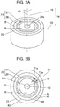
- FIG. 2A is a perspective view of a rotation body of the motor according to the first exemplary embodiment of the present invention.
- FIG. 2B is a top view of the rotation body of the motor according to the first exemplary embodiment of the present invention.
- FIG. 2C is a top view of another example of the rotation body, which is different from the one shown in FIG. 2B , of the motor according to first exemplary embodiment of the present invention.
- FIG. 2D is a top view of still another example of the rotation body of the motor according to first exemplary embodiment of the present invention.
- FIG. 2E is a top view of still another example of the rotation body of the motor according to the first exemplary embodiment of the present invention.
- FIG. 2F is a sectional view taken along line 2F-2F shown in FIG. 2E .
- FIG. 2G is a sectional view taken along line 2G-2G shown in FIG. 2E
- the first exemplary embodiment will describe an example of the electric motor mounted in an electrical device.
- the motor is a brushless motor and an inner rotor type.
- a rotor is rotatably disposed inside the stator.
- brushless motor 40 which is the electric motor according to the first exemplary embodiment of the present invention, includes stator 10, rotor 14, a pair of bearings 15, and a pair of brackets 17 and 24.
- Stator 10 includes stator winding 12 as a winding, and stator core 11 around which stator winding 12 is wound.
- Rotor 14 includes rotation body 20 and shaft 16.
- Rotation body 20 includes a permanent magnet, which extends circumferentially and faces stator 10. The permanent magnet is hereinafter referred to simply as magnet 22.
- Shaft 16 passes through shaft center 42 of rotation body 20.
- the pair of bearings 15 rotatably support shaft 16.
- the pair of brackets 17 and 24 fix bearings 15.
- Rotation body 20 includes outer iron core 25, inner iron core 26, and dielectric layer 23.
- Outer core 25 is located in the outer side of rotation body 20.
- Inner core 26 is fixed to shaft 16.
- Dielectric layer 23 is located between outer and inner cores 25 and 26, and includes at least two dielectric bodies different in dielectric constant.
- dielectric layer 23 has dielectric bodies formed in at least two layers from shaft center 42 outward in the direction orthogonal to shaft center 42.
- the phrase "the direction orthogonal to shaft center 42" indicates the radial direction of cylindrical rotation body 20 as shown in FIGS. 2B and 2D .
- Dielectric layer 23 used in the first exemplary embodiment includes two layers of dielectrics. A dielectric body located on the shaft 16 side is referred to internal dielectric body 27. A dielectric body located on the outer circumferential side is referred to external dielectric body 28.
- FIGS. 2E to 2G Further examples of rotation body 20 are shown in FIGS. 2E to 2G .
- internal dielectric body 27 has holes 41 penetrating it along shaft center 42. Holes 41 may alternatively be provided in external dielectric body 28 or in both internal and external dielectric bodies 27 and 28.
- internal dielectric body 27 may have recesses 41a on its surface 23a along shaft center 42 as shown in FIGS. 2E and 2G . Unlike holes 41, recesses 41a do not penetrate internal dielectric body 27, and their depth is determined according to the required dielectric constant.
- recesses 41a may alternatively be formed on the surface opposite to surface 23a or both of them along shaft center 42. Further alternatively, in internal dielectric body 27, recesses 41a may be formed in external dielectric body 28, or holes 41 may be formed in both internal and external dielectric bodies 27 and 28.
- holes 41 and recesses 41a may have an oval, polygonal, or other cross section if necessary.
- the above-described configurations can change the capacitance between the outer and inner cores, thereby providing an electric motor having an appropriate shaft voltage.
- the motor effectively reduces occurrence of electric corrosion in the bearings.
- stator core 11 which has stator winding 12 wound around it.
- Stator 10 includes insulating resin 13 as an insulator for providing electrical isolation between core 11 and winding 12.
- Stator core 11 is fixed inside motor case 19 together with other members.
- rotor 14 has an approximately cylindrical outer shape.
- Stator 10 may be formed by molding an insulating resin.
- Rotor 14 is placed inside stator 10 with a space between them. As shown in FIG. 2A , rotor 14 includes rotation body 20 and shaft 16. Rotation body 20 is columnar, but may alternatively be discoid. Shaft 16 passes through shaft center 42 of rotation body 20 and is fixed to rotation body 20. Rotation body 20 includes magnet 22 as a permanent magnet extending circumferentially and facing the inner side of the stator. Magnet 22 can be, for example, a ferrite resin magnet or a ferrite sintered magnet.
- rotation body 20 has outer core 25, dielectric layer 23, and inner core 26 arranged in that order from magnet 22 at the outermost position toward shaft 16 at the innermost position.
- Outer core 25 is located in the outer side of rotation body 20.
- Inner core 26 is located in the inner side of rotation body 20.
- rotation body 20 of the first exemplary embodiment includes the rotor core including outer and inner cores 25 and 26, dielectric layer 23, and magnet 22, all of which are molded integrally.
- the inner side of stator 10 and the outer side of rotation body 20 face each other.
- bearings 15 are attached to shaft 16 of rotor 14 so as to support shaft 16.
- Bearings 15 are cylindrical and include a plurality of iron balls.
- One of bearings 15 is fixed to metal bracket 17 molded integrally with a molding resin, whereas the other of bearings 15 is fixed to metal bracket 24.
- shaft 16 is supported by bearings 15, allowing rotor 14 to rotate.
- Brushless motor 40 includes printed circuit board 18 in motor case 19.
- Board 18 includes a driving circuit equipped with a control circuit.
- the connecting wires includes a lead wire for applying a control voltage to board 18 in order to control the power supply voltages of stator winding 12 and the control circuit, and the number of revolutions.
- the connecting wires further include a ground wire to the control circuit.
- stator core 11 When the drive current is supplied to stator winding 12, stator core 11 generates a magnetic field.
- the magnetic field generated by stator core 11 and the magnetic field generated by magnet 22 generate suction and repulsive forces according to the polarities of these magnetic fields. The suction and repulsive forces allow rotor 14 to rotate about shaft 16.
- rotation body 20 has outer core 25, dielectric layer 23 including internal and external dielectric bodies 27 and 28, and inner core 26 arranged in that order from magnet 22 at the outermost position toward shaft 16 at the innermost position.
- Dielectric layer 23 is made of insulating resins. The resins are hereinafter referred to also as the dielectric bodies. In the first exemplary embodiment, dielectric layer 23 is provided to reduce occurrence of electric corrosion.
- Rotation body 20 includes magnet 22, outer core 25, dielectric layer 23, and inner core 26, all of which are molded integrally.
- Inner core 26 has, in its inside, shaft insertion hole 26b for inserting shaft 16.
- Shaft 16 is fixed to inner core 26 in shaft insertion hole 26b.
- Shaft 16 is fixed to rotation body 20 via shaft insertion hole 26b so as to form rotor 14.
- Rotor 14 is supported by the bearings.
- dielectric layer 23 includes internal and external dielectric bodies 27 and 28, which are insulators.
- Dielectric layer 23 has dielectric bodies 27 and 28 arranged in two layers in the direction orthogonal to shaft center 42. Internal and external dielectric bodies 27 and 28 arranged in two layers divide outer and inner cores 25 and 26 in such a manner as to be serially isolated from each other.
- Internal and external dielectric bodies 27 and 28 of dielectric layer 23 are made of insulating resins different in dielectric constant from each other.
- the dielectric constants are controlled within predetermined ranges.
- a high-frequency current flows across outer and inner cores 25 and 26.
- bearings have electric corrosion for the following reasons.
- the impedance is generally high between the stator core and the brackets although there is a structural difference between different motors. This impedance is referred to as the stator-core-side impedance. In contrast, the impedance between the rotation body and the shaft is low and is referred to as the rotation-bodyside impedance.
- the stator-core-side impedance includes mainly two impedances. That is, there are impedance between one bracket and the stator core, and impedance between the other bracket and the stator core, with reference to the stator core.
- the pair of brackets are respectively fixed to corresponding outer rings of the pair of bearings.
- the rotation-body-side impedance is generated between the rotation body not including the dielectric layer and the shaft to which the rotation body is fixed.
- the rotation-body-side impedance is low because the rotation body and the shaft are electrically connected to each other.
- the inner rings of the pair of bearings are fixed to the shaft.
- the brushless motor has an equivalent circuit in which the stator-core-side impedance and the rotation-body-side impedance have been converted into each other.
- the brushless motor is driven by a PWM inverter.
- a high-frequency current is generated due to pulse-width modulation by the stator core and other components.
- the generated high-frequency current flows into the equivalent circuit in which the stator-core-side impedance and the rotation-body-side impedance have been converted into each other.
- a potential difference is generated due to the high-frequency current between the outer rings of the bearings electrically connected to the respective brackets and the inner rings electrically connected to the shaft. If the potential difference is high, the bearings have electric corrosion.
- the rotation body has a high impedance to reduce an occurrence of electric corrosion in the first exemplary embodiment.
- cores included into rotation body 20 are formed of outer core 25 and inner core 26.
- Cores included into rotation body 20 have dielectric layer 23 between outer core 25 and inner core 26. Dielectric layer 23 allows rotation body 20 to be equivalent to the circuit to which the capacitance is connected in series. Thus, an increase in the impedance of rotation body 20 results in an increase in the impedance of rotor 14.
- the impedance of a rotor is low when it includes a rotation body including iron cores alone and having a low impedance.
- rotor 14 of the first exemplary embodiment has a high impedance.
- the "high" impedance is about the same level as that obtained by electrically connecting bracket 17 with bearings 15 and other components.
- An increase in the impedance of rotor 14 results in an increase in the voltage drop due to the high-frequency current flowing from rotation body 20 to shaft 16. This reduces the potential generated in shaft 16 due to the high-frequency current.
- the outer rings of bearings 15 are electrically connected to bracket 17.
- the inner rings of bearings 15 are electrically connected to shaft 16.
- brushless motor 40 can reduce the potential difference between the inner and outer rings of bearings 15 caused by the high-frequency current. Consequently, a low potential difference is maintained between the inner and outer rings of bearings 15. This reduces the electric corrosion in bearings 15.
- Rotation body 20 will now be described in detail.
- rotation body 20 is in the shape of a cylinder having a plurality of layers.
- these layers includes inner core 26 formed of a core, dielectric layer 23 formed of an iron core, outer core 25 formed of an iron core, and magnet 22 arranged in that order from shaft 16 at the innermost position toward magnet 22 at the outermost position.
- Iron cores forming outer core 25 and inner core 26, dielectric bodies forming dielectric layer 23, and magnet 22 are made from different materials from each other.
- the dielectric bodies are made of insulating resins.
- boundary 43 between outer core 25 and magnet 22 is provided with projections 44 and recesses 45, which are engaged with each other in the direction orthogonal to shaft center 42. This configuration improves the fixation strength between outer core 25 and magnet 22 adjacent to each other.
- Projections 44 and recesses 45 engaged with projections 44 may alternatively be formed on boundary 46 on which the iron core and the insulating resins are in contact with each other as shown in FIG. 2C .
- projections 44 and recesses 45 may be replaced by each other.
- outer core 25 and inner core 26 can be configured to be meshed with each other via dielectric layer 23.
- Outer and inner cores 25 and 26 may be identical in length along shaft center 42, but may alternatively be different if necessary.
- Internal and external dielectric bodies 27 and 28 of dielectric layer 23 have different dielectric constants from each other. Their dielectric constants are preferably as far from each other as possible to increase the range of the capacitance of dielectric layer 23.
- internal and external dielectric bodies 27 and 28 have different dielectric constants from each other.
- internal and external dielectric bodies 27 and 28 are different in thickness in the direction orthogonal to shaft center 42.
- the direction orthogonal to shaft center 42 is referred to as the radial direction.
- internal dielectric body 27 has a thickness T1a, which is larger than the thickness T2a of external dielectric body 28.
- dielectric layer 23 has a maximum capacitance.
- internal dielectric body 27 has a thickness T1b, which is smaller than the thickness T2b of external dielectric body 28 in the radial direction.
- dielectric layer 23 has a minimum capacitance.
- the dielectric constant of internal dielectric body 27 and that of external dielectric body 28 are made quite different from each other.
- the capacitance of dielectric layer 23 with this property can be set to a desired value simply by making internal body 27 and external dielectric body 28 have different thicknesses in the radial direction. As described above, the settable range of the capacitance increases with increasing difference between the dielectric constants. This also facilitates the adjustment of the thickness ratio of internal dielectric body 27 to external dielectric 28 in order to obtain the desired capacitance.
- the dielectric bodies used in the motor according to the first exemplary embodiment may have holes penetrating them along the shaft center.
- dielectric layer 23 includes internal body 27 and external dielectric body 28.
- internal dielectric body 27 has holes 41, which penetrate it along shaft center 42. Holes 41 allow internal dielectric body 27 to accommodate the contraction of the insulating resin of which it is made. Holes 41 also allow the adjustment of the capacitance between outer and inner cores 25 and 26.
- the dielectric bodies used in the motor of the first exemplary embodiment may alternatively have recesses recessed into an inside of the dielectric bodies on their surfaces along the shaft center.
- internal dielectric body 27 has recesses 41a on its surface 23a along shaft center 42. Recess 41a are recessed into an inside of the dielectric body in a direction along shaft center 42 on surface 23a. Similar to holes 41, recesses 41a allow internal dielectric body 27 to accommodate the contraction of the insulating resin of which it is made, and also allow the adjustment of the capacitance between outer and inner cores 25 and 26.
- the insulating resins used for dielectric layer 23 contains at least one resin that attenuates the frequencies near the resonance point of the brushless motor including dielectric layer 23. More specifically, one or both of the insulating resin used for internal dielectric body 27 and the insulating resin used for external dielectric body 28 of dielectric layer 23 are selected appropriately. This reduces vibration and noise coming from the brushless motor.
- the rotation body which is a main component of the electric motor according to the first exemplary embodiment, includes an outer core, an inner core, and a dielectric layer.
- the outer core is located in the outer side of the rotation body.
- the inner core is fixed to the shaft.
- the dielectric layer is located between the outer and inner cores and includes at least two dielectric bodies different in dielectric constant.
- the capacitance of the dielectric layer increases the impedance of the rotation body, which in turn increases the impedance of the rotor.
- the increased impedance of the rotor reduces the high-frequency current, which flows from the rotation body toward the inner rings of the bearings via the shaft.
- the reduction of the high-frequency current prevents an increase in the potential of the inner rings of the bearings.
- the high-frequency current is generated by driving the motor.
- the occurrence of electric corrosion caused by the high-frequency current can be reduced effectively by reducing the potential difference between the inner and outer rings of the bearings.
- the impedance of the rotor is adjusted so that the potential difference between the inner and outer rings of the bearings is reduced.
- the adjustment of the impedance requires optimizing the capacitance of the dielectric layer. The optimization can be achieved by making dielectric layer 23 include at least two dielectric bodies different in dielectric constant.
- the dielectric layer has dielectric bodies arranged in at least two layers from the shaft center toward the outer side of the rotation body in the direction orthogonal to the shaft center. The thicknesses of the dielectric bodies are adjusted in the direction orthogonal to the shaft center.
- the capacitance of the dielectric layer can be easily optimized by adjusting the dielectric constant and thickness of each dielectric body.
- Each dielectric body has holes penetrating it in the shaft center, or recesses recessed into an inside of the dielectric body on its surface along in the direction of the shaft center.
- the holes or recesses may more optimize the capacitance of the dielectric layer.
- the first exemplary embodiment of the present invention has described a surface permanent-magnet motor in which the magnet is glued to the outer core. Obviously, however, it is also effective to use other types of motors, such as an embedded permanent magnet motor in which a magnet is embedded in the outer core.
- FIG. 3A is a perspective view of a rotation body of an electric motor according to a second exemplary embodiment of the present invention.
- FIG. 3B is a sectional view of the rotation body of the motor according to the second exemplary embodiment of the present invention.
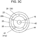
- FIG. 3C is a top view of another example of the rotation body of the motor according to the second exemplary embodiment of the present invention.
- dielectric layer 23 used in the motor of the second exemplary embodiment has dielectric bodies arranged in at least two layers along shaft center 42.
- FIG. 3A shows a rotation body from which the magnet has been removed to show outer core 25.
- Dielectric layer 23 is located between outer core 25 and inner core 26.
- dielectric layer 23 includes at least two layers along the shaft center.
- dielectric body 29 and dielectric body 30 are located in order of the top to bottom, respectively.
- Dielectric bodies 29 and 30 have different dielectric constants from each other.
- Dielectric bodies 29 and 30 have predetermined lengths along the shaft center.
- the dielectric constants are preferably as far from each other as possible. As the dielectric constants are more far from each other, the range of the capacitance of dielectric layer 23 becomes broader.
- dielectric 30 is larger in length than dielectric 29 along the shaft center. In this case, if dielectric 30 has a larger dielectric constant than that of dielectric 29, dielectric layer 23 has a maximum capacitance.
- dielectric layer 23 has a minimum capacitance.
- the dielectric constant of dielectric 29 and that of dielectric 30 are made quite different from each other.
- the capacitance of dielectric layer 23 with this property can be set to a desired value simply by making dielectric bodies 29 and 30 have different lengths in the direction along the shaft center. As described above, the settable range of the capacitance increases with increasing difference between the dielectric constants. This also facilitates the adjustment of the length ratio of dielectric 29 to dielectric 30 in order to obtain the desired capacitance.
- dielectric layer 23 includes dielectric bodies 29 and 30 arranged in two layers along shaft center 42. Obviously, however, the advantageous effects of the second exemplary embodiment can be obtained when the dielectric layer 23 includes dielectric bodies in the form of three or more layers.
- the dielectric bodies used in the motor according to the second exemplary embodiment may have holes penetrating them along the shaft center.
- dielectric layer 23 includes dielectric bodies 29 and 30.
- dielectric bodies 29 and 30 have holes 41, which penetrate them along shaft center 42. Holes 41 allow dielectric bodies 29 and 30 to accommodate the contraction of the insulating resins of which dielectric layer 23 is made, and also allow the adjustment of the capacitance between outer and inner cores 25 and 26.
- the dielectric bodies used in the motor according to the second exemplary embodiment may include recesses recessed into an inside of the dielectric bodies on their surface in the direction along the shaft center.
- recesses 41a may be provided instead of holes 41 shown in FIG. 3C .
- Recesses 41a are formed on surface 23a of the dielectric bodies along shaft center 42 so as to recess into an inside of the dielectric bodies. Similar to holes 41, recesses 41a allow dielectric bodies 29 and 30 to accommodate the contraction of the insulating resins of which they are made. Recesses 41a also allow internal dielectric body to adjust the capacitance between outer core 25 and inner core 26.
- FIG. 4A is a perspective view of a rotation body of an electric motor according to a third exemplary embodiment of the present invention.
- FIG. 4B is a sectional view of the rotation body of the motor according to the third exemplary embodiment of the present invention.
- FIG. 4C is a top view of another example of the rotation body of the motor according to the third exemplary embodiment of the present invention.
- dielectric layer 23 used in the motor according to the third exemplary embodiment of the present invention includes dielectric bodies 29 and 30 in the form of three or more layers.
- Dielectric layer 23 is located such that dielectric bodies 30 sandwich dielectric 29 along the shaft center as shown in FIGS. 4A and 4B .
- Rotation body 20 can be easily molded by disposing dielectric bodies 30 to sandwich dielectric 29 from above and below as in FIGS. 4A and 4B .
- dielectric layer 23 and magnet 22 is easily integrally molded to form rotation body 20.
- Magnet 22 can be, for example, a ferrite sintered magnet. A plurality of magnets 22 are fixed to rotation body 20.
- magnet 22 may become detached and fallen from rotation body 20.
- rotation body 20 is integrally molded with magnets 22.
- the integral molding of rotation body 20 can be easily performed in the following manner. First, dielectric 29, which has a predetermined length along shaft center 42, is sandwiched between outer and inner cores 25 and 26. Next, dielectric bodies 30 are molded integrally with magnets 22 fixed to outer core 25. With this procedure, dielectric layer 23 could have dielectric bodies 29 and 30 arranged in three or more layers along shaft center 42.
- the capacitance between outer and inner cores 25 and 26 can be changed as follows.
- the length ratio of dielectric 29 to dielectrics 30 adjacent to dielectric 29 along shaft center 42 can be adjusted, thereby obtaining a desired capacitance.
- the dielectric bodies used in the electric motor according to the third exemplary embodiment may have holes penetrating them along the shaft center.
- dielectric layer 23 includes dielectric bodies 29 and 30.
- dielectric bodies 29 and 30 have holes 41. Holes 41 penetrate dielectric bodies 29 and 30 along shaft center 42. Holes 41 allow dielectric bodies 29 and 30 to accommodate the contraction of the insulating resins of which dielectric layer 23 is made, and also allow the adjustment of the capacitance between outer and inner cores 25 and 26.
- the dielectric bodies used in the motor according to the third exemplary embodiment may include recesses on their surface along the shaft center so as to recess into an inside of the dielectric bodies.
- recesses 41a may be provided instead of holes 41 shown in FIG. 4C .
- Recesses 41a are formed on surface 23a of the dielectric bodies along shaft center 42 so as to recess into an inside of the dielectric bodies. Similar to holes 41, recesses 41a allow dielectric bodies 29 and 30 to accommodate the contraction of the insulating resins of which they are made. Recesses 41a also allow internal dielectric body to adjust the capacitance between outer core 25 and inner core 26.
- FIG. 5A is a perspective view of a rotation body of an electric motor according to a fourth exemplary embodiment of the present invention.
- FIG. 5B is a sectional view of the rotation body of the motor according to the fourth exemplary embodiment of the present invention.
- FIG. 5C is a top view of another example of the rotation body of the motor according to the fourth exemplary embodiment of the present invention.
- dielectric layer 23 used in the motor according to the fourth exemplary embodiment of the present invention is shorter in length along shaft center 42 than the shorter one of outer and inner cores 25 and 26.
- dielectric layer 23 is made shorter along shaft center than the shorter one of outer core 25 and inner core 26. More specifically, as shown in FIGS. 5A and 5B , the length of dielectric layer 23 is defined by dielectric bodies 29 and 30. The length of dielectric layer 23 corresponds to the total length of dielectric bodies 29 and 30 along the shaft. The length of dielectric layer 23 is shorter than either that of outer core 25 or that of inner core 26. Or, the length of dielectric layer 23 is shorter than both of outer core 25 and inner cores 26.
- the length of dielectric layer 23, which corresponds to the total length of dielectric bodies 29 and 30, is made shorter than the length of outer core 25 or the length of inner core 26 along shaft center 42.
- the dielectric layer made of the insulating resins is shorter than the rotor core formed of outer core 25 and inner core 26 along shaft center 42.
- an air layer is formed between outer core 25 and inner core 26 in place of dielectric layer 23 made of the insulating resins.
- air has a lower dielectric constant than insulating resins. Therefore, it is possible to adjust the position of the dielectric bodies in the space between cores 25 and 26 along shaft center 42. More specifically, the air layer has a higher proportion in dielectric layer 23. An increase in the proportion of the air layer in the space between outer core 25 and inner core 26 results in reducing the capacitance between outer core 25 and inner core 26.
- the dielectric bodies used in the motor according to the fourth exemplary embodiment have holes penetrating them along the shaft center.
- dielectric layer 23 includes dielectric bodies 29 and 30.
- dielectric bodies 29 and 30 have holes 41. Holes 41 penetrate dielectric bodies 29 and 30 along shaft center 42. Holes 41 allow dielectric bodies 29 and 30 to accommodate the contraction of the insulating resins of which dielectric layer 23 is made. Holes 41 also allow the adjustment of the capacitance between outer core 25 and inner core 26.
- the dielectric bodies used in the motor according to the fourth exemplary embodiment may include recesses on their surface along the shaft center.
- recesses 41a may be provided instead of holes 41 shown in FIG. 5C .
- Recesses 41a are formed on surface 23a of the dielectric bodies along shaft center 42 so as to recess into an inside of the dielectric bodies. Similar to holes 41, recesses 41a allow dielectric bodies 29 and 30 to accommodate the contraction of the insulating resins of which they are made. Recesses 41a also allow internal dielectric body to adjust the capacitance between outer core 25 and inner core 26.
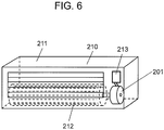
- FIG. 6 is a schematic diagram of the air-conditioning indoor unit including the motor of any one of the first to fourth exemplary embodiments of the present invention.
- air-conditioning indoor unit 210 which is the electrical device of the fifth exemplary embodiment of the present invention includes electric motor 201, and motor driving device 213, which is a drive section for driving electric motor 201.
- air-conditioning indoor unit 210 has housing 211 in which electric motor 201 is to be mounted.
- Electric motor 201 has a rotation shaft to which cross-flow fan 212 is to be attached.
- Housing 211 includes a heat exchanger.
- Electric motor 201 is driven by motor driving device 213, which is the drive section.
- Motor driving device 213 sends a drive signal to electric motor 201.
- Electric motor 201 is rotates according to the drive signal.
- Cross-flow fan 212 rotates as electric motor 201 rotates.
- Cross-flow fan 212 rotates to blow the air conditioned by the heat exchanger into a living room equipped with the air-conditioning indoor unit.
- the brushless motor described in the first to fourth exemplary embodiments can be used as electric motor 201.
- the air-conditioning indoor unit is shown as a specific example of the electrical device according to the fifth exemplary embodiment of the present invention.
- the above described specific example may be applied to the electric motor used for air-conditioning outdoor units and other various information and industrial devices.
- the fifth exemplary embodiment of the present invention has described a surface permanent-magnet motor in which the magnet is fixed to the outer core. It is also similarly effective to use an embedded permanent magnet motor in which a magnet is embedded in the outer core.
- the electric motor according to the exemplary embodiments of the present invention reduces occurrence of electric corrosion in the bearings by reducing the shaft voltage.
- the motor is suitable for use in electrical devices such as air-conditioning indoor and outdoor units that are expected to include a less expensive, longer-life motor.
Landscapes
- Engineering & Computer Science (AREA)
- Power Engineering (AREA)
- Microelectronics & Electronic Packaging (AREA)
- Motor Or Generator Frames (AREA)
- Iron Core Of Rotating Electric Machines (AREA)
- Insulation, Fastening Of Motor, Generator Windings (AREA)
Claims (8)
- Moteur électrique comprenant :un stator (10) comprenant un noyau de stator (11) autour duquel un enroulement (12) est enroulé ;un rotor (14) comprenant :une paire de paliers (15) supportant en rotation l'arbre ; etun corps de rotation (20) comprenant un aimant permanent s'étendant circonférentiellement et faisant face au stator, etun arbre (16) passant à travers un centre d'arbre du corps de rotation ;
une paire de supports (17, 24) fixant les paliers,
le corps de rotation comprenant en outre :un noyau en fer externe (25) situé dans un côté externe du corps de rotation ;un noyau en fer interne (26) fixé à l'arbre ; etune couche diélectrique (29, 30) située entre les noyaux en fer externe et interne ; etcaractérisé en ce que la couche diélectrique (29, 30) comprend au moins deux corps de constantes diélectriques différentes. - Moteur électrique de la revendication 1, dans lequel la couche diélectrique comprend les au moins deux corps diélectriques agencés dans au moins deux couches du centre d'arbre vers un côté extérieur du corps de rotation dans une direction orthogonale au centre d'arbre.
- Moteur électrique de la revendication 1, dans lequel la couche diélectrique comprend les corps diélectriques agencés dans au moins deux couches dans une direction suivant le centre d'arbre.
- Moteur électrique de la revendication 3, dans lequel
la couche diélectrique comprend les corps diélectriques agencés dans au moins trois couches dans la direction suivant le centre d'arbre ; et
les corps diélectriques situés aux deux extrémités dans la direction suivant le centre d'arbre ont une constante diélectrique identique. - Moteur diélectrique de l'une quelconque des revendications 1 à 3, dans lequel les corps diélectriques ont des trous pénétrant les corps diélectriques dans la direction suivant le centre d'arbre.
- Moteur diélectrique de l'une quelconque des revendications 1 à 3, dans lequel les corps diélectriques ont respectivement des évidements dans un intérieur des corps diélectriques sur des surfaces des corps diélectriques dans la direction suivant le centre d'arbre.
- Moteur diélectrique de l'une quelconque des revendications 1 à 3, dans lequel la couche diélectrique est de longueur plus courte dans la direction suivant le centre d'arbre qu'un plus court des noyaux en fer externe et interne.
- Dispositif électrique comprenant :le moteur électrique (201) de l'une quelconque des revendications 1 à 7 ; etune section d'entraînement (213) destinée à entraîner le moteur électrique.
Applications Claiming Priority (2)
| Application Number | Priority Date | Filing Date | Title |
|---|---|---|---|
| JP2013052844 | 2013-03-15 | ||
| PCT/JP2014/001281 WO2014141656A1 (fr) | 2013-03-15 | 2014-03-07 | Moteur électrique et dispositif électrique équipé du moteur électrique |
Publications (3)
| Publication Number | Publication Date |
|---|---|
| EP2975743A1 EP2975743A1 (fr) | 2016-01-20 |
| EP2975743A4 EP2975743A4 (fr) | 2016-05-04 |
| EP2975743B1 true EP2975743B1 (fr) | 2018-07-18 |
Family
ID=51536335
Family Applications (1)
| Application Number | Title | Priority Date | Filing Date |
|---|---|---|---|
| EP14762436.5A Active EP2975743B1 (fr) | 2013-03-15 | 2014-03-07 | Moteur électrique et dispositif électrique équipé du moteur électrique |
Country Status (5)
| Country | Link |
|---|---|
| US (1) | US9929617B2 (fr) |
| EP (1) | EP2975743B1 (fr) |
| JP (1) | JP6368917B2 (fr) |
| CN (1) | CN105103416B (fr) |
| WO (1) | WO2014141656A1 (fr) |
Families Citing this family (4)
| Publication number | Priority date | Publication date | Assignee | Title |
|---|---|---|---|---|
| EP2975743B1 (fr) * | 2013-03-15 | 2018-07-18 | Panasonic Intellectual Property Management Co., Ltd. | Moteur électrique et dispositif électrique équipé du moteur électrique |
| US9973840B2 (en) * | 2015-09-30 | 2018-05-15 | Apple Inc. | Waterproof receptacle connector |
| JP6332376B2 (ja) * | 2016-09-21 | 2018-05-30 | 株式会社富士通ゼネラル | 永久磁石電動機 |
| JP6855869B2 (ja) * | 2017-03-23 | 2021-04-07 | 株式会社富士通ゼネラル | 永久磁石電動機 |
Family Cites Families (22)
| Publication number | Priority date | Publication date | Assignee | Title |
|---|---|---|---|---|
| JPH0332333A (ja) * | 1989-06-26 | 1991-02-12 | Fanuc Ltd | ラジアルタイプのロータ構造 |
| US5704111A (en) * | 1995-05-24 | 1998-01-06 | General Electric Company | Method for making a rotor for an electric motor |
| US6121709A (en) * | 1997-10-16 | 2000-09-19 | Alliedsignal Inc. | Rotor assembly having bonded lamination stack |
| US6069421A (en) * | 1999-08-30 | 2000-05-30 | Electric Boat Corporation | Electric motor having composite encapsulated stator and rotor |
| JP2002110652A (ja) * | 2000-10-03 | 2002-04-12 | Rohm Co Ltd | プラズマ処理方法およびその装置 |
| GB0109847D0 (en) * | 2001-04-21 | 2001-06-13 | Johnson Electric Sa | Motor |
| DE10152497A1 (de) * | 2001-10-24 | 2003-05-15 | Pierburg Gmbh | Nassläuferpumpe |
| US7572115B2 (en) * | 2002-07-19 | 2009-08-11 | Innovative Mag-Drive, Llc | Corrosion-resistant rotor for a magnetic-drive centrifugal pump |
| US20050253480A1 (en) * | 2004-05-14 | 2005-11-17 | Pizzichil William P | Apparatus and method for reducing shaft charge |
| JP2007165755A (ja) * | 2005-12-16 | 2007-06-28 | Matsushita Electric Ind Co Ltd | 配線基板およびその製造方法 |
| JP4912752B2 (ja) * | 2006-05-30 | 2012-04-11 | 日本電産テクノモータホールディングス株式会社 | モータ |
| EP2254220B1 (fr) * | 2008-03-13 | 2017-03-01 | Panasonic Intellectual Property Management Co., Ltd. | Moteur électrique et machine électrique équipée de celui-ci |
| EP2378644B1 (fr) * | 2009-02-26 | 2016-12-28 | Panasonic Intellectual Property Management Co., Ltd. | Moteur et équipement électrique équipé de celui-ci |
| WO2011030536A1 (fr) * | 2009-09-10 | 2011-03-17 | パナソニック株式会社 | Moteur électrique et dispositif électrique comportant ce moteur |
| CN102884716B (zh) * | 2010-05-12 | 2015-08-19 | 松下电器产业株式会社 | 电动马达和包括该电动马达的电动装置 |
| US9035503B2 (en) * | 2011-01-12 | 2015-05-19 | Kollmorgen Corporation | Environmentally protected housingless generator/motor |
| WO2012105193A1 (fr) * | 2011-02-01 | 2012-08-09 | パナソニック株式会社 | Moteur moulé |
| JP2012239368A (ja) | 2011-04-27 | 2012-12-06 | Panasonic Corp | 電動機およびそれを備えた電気機器 |
| US9071090B2 (en) * | 2011-04-27 | 2015-06-30 | Panasonic Intellectual Property Management Co., Ltd. | Motor and electric device including the same |
| JP2014018020A (ja) * | 2012-07-11 | 2014-01-30 | Panasonic Corp | 電動機およびそれを備えた電気機器 |
| EP2975743B1 (fr) * | 2013-03-15 | 2018-07-18 | Panasonic Intellectual Property Management Co., Ltd. | Moteur électrique et dispositif électrique équipé du moteur électrique |
| CN105659478B (zh) * | 2013-10-21 | 2019-03-29 | 松下知识产权经营株式会社 | 电动机以及具备该电动机的电设备 |
-
2014
- 2014-03-07 EP EP14762436.5A patent/EP2975743B1/fr active Active
- 2014-03-07 US US14/773,754 patent/US9929617B2/en active Active
- 2014-03-07 JP JP2015505275A patent/JP6368917B2/ja active Active
- 2014-03-07 CN CN201480016139.3A patent/CN105103416B/zh active Active
- 2014-03-07 WO PCT/JP2014/001281 patent/WO2014141656A1/fr not_active Ceased
Non-Patent Citations (1)
| Title |
|---|
| None * |
Also Published As
| Publication number | Publication date |
|---|---|
| WO2014141656A1 (fr) | 2014-09-18 |
| US9929617B2 (en) | 2018-03-27 |
| EP2975743A1 (fr) | 2016-01-20 |
| CN105103416A (zh) | 2015-11-25 |
| EP2975743A4 (fr) | 2016-05-04 |
| JPWO2014141656A1 (ja) | 2017-02-16 |
| CN105103416B (zh) | 2018-06-19 |
| JP6368917B2 (ja) | 2018-08-08 |
| US20160028289A1 (en) | 2016-01-28 |
Similar Documents
| Publication | Publication Date | Title |
|---|---|---|
| CN205029472U (zh) | 电动机以及具备该电动机的电气设备 | |
| JP6208333B2 (ja) | アキシャルギャップ型回転電機 | |
| CN105659478B (zh) | 电动机以及具备该电动机的电设备 | |
| EP2697891B1 (fr) | Enroulement souple pour un moteur électrique et son procédé de fabrication | |
| JP2012249522A (ja) | 電動機およびそれを備えた電気機器 | |
| EP2975743B1 (fr) | Moteur électrique et dispositif électrique équipé du moteur électrique | |
| US9059615B2 (en) | Motor and electric apparatus equipped with same | |
| JP5370431B2 (ja) | 電動機およびそれを備えた電気機器 | |
| CN105048665A (zh) | 无刷电机 | |
| EP3598616A1 (fr) | Système de moteur électrique et turbocompresseur équipé de celui-ci | |
| CN103339837A (zh) | 模制电动机 | |
| JP2014107998A (ja) | 電動機 | |
| CN102474152A (zh) | 空气调节机 | |
| JP2015023750A (ja) | 電動機 | |
| JP2015512241A (ja) | 電気機械 | |
| JP2011205724A (ja) | 空気調和機 | |
| JP2015056970A (ja) | 電気機器 | |
| CN102648571B (zh) | Hvac风机的空心线圈绕组 | |
| JP5312521B2 (ja) | 電動機および空調機 | |
| JP5493931B2 (ja) | 空気調和機 | |
| JP2014147241A (ja) | 電動機およびそれを備えた電気機器 | |
| KR20140145996A (ko) | 전기 모터 | |
| JP5312519B2 (ja) | 電動機および空調機 | |
| JP2012244777A (ja) | 電動機および空調機 | |
| JP2021052568A (ja) | 電動機 |
Legal Events
| Date | Code | Title | Description |
|---|---|---|---|
| PUAI | Public reference made under article 153(3) epc to a published international application that has entered the european phase |
Free format text: ORIGINAL CODE: 0009012 |
|
| 17P | Request for examination filed |
Effective date: 20150819 |
|
| AK | Designated contracting states |
Kind code of ref document: A1 Designated state(s): AL AT BE BG CH CY CZ DE DK EE ES FI FR GB GR HR HU IE IS IT LI LT LU LV MC MK MT NL NO PL PT RO RS SE SI SK SM TR |
|
| AX | Request for extension of the european patent |
Extension state: BA ME |
|
| A4 | Supplementary search report drawn up and despatched |
Effective date: 20160406 |
|
| RIC1 | Information provided on ipc code assigned before grant |
Ipc: H02K 5/173 20060101ALI20160331BHEP Ipc: H02K 5/16 20060101ALI20160331BHEP Ipc: H02K 1/27 20060101ALI20160331BHEP Ipc: H02K 1/28 20060101ALI20160331BHEP Ipc: H02K 11/00 20160101AFI20160331BHEP Ipc: H02K 1/30 20060101ALI20160331BHEP |
|
| DAX | Request for extension of the european patent (deleted) | ||
| STAA | Information on the status of an ep patent application or granted ep patent |
Free format text: STATUS: EXAMINATION IS IN PROGRESS |
|
| 17Q | First examination report despatched |
Effective date: 20170712 |
|
| GRAP | Despatch of communication of intention to grant a patent |
Free format text: ORIGINAL CODE: EPIDOSNIGR1 |
|
| STAA | Information on the status of an ep patent application or granted ep patent |
Free format text: STATUS: GRANT OF PATENT IS INTENDED |
|
| INTG | Intention to grant announced |
Effective date: 20180430 |
|
| GRAS | Grant fee paid |
Free format text: ORIGINAL CODE: EPIDOSNIGR3 |
|
| GRAA | (expected) grant |
Free format text: ORIGINAL CODE: 0009210 |
|
| STAA | Information on the status of an ep patent application or granted ep patent |
Free format text: STATUS: THE PATENT HAS BEEN GRANTED |
|
| AK | Designated contracting states |
Kind code of ref document: B1 Designated state(s): AL AT BE BG CH CY CZ DE DK EE ES FI FR GB GR HR HU IE IS IT LI LT LU LV MC MK MT NL NO PL PT RO RS SE SI SK SM TR |
|
| REG | Reference to a national code |
Ref country code: GB Ref legal event code: FG4D |
|
| REG | Reference to a national code |
Ref country code: CH Ref legal event code: EP |
|
| REG | Reference to a national code |
Ref country code: IE Ref legal event code: FG4D |
|
| REG | Reference to a national code |
Ref country code: AT Ref legal event code: REF Ref document number: 1020413 Country of ref document: AT Kind code of ref document: T Effective date: 20180815 |
|
| REG | Reference to a national code |
Ref country code: DE Ref legal event code: R096 Ref document number: 602014028748 Country of ref document: DE |
|
| REG | Reference to a national code |
Ref country code: NL Ref legal event code: MP Effective date: 20180718 |
|
| REG | Reference to a national code |
Ref country code: LT Ref legal event code: MG4D |
|
| REG | Reference to a national code |
Ref country code: AT Ref legal event code: MK05 Ref document number: 1020413 Country of ref document: AT Kind code of ref document: T Effective date: 20180718 |
|
| PG25 | Lapsed in a contracting state [announced via postgrant information from national office to epo] |
Ref country code: NL Free format text: LAPSE BECAUSE OF FAILURE TO SUBMIT A TRANSLATION OF THE DESCRIPTION OR TO PAY THE FEE WITHIN THE PRESCRIBED TIME-LIMIT Effective date: 20180718 |
|
| PG25 | Lapsed in a contracting state [announced via postgrant information from national office to epo] |
Ref country code: GR Free format text: LAPSE BECAUSE OF FAILURE TO SUBMIT A TRANSLATION OF THE DESCRIPTION OR TO PAY THE FEE WITHIN THE PRESCRIBED TIME-LIMIT Effective date: 20181019 Ref country code: FI Free format text: LAPSE BECAUSE OF FAILURE TO SUBMIT A TRANSLATION OF THE DESCRIPTION OR TO PAY THE FEE WITHIN THE PRESCRIBED TIME-LIMIT Effective date: 20180718 Ref country code: SE Free format text: LAPSE BECAUSE OF FAILURE TO SUBMIT A TRANSLATION OF THE DESCRIPTION OR TO PAY THE FEE WITHIN THE PRESCRIBED TIME-LIMIT Effective date: 20180718 Ref country code: LT Free format text: LAPSE BECAUSE OF FAILURE TO SUBMIT A TRANSLATION OF THE DESCRIPTION OR TO PAY THE FEE WITHIN THE PRESCRIBED TIME-LIMIT Effective date: 20180718 Ref country code: PL Free format text: LAPSE BECAUSE OF FAILURE TO SUBMIT A TRANSLATION OF THE DESCRIPTION OR TO PAY THE FEE WITHIN THE PRESCRIBED TIME-LIMIT Effective date: 20180718 Ref country code: IS Free format text: LAPSE BECAUSE OF FAILURE TO SUBMIT A TRANSLATION OF THE DESCRIPTION OR TO PAY THE FEE WITHIN THE PRESCRIBED TIME-LIMIT Effective date: 20181118 Ref country code: RS Free format text: LAPSE BECAUSE OF FAILURE TO SUBMIT A TRANSLATION OF THE DESCRIPTION OR TO PAY THE FEE WITHIN THE PRESCRIBED TIME-LIMIT Effective date: 20180718 Ref country code: NO Free format text: LAPSE BECAUSE OF FAILURE TO SUBMIT A TRANSLATION OF THE DESCRIPTION OR TO PAY THE FEE WITHIN THE PRESCRIBED TIME-LIMIT Effective date: 20181018 Ref country code: AT Free format text: LAPSE BECAUSE OF FAILURE TO SUBMIT A TRANSLATION OF THE DESCRIPTION OR TO PAY THE FEE WITHIN THE PRESCRIBED TIME-LIMIT Effective date: 20180718 Ref country code: BG Free format text: LAPSE BECAUSE OF FAILURE TO SUBMIT A TRANSLATION OF THE DESCRIPTION OR TO PAY THE FEE WITHIN THE PRESCRIBED TIME-LIMIT Effective date: 20181018 |
|
| PG25 | Lapsed in a contracting state [announced via postgrant information from national office to epo] |
Ref country code: AL Free format text: LAPSE BECAUSE OF FAILURE TO SUBMIT A TRANSLATION OF THE DESCRIPTION OR TO PAY THE FEE WITHIN THE PRESCRIBED TIME-LIMIT Effective date: 20180718 Ref country code: HR Free format text: LAPSE BECAUSE OF FAILURE TO SUBMIT A TRANSLATION OF THE DESCRIPTION OR TO PAY THE FEE WITHIN THE PRESCRIBED TIME-LIMIT Effective date: 20180718 Ref country code: LV Free format text: LAPSE BECAUSE OF FAILURE TO SUBMIT A TRANSLATION OF THE DESCRIPTION OR TO PAY THE FEE WITHIN THE PRESCRIBED TIME-LIMIT Effective date: 20180718 |
|
| REG | Reference to a national code |
Ref country code: DE Ref legal event code: R097 Ref document number: 602014028748 Country of ref document: DE |
|
| PG25 | Lapsed in a contracting state [announced via postgrant information from national office to epo] |
Ref country code: EE Free format text: LAPSE BECAUSE OF FAILURE TO SUBMIT A TRANSLATION OF THE DESCRIPTION OR TO PAY THE FEE WITHIN THE PRESCRIBED TIME-LIMIT Effective date: 20180718 Ref country code: ES Free format text: LAPSE BECAUSE OF FAILURE TO SUBMIT A TRANSLATION OF THE DESCRIPTION OR TO PAY THE FEE WITHIN THE PRESCRIBED TIME-LIMIT Effective date: 20180718 Ref country code: RO Free format text: LAPSE BECAUSE OF FAILURE TO SUBMIT A TRANSLATION OF THE DESCRIPTION OR TO PAY THE FEE WITHIN THE PRESCRIBED TIME-LIMIT Effective date: 20180718 Ref country code: CZ Free format text: LAPSE BECAUSE OF FAILURE TO SUBMIT A TRANSLATION OF THE DESCRIPTION OR TO PAY THE FEE WITHIN THE PRESCRIBED TIME-LIMIT Effective date: 20180718 Ref country code: IT Free format text: LAPSE BECAUSE OF FAILURE TO SUBMIT A TRANSLATION OF THE DESCRIPTION OR TO PAY THE FEE WITHIN THE PRESCRIBED TIME-LIMIT Effective date: 20180718 |
|
| PLBE | No opposition filed within time limit |
Free format text: ORIGINAL CODE: 0009261 |
|
| STAA | Information on the status of an ep patent application or granted ep patent |
Free format text: STATUS: NO OPPOSITION FILED WITHIN TIME LIMIT |
|
| PG25 | Lapsed in a contracting state [announced via postgrant information from national office to epo] |
Ref country code: SM Free format text: LAPSE BECAUSE OF FAILURE TO SUBMIT A TRANSLATION OF THE DESCRIPTION OR TO PAY THE FEE WITHIN THE PRESCRIBED TIME-LIMIT Effective date: 20180718 Ref country code: DK Free format text: LAPSE BECAUSE OF FAILURE TO SUBMIT A TRANSLATION OF THE DESCRIPTION OR TO PAY THE FEE WITHIN THE PRESCRIBED TIME-LIMIT Effective date: 20180718 Ref country code: SK Free format text: LAPSE BECAUSE OF FAILURE TO SUBMIT A TRANSLATION OF THE DESCRIPTION OR TO PAY THE FEE WITHIN THE PRESCRIBED TIME-LIMIT Effective date: 20180718 |
|
| 26N | No opposition filed |
Effective date: 20190423 |
|
| PG25 | Lapsed in a contracting state [announced via postgrant information from national office to epo] |
Ref country code: SI Free format text: LAPSE BECAUSE OF FAILURE TO SUBMIT A TRANSLATION OF THE DESCRIPTION OR TO PAY THE FEE WITHIN THE PRESCRIBED TIME-LIMIT Effective date: 20180718 |
|
| PG25 | Lapsed in a contracting state [announced via postgrant information from national office to epo] |
Ref country code: MC Free format text: LAPSE BECAUSE OF FAILURE TO SUBMIT A TRANSLATION OF THE DESCRIPTION OR TO PAY THE FEE WITHIN THE PRESCRIBED TIME-LIMIT Effective date: 20180718 |
|
| REG | Reference to a national code |
Ref country code: CH Ref legal event code: PL |
|
| GBPC | Gb: european patent ceased through non-payment of renewal fee |
Effective date: 20190307 |
|
| PG25 | Lapsed in a contracting state [announced via postgrant information from national office to epo] |
Ref country code: LU Free format text: LAPSE BECAUSE OF NON-PAYMENT OF DUE FEES Effective date: 20190307 |
|
| REG | Reference to a national code |
Ref country code: BE Ref legal event code: MM Effective date: 20190331 |
|
| PG25 | Lapsed in a contracting state [announced via postgrant information from national office to epo] |
Ref country code: CH Free format text: LAPSE BECAUSE OF NON-PAYMENT OF DUE FEES Effective date: 20190331 Ref country code: IE Free format text: LAPSE BECAUSE OF NON-PAYMENT OF DUE FEES Effective date: 20190307 Ref country code: GB Free format text: LAPSE BECAUSE OF NON-PAYMENT OF DUE FEES Effective date: 20190307 Ref country code: LI Free format text: LAPSE BECAUSE OF NON-PAYMENT OF DUE FEES Effective date: 20190331 |
|
| PG25 | Lapsed in a contracting state [announced via postgrant information from national office to epo] |
Ref country code: BE Free format text: LAPSE BECAUSE OF NON-PAYMENT OF DUE FEES Effective date: 20190331 Ref country code: FR Free format text: LAPSE BECAUSE OF NON-PAYMENT OF DUE FEES Effective date: 20190331 |
|
| PG25 | Lapsed in a contracting state [announced via postgrant information from national office to epo] |
Ref country code: TR Free format text: LAPSE BECAUSE OF FAILURE TO SUBMIT A TRANSLATION OF THE DESCRIPTION OR TO PAY THE FEE WITHIN THE PRESCRIBED TIME-LIMIT Effective date: 20180718 |
|
| PG25 | Lapsed in a contracting state [announced via postgrant information from national office to epo] |
Ref country code: MT Free format text: LAPSE BECAUSE OF NON-PAYMENT OF DUE FEES Effective date: 20190307 Ref country code: PT Free format text: LAPSE BECAUSE OF FAILURE TO SUBMIT A TRANSLATION OF THE DESCRIPTION OR TO PAY THE FEE WITHIN THE PRESCRIBED TIME-LIMIT Effective date: 20181118 |
|
| PG25 | Lapsed in a contracting state [announced via postgrant information from national office to epo] |
Ref country code: CY Free format text: LAPSE BECAUSE OF FAILURE TO SUBMIT A TRANSLATION OF THE DESCRIPTION OR TO PAY THE FEE WITHIN THE PRESCRIBED TIME-LIMIT Effective date: 20180718 |
|
| PG25 | Lapsed in a contracting state [announced via postgrant information from national office to epo] |
Ref country code: HU Free format text: LAPSE BECAUSE OF FAILURE TO SUBMIT A TRANSLATION OF THE DESCRIPTION OR TO PAY THE FEE WITHIN THE PRESCRIBED TIME-LIMIT; INVALID AB INITIO Effective date: 20140307 |
|
| PG25 | Lapsed in a contracting state [announced via postgrant information from national office to epo] |
Ref country code: MK Free format text: LAPSE BECAUSE OF FAILURE TO SUBMIT A TRANSLATION OF THE DESCRIPTION OR TO PAY THE FEE WITHIN THE PRESCRIBED TIME-LIMIT Effective date: 20180718 |
|
| PGFP | Annual fee paid to national office [announced via postgrant information from national office to epo] |
Ref country code: DE Payment date: 20260319 Year of fee payment: 13 |