EP2976126B1 - Mikronadelauftragselement mit einer zähleranordnung - Google Patents
Mikronadelauftragselement mit einer zähleranordnung Download PDFInfo
- Publication number
- EP2976126B1 EP2976126B1 EP14720014.1A EP14720014A EP2976126B1 EP 2976126 B1 EP2976126 B1 EP 2976126B1 EP 14720014 A EP14720014 A EP 14720014A EP 2976126 B1 EP2976126 B1 EP 2976126B1
- Authority
- EP
- European Patent Office
- Prior art keywords
- microneedle array
- microneedle
- housing
- applicator
- holder
- Prior art date
- Legal status (The legal status is an assumption and is not a legal conclusion. Google has not performed a legal analysis and makes no representation as to the accuracy of the status listed.)
- Active
Links
Images


Classifications
-
- A—HUMAN NECESSITIES
- A61—MEDICAL OR VETERINARY SCIENCE; HYGIENE
- A61M—DEVICES FOR INTRODUCING MEDIA INTO, OR ONTO, THE BODY; DEVICES FOR TRANSDUCING BODY MEDIA OR FOR TAKING MEDIA FROM THE BODY; DEVICES FOR PRODUCING OR ENDING SLEEP OR STUPOR
- A61M37/00—Other apparatus for introducing media into the body; Percutany, i.e. introducing medicines into the body by diffusion through the skin
- A61M37/0015—Other apparatus for introducing media into the body; Percutany, i.e. introducing medicines into the body by diffusion through the skin by using microneedles
- A61M2037/0023—Drug applicators using microneedles
-
- A—HUMAN NECESSITIES
- A61—MEDICAL OR VETERINARY SCIENCE; HYGIENE
- A61M—DEVICES FOR INTRODUCING MEDIA INTO, OR ONTO, THE BODY; DEVICES FOR TRANSDUCING BODY MEDIA OR FOR TAKING MEDIA FROM THE BODY; DEVICES FOR PRODUCING OR ENDING SLEEP OR STUPOR
- A61M37/00—Other apparatus for introducing media into the body; Percutany, i.e. introducing medicines into the body by diffusion through the skin
- A61M37/0015—Other apparatus for introducing media into the body; Percutany, i.e. introducing medicines into the body by diffusion through the skin by using microneedles
- A61M2037/003—Other apparatus for introducing media into the body; Percutany, i.e. introducing medicines into the body by diffusion through the skin by using microneedles having a lumen
-
- A—HUMAN NECESSITIES
- A61—MEDICAL OR VETERINARY SCIENCE; HYGIENE
- A61M—DEVICES FOR INTRODUCING MEDIA INTO, OR ONTO, THE BODY; DEVICES FOR TRANSDUCING BODY MEDIA OR FOR TAKING MEDIA FROM THE BODY; DEVICES FOR PRODUCING OR ENDING SLEEP OR STUPOR
- A61M37/00—Other apparatus for introducing media into the body; Percutany, i.e. introducing medicines into the body by diffusion through the skin
- A61M37/0015—Other apparatus for introducing media into the body; Percutany, i.e. introducing medicines into the body by diffusion through the skin by using microneedles
- A61M2037/0046—Solid microneedles
-
- A—HUMAN NECESSITIES
- A61—MEDICAL OR VETERINARY SCIENCE; HYGIENE
- A61M—DEVICES FOR INTRODUCING MEDIA INTO, OR ONTO, THE BODY; DEVICES FOR TRANSDUCING BODY MEDIA OR FOR TAKING MEDIA FROM THE BODY; DEVICES FOR PRODUCING OR ENDING SLEEP OR STUPOR
- A61M2205/00—General characteristics of the apparatus
- A61M2205/60—General characteristics of the apparatus with identification means
Definitions
- the present disclosure generally relates to microneedle applicators and methods for applying a microneedle applicator to skin to treat an area of the skin and/or deliver an active agent to the skin.
- Transdermal and topical drug delivery can be used for therapeutic treatment, but the number of molecules that can be effectively delivered using these routes can be limited by the barrier properties of skin.
- the main barrier to the transport of molecules through the skin is the stratum corneum (the outermost layer of the skin).
- the stratum corneum is a complex structure of compact keratinized cell remnants separated by lipid domains.
- the stratum corneum is formed of keratinocytes, which make up the majority of epidermal cells, that lose their nuclei and become corneocytes. These dead cells comprise the stratum corneum, which has a thickness of only about 10-30 microns and protects the body from invasion by exogenous substances and the outward migration of endogenous fluids and dissolved molecules.
- Various skin treatment methods include the use of microneedles, laser ablation, RF ablation, heat ablation, sonophoresis, iontophoresis, or a combination thereof.
- Microneedle or micro-pin arrays also sometimes referred to as microstructured transdermal Systems (MTSs)
- MTSs microstructured transdermal Systems
- the sharp microneedle tip is designed to be able to penetrate the stratum corneum layer of the skin, but short enough not to puncture nerve endings, thus reducing or eliminating pain upon insertion.
- the penetration of microneedles to precise levels within the skin tissue and with good reproducibility is often a challenging task. Therefore, unlike the application of traditional patch-based delivery systems, some existing MTSs require the assistance of external energy to ensure efficient and reproducible penetration of microneedles into biological tissue at desired depths.
- This assistance can be achieved by utilizing an applicator device, which can either be used after positioning the microneedle array on the skin surface, or the applicator device can be integrated with an array of microneedles and, upon activation, can deliver the microneedle array into the skin.
- the microneedles help to create microchannels in the skin, which in some embodiments, can facilitate delivering an active ingredient.
- an active ingredient can be applied subsequent to perforating the skin with the microneedles.
- active component(s) may be coated on the microneedle array and delivered directly through the skin when the stratum corneum is punctured by the microneedles.
- Late published document WO 2014110016 (published 17.07.2014 , US priority 08.01.2013) relates to an applicator for applying a microneedle device.
- the applicator comprises a housing having a first open end configured so as to accept the microneedle device, a second end configured as a graspable handle, a driving element contained within the housing, the driving element having a first end configured so as to couple with the microneedle device, an actuation button in mechanical or electrical engagement with the driving element, at least one reciprocating support structure slidably engaged with the housing, wherein the reciprocating support structure has a first position where at least a portion of it extends from the first open end of the housing by a first distance and a second position wherein the portion extends from the first open end of the housing by a second distance, the second distance being less than the first distance.
- microneedle applicators that provide safety assurance and ease-of-use, particularly to an unskilled or naive user (e.g., a consumer), such as to minimize the damage to a user's skin; to limit the maximum amount of force that can be applied (and depth of penetration that can be achieved) via the microneedle array; and to prevent unintentional application, e.g., due to premature or unintentional exposure of the microneedle array.
- the present disclosure is generally directed to microneedle applicators comprising a counter assembly that can count the number of times a microneedle array (or microneedle array holder) has been moved to an extended position. That is, the counter assemblies of applicators of the present disclosure can be used to count the number of times a specific microneedle array has been used, and can indicate the number to a user, signifying to the user when to change the microneedle array. Such a counter assembly can automatically perform the count as the applicator is used, which can enhance user compliance and ensure that only simple user instructions are needed to operate the applicator correctly and safely.
- the present invention relates to a microneedle applicator comprising a housing having a base and an opening formed in the base, wherein the base of the housing is configured to be positioned on a skin surface; and a microneedle array holder configured to hold a microneedle array.
- the applicator can further include an actuator movable with respect to the housing between a first position and a second position to cause the microneedle array holder to move, respectively, between (i) a retracted position in which the microneedle array is recessed within the housing such that the microneedle array does not contact the skin surface when the base of the housing is positioned on the skin surface and the microneedle array is coupled to the microneedle array holder, and (ii) an extended position in which at least a portion of the microneedle array is positioned to contact the skin surface when the base of the housing is positioned on the skin surface and the microneedle array is coupled to the microneedle array holder.
- the applicator can further include a first biasing element configured to bias the actuator in the first position; and a counter assembly configured to count a number of times the microneedle array holder is moved between the retracted position and the extended position.
- applicators of the present disclosure can provide force dampening when a user attempts to apply a microneedle array onto a substrate that exceeds a threshold (i.e., maximum) application force.
- a threshold i.e., maximum
- applicators of the present disclosure include a dampening element allows the microneedle array to retract away from the substrate when the threshold application force is met or exceeded.
- the applicators can also control the depth of penetration that is achieved with the microneedles.
- applicators of the present disclosure can provide safety and ease-of-use, particularly to an unskilled or naive user (e.g., a consumer), and can minimize premature or unintentional exposure to, or penetration by, the microneedle array.
- the applicator can include a cover that can protect a microneedle array located inside the applicator and can limit premature or unintentional exposure of the microneedle array.
- Such a cover can also be movable with respect to an actuation axis (e.g., to an "off-axis" position), to provide clearance for loading a microneedle array into the applicator and to prevent unintentional application, e.g., due to premature or unintentional exposure of the microneedle array.
- an actuation axis e.g., to an "off-axis" position
- Some embodiments of the present disclosure provide applicators that can include one or more of: (i) a cover positioned to limit exposure to a microneedle array coupled to (or located inside) the applicator while allowing the cover to be (re)movable to an off-axis position (e.g., to facilitate microneedle array loading); (ii) means for limiting the amount of force that can be applied to the skin via the microneedle array, and (iii) a counter mechanism for counting (and optionally displaying or indicating) the number of times a microneedle array coupled to the applicator has been used.
- microneedle array While typically unnecessary or even undesirable in the field of pharmaceuticals or transdermal drug delivery, in some fields and applications, it may be possible or even necessary to reuse the same microneedle array. For example, in cosmetic applications, it may be necessary to treat a desired surface area of skin, such as a contoured surface of a face.
- Some microneedle designs allow for repeat use, particularly, if repeat use will not negatively affect accurate drug dosing, e.g., in applications where the microneedles are used to perforate skin prior to a topical application of a desired substance. However, most microneedles cannot be repeatedly used to puncture or perforate skin indefinitely, and the microneedles will eventually dull. The number of uses may vary depending on the makeup and configuration of the microneedles.
- the applicators of the present disclosure generally provide applicators comprising a counter mechanism or assembly that allow the same microneedle array to be reused, while counting the number of uses to adequately notify a user when a maximum number of uses has been met. At that point, the user can exchange the microneedle array for a fresh, unused array.
- Some embodiments of the present disclosure employ simple, robust, mechanical counter assemblies that allow some of the same components that drive the actuation of the applicator to serve a dual function of also driving the counter mechanism.
- Such robust applicators can be relatively inexpensive to manufacture and can allow for counters to be employed in the applicators with a minimal number of additional componentry and without requiring on-board electronics. Such features can be particularly advantageous for consumer-based applications.
- Some aspects of the present disclosure can provide microneedle applicators that allow the microneedle array, and particularly, a microneedle array holder configured to hold and move the microneedle array, to retract away from a substrate (e.g., a skin surface) to which the microneedle array is being applied by employing a dampening element.
- a dampening element can include a biasing element that biases the microneedle array holder in an extended position, but which allows the microneedle array holder to be moved to a dampened position against the bias of the biasing element when a threshold (i.e., maximum) application force is applied to the microneedle array.
- Such an application force ultimately will be 'felt' by the applicator as a result of the skin pressing back on the microneedle array (e.g., in a direction generally normal to the skin surface and/or normal to a first skin-facing side of the microneedle array or microneedle array holder); however, the source of the force comes from a user pressing (e.g., over-pressing) the microneedle applicator onto the skin.
- some aspects of the present disclosure can provide a microneedle applicator comprising a cover that is movable with respect to an actuation axis to provide clearance for loading a microneedle array onto a microneedle array holder.
- the cover can be returned to its initial position where it can at least partially house the microneedle array prior to actuation (i.e., delivery of the microneedle array to a desired substrate, e.g., a skin surface).
- the cover can include a base configured to be positioned on a skin surface and an opening formed in the base through which the microneedle array can pass, e.g., along an "actuation axis" when the applicator is actuated to deliver the microneedle array (i.e., to puncture or perforate skin with the microneedle array).
- the actuation axis can be oriented substantially normal to a surface to which the microneedle array is to be applied, and can also be substantially normal to the base of the cover (or a tangent thereof).
- the cover can also be movable to a position (i.e., an "off-axis position") where the actuation axis no longer passes through the opening in the cover, and the microneedle array holder is more exposed, e.g., to facilitate loading a microneedle array onto the holder.
- Microneedle applicators of the present disclosure are particularly suitable for consumer-based applications where the applicator will be operated primarily by naive or unskilled users, as opposed to medical practitioners. Such microneedle applicators are intuitively shaped and designed to convey to a user how the applicator should be operated.
- the applicator can be elongated along the actuation axis (i.e., the actuation axis can also be, or be parallel to, the longitudinal axis of the applicator), clearly conveying to a user that the applicator is configured to stamp a microneedle array toward the skin surface, as opposed to using the applicator to scrape or drag a microneedle array along the skin surface.
- the counter assembly also provides an unskilled user with a count of the number of times a microneedle array has been used to avoid unsafe or ineffective microneedle array application, and to signify to a user when to change the microneedle array.
- applicators and microneedle arrays are designed to be left in place on the skin, continuing to puncture the skin and/or deliver an active agent, the applicators of the present disclosure are designed to allow the microneedles to puncture the skin up to a desired force and to a desired depth, but are generally not designed to be left on the skin for an extended treatment period.
- Applicators of the present disclosure may be useful when applied to the skin as a "pretreatment" step, that is, when applied to the skin to disrupt the stratum corneum layer of skin and then removed.
- the disrupted area of skin may then be useful for allowing enhanced delivery of a topical composition (e.g., a solution, a cream, a lotion, a gel, an ointment, or the like) or patch comprising an active agent that is applied to the disrupted area.
- Applicators of the present disclosure may also be useful when the microneedles are provided with a dried coating comprising an active agent that dissolves from the microneedles after they are inserted into the skin.
- applicators of the present disclosure may have utility for enhancing delivery of molecules to the skin, such as in dermatological treatments, vaccine delivery, or in enhancing immune response of vaccine adjuvants.
- the active agent may be applied to the skin (e.g., in the form of a solution that is swabbed onto the skin surface, or as a cream, lotion, gel, ointment, or the like, that is rubbed into the skin surface) prior to applying the microneedles of the applicators of the present disclosure.
- the patch When a patch is applied to the treated or disrupted site, the patch can be provided in a variety of forms and can include a drug reservoir comprising an active agent for delivery to the treated site.
- Any transdermal patch suitable for the continuous transdermal delivery of a therapeutically effective amount of an appropriate medicament may be used.
- Suitable transdermal patches include gelled or liquid reservoirs, such as in U.S. Patent No. 4,834,979 (Gale ), so-called “reservoir” patches; patches containing matrix reservoirs attached to the skin by an adjacent adhesive layer, such as in U.S. Patent No. 6,004,578 (Lee et al. ), so-called “matrix” patches; and patches containing pressure-sensitive adhesive (PSA) reservoirs, such as in U.S.
- PSA pressure-sensitive adhesive
- the drug reservoir can be provided in the form of a matrix layer containing drug, the matrix layer being adhered to a skin-contact adhesive of the patch.
- a matrix may be an adhesive layer.
- the matrix layer may be non-adhesive or weakly adhesive and rely upon the surrounding rim of skin-contact adhesive on an adhesive patch to secure the patch in place and keep the drug reservoir in contact with the skin surface.
- the drug reservoir can be provided in the form of solid particles embedded on the surface or within the skin-contact adhesive of the patch.
- these particles may be hydrophilic, so that contact with aqueous fluid exposed at the surface of the treated skin will cause them to dissolve or disintegrate, thus releasing drug into the skin.
- the drug reservoir can be provided within the skin-contact adhesive of the patch.
- the drug may be mixed with the skin-contact adhesive prior to forming the patch or it may be applied to the skin-contact adhesive of the patch in a separate process step. Examples of suitable methods for applying drug to an adhesive layer may be found in U.S. Patent Application Publication No. 2003/054025 (Cantor et al. ) and U.S. Patent No. 5,688,523 (Garbe et al. ).
- the length of time between (i) treatment of the skin with microneedles to increase permeability and (ii) placement of the active agent in contact with the treated skin area may vary. In some embodiments, this length of time can be kept to a minimum in order to avoid any possibility of the skin barrier reforming through a healing process.
- the minimum length of time can be generally governed by the time it takes to remove the applicators of the present disclosure from the skin and apply the active agent, for example, by swapping on a solution, rubbing in a cream or lotion, remove the liner of a patch and applying its adhesive over the treated site (e.g., if a patch is being employed), etc. This time may be less than about 1 minute, less than about 30 seconds, less than about 10 seconds, or less than about 5 seconds.
- the term "downward,” and variations thereof, is sometimes used to describe the direction in which microneedles are pressed into skin, and “upward” to describe the opposite direction.
- the applicators can be used where the microneedles are pressed into skin at an angle to the direction of the earth's gravity, or even in a direction contrary to that of the earth's gravity, and these terms are only used for simplicity and clarity to describe relative directions.
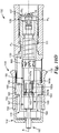
- FIGS. 1-10D illustrate a microneedle applicator 100 according to one embodiment of the present disclosure.
- the applicator 100 can include a housing 102; an actuator 104; a microneedle array holder 106 configured to hold and carry a microneedle array 107 comprising a plurality of microneedles 108; a counter assembly or mechanism 110; a first biasing element 111; a second biasing element 113; and an ejector 117 configured to eject a microneedle array 107 from the applicator 100 (e.g., by decoupling the microneedle array 107 from the holder 106).
- the microneedles 108 can be configured to treat skin (i.e., create small holes or perforations or micropores in the skin) and/or deliver an active agent via skin, particularly, mammalian skin, and particularly, transdermally.
- skin i.e., create small holes or perforations or micropores in the skin
- an active agent via skin, particularly, mammalian skin, and particularly, transdermally.
- transdermally is generally used to refer to any type of delivery of an active ingredient that crosses any portion of skin. That is, transdermally can generally include systemic delivery (i.e., where the active ingredient is transported across, or substantially through, the dermis such that the active ingredient is delivered into the bloodstream), as well as intradermal delivery (i.e., where the active ingredient is transported partially through the dermis, e.g., across the outer layer (stratum corneum) of the skin, where the active ingredient is delivered into the skin, e.g., for treating psoriasis or for local anesthetic delivery). That is, transdermal delivery as used herein includes delivery of an active ingredient that is transported across at least a portion of skin (but not necessarily all of the layers of skin), rather than merely being topically applied to an outer layer of the skin.
- systemic delivery i.e., where the active ingredient is transported across, or substantially through, the dermis such that the active ingredient is delivered into the bloodstream
- intradermal delivery i.
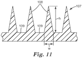
- the "microneedle array” 107 can include the microneedles 108 and any supporting structure or substrate used to support the microneedles 108 and/or to couple the microneedle array 107 to other structures or components of the applicator 100, such as the microneedle array holder 106.
- the "microneedle array” 107 can include a substrate (or carrier) 109 from which the microneedles 108 protrude, as well as additional layers or carriers.
- the microneedles 108 are formed in or directly coupled to the substrate 109, and the substrate 109 is coupled to a base or support 101.
- microneedles 108 can be formed directly into the base 101, such that the additional substrate or carrier 109 is not necessary. Also, in such embodiments, the microneedles 108 could extend across the entire area of a first side 116 of the microneedle array 107.
- the microneedle array 107 (e.g., the substrate 109 and/or the base 101) can include the first side 116 comprising the microneedles 108 and a second side 118 opposite the first side 116.
- the first side 116 can include a first major surface (e.g., defined by the substrate 109 in the illustrated embodiment) from which the microneedles 108 protrude.
- the first side 116 can be oriented toward the base 112 of the housing 102 (i.e., positioned to face the skin surface 50).
- a microneedle array 107 can be coupled to the microneedle array holder 106 such that the second side 118 faces the microneedle array holder 106, and the first side 116 is oriented toward the base 112 of the housing 102, i.e., positioned to face the skin surface 50, or be "skin-facing.”
- the housing 102, the actuator 104, the microneedle array holder 106 and/or the microneedle array 107 can be formed of a variety of materials, including but not limited to, thermoset plastics (e.g., acetal resin available under the trade designation DELRIN® DuPont Corporation, Wilmington, DE; other suitable thermoset plastics, or combinations thereof), thermoformable plastics (e.g., polyethylene, polypropylene, other suitable thermoformable plastics, or combinations thereof), or metals (e.g., stainless steel, aluminum, other suitable metals, or combinations thereof), or combinations thereof.
- thermoset plastics e.g., acetal resin available under the trade designation DELRIN® DuPont Corporation, Wilmington, DE; other suitable thermoset plastics, or combinations thereof
- thermoformable plastics e.g., polyethylene, polypropylene, other suitable thermoformable plastics, or combinations thereof
- metals e.g., stainless steel, aluminum, other suitable metals, or combinations thereof
- the housing 102 can include a base 112, which can be generally planar and configured to be positioned toward a skin surface 50 (see, e.g., FIGS. 7A-7C ).
- the base 112 can be configured to touch the skin surface 50 during application; however, the base 112 is generally not configured to remain coupled to the skin 50, and does not include an adhesive. That is, generally, the base 112 is a non-adhesive surface.
- the housing 102 can further include or define a cavity (or chamber, or pocket, or recess, etc.) 114. As shown, the base 112 can define an opening 115 that opens into the cavity 114.
- the housing 102, and particularly, the cavity 114 can be configured to house at least a portion of the microneedle array holder 106 and the microneedle array 107 (e.g., when coupled to the holder 106), i.e., prior to application of the microneedles 108 to the skin 50.
- an elastomeric annular cap can be coupled to the base 112 surrounding the opening 115, which can enhance the connection and/or friction between the housing 102 and the skin 50 when the applicator 100 is positioned on the skin 50 for use.
- the microneedle array holder 106 can be located within the housing 102 and can be configured to hold a microneedle array 107 and to stamp the microneedles 108 into a substrate of interest (e.g., skin). As shown in FIG. 3 , the microneedle array holder 106 can include a first (or bottom) side 121 that can be configured to be positioned toward a skin surface, i.e., skin-facing, and which can be configured to receive the microneedle array 107. By way of example only, the microneedle array holder 106 is shown as having two apertures 123 that open at the first side 121 and which are each dimensioned to receive an upwardly-extending projection 125 from a microneedle array 107.
- the projections 125 and the apertures 123 can be sized and configured to allow each projection 125 to pass through an aperture 123 and snap onto a backside of the holder 106 via a snap-fit-type engagement.
- the holder 106 can include one or more projections or flanges 167 that can be configured to be coupled to an outer surface or edge of the microneedle array 107.
- the projections 167 of the illustrated embodiment are configured to be coupled to an outer edge of the base 101 of the microneedle array 107 in a snap-fit-type engagement.
- the snap-fit engagement between the microneedle array 107 and the holder 106 of the illustrated embodiment can allow for facile engagement between a microneedle array 107 and the holder 106; however, the above-described types of coupling or engagement are shown by way of example only, and it should be understood that a microneedle array 107 can be coupled (i.e., removably coupled) to the holder 106 by a variety of coupling means, including, but not limited to, press-fit or friction-fit engagement, other types of snap-fit engagement, magnets, hook-and-loop fasteners, adhesives, cohesives, clamps, heat sealing, stitches, staples, screws, nails, rivets, brads, crimps, detents, other suitable coupling means, or combinations thereof.
- coupling means including, but not limited to, press-fit or friction-fit engagement, other types of snap-fit engagement, magnets, hook-and-loop fasteners, adhesives, cohesives, clamps, heat sealing, stitches, staples
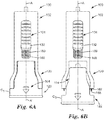
- the ejector (or “ejector assembly”) 117 can include an elongated pin or shaft 135 that can extend generally along (or generally parallel to) a longitudinal axis A and can include a portion that is accessible from the exterior of the housing 102 (see FIGS. 1 and 4A-4B ).
- the ejector pin 135 can include a first end 136 that extends beyond a top of the housing 102 (e.g., via an opening 166 formed in a top wall or portion of the housing 102), and a second end 138 that can be dimensioned to pass through a bore 124 in the microneedle array holder 106.
- the ejector pin 135 can be movable between a first position in which the ejector pin 135 (e.g., the second end 138 thereof) does not extend past the first side 121 of the holder 106 and/or does not interfere with the microneedle array 107, to a second position in which the ejector pin 135 (e.g., the second end 138 thereof) does extend past the first side 12 and/or does interfere with the microneedle array 107.
- the ejector pin 135 can be moved relative to the housing 102, the holder 106, the microneedle array 107 and optionally other components of the applicator 100 with sufficient force to decouple the microneedle array 107 from the microneedle array holder 106, causing the microneedle array 107 to be ejected from the applicator 100, allowing the microneedle array 107 to be discarded and/or replaced by another microneedle array 107.
- the ejector 117 can include a biasing element (or a resilient element) 137 configured to bias the ejector pin 135 in its first position, while allowing the ejector pin 135 to be moved against the bias of the biasing element 137 to move the ejector pin 135 to its second position.
- the ejector biasing element 137 is in the form of a flat spring; however, any suitable biasing element, such as those described below, can be employed.
- the ejector 117 or a portion thereof (e.g., one or more projections or flanges 139) can be configured to be coupled to the housing 102 so as to fix the ejector 117 with respect to the housing 102 and the longitudinal axis A.
- two (e.g., diametrically-opposed) projections 139 on the ejector 117 are each received within a channel 141 formed in an inner surface 140 of the housing 102 (see FIGS. 4A and 4B ).
- the ejector pin 135 can serve to align at least some of the other components or elements of the applicator 100, e.g., to align such elements centrally with respect to the housing 102. Such alignment can also facilitate coupling various elements together and can facilitate their collective and/or interactive movement.
- Such elements can include the counter assembly 110, at least a portion of the actuator 104, and the microneedle array holder 106.
- the ejector pin 135 can be centered with respect to the housing 102 and can be aligned along the longitudinal axis A of the applicator 100.
- the actuator 104 can include a plunger (or shaft, or piston) 130, as well as any other components that are configured to facilitate movement of the plunger 130.
- the actuator 104 can include one or more buttons 132 or other manually engageable portions or elements that are coupled to the plunger 130 but at least partially reside on the exterior of the housing 102 to allow a user to manually manipulate and control the plunger 130 when the applicator 100 is assembled.
- the buttons 132 are illustrated by way of example as being slide buttons. Two simultaneously-operable slide buttons are shown by way of example only and for facile user manipulation.
- the plunger 130 can include a first end 131 that can be coupled to, or can interact with, the buttons 132 (e.g., via the counter assembly 110 or other intervening elements, if employed), and a second end 133 that is coupled to, or can interact with, the microneedle array holder 106.
- the second end 133 of the plunger 130 is illustrated as being dimensioned to be received within a recess 134 formed in an upper portion of the holder 106.
- the second end 133 is configured to be coupled inside the recess 134 via a snap-fit-type engagement. This type of engagement is illustrated by way of example only, but it should be understood that any of the coupling means described above (with respect to the coupling between the microneedle array holder 106 and the microneedle array 107) can be employed.
- the actuator 104 can further include at least a portion of the counter assembly 110, if employed, of which a portion can interact with or be coupled to the button(s) 132, and another portion can interact with and/or be coupled to the plunger 130 (e.g., the first end 131 thereof).
- the buttons 132 when a user slides the buttons 132 downwardly (e.g., toward a skin surface 50) relative to the housing 102 from an initial position to an actuated position, the buttons 132 can cause at least a portion of the counter assembly 110 to also move downwardly relative to the housing 102, which in turn, can cause the plunger 130 to move from a first position P 1 (see FIG. 4A ) to a second position P 2 (see FIG. 4B ).
- buttons 132, the plunger 130, and any other intervening structures or elements can collectively be referred to as the "actuator" 104.
- the plunger 130 can itself be referred to as the "actuator” and the buttons 132, the actuator 130, and any other intervening structures or elements (such as portions of the counter assembly 110, if employed) can collectively be referred to as an "actuator assembly.”
- the actuator 104 can move as an ensemble in response to user manipulation.
- the above-described elements making up the actuator 104 are coupled together and movable together from the first position P 1 to the second position P 2 .
- the collection of components described above will be referred to in the following description as simply the "actuator" 104, and such description will be understood to apply to any of the above-described components of the actuator 104, as well as the collection of such components.
- the elements of the actuator 104 are generally fixed with respect to one another for effective energy transfer and movement, it should be understood that, in some embodiments, there may be some give or play between elements of the actuator 104.
- the first biasing element 111 can be configured to bias the actuator 104 in the first position P 1, such that a user can move the actuator 104 to the second position P 2 against the bias of the first biasing element 111, and the first biasing element 111 can return, or assist in returning, the actuator 104 to the first position P 1.
- the actuator 104 can be movable with respect to the housing 102 (e.g., against the bias of the first biasing element 111) between the first position P 1 and the second position P 2 to cause the microneedle array holder 106 to move, respectively, between
- the first, retracted position H 1 and the second, extended position H 2 can be spaced a distance from one another along an actuation axis A', such that the microneedle array holder 106 is movable along the actuation axis A', e.g., relative to the housing 102, between the first, retracted position H 1 and the second, extended position H 2 .
- the actuation axis A' can be aligned along the longitudinal axis A of the applicator 100 (or of the housing 102), such that the holder 106 is movable along the direction in which the applicator 100 (or the housing 102) is elongated.
- Such embodiments can provide an intuitive and user-friendly design.
- the actuation axis A' may not be exactly aligned along the longitudinal axis A, but the actuation axis A' can be substantially parallel to the longitudinal axis A. However, the actuation axis A' need not be aligned along or substantially parallel to the longitudinal axis A.
- the actuation axis A' can generally be oriented substantially normal with respect to the skin surface 50 (and the first side 121 of the holder 106, as well as the first side 116 of the microneedle array 107 when coupled to the holder 106), but this need not be the case. Rather, in some embodiments, the actuation axis A' can be arcuate or define otherwise nonlinear path(s), etc.
- the actuation axis A' simply refers to movement between the first, retracted position H 1 and the second, extended position H 2 .
- the holder 106 When the microneedle array holder 106 is in the first, retracted position H 1 , the holder 106 can be recessed within the housing 102, such that the holder 106 (and the microneedle array 107, when coupled to the holder 106) does not extend beyond the base 112 of the housing 102. That is, when the microneedle array holder 106 is in the first, retracted position H 1 and a microneedle array 107 is coupled to the holder 106, the microneedle array 107 can also be in a first, retracted position M 1 (see, e.g., FIGS.
- microneedle array 107 is recessed within the housing 102 such that the microneedle array 107 does not contact (or is not positioned to contact) the skin surface 50 when the base 112 of the housing 102 is positioned on the skin surface 50.
- the microneedle array 107 can be housed within the cavity 114 and can be recessed with respect to the base 112 in its retracted position M 1 .
- the microneedle array 107 can also be in a second, extended position M 2 (see, e.g., FIG. 7B ), e.g., in which at least a portion of the microneedle array 107 is positioned to contact the skin surface 50 when the base 112 of the housing 102 is positioned on the skin surface 50.
- microneedle array holder 106 and the microneedle array 107 are in their respective second positions H 2 and M 2 , at least a portion of the microneedle array 107 (and, potentially, a portion of the microneedle array holder 106) can extend beyond the base 112 of the housing 102. However, this need not be the case, and in some embodiments, it can be preferred for this not to be the case.
- the microneedles 108 can be positioned close enough to the base 112 of the housing 102 (while still being recessed within the housing 102 and without extending beyond the base 112), such that when the base 112 is pressed onto the skin surface 50, the skin 50 is caused to deform or dome up through the opening 115 and into the cavity 114 to a position where the skin 50 is contacted by the microneedles 108.
- This configuration can be preferred, e.g., in the case of an unskilled user, where it is desirable for the microneedles 108 never to extend beyond the base 112 of the housing 102 in such a way that the unskilled user could potentially use the applicator 100 to scrape the microneedles 108 along the skin surface 50.
- the second, extended position H 2 can also be used to load a microneedle array 107 onto the holder 106, e.g., by picking up a microneedle array 107 from a loading tray 129, as shown in FIG. 5 . In some embodiments, this can be facilitated by allowing the microneedle array holder 106, or a portion thereof (e.g., the first side 121 thereof) to extend beyond the base 112 of the housing 102. In such embodiments, the second, extended position H 2 can be located relative to the base 112 of the housing 102 at a position that allows for loading a microneedle array 107, as well as for perforating the skin surface 50 with the microneedles 108.
- At least a portion of the housing 102 can be movable relative to the remainder of the housing 102 and/or removable from the remainder of the housing 102 in order to expose the microneedle array holder 106.
- Such a movable and/or removable portion of the housing 102 can allow the microneedle array holder 106 to easily extend beyond a portion of the housing 102, e.g., to load a microneedle array 107.
- the portion of the housing 102 that can be movable and/or removable can then be replaced, or returned to its original position, after the microneedle array 107 has been loaded.
- the housing 102 can be formed of more than one portion, and at least one of the plurality of portions can be movable with respect to, and/or removable from, other portion(s) in order to open or access an interior of the microneedle applicator 100.
- that same (re)movable portion can define the base 112, the opening 115 and a portion of the cavity 114. As shown in the embodiment of FIGS.
- the housing 102 can include (i) a first portion 120 configured to house most of the components of the applicator 100, such as the actuator 104, the microneedle array holder 106, the counter assembly 110 (if employed), and the first biasing element 111; and (ii) a second portion 122 that defines the base 112 and the opening 115 formed therein that is movable and/or removable to a position (i.e., an "off-axis position") where the actuation axis A' no longer passes through the opening 115, and the microneedle array holder 106 is exposed.
- an "off-axis" position can facilitate loading a microneedle array 107 onto the holder 106.
- the second portion 122 can be referred to as a "cover,” and the first portion 120 of the housing 102 can be referred to as the “housing” 102.
- this nomenclature will be used below to describe the illustrated embodiment.
- the cover 122 can define the base 112 and the opening 115, can be configured to be positioned on the skin surface 50, and can be configured to be easily grasped and manipulated (e.g., by hand).
- the cover 122 can be movable, relative to the housing 102 (and the microneedle array holder 106, as well as the other components, including the actuator 104 and the counter assembly 110) between
- off-axis generally refers to a position in which the axis of interest (e.g., the longitudinal axis A and/or the actuation axis A') does not pass through opening 115, such that when the microneedle array holder 106 is moved between the retracted position H 1 and the extended position H 2 , there is no interaction with the cover 122. Said another way, the microneedle array holder 106 (and the microneedle array 107 when coupled to the holder 106) does not enter into, or is not located in, the portion of the cavity 114 defined by the cover 122 when the cover 122 is in the "off-axis" second position C 2 .
- the axis of interest e.g., the longitudinal axis A and/or the actuation axis A'
- the cover 122 can be further movable between the first position C 1 , the second position C 2 , and a third position C 3 (see FIG. 6B ) spaced a distance along the longitudinal axis A and/or the actuation axis A' from the first position C 1 .
- the cover 122 before the cover 122 is moved (e.g., swung, slid, etc.) from the first position C 1 to the "off-axis" second position C 2 (or vice versa) the cover 122 can first be moved (e.g., slid) to the intermediate third position C 3 , e.g., to provide clearance for the cover 122 to be moved to the "off-axis" second position C 2 .
- the microneedle applicator 100 when the cover 122 is in the first position C 1 , the microneedle applicator 100 can be considered to be in an "assembled” configuration, and when the cover 122 is in the third position C 3 , the microneedle applicator 100 can be considered to be in a "disassembled” configuration, even though both the first position C 1 and third position C 3 could be considered to be "on-axis.”
- the third position C 3 is generally not an "off-axis" position, and the actuation axis A' (and the longitudinal axis A) can still pass through the opening 115 when the cover 122 is in the third position C 3 ; however, this need not be the case.
- the third position C 3 can be employed to facilitate movement of the cover 122 between the first position C 1 and the second position C 2 , and is located intermediately of the first position C 1 and the second position C 2 , such that the cover 122 moves through the third position C 3 when moved between the first position C 1 and the second position C 2 .
- the cover 122 can include one or more indicators 164 that can include directional cues or instructions to clearly indicate to a user (i.e., an unskilled user) how to move the cover 122.
- the cover 122 includes a directional arrow pointing downwardly to indicate to a user that the cover 122 can be slid downwardly e.g., to the third position C 3 .
- the cover 122 Once the cover 122 is in the third position C 3 , another indicator or directional cue can be exposed to indicate how to move the cover 122 to the second position C 2 , or the cover 122 can be configured to be obviously movable (e.g., slidable and/or pivotable) at this point, so that a user will readily discern how the cover 122 can be moved to an "off-axis" position to expose the microneedle array holder 106.
- the cover 122 can be configured to be obviously movable (e.g., slidable and/or pivotable) at this point, so that a user will readily discern how the cover 122 can be moved to an "off-axis" position to expose the microneedle array holder 106.
- the cover 122 can be removable from the housing 102; however, in some embodiments, the cover 122 can remain coupled to the housing 102 when the cover 122 is in the first position C 1 , the second position C 2 , and the third position C 3 . In embodiments in which the cover 122 is removable from the housing 102, the cover 122 can be in the "off-axis" second position C 2 when the cover 122 is removed or decoupled from the housing 102.
- the cover 122 and the housing 102 can each be formed of more than one part or portion.
- the housing 102 can be formed of a top portion 126 and a bottom portion 128.
- the inner surface 140 of the housing 102, and particularly, the inner surface 140 of the top portion 126 can be configured to receive (e.g., can include various recesses for receiving) a majority of the components of the applicator 100.
- the top portion 126 and the bottom portion 128 of the housing 102 can be coupled together by any of the coupling means described above, as well as by a variety of other permanent or removable coupling means, including, but not limited to, heat sealing, stitches, staples, screws, nails, rivets, brads, crimps, welding (e.g., sonic (e.g., ultrasonic) and/or thermal welding), any thermal bonding technique (e.g., heat and/or pressure applied to one or both of the components to be coupled), other suitable coupling means, or combinations thereof.
- the top portion 126 and the bottom portion 128 are configured to snap together, and further include two threaded apertures 119 for receiving two screws 127.
- At least one of the top portion 126 and the bottom portion 128 of the housing 102 can include one or more engagement features configured to engage features of the cover 122, and optionally, further configured to allow relative movement between the cover 122 and the housing 102 to allow the cover 122 to be moved between the first position C 1 , the second position C 2 , and in some embodiments, the third position C 3 .
- the cover 122 includes two arms 146, and each arm 146 includes engagement features configured to engage with engagement features formed in the outer surface 145 of the top portion 126 and the bottom portion 128 of the housing 102.
- each arm 146 of the cover 122 includes one or more first projections 142 dimensioned to be received in one or more recesses 144 formed in the outer surface 145 of the housing 102. Since each arm 146 of the cover 122 and each of the top portion 126 and the bottom portion 128 of the housing 102 include the same engagement features, one side will be described for simplicity, but it should be understood that the same description can apply to the other side as well.
- a first recess 144a formed in the outer surface 145 of the housing 102 can be elongated and dimensioned to match the shape of the first projection 142 on the cover 122, which is also elongated in shape, such that when the first projection 142 is received in the first recess 144a, the first projection 142 is seated in the first recess 144a, and the cover 122 is not able to be moved (e.g., rotated) to the "off-axis" second position C 2 .
- the second recess 144b can be round and/or dimensioned to allow the first projection 142 to be rotated therein about a rotational axis R (see FIG.
- the rotational axis R can be considered to be oriented substantially perpendicularly with respect to a direction or line that is normal to the skin surface 50, or substantially parallel with respect to the skin surface 50 (or a tangent thereof).
- the first recess 144a and the second recess 144b can be connected via a first slot 143 that can be dimensioned to receive the first projection 142 and allow the first projection 142 to be moved (e.g., slid longitudinally) between the first recess 144a and the second recess 144b.
- the recesses 144 can also be described as forming portions of the first slot 143, i.e., defining detent positions, or stops, along the first slot 143.
- the first recess 144a corresponds to the first position C 1 of the cover 122
- the second recess 144b corresponds to the third position C 3 of the cover 122.
- the second recess 144b can allow for rotation of the first projection 142 therein, which can also allow for rotation of the cover 122 relative to the housing 102, such that when the first projection 142 is located in the second recess 144b, the cover 122 can swivel or pivot relative to the housing 102, i.e., to be moved to the second position C 2 .
- the cover 122 can be moved to one of two second positions C 2 , i.e., the cover 122 can be moved to either side relative to the housing 102 in order to move to the second position C 2 .
- only one second position C 2 is available to the cover 122, or the cover 122 is moved to the second position C 2 by being at least partially decoupled from the housing 102.
- the engagement features on the housing 102 can further include an arcuate slot 148 that can be connected to the first slot 143 and/or the second recess 144b by a second slot 150.
- the arcuate slot 148 is positioned symmetrically about the first slot 143 and the recesses 144, which allows the cover 122 to be moved to either side of the housing 102 to move to a second position C 2 .
- the arcuate slot 148 and the second slot 150 can be dimensioned to receive a second projection 152 on the cover 122 that is spaced a distance (e.g., a longitudinal distance) from the first projection 142.
- the first projection 142 is larger than the second projection 152, and the second projection round in cross-section and is domed.
- the first projection 142 and the second projection 152 can be located relative to one another such that when the first projection 142 is positioned in the first recess 144a, the second projection 152 is located in the second recess 144b.
- the first projection 142 is moved into the second recess 144b, and the second projection 152 is moved through the second slot 150, into the arcuate slot 148.
- the first projection 142 can then be rotated in the second recess 144b, and the second projection 152 can be moved in (e.g., slid along) the arcuate slot 148 to either side, thus, causing the cover 122 to move to one of two second positions C 2 .
- the engagement features in the outer surface 145 of the housing 102 can further include one or more third recesses 154, which can each be spaced a distance from an end of the arcuate slot 148 and can define detent positions, or stops, for the second projection 152.
- Three third recesses 154 are shown by way of example only, each third recess 154 being spaced a short distance from an end of the arcuate slot 148.
- the third recess(es) 154 can allow the cover 122 to be stopped or held in either of the two second positions C 2 . That is, the second projection 152, along with the third recess(es) 154, can be used to create or define detents or stops that correspond to discrete second positions C 2 for the cover 122.
- the above-described specific arrangement of engagement features between the housing 102 and the cover 122 is only one possible embodiment of engagement between the cover 122 and the housing 102 that allows for movement (and even discrete positions) between the cover 122 and the housing 102.
- the illustrated embodiment allows for decoupling of the cover 122 and the housing 102, because the engagement features on the cover 122 (e.g. the first projection 142 and/or the second projection 152) can be configured to engage the engagement features on the housing 102 (e.g., the first and second recesses 144a, 144b and the third recess 154) in a snap-fit-type engagement, e.g., by providing some flex in arms 146 of the cover 122.
- Other removable coupling means such as those described above can also be employed to allow the cover 122 and the housing 102 to be decoupled from one another (and recoupled back together when desired).
- FIGS. 1 and 6A illustrate the applicator 100 in an assembled configuration, with the cover 122 in the first position C 1 .
- the applicator 100 is empty, i.e., the applicator 100 does not yet include a microneedle array 107.
- the applicator 100 can be changed to a diassembled configuration and the cover 122 can be moved to the third position C 3 , spaced a longitudinal (e.g., "on-axis") distance from the first position C 1 .
- movement to the third position C 3 can occur as a result of the first projection 142 on each cover arm 146 moving from its corresponding first recess 144a to its second recess 144b on the housing 102, as well as the second projection 152 on the cover arm 146 moving from the corresponding second recess 144b through the second slot 150 to the arcuate slot 148.
- the cover 122 In the third position C 3 , i.e., when the first projection 142 is positioned in the second recess 144b, the cover 122 can be free to rotate or pivot about the rotational axis R, e.g., to one of a plurality of second positions C 2 .
- the cover 122 can be slidable along the longitudinal axis A of the housing 102 (or the applicator 100) to move between the first position C 1 and the third position C 3 , and the cover 122 can be rotatable about the rotational axis R (see FIG. 2 ) that is oriented substantially perpendicularly with respect to the longitudinal axis A to move between the third position C 3 and the second position C 2 .
- a base 162 of the housing 102 (or a base 162 of the first portion 120 of the housing 102) is at least partially exposed.
- the base 162 of the housing 102 defines an opening 165 formed therein and provides access into the cavity 114 within the housing 102.
- the microneedle array holder 106, and particularly, the first side 121 thereof, is also at least partially exposed when the cover 122 is moved to the third position C 3 .
- the base 162 can also be configured to be positioned toward the skin surface 50 (i.e., skin-facing), but this need not be the case and depends on the overall configuration of the applicator 100.
- the cover 122 can then be moved (e.g., from the third position C 3 ) to one side of the housing 102 to one of two second positions C 2 .
- movement to a second position C 2 can occur as a result of the first projection 142 being rotated about rotational axis R in the second recess 144b, and as a result of moving the second projection 152 along at least a portion of the arcuate slot 148, and optionally, with enough force to move into one of the third recesses 154.
- the base 162 of the housing 102 is exposed when the cover 122 is in the second position C 2 , whereas, as shown in FIG.
- the base 162 of the housing 102 is covered by the cover 122 when the cover 122 is in the first position C 1 .
- the cover 122 or at least a portion thereof, can also be coupled to the base 162 of the housing 102 when the cover 122 is in the first position C 1 .
- the base 162 can be at least partially exposed when the cover 122 is in the third position C 3 .
- the microneedle array holder 106, and particularly, the first side 121 thereof, is exposed when the cover 122 is moved to the second position C 2 .
- the microneedle array holder 106 is empty and does not include a microneedle array 107, and the loading tray 129 comprising a microneedle array 107 is temporarily coupled to the housing 102.
- the housing 102 includes a pair of projections 155 (see also FIGS. 4A and 4B ) that extend downwardly from the base 162, and which are configured to be received within a well (or recess, or pouch) 156 of the tray 129 that comprises the microneedle array 107.
- the projections 155 fit within the well 156 by a friction-fit or press-fit-type engagement to hold the tray 129 adjacent the base 162 of the housing 102 during the loading process.
- a top surface 157 of the tray 129 can be positioned adjacent the base 162 of the housing 102, and can optionally include an adhesive.
- kits comprising an applicator of the present disclosure and the loading tray 129 comprising one or more microneedle arrays 107.
- the tray 129 can include a plurality of wells 156, and each well 156 can include a microneedle array 107.
- the tray 129 can include one continuous tray 129 with a plurality of wells 156, or the tray 129 can include a plurality of segments 158, as shown, that each include one or more wells 156 (and one or more microneedle arrays 107).
- Each segment 158 can be separated from an adjacent segment 158 by a score line or perforation 159.
- the microneedle array holder 106 is exposed when the cover 122 is in the second position C 2 .
- the holder 106 can be moved from its retracted position H 1 (see FIG. 6C ) to its extended position H 2 , e.g., to pick up the microneedle array 107 from the tray 129.
- the microneedle array holder 106 can be movable through the opening 165 in the base 162 of the housing 102 between its retracted position H 1 and its extended position H 2 .
- this movement of the holder 106 can be accomplished by a user manipulating the one or more buttons 132, e.g., by sliding the button(s) 132 downwardly relative to the housing 102, which in turn, causes the actuator 104 to move from its first position P 1 to its second position P 2 (see FIGS. 4A and 4B ).
- the microneedle array holder 106 can pick up (or load) the microneedle array 107 by pressing the first side 121 of the holder 106 toward the second side 118 of the microneedle array 107 to allow the upwardly-extending projections 125 on the microneedle array 107 to pass through the apertures 123 on the holder 106 and snap onto a backside of the holder 106 (or at least onto a backside of a face of the holder 106).
- the holder 106 can be returned to its retracted position H 1 (and the microneedle array 107) can be positioned in its retracted position M 1 , as shown in FIG. 6E .
- the first biasing element 111 can bias the actuator 104 in its first position P 1, and therefore, the holder 106 can be biased in its retracted position H 1 , such that the button(s) 132 merely need to be released after the microneedle array 107 has been coupled to the holder 106 to allow the holder 106 to return to its retracted position H 1 .
- a user can also guide the button(s) 132 back to the initial position.
- the cover 122 can be moved from its second position C 2 back to the third position C 3 , as shown in FIG. 6B , and finally, back to the first position C 1 , as shown in FIG. 6A .
- the first projection 142 on the cover 122 in moving from the second position C 2 to the third position C 3 , can be rotated about rotational axis R in the second recess 144b, and enough force can be applied to overcome the detent between the third recess 154 on the housing 102 and the second projection 152 on the cover 122 to move the second projection 152 into and along the arcuate slot 148 until the second projection 152 is back in line with the second slot 150 (i.e., the third position C 3 ).
- the first projection 142 can be slid in the first slot 143 from the second recess 144b to the first recess 144a, and the second projection 152 can be slid from the arcuate slot 148, through the second slot 150, and into the second recess 144b.
- the interaction between the first projection 142 and the first recess 144a can also function as a detent or stop to maintain the cover 122 in the first position C 1 until sufficient force is applied to move the first projection 142 out of the first recess 144a.
- the above process describes loading a microneedle array 107 into the illustrated embodiment of the applicator 100; however, it should be understood that a very similar process can be employed, with appropriate modifications, to load a microneedle array 107 into any applicator of the present disclosure.
- the cover 122 can simply be removed from the housing 102 to expose the microneedle array holder 106 and the base 162 of the housing 102, and the cover 122 can be replaced on the housing 102 after the microneedle array 107 has been loaded.
- the extended position H 2 of the holder 106 can be used not only for delivering the microneedles 108 to the skin surface 50, but also for loading a microneedle array 107 onto the holder 106.
- the extended position H 2 of the holder 106 can also be referred to as a "loading" position and/or a "treatment" position.
- the holder 106 when the cover 122 is removed from the housing 102 or in the second position C 2 , the holder 106 can extend beyond the base 162 of the housing 102 when the holder 106 is in its extended position H 2 , e.g., to facilitate accessing and picking up a microneedle array 107, and the holder 106 can be at least partially located in the cavity 114 of the housing 102 when in its retracted position H 1 .
- the holder 106 does not extend beyond the base 162 of the housing 102 when in its retracted position H 1 .
- the first side 121 of the holder 106 can be recessed with respect to the base 162 of the housing 102 when the holder 106 is in the retracted position H 1 , or the first side 121 can be coplanar or flush with the base 162 of the housing 102.
- the housing 102 can be configured to contain or "house" the microneedle array holder 106 at least when the holder 106 is in the retracted position H 1 .
- safety can be enhanced by having the holder 106 be sufficiently recessed with respect to the base 162 of the housing 102 when in the retracted position H 1 , such that after a microneedle array 107 has been picked up, the microneedle array 107 is also recessed with respect to the base 162.
- Such a configuration can minimize the likelihood that a user would prematurely or undesirably come into contact with the microneedles 108.
- the cover 122 can be removable from the housing 102, and as such, when the cover 122 is described as being “movable relative to” or “movable with respect to” the housing 102 (or the microneedle array holder 106), it should be understood that this can include being removable from the housing 102 in such a way that the cover 122 can be moved from the "on-axis" first position C 1 to an "off-axis" second position C 2 .
- the cover 122 can also be removable from the housing 102 when the cover 122 is in any of its positions, including the first position C 1 , the second position C 2 , and the third position C 3 .
- One advantage of employing a cover 122 that is movable with respect to, or removable from, the housing 102 is that the holder 106 can be exposed to pick up a microneedle array 107 without requiring a user to ever come into contact with the microneedle side of the microneedle array 107.
- the configuration of the tray 129 and the placement of the microneedle array 107 in a well 156 of the tray 129 i.e., with the first side 116 of the array 107 facing into the well 156) can also inhibit a user from prematurely or unintentionally coming into contact with the microneedles 108.
- the cover 122 can be moved to the first position C 1 wherein the microneedle array 107 is located within (e.g., entirely within) the cavity 114 (e.g., that is at least partially defined by the cover 122) and is recessed with respect to the base 112, such that the microneedles 108 are not exposed for undesirable or premature puncturing of skin.
- the (re)movable cover 122 can provide a safety feature to the applicator 100.
- the cover 122 can be rotatably or pivotally movable with respect to the housing 102, e.g., about the rotational axis R.
- the cover 122 can be slidably movable with respect to the housing 102, e.g., as shown in the illustrated embodiment when the cover 122 is moved between the first position C 1 and the third position C 3 .
- the applicator 100 employs rotational (or pivotal) movement and sliding movement between the cover 122 and the housing 102 when the cover 122 is moved between the first position C 1 and the second position C 2 .
- the cover 122 can be slidable with respect to the housing 102 even in moving between the second position C 2 and the third position C 3 (or between the second position C 2 and the first position C 1 ), and that the slide-and-swivel cover 122 of the illustrated embodiment is shown by way of example only.
- a combination of sliding, pivoting and/or other actions can be used to move the cover 122 with respect to the housing 102 between the various positions.
- the cover 122 is movable between three positions - the first position C 1 , the second position C 2 and the third position C 3 ; however, it should be understood that, in general, the cover 122 is movable between the first position C 1 and an "off-axis" second position C 2 , and the intermediate third position C 3 is shown by way of example only. In some embodiments, a plurality of intermediate "third" positions C 3 can be employed.
- the ejector pin 135 can be moved from its first position to its second position, against the bias of the biasing element 137, until the second end 138 of the ejector pin 135 presses against the second side 118 of the microneedle array 107 with sufficient force to decouple the microneedle array 107 and the holder 106 (e.g., to disengage the projections 125 on the microneedle array 107 from the apertures 123 on the holder 106 and to disengage the projections 167 from the base 101 of the microneedle array 107).
- the cover 122 can be moved to the second position C 2 to facilitate microneedle array loading as well as ejection.
- the applicator 100 can include a counter assembly 110 that can be configured to count the number of times the microneedle array 107 is applied to skin, and particularly, is configured to count the number of times the microneedle array holder 106 is moved between the retracted position H 1 and the extended position H 2 .
- the counter assembly 110 can include a display 168 (see, e.g., FIGS. 1 , 3 , 4A-4B , and 6A-6E ) that is indicative of this count.
- the display 168 displays an arabic numeral representative of the count.
- the housing 102 can include an opening or a window 169 (see, e.g., FIGS.
- FIGS. 4A and 4B The top portion 126 of the housing 102 is shown in FIGS. 4A and 4B , with a front of the top portion 126 hidden from view. As a result, the opening 169 is not visible in FIGS. 4A and 4B .
- the counter assembly 110 can form a portion of, or can be coupled to the actuator 104, such that the counter assembly 110 is also movable (e.g., against the bias of the first biasing element 111) between the first position P 1 and the second position P 2 .
- the counter assembly 110 can be configured to count the movement from the first position P 1 to the second position P 2 as a count, as well as the movement from the second position P 2 to the first position P 1 as an additional count.
- the counter assembly 110 is configured to count one revolution or one round as a count - i.e., a "count” in the illustrated embodiment represents when the actuator 104 has moved from the first position P 1 to the second position P 2 and back to the first position P 1 .
- the "count” can also be considered to represent the number of times a microneedle array 107 has contacted the skin surface 50, and/or the number of times the microneedle array holder 106 has been moved between the retracted position H 1 and the extended position H 2 .
- the counter assembly 110 can be employed in embodiments in which it is acceptable for a microneedle array 107 to be applied to the skin surface 50 more than once before being discarded, up to a maximum number of applications.
- the applicator 100 can include a locking feature, such that the applicator 100 is inhibited from being used after the maximum number of applications has been reached, e.g., until the microneedle array 107 is discarded (e.g., via the ejector 117) and replaced by a new microneedle array 107.
- the counter assembly 110 can be configured to stop at the maximum number of applications until it is triggered to begin recounting by replacing the microneedle array 107.
- the counter assembly 110 is mechanically coupled to the actuator 104 and the first biasing element 111, such that movement of the actuator 104 (e.g., by manipulating the button(s) 132) and the bias of the first biasing element 111 drive the counter assembly 110.
- One exemplary counting process is illustrated in FIGS. 6A-6E .
- the counter display 168 originally displays a "0" when the applicator 100 is empty, representing that the microneedle array 107 has not been used.
- FIGS. 1 the counter display 168 originally displays a "0" when the applicator 100 is empty, representing that the microneedle array 107 has not been used.
- the button(s) 132 can be moved downwardly from an original to an actuated position to move the microneedle array holder 106 to the extended position H 2 to load a microneedle array 107.
- the display 168 is temporarily not visible, i.e., the opening 169 in the housing 102 is covered by at least one of the buttons 132 when the actuator 104 is in the second position P 2 .
- the button(s) 132 are allowed to return (e.g., due to the bias of the first biasing element 111)
- the counter assembly 110 is triggered to increment a count, and as shown in FIG. 6E , the display 168 has incremented a count at this point, and now displays numeral "1.”
- the first counter display position can display a blank or some other symbol representing that the microneedle array holder 106 is empty, and can increment to a "0" after loading. Then, if the microneedle array holder 106 is moved to its extended position H 2 with the microneedle array 107 coupled to the holder 106, that movement will be counted, and the counter display 168 will increment to a "1.”
- FIGS. 9-10D One example of a counter assembly that can be employed in applicators of the present disclosure is illustrated in FIGS. 9-10D and described in greater detail below.
- the applicator 100 can be configured for safe use, especially by an unskilled user.
- the movable cover 122 can be employed to enhance the safety of the applicator 100.
- the safety of the applicator 100 can be enhanced by limiting the amount of force a user can apply to the skin 50 with the microneedles 108. That is, some embodiments of the applicator 100 can include force dampening configured to limit the threshold application force that can be applied to skin 50 with the applicator 100, and particularly, with the microneedles 108.
- the applicator 100 can include a force-dampening mechanism, such that when a user continues to press the applicator 100 (and the microneedles 108) into the skin 50, the applicator 100 is configured to inhibit any force beyond a certain threshold from actually being transferred to the skin 50.
- a force-dampening mechanism that can be employed is illustrated in FIGS. 7A-7C and 8 .
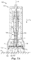
- FIGS. 7A-7C illustrate the applicator 100 in cross-section as the applicator 100 is applied to the skin surface 50.
- FIG. 7A shows the base 112 of the cover 122 (or of the housing 102, in embodiments in which a movable cover 122 is not employed) being applied to the skin surface 50.
- the actuator 104 is in the first position P 1 with respect to the housing 102 (e.g., with respect to the longitudinal axis A of the housing 102).
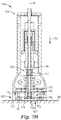
- FIG. 7B shows the actuator 104 being moved against the bias of the first biasing element 111 from the first position P 1 to the second position P 2 to move the holder 106, respectively, from its retracted position H 1 to its extended position H 2 , and to also move the microneedle array 107, respectively, from its retracted position M 1 to its extended position M 2 , wherein the microneedles 108 are positioned in contact with the skin surface 50 to puncture or perforate the skin surface 50.
- FIG. 7C shows the skin 50 doming or deforming up into the cavity 114 for illustration purposes.
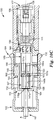
- the microneedle array 107 will be moved away from the skin surface 50 accordingly, via the microneedle array holder 106, by moving the holder 106 against the bias of the second biasing element 113 from the extended position H 2 to a third, dampened position H 3 . Accordingly, the microneedle array 107 can be moved to a dampened position M 3 .
- the description herein pertaining to the dampened position H 3 of the microneedle array holder 106 can also apply to the dampened position M 3 of the microneedle array 107.
- the dampened position H 3 , M 3 is located intermediately between the retracted position H 1 , M 1 and the extended position H 2 , M 2 .
- the second biasing element 113 can be referred to as a "dampening element” or a "force dampening element.”
- the dampened position H 3 , M 3 is illustrated as one discrete position for simplicity, it should be understood that the "dampened position" H 3 , M 3 can refer to any position to which the microneedle array holder 106 (and/or the microneedle array 107) is moved when a threshold application force is achieved that is sufficient to overcome the bias of the second biasing element 113, and can be any of a variety of positions that are located intermediately between the retracted position H 1 , M 1 and the extended position H 2 , M 2 .
- a “threshold application force” generally refers to the force required to move the microneedle array holder 106 from its extended position H 2 , e.g., to the dampened position H 3 .
- the second biasing element 113 can be selected to set the desired threshold application force for the applicator 100.
- the threshold application force is directed substantially perpendicularly with respect to (or in a direction oriented substantially perpendicularly with respect to) the microneedle array 107 (or the microneedle array holder 106), or substantially normal to the skin surface 50.
- this force is applied by the skin 50 onto the first side 116 of the microneedle array 107 (or the first side 121 of the microneedle array holder 106) as a result of the applicator 100 and the microneedle array 107 being pressed on the skin 50.
- a direction that is "perpendicular with respect to the microneedle array (or holder)" can be substantially perpendicular to the first side 116 of the microneedle array 107 (or to the first side 121 of the holder 106), and/or to the skin surface 50 to which the microneedle array 107 is being applied.
- the microneedle array 107 (and/or the holder 106) can include an arcuate first side 116, or an outer surface that has some curvature or undulations.
- a direction that is "perpendicular with respect to the microneedle array (or holder)" would generally refer to a direction that is normal to an outer surface of the microneedle array 107, e.g., normal to a tangent of such an arcuate surface.
- the actuator 104 can still be in the second position P 2 , and while the actuator 104 is in the second position P 2 , the microneedle array holder 106 (and the microneedle array 107) is movable relative to the actuator 104 between the extended position H 2 and the dampened position H 3 .
- the actuator 104 may not still be held in the second position P 2 when the microneedle array holder 106 is moved to the dampened position H 3 , but rather, the microneedle array holder 106 may only be movable to the dampened position H 3 after the actuator 104 has been actuated sufficiently, i.e., after the actuator 104 has been moved to the second position P 2 .
- the microneedle array holder 106 when the microneedle array holder 106 is in the dampened position H 3 , the microneedle array holder 106 (and optionally, the microneedle array 107) is located within the cavity 114 of the housing 102 (which can include any portion of the cavity 114 formed by the cover 122, if the movable cover 122 is employed), e.g., such that the microneedle array holder 106 is recessed within the housing 102 and spaced a distance from the base 112 of the housing 102.
- the base 112 is in contact with the skin surface 50, and the actuator 104 is in the second position P 2 when the microneedle array holder 106 is movable to the dampened position H 3 .
- the microneedle array holder 106 is only movable to the dampened position H 3 when the actuator 104 is in the second position P 2 .
- the second biasing element 113 is configured to bias the microneedle array holder 106 in the extended position H 2 such that sufficient skin perforation is achieved by the microneedles 108, but also allows the microneedle array holder 106 to be moved against the bias of the second biasing element 113 when the application force on the microneedle array 107 (e.g., applied to the first side 116 of the microneedle array 107 and the first side 121 of the microneedle array holder 106) meets or exceeds the threshold application force.
- the application force on the microneedle array 107 e.g., applied to the first side 116 of the microneedle array 107 and the first side 121 of the microneedle array holder 106
- the full extended position H 2 of the microneedle array holder 106 may never fully be reached when applied to the skin surface 50, because the skin surface 50 may immediately press back on the microneedle array holder 106 and cause the microneedle array holder 106 to move to its dampened position H 3 .
- first biasing element 111 and the second biasing element 113 are illustrated as being coil springs.
- first biasing element 111 is illustrated as being compressed in FIG. 7B
- second biasing element 113 is illustrated as being compressed in FIG. 7C .
- biasing elements can be employed as the first biasing element 111 or the second biasing element 113, including, but not limited to, deflected beams, leaf springs, flat springs, hinged springs, compression springs (e.g., standard, conical, etc.), torsion springs (e.g., single, double, etc.), extension springs, barrel springs, propellant canisters, resilient or compressible materials (e.g., elastomeric materials, such as natural or synthetic rubbers, other suitable biasing elements, or combinations thereof.
- FIG. 8 One embodiment of the arrangement of the actuator 104, the first biasing element 111, the microneedle array holder 106, and the second biasing element 113 is illustrated in FIG. 8 by way of example only. Specifically, only a portion of the actuator 104 - the plunger 130 - is shown in FIG. 8 for simplicity and clarity.
- the plunger 130 and the microneedle array holder 106 can be coupled together, such that the microneedle array holder 106 can be moved with movement of the actuator 104.
- the recess 134 in the microneedle array holder 106 is dimensioned to receive the second end 133 of the plunger 130, e.g., in a snap-fit-type engagement.
- the first biasing element 111 can be located between an internal wall 172 of the housing 102 and the first end 131 of the plunger 130.
- the first biasing element 111 can be configured to receive a shaft 174 (see FIGS.
- a first end 173 (see FIGS. 3 and 8 ) of the first biasing element 111 can be configured to abut a flange 176 of the plunger 130, and a second end 175 of the first biasing element 111 can be configured to abut the internal wall 172.
- the first biasing element 111 can be compressed between the flange 176 of the plunger 130 and the internal wall 172 of the housing 102, and the actuator 104 (e.g., including the plunger 130) and the microneedle array holder 106 can move relative to the housing 102 together.
- the internal wall 172 of the housing 102 can define at least a portion (e.g., an upper portion) of an internal cavity or recess 178 (e.g., within the larger cavity 114 that is at least partially defined by one or more outer walls 105 of the housing 102).
- the internal cavity 178 can be dimensioned to receive at least a portion (e.g., an upper portion) of the microneedle array holder 106.
- the internal wall 172 can receive an uppermost position of the microneedle array holder 106 and at least partially defines the retracted position H 1 of the holder 106.
- the microneedle array holder 106 when the microneedle array holder 106 is in the retracted position H 1 , the microneedle array holder 106 is not able to be "dampened," and the second biasing element 113 remains in a relaxed or uncompressed state.
- the second biasing element 113 can be dimensioned to be received within the recess 134 of the microneedle array holder 106. While the bore 124 (see FIG. 3 ) of the holder 106 configured to receive the ejector 117 is in communication with and continuous with the recess 134, in the illustrated embodiment, the bore 124 has a smaller cross-sectional area than the recess 134, such that the first side (or wall) 121 of the microneedle array holder 106 can serve as a stop for the second biasing element 113.
- a first end 179 of the second biasing element 113 can be configured to abut the second end 133 of the plunger 130 that is located in the recess 134 of the microneedle array holder 106, and a second end 181 (see FIG. 3 ) of the second biasing element 113 can be configured to abut the microneedle array holder 106 (e.g., an internal wall thereof, a base thereof, and/or a second side of the microneedle array 107 that is opposite the first side 121, etc.).
- the first biasing element 111 biases the actuator 104 upwardly (e.g., away from the skin surface 50), and the second biasing element 113 biases the microneedle array holder 106 downwardly (e.g., toward the skin surface 50), such that the first and second biasing elements 111 and 113 function to bias elements of the applicator 100 in opposite directions.
- the actuator 104 can be movable from the first position P 1 to the second position P 2 in a first direction D 1 (i.e., downwardly, toward the skin surface 50, e.g., substantially normal to the skin surface 50), and the microneedle array holder 106 can be movable from the extended position H 2 to the dampened position H 3 in a second direction D 2 (i.e., upwardly, away from the skin surface 50, e.g., substantially normal to the skin surface 50).
- the first direction D 1 and the second direction D 2 can be different from one another, and in some embodiments, as shown, can be directly opposite one another.
- FIG. 9 shows the counter assembly 110 of the illustrated embodiment, which includes a coupler 184, a guide (or “counter guide”) 186, and a counter 188.
- the counter 188 includes a first portion 187 and a second portion 189.
- the second portion 189 of the counter 188 includes the display (or "indicator") 168.
- the first portion 187 and the second portion 189 of the counter 188 are configured to be coupled together and are dimensioned to be received within the guide 186, and the guide 186 is dimensioned to be received with the coupler 184.
- the counter assembly 110 can be aligned along or parallel to the longitudinal axis A (and/or the actuation axis A').
- the coupler 184 serves as a means for coupling the counter assembly 110 (and the other components that forms the actuator 104) to the button(s) 132 on the exterior of the housing 102.
- the housing 102 can include one or more slots or apertures 103 formed through its outer wall(s) 105. Each slot 103 can be dimensioned to receive a projection 182 of a button 132.
- the projection 182 on the button 132 can include a recess 185 formed therein dimensioned to receive a projection (e.g., a radially-outwardly extending projection) 183 of the coupler 184.
- the projection 182 on the button 132 can slide in the slot 103 formed in the outer wall 105 of the housing 102 as the actuator 104 is moved between the first position P 1 and the second position P 2 .
- the coupler 184 As the projection 182 (and the button 132) slides relative to the housing 102, the coupler 184, with its projection 183 received in the recess 185, also slides relative to the housing 102.
- Two (e.g., diametrically-opposed) projections 183 on the coupler 184 are illustrated by way of example.
- the coupler 184 includes a first closed end 190, and a second open end 191.
- the guide 186 includes a first open end 192, and a second open end 193.
- the guide 186 also includes a flange 194, which by way of example is illustrated as being adjacent the second end 193 of the guide 186.
- the flange 194 can be dimensioned to be received within a channel 161 formed in the inner surface 140 of the housing 102 (see FIGS. 4A and 4B ), such that the guide 186 remains fixed, or stationary, relative to the housing 102 and the actuator 104 as the actuator 104 is moved between the first position P 1 and the second position P 2 .
- the flange 194 can also have a non-circular shape to inhibit rotational movement.
- the first portion 187 of the counter 188 includes a first end 196 dimensioned to be received through the first open end 192 of the guide 186, and a second end 197 dimensioned to reside in the guide 186 and to receive a first end 198 of the second portion 189 of the counter 188.
- the first end 196 of the first portion 187 is also configured to abut the first closed end 190 of the coupler 184.
- the second portion 189 of the counter 188 also includes a second end 199 configured to be coupled to the first end 131 of the plunger 130 (see FIGS. 3 and 8 ).
- the second end 199 of the second portion 189 of the counter 188 can be open and dimensioned to receive at least a portion of the plunger 130 adjacent its first end 131, e.g., such that the second end 199 of the counter 188 can abut the flange 176 of the plunger 130, as shown in FIGS. 4A and 4B .
- the first closed end 190 of the coupler 184 abuts the first portion 187 of the counter 188, and the coupler 184 causes the first portion 187 and the second portion 189 of the counter 188 to be slid in the guide 186, as well as causing the plunger 130 to move, which in turn, moves the microneedle array holder 106, as described above, e.g., against the bias of the first biasing element 111.
- the counter 188 (i.e., the first portion 187 and the second portion 189 thereof) can be slidably movable, or translationally movable (e.g., along the longitudinal axis A) relative to the guide 186 and the housing 102. As illustrated in FIGS.
- the second portion 189 of the counter 188 can further be rotatably movable relative to the guide 186 and the housing 102 (as well as relative to the first portion 187, the ejector 117, the actuator 104 (e.g., the plunger 130), the microneedle array holder 106, and the longitudinal axis A) to increment a count of the number of times the actuator 104 has moved between the first position P 1 and the second position P 2 (or the number of times the actuator 104 has been moved to the second position P 2 ).
- the actuator 104 e.g., the plunger 130
- the microneedle array holder 106 e.g., the longitudinal axis A
- the count can be representative of the number of times the microneedle array holder 106 has been moved between the retracted position H 1 and the extended position H 2 (or the number of times the microneedle array holder 106 has been moved to the extended position H 2 ). As discussed above, the count can therefore be representative of the number of times a microneedle array 107 has been used.
- the first portion 187 of the counter 188 can include a plurality of first engagement features 151
- the second portion 189 of the counter 188 can include a plurality of second engagement features 153 configured to engage the plurality of first engagement features 151 to allow the first portion 187 and the second portion 189 to move or travel together when the actuator 104 is moved between the first position P 1 and the second position P 2 .
- the first portion 187 and the second portion 189 each include a plurality of interengaging teeth. That is, the first portion 187 includes a plurality of peaks separated by valleys, where the peaks point generally longitudinally downwardly.
- the second portion 189, and particularly, the second plurality of engagement features 153 can include one or more projections 160 that can be referred to as the "counter projections").
- the projection(s) 160 extend generally longitudinally upwardly and include slanted ends that are dimensioned to be received in the valleys of the first engagement features 151 of the first portion 187.
- the slanted ends of the projections 160 can be referred to as a cam surface, and the plurality of second engagement features 153 can be considered to include one or more cam surfaces.
- at least a portion of the plurality of first engagement features 151 along which the slanted ends can slide can also be referred to as a cam surface.
- the guide 186 includes a plurality of projections (e.g., longitudinally extending projections) 147 that are spaced a distance (e.g., a circumferential distance) apart from another about an inner surface (e.g., a cylindrical inner surface) of the guide 186 to define channels (e.g., longitudinally-extending channels) 149 therebetween.
- the projections 147 extend partially along the length of the guide 186, and their lower ends (i.e., the ends positioned toward the plunger 130) are slanted and configured to allow the slanted ends of the projections 160 of the second portion 189 of the counter 188 to slide or cam therealong.
- the guide 186 can be described as including or defining one or more cam surfaces, and as described in greater detail below, the plurality of second engagement features 153 of the second portion 189 (e.g., the projections 160) of the counter 188 can be configured to cam along the cam surface(s) of the guide 186 to change (i.e., increment) the count.
- the first portion 187 can include one or more projections (e.g., radially-outwardly-extending projections) 163 that are each dimensioned to be received in and ride along a channel 149 of the guide 186 as the counter assembly 110 is moved.
- the one or more projections 160 of the second portion 189 of the counter 188 are also each dimensioned to be received in and ride along a channel 149 of the guide 186.
- the first portion 187 of the illustrated embodiment includes one projection 163 per engagement feature 151 and per channel 149 of the guide 186.
- FIG. 10A shows the actuator 104 in the first position P 1, and the microneedle array holder 106 and the microneedle array 107 in their respective retracted positions H 1 and M 1 .
- the actuator 104 is in the first position P 1 , one or more projections 163 of the first portion 187 of the counter 188 are each positioned in a channel 149 of the guide 186.
- a first engagement feature 151a of the first portion 187 of the counter 188 is abutted against a second engagement feature 153a, i.e., a projection 160a, of the second portion 189 of the counter 188 in a first channel 149a of the guide 186. While the first engagement feature 151a is abutted against the projection 160a, the slanted end of the projection 160a is not fully seated in a valley of the first engagement feature 151a, but their relative positions are maintained by being constrained within the first channel 149a.
- FIG. 10B shows the actuator 104 in the second position P 2 (i.e., against the bias of the first biasing element 111), as well as the microneedle array holder 106 and the microneedle array 107 in their respective extended positions H 2 and M 2 .
- the first portion 187 and the second portion 189 of the counter 188 have moved downwardly (e.g., longitudinally) relative to the guide 186, such that the first engagement feature 151a and the second engagement feature 153a, remaining engaged, have moved out of the first channel 149a of the guide 186.
- the button 132 is released or guided back to its initial position, and the actuator 104 is allowed to return to its first position P 1, e.g., as a result of the bias of the first biasing element 111, the slanted end of the projection 160a rides along the cam surface provided by the first engagement feature 151a, causing the second portion 189 of the counter 188 to begin to rotate relative to the other elements (e.g., relative to the first portion 187, the guide 186, the coupler 184, the housing 102, etc.) until the projection 160a is fully seated in a valley of the first portion 187.
- the second portion 189 rotates downwardly relative to the plane of the page of FIGS. 10A-10D .
- the projection 160a will be positioned to catch a slanted lower end of a first projection 147a on the guide 186, taking the projection 160a out of engagement with the first engagement feature 151a.
- FIG. 10D shows the actuator 104 returned to the first position P 1 , and the microneedle array holder 106 and the microneedle array 107 returned to their retracted positions H 1 and M 1 .
- Movement of the projection 160a into the second channel 149b causes the counter display 168 to increment the count, e.g., that is displayed through the opening 169 in the housing 102.
- the second portion 189 of the counter 188 can be rotatably movable relative to the opening 169 in the housing 102.
- the illustrated embodiment includes discrete movement of the counter 188, such that the portion of the counter 188 that is rotatable (i.e., the second portion 189) is discretely rotatable relative to the housing 102, the longitudinal axis A, and the other elements described above.
- This discrete movement is due at least in part to the discrete channels 149 in the guide 186 into which the discrete projection(s) 160 can be moved, e.g., sequentially. While continuous or semi-continuous mechanisms can be employed, the discrete motion mechanism of the illustrated embodiment provides a simple, robust, precise and clear count that is not dependent on user variability.
- the count may not be incremented until the actuator 104 has been fully moved to the second position P 2 , or until the microneedle array holder 106 has been fully moved to the extended position H 2 .
- This can be useful in maintaining an accurate count of the number of times a microneedle array 107 has been used, because it does not increment until the microneedle array 107 has been moved sufficiently to contact the skin 50.
- the microneedle array 107 can be decoupled from the microneedle array holder 106 (e.g., via the ejector 117, e.g., after moving the cover 122 to its second position C 2 ), and a new microneedle array 107 can be loaded into the applicator 100.
- the first biasing element 111 can have multiple functions in the applicator 100.
- the first biasing element 111 can control the movement of the actuator 104 between its first and second positions P 1 and P 2 (i.e., by returning the actuator 104 to the first position P 1 after a user has moved it to the second position P 2 ).
- this action also controls the movement of the microneedle array holder 106 between its retracted and extended positions H 1 and H 2 .
- the first biasing element 111 can control loading a microneedle array 107 into the applicator 100, as well as application of the microneedle array 107 onto the skin 50 after the microneedle array 107 has been loaded.
- the first biasing element 111 can drive and/or control the operation of the counter assembly 110 for counting the number of uses or applications for a given microneedle array 107.
- active ingredients or agents can be delivered via the microneedles 108 (e.g., via solid microneedles, as described below).
- active ingredients or agents e.g., drugs
- examples of pharmaceutically active agents also referred to as "drugs” that can be incorporated into the applicators of the present disclosure are those capable of local or systemic effect when administered to the skin.
- Some examples include buprenorphine, clonidine, diclofenac, estradiol, granisetron, isosorbide dinitrate, levonorgestrel, lidocaine, methylphenidate, nicotine, nitroglycerine, oxybutynin, rivastigmine, rotigotine, scopolamine, selegiline, testosterone, tulobuterol, and fentanyl, which are commercially available in the form of transdermal devices.
- antiinflammatory drugs both steroidal (e.g., hydrocortisone, prednisolone, triamcinolone) and nonsteroidal (e.g., naproxen, piroxicam); bacteriostatic agents (e.g., chlorhexidine, hexylresorcinol); antibacterials (e.g., penicillins such as penicillin V, cephalosporins such as cephalexin, erythromycin, tetracycline, gentamycin, sulfathiazole, nitrofurantoin, and quinolones such as norfloxacin, flumequine, and ibafloxacin); antiprotazoals (e.g., metronidazole); antifungals (e.g., nystatin); coronary vasodilators; calcium channel blockers (e.g., nifedipine, diltiazem); bronchodilators (e.g., the
- peptide therapeutic agents can be delivered via the microneedles 108 (e.g., via solid microneedles).
- peptide therapeutic agents that can be incorporated into the applicators of the present disclosure include parathyroid hormone (PTH), parathyroid hormone related protein (PTHrP), calcitonin, lysozyme, insulin, insulinotropic analogs, glatiramer acetate, goserelin acetate, somatostatin, octreotide, leuprolide, vasopressin, desmopressin, thymosin alpha-1, atrial natriuretic peptide (ANP), endorphin, vascular endothelial growth factor (VEGF), fibroblast-growth factor (FGF), erythropoietin (EPO), bone morphogenetic proteins (BMPs), epidermal growth factor (EFG), granulocyte colony-stimulating factor (G), parathyroid hormone (PTHrP), calcitonin
- BNP brain natriuretic peptide
- IAPP islet amyloid polypeptide
- VIP vasoactive intestinal peptide
- hirudin glucagon
- oxytocin hirudin
- drugs that are of a large molecular weight may be delivered transdermally. Increasing molecular weight of a drug typically can cause a decrease in unassisted transdermal delivery. Examples of such large molecules include proteins, peptides, nucleotide sequences, monoclonal antibodies, vaccines, polysaccharides, such as heparin, and antibiotics, such as ceftriaxone.
- suitable vaccines include therapeutic cancer vaccines, anthrax vaccine, flu vaccine, Lyme disease vaccine, rabies vaccine, measles vaccine, mumps vaccine, chicken pox vaccine, small pox vaccine, hepatitis vaccine, hepatitis A vaccine, hepatitis B vaccine, hepatitis C vaccine, pertussis vaccine, rubella vaccine, diphtheria vaccine, encephalitis vaccine, Japanese encephalitis vaccine, respiratory syncytial virus vaccine, yellow fever vaccine, recombinant protein vaccine, DNA vaccines, polio vaccine, therapeutic cancer vaccine, herpes vaccine, human papilloma virus vaccine, pneumococcal vaccine, meningitis vaccine, whooping cough vaccine, tetanus vaccine, typhoid fever vaccine, cholera vaccine, tuberculosis vaccine, severe acute respiratory syndrome (SARS) vaccine, HSV-1 vaccine, HSV-2 vaccine, HIV vaccine and combinations thereof.
- SARS severe acute respiratory syndrome
- vaccine thus includes, without limitation, antigens in the forms of proteins, polysaccharides, oligosaccharides, or weakened or killed viruses. Additional examples of suitable vaccines and vaccine adjuvants are described in U.S. Publication No. 2004/0049150 (Dalton et al. ).
- small-molecule drugs that are otherwise difficult or impossible to deliver by passive transdermal delivery may be used.
- molecules include salt forms; ionic molecules, such as bisphosphonates, including sodium alendronate or pamedronate; and molecules with physicochemical properties that are not conducive to passive transdermal delivery.
- the microneedles 108 can be solid. In such embodiments, if an active agent is to be delivered to the skin, the active agent can be applied to the microneedles 108 by a variety of techniques, including, but not limited to painting (e.g., brushing), coating, dipping, or the like, or combinations thereof.
- Microneedle arrays useful for practicing the present disclosure can have a variety of configurations and features, such as those described in the following patents and patent applications.
- One embodiment for the microneedle arrays 107 includes the structures disclosed in U.S. Patent Application Publication No. 2005/0261631 (Clarke et al. ), which describes microneedles having a truncated tapered shape and a controlled aspect ratio.
- Another embodiment for the microneedle arrays 107 includes the structures disclosed in U.S. Patent No. 6,091,975 (Daddona et al. ), which describes blade-like microprotrusions for piercing the skin.
- Still another embodiment for the microneedle arrays 107 includes the structures disclosed in U.S. Patent No.
- microneedle arrays 107 includes the structures disclosed in U.S. Patent No. 6,379,324 (Garstein et al. ), which describes hollow microneedles having at least one longitudinal blade at the top surface of the tip of the microneedle.
- a further embodiment for the microneedle arrays 107 includes the structures disclosed in U.S. Patent Application Publication Nos. US2012/0123387(Gonzalez et al. ) and US2011/0213335 (Burton et al. ), which both describe hollow microneedles.
- a still further embodiment for the microneedle arrays 107 includes the structures disclosed in U.S. Patent Nos. 6,558,361 (Yeshurun ) and 7,648,484 (Yeshurun et al. ), which both describe hollow microneedle arrays and methods of manufacturing thereof.
- microneedles that can be employed in the microneedle arrays of the present disclosure are described in PCT Publication No. WO 2012/074576 (Duan et al. ), which describes liquid crystalline polymer (LCP) microneedles; and PCT Publication No. WO 2012/122162 (Zhang et al. ), which describes a variety of different types and compositions of microneedles that can be employed in the microneedles of the present disclosure.
- LCP liquid crystalline polymer
- the microneedle material can be (or include) silicon, glass, or a metal such as stainless steel, titanium, or nickel titanium alloy.
- the microneedle material can be (or include) a polymeric material, preferably a medical grade polymeric material.
- exemplary types of medical grade polymeric materials include polycarbonate, liquid crystalline polymer (LCP), polyether ether ketone (PEEK), cyclic olefin copolymer (COC), polybutylene terephthalate (PBT).
- Preferred types of medical grade polymeric materials include polycarbonate and LCP.
- the microneedle material can be (or include) a biodegradable polymeric material, preferably a medical grade biodegradable polymeric material.
- a biodegradable polymeric material preferably a medical grade biodegradable polymeric material.
- exemplary types of medical grade biodegradable materials include polylactic acid (PLA), polyglycolic acid (PGA), PGA and PLA copolymer, polyester-amide polymer (PEA).
- a microneedle or the plurality of microneedles in a microneedle array useful for practicing the present disclosure can have a variety of shapes that are capable of piercing the stratum corneum.
- one or more of the plurality of microneedles can have a square pyramidal shape, triangular pyramidal shape, stepped pyramidal shape, conical shape, microblade shape, or the shape of a hypodermic needle.
- one or more of the plurality of microneedles can have a square pyramidal shape.
- one or more of the plurality of microneedles can have a triangular pyramidal shape.
- one or more of the plurality of microneedles can have a stepped pyramidal shape.
- one or more of the plurality of microneedles can have a conical shape. In some embodiments, one or more of the plurality of microneedles can have a microblade shape. In some embodiments, one or more of the plurality of microneedles can have the shape of a hypodermic needle. The shape can be symmetric or asymmetric. The shape can be truncated (for example, the plurality of microneedles can have a truncated pyramid shape or truncated cone shape). In a preferred embodiment, the plurality of microneedles in a microneedle array each have a square pyramidal shape.
- the plurality of microneedles in a microneedle array are solid microneedles (that is, the microneedles are solid throughout).
- the plurality of solid microneedles in a solid microneedle array can have a square pyramidal shape, triangular pyramidal shape, stepped pyramidal shape, conical shape, or microblade shape.
- the plurality of solid microneedles in a solid microneedle array each have a square pyramidal shape.
- the plurality of microneedles in a microneedle array are hollow microneedles (that is, the microneedles contain a hollow bore through the microneedle).
- the hollow bore can be from the base of the microneedle to the tip of the microneedle or the bore can be from the base of the microneedle to a position offset from the tip of the microneedle.
- one or more of the plurality of hollow microneedles in a hollow microneedle array can have a conical shape, cylindrical shape, square pyramidal shape, triangular pyramidal shape, or the shape of a hypodermic needle.
- one or more of the plurality of hollow microneedles in a hollow microneedle array can have a conical shape. In some embodiments, one or more of the plurality of hollow microneedles in a hollow microneedle array can have a cylindrical shape. In some embodiments, one or more of the plurality of hollow microneedles in a hollow microneedle array can have a square pyramidal shape. In some embodiments, one or more of the plurality of hollow microneedles in a hollow microneedle array can have a triangular pyramidal shape. In some embodiments, one or more of the plurality of hollow microneedles in a hollow microneedle array can have the shape of a hypodermic needle. In a preferred embodiment, the plurality of hollow microneedles in a hollow microneedle array each have the shape of a conventional hypodermic needle.
- FIG. 11 shows a portion of the microneedle array 107 that includes four microneedles 108 (of which two are referenced in FIG.11 ) positioned on the microneedle array substrate 109.
- Each microneedle 108 has a height h, which is the length from the tip of the microneedle 108 to the microneedle base at substrate 109. Either the height of a single microneedle or the average height of all microneedles on the microneedle array can be referred to as the height of the microneedle, h.
- each of the plurality of microneedles (or the average of all of the plurality of microneedles) has a height of about 100 to about 3000 micrometers, in some embodiments, about 100 to about 1500 micrometers, in some embodiments, about 100 to about1200 micrometers, and, in some embodiments, about 100 to about 1000 micrometers.
- each of the plurality of microneedles (or the average of all of the plurality of microneedles) has a height of about 200 to about 1200 micrometers, about 200 to about 1000 micrometers, about 200 to about 750 micrometers, or about 200 to about 600 micrometers.
- each of the plurality of microneedles (or the average of all of the plurality of microneedles) has a height of about 250 to about 1500 micrometers, about 500 to about 1000 micrometers, or about 500 to about 750 micrometers.
- each of the plurality of microneedles (or the average of all of the plurality of microneedles) has a height of about 800 to about 1400 micrometers.
- each of the plurality of microneedles (or the average of all of the plurality of microneedles) has a height of about 500.
- each of the plurality of microneedles has a height of less than about 3000 micrometers. In other embodiments, each of the plurality of microneedles (or the average of all of the plurality of microneedles) has a height of less than about 1500 micrometers. In still other embodiments, each of the plurality of microneedles (or the average of all of the plurality of microneedles) has a height of less than about 1200 micrometers. In yet still other embodiments, each of the plurality of microneedles (or the average of all of the plurality of microneedles) has a height of less than about 1000 micrometers.
- each of the plurality of microneedles (or the average of all of the plurality of microneedles) has a height of less than about 750 micrometers. In still further embodiments, each of the plurality of microneedles (or the average of all of the plurality of microneedles) has a height of less than about 600 micrometers.
- each of the plurality of microneedles has a height of at least about 100 micrometers. In other embodiments, each of the plurality of microneedles (or the average of all of the plurality of microneedles) has a height of at least about 200 micrometers. In still other embodiments, each of the plurality of microneedles (or the average of all of the plurality of microneedles) has a height of at least about 250 micrometers. In further embodiments, each of the plurality of microneedles (or the average of all of the plurality of microneedles) has a height of at least about 500 micrometers. In still further embodiments, each of the plurality of microneedles (or the average of all of the plurality of microneedles) has a height of at least about 800 micrometers.
- a single microneedle or the plurality of microneedles in a microneedle array can also be characterized by their aspect ratio.
- the aspect ratio of a microneedle is the ratio of the height of the microneedle, h to the width (at the base of the microneedle), w (as shown in FIG. 12).
- the aspect ratio can be presented as h:w.
- each of the plurality of microneedles (or the average of all the plurality of microneedles) has (have) an aspect ratio in the range of 2:1 to 5:1.
- each of the plurality of microneedles (or the average of all of the plurality of microneedles) has (have) an aspect ratio of at least 3:1.
- the array of microneedles contains about 100 to about 1500 microneedles per cm 2 of the array of microneedles.
- the array of microneedles contains about 200 to about 500 microneedles per cm 2 of the array of microneedles.
- the array of microneedles contains about 300 to about 400 microneedles per cm 2 of the array of microneedles.
- the array of microneedles contains about 3 to about 30 microneedles per cm 2 of the array of microneedles.
- the array of microneedles contains about 3 to about 20 microneedles per cm 2 of the array of microneedles.
- the array of microneedles contains about 10 to about 20 microneedles per cm 2 of the array of microneedles.
- each of the plurality of microneedles (or the average of all of the plurality of microneedles) in a microneedle array can penetrate into the skin to a depth of about 50 to about 1500 micrometers, about 50 to about 400 micrometers, or about 50 to about 250 micrometers.
- each of the plurality of microneedles (or the average of all of the plurality of microneedles) in a microneedle array can penetrate into the skin to a depth of about 100 to about 400 micrometers, or about 100 to about 300 micrometers.
- each of the plurality of microneedles (or the average of all of the plurality of microneedles) in a microneedle array can penetrate into the skin to a depth of about 150 to about 1500 micrometers, or about 800 to about 1500 micrometers.
- each of the plurality of microneedles (or the average of all of the plurality of microneedles) in a microneedle array can penetrate into the skin to a depth of about 400 to about 800 micrometers.
- the microneedles 108 can be arranged in any desired pattern or distributed over the microneedle substrate 109 randomly. As shown in FIG. 1 , in some embodiments, the microneedles 108 can be arranged in uniformly spaced rows. When arranged in rows, the rows can be arranged so that the microneedles 108 are aligned or offset. In some embodiments (not shown), the microneedles 108 can be arranged in a polygonal pattern such as a triangle, square, rectangle, pentagon, hexagon, heptagon, octagon, or trapezoid. In other embodiments (not shown), the microneedles 108 can be arranged in a circular or oval pattern.
- the surface area of the substrate 109 covered with microneedles 108 is about 0.1 cm 2 to about 20 cm 2 . In some of these embodiments, the surface area of the substrate 109 covered with microneedles 108 is about 0.5 cm 2 to about 5 cm 2 . In some other of these embodiments, the surface area of the substrate 109 covered with microneedles 108 is about 1 cm 2 to about 3 cm 2 . In still other of these embodiments, the surface area of the substrate 109 covered with microneedles 108 is about 1 cm 2 to about 2 cm 2 .
- the microneedles of the present disclosure can be disposed over substantially the entire surface of the array.
- a portion of the substrate 109 may not be provided with microneedles (that is, a portion of the substrate is non-structured).
- the non-structured surface has an area of more than about 1 percent and less than about 75 percent of the total area of the device surface that faces the skin surface. In another of these embodiments, the non-structured surface has an area of more than about 0.65 cm 2 (0.10 square inch) to less than about 6.5 cm 2 (1 square inch).
- the average spacing between adjacent microneedles is between about 200 micrometers and about 2000 micrometers. In other embodiments of microneedle arrays, the average spacing between adjacent microneedles is between about 200 micrometers and about 600 micrometers. In still other embodiments of microneedle arrays, the average spacing between adjacent microneedles is between about 200 micrometers and about 300 micrometers. In yet still other embodiments of microneedle arrays, the average spacing between adjacent microneedles is between about 500 micrometers and about 600 micrometers.
- the average spacing between adjacent microneedles is greater than about 200 micrometers. In other embodiments of microneedle arrays, the average spacing between adjacent microneedles is greater than about 500 micrometers.
- the average spacing between adjacent microneedles is less than about 2000 micrometers. In other embodiments of microneedle arrays, the average spacing between adjacent microneedles is less than about 1000 micrometers. In still other embodiments of microneedle arrays, the average spacing between adjacent microneedles is less than about 600 micrometers. In yet still other embodiments of microneedle arrays, the average spacing between adjacent microneedles is less than about 300 micrometers.
- microneedle arrays can be manufactured in any suitable way such as by injection molding, compression molding, metal injection molding, stamping, photolithography, or extrusion.
Landscapes
- Health & Medical Sciences (AREA)
- Engineering & Computer Science (AREA)
- Dermatology (AREA)
- Medical Informatics (AREA)
- Anesthesiology (AREA)
- Biomedical Technology (AREA)
- Heart & Thoracic Surgery (AREA)
- Hematology (AREA)
- Life Sciences & Earth Sciences (AREA)
- Animal Behavior & Ethology (AREA)
- General Health & Medical Sciences (AREA)
- Public Health (AREA)
- Veterinary Medicine (AREA)
- Media Introduction/Drainage Providing Device (AREA)
Claims (15)
- Mikronadelapplikator (100), aufweisend:ein Gehäuse (102) mit einer Basis (112) und einer Öffnung, die in der Basis (112) gebildet ist, wobei die Basis (112) des Gehäuses (102) dazu konfiguriert ist, auf einer Hautoberfläche positioniert zu werden;einen Mikronadelanordnungshalter (106), der dazu konfiguriert ist, eine Mikronadelanordnung (107) zu halten;ein Betätigungselement (104), das in Bezug auf das Gehäuse (102) zwischen einer ersten Position und einer zweiten Position bewegbar ist, um zu bewirken, dass sich der Mikronadelanordnungshalter (106) jeweils bewegt zwischeneiner zurückgezogenen Position, in der die Mikronadelanordnung (107) innerhalb des Gehäuses (102) so zurückgesetzt ist, dass die Mikronadelanordnung (107) die Hautoberfläche nicht berührt, wenn die Basis (112) des Gehäuses (102) auf der Hautoberfläche positioniert ist und die Mikronadelanordnung (107) mit dem Mikronadelanordnungshalter gekoppelt ist, undeiner ausgefahrenen Position, in der mindestens ein Abschnitt der Mikronadelanordnung (107) so positioniert ist, dass sie die Hautoberfläche berührt, wenn die Basis (112) des Gehäuses (102) auf der Hautoberfläche positioniert und die Mikronadelanordnung (107) mit dem Mikronadelanordnungshalter (106) gekoppelt ist;ein erstes Vorspannelement (111), das dazu konfiguriert ist, das Betätigungselement (104) in der ersten Position vorzuspannen; undeine Zähleranordnung (110), die dazu konfiguriert ist, die Anzahl an Malen zu zählen, die der Mikronadelanordnungshalter (107) zwischen der zurückgezogenen Position und der ausgefahrenen Position hin und her bewegt wird.
- Mikronadelapplikator (100) nach Anspruch 1, wobei eine Mikronadelanordnung (107) mit dem Mikronadelanordnungshalter (106) gekoppelt ist und wobei die Zähleranordnung (110) dazu konfiguriert ist, die Anzahl an Malen zu zählen, die die Mikronadelanordnung (107) eine Hautoberfläche berührt.
- Mikronadelapplikator (100) nach Anspruch 1 oder 2, wobei das Betätigungselement (104) gegen eine Vorspannung des ersten Vorspannelements (111) bewegbar ist, um sich von der ersten Position zu der zweiten Position zu bewegen, um den Mikronadelanordnungshalter (106) aus der zurückgezogenen Position in die ausgefahrene Position zu bewegen.
- Mikronadelapplikator (100) nach einem der Ansprüche 1-3, wobei die Zähleranordnung (110) mechanisch mit dem Betätigungselement (104) und dem ersten Vorspannelement (111) gekoppelt ist.
- Mikronadelapplikator (100) nach einem der Ansprüche 1-4, wobei der Zählmechanismus durch das Betätigungselement (104) und das erste Vorspannelement (111) angetrieben wird.
- Mikronadelapplikator (100) nach einem der Ansprüche 1-5, wobei das Betätigungselement (104) zwischen der ersten Position und der zweiten Position bewegbar ist, um zu bewirken, dass die Zähleranordnung (110) einen Zählwert inkrementiert.
- Mikronadelapplikator (100) nach einem der Ansprüche 1-6, wobei die Zähleranordnung (110) einen Zähler (188) umfasst und wobei der Zähler (188) eine Anzeige (168) umfasst, die dazu konfiguriert ist, einen Zählwert anzuzeigen, der die Anzahl an Malen darstellt, die der Mikronadelanordnungshalter (106) in die ausgefahrene Position bewegt wird.
- Mikronadelapplikator (100) nach Anspruch 7, wobei wenigstens ein Abschnitt des Zählers (188) in Bezug auf das Gehäuse (102) drehbar bewegbar ist.
- Mikronadelapplikator (100) nach einem der Ansprüche 7-8, wobei das Gehäuse (102) eine Öffnung aufweist, die dazu konfiguriert ist, den Zählwert anzuzeigen, und wobei mindestens ein Abschnitt des Zählers (188) in Bezug auf die Öffnung in dem Gehäuse (102) drehbar bewegbar ist.
- Mikronadelapplikator (100) nach einem der Ansprüche 7-9, wobei die Zähleranordnung (110) ferner eine Führung (186) umfasst, wobei mindestens ein Abschnitt des Zählers (188) in Bezug auf die Führung (186) drehbar und verschiebbar bewegbar ist.
- Mikronadelapplikator (100) nach Anspruch 10, wobei der Zähler (188) eine erste Nockenfläche aufweist und die Führung (186) eine zweite Nockenfläche aufweist und wobei die erste Nockenfläche und die zweite Nockenfläche dazu konfiguriert sind, sich aneinander entlang zu bewegen, um zu bewirken, dass sich zumindest ein Abschnitt des Zählers (188) in Bezug auf die Führung (186) dreht.
- Mikronadelapplikator (100) nach Anspruch 10 oder 11, wobei die Führung (186) in Bezug auf das Gehäuse (102) fixiert ist.
- Mikronadelapplikator (100) nach einem der Ansprüche 10-12, wobei der Zähler (188) einen ersten Abschnitt (187) und einen zweiten Abschnitt (189) aufweist, wobei der erste Abschnitt (187) und der zweite Abschnitt (189) des Zählers (188) jeweils in Bezug auf die Führung (186) verschiebbar bewegbar ist, wobei der zweite Abschnitt des Zählers (188) die Anzeige aufweist und wobei der zweite Abschnitt (189) ferner in Bezug auf die Führung (186) drehbar bewegbar ist.
- Mikronadelapplikator (100) nach Anspruch 13, wobei der zweite Abschnitt (189) des Zählers (188) ferner in Bezug auf den ersten Abschnitt (187) des Zählers (188) drehbar bewegbar ist.
- Mikronadelapplikator (100) nach Anspruch 13 oder 14, wobei die Führung (186) mehrere Kanäle (149) aufweist und wobei der erste Abschnitt (187) und/oder der zweite Abschnitt (189) des Zählers (188) mindestens einen Vorsprung (160) aufweist, wobei jeder Vorsprung (160) so bemessen ist, um in einem der Vielzahl von Kanälen (149) aufgenommen zu werden.
Applications Claiming Priority (4)
| Application Number | Priority Date | Filing Date | Title |
|---|---|---|---|
| US201361804399P | 2013-03-22 | 2013-03-22 | |
| US201361804396P | 2013-03-22 | 2013-03-22 | |
| US201361804387P | 2013-03-22 | 2013-03-22 | |
| PCT/US2014/031307 WO2014153447A2 (en) | 2013-03-22 | 2014-03-20 | Microneedle applicator comprising a counter assembly |
Publications (2)
| Publication Number | Publication Date |
|---|---|
| EP2976126A2 EP2976126A2 (de) | 2016-01-27 |
| EP2976126B1 true EP2976126B1 (de) | 2018-10-03 |
Family
ID=50588918
Family Applications (1)
| Application Number | Title | Priority Date | Filing Date |
|---|---|---|---|
| EP14720014.1A Active EP2976126B1 (de) | 2013-03-22 | 2014-03-20 | Mikronadelauftragselement mit einer zähleranordnung |
Country Status (7)
| Country | Link |
|---|---|
| US (1) | US20160271380A1 (de) |
| EP (1) | EP2976126B1 (de) |
| JP (1) | JP2016517707A (de) |
| KR (1) | KR101712413B1 (de) |
| CN (1) | CN105073180B (de) |
| SG (1) | SG11201507885TA (de) |
| WO (1) | WO2014153447A2 (de) |
Cited By (1)
| Publication number | Priority date | Publication date | Assignee | Title |
|---|---|---|---|---|
| EP4615553A4 (de) * | 2022-11-08 | 2025-12-03 | Univ Of Southern Queensland | Applikator und verfahren zur abgabe von mikronadelpflastern |
Families Citing this family (41)
| Publication number | Priority date | Publication date | Assignee | Title |
|---|---|---|---|---|
| US8834423B2 (en) | 2009-10-23 | 2014-09-16 | University of Pittsburgh—of the Commonwealth System of Higher Education | Dissolvable microneedle arrays for transdermal delivery to human skin |
| SG11201509722PA (en) * | 2013-05-31 | 2015-12-30 | 3M Innovative Properties Co | Microneedle injection apparatus comprising a dual cover |
| AU2016214968B2 (en) * | 2015-02-02 | 2021-02-25 | Vaxxas Pty Limited | Microprojection array applicator and method |
| KR101746048B1 (ko) * | 2016-09-13 | 2017-06-12 | 주식회사 라파스 | 마이크로니들 패치 어플리케이터 |
| KR102274352B1 (ko) * | 2016-12-26 | 2021-07-06 | 히사미쓰 세이야꾸 가부시키가이샤 | 마이크로니들 디바이스 |
| JP2018191702A (ja) * | 2017-05-12 | 2018-12-06 | 富士フイルム株式会社 | アプリケータ、テープカートリッジユニット、およびアレイカートリッジユニット |
| WO2019019213A1 (zh) * | 2017-07-27 | 2019-01-31 | 李富平 | 印章盖印机 |
| US10850095B2 (en) | 2017-08-08 | 2020-12-01 | Pulse Biosciences, Inc. | Treatment of tissue by the application of energy |
| US11590345B2 (en) | 2017-08-08 | 2023-02-28 | Pulse Biosciences, Inc. | Treatment of tissue by the application of energy |
| US10857347B2 (en) | 2017-09-19 | 2020-12-08 | Pulse Biosciences, Inc. | Treatment instrument and high-voltage connectors for robotic surgical system |
| WO2019075275A1 (en) * | 2017-10-11 | 2019-04-18 | Georgia Tech Research Corporation | SEPARABLE MICROARRAY MATRICES FOR PROLONGED MEDICATION RELEASE |
| BR112020007566A2 (pt) | 2017-10-17 | 2020-09-24 | 3M Innovative Properties Company | aplicador para aplicar uma matriz de microagulhas à pele |
| ES2908820T3 (es) * | 2017-12-14 | 2022-05-04 | Lts Lohmann Therapie Systeme Ag | Matriz de microagujas con un principio activo en forma de sales |
| JP2021507754A (ja) * | 2017-12-19 | 2021-02-25 | スリーエム イノベイティブ プロパティズ カンパニー | マイクロアレイアプリケータ |
| KR102146704B1 (ko) | 2018-04-13 | 2020-08-21 | 가천대학교 산학협력단 | 사이클로스포린 A (CsA) 경피 및 피내 약물전달용 마이크로구조체 |
| JP7430140B2 (ja) | 2018-06-26 | 2024-02-09 | 久光製薬株式会社 | マイクロニードルデバイス及びそれを製造する方法 |
| KR102148447B1 (ko) * | 2018-08-14 | 2020-08-26 | 주식회사 브리텍 | 마이크로 니들 피부미용기기 |
| JP7666887B2 (ja) * | 2018-12-21 | 2025-04-22 | ロレアル | マイクロニードルシートを使用するキット及び美容方法 |
| US11571569B2 (en) | 2019-02-15 | 2023-02-07 | Pulse Biosciences, Inc. | High-voltage catheters for sub-microsecond pulsing |
| DE102019001251A1 (de) * | 2019-02-21 | 2020-08-27 | Lts Lohmann Therapie-Systeme Ag | Applikator für Mikronadelpflaster |
| CN113874065A (zh) * | 2019-05-16 | 2021-12-31 | 联邦高等教育系统匹兹堡大学 | 用于皮肤和非皮肤药物递送的具有底切特征的微针阵列 |
| US11369409B2 (en) * | 2019-10-03 | 2022-06-28 | Medline Industries, Lp | System and method for fluid ingress control for a skin grafting system |
| JP6734501B1 (ja) * | 2020-03-09 | 2020-08-05 | 三島光産株式会社 | マイクロニードル用アプリケータ |
| US20230414248A1 (en) * | 2020-11-13 | 2023-12-28 | Medline Industries, Lp | System and Method for Securing a Needle or Group of Needles Within a Skin Grafting System |
| CN117813128A (zh) * | 2021-01-22 | 2024-04-02 | 索伦托药业有限公司 | 用于微升级淋巴递送冠状病毒疫苗的装置 |
| US20220249822A1 (en) * | 2021-02-11 | 2022-08-11 | Tokitae, LLC | Applicator for Intradermal Microneedle Patches |
| US12048543B2 (en) | 2021-11-08 | 2024-07-30 | Satio, Inc. | Dermal patch for collecting a physiological sample with removable vial |
| US11452474B1 (en) | 2021-04-14 | 2022-09-27 | Satio, Inc. | Dual lever dermal patch system |
| US12023156B2 (en) | 2021-10-13 | 2024-07-02 | Satio, Inc. | Dermal patch for collecting a physiological sample |
| US11964121B2 (en) | 2021-10-13 | 2024-04-23 | Satio, Inc. | Mono dose dermal patch for pharmaceutical delivery |
| US11877848B2 (en) | 2021-11-08 | 2024-01-23 | Satio, Inc. | Dermal patch for collecting a physiological sample |
| US12214346B2 (en) | 2021-10-13 | 2025-02-04 | Satio, Inc. | Dermal patch with a diagnostic test strip |
| US12178979B2 (en) | 2021-10-13 | 2024-12-31 | Satio, Inc. | Dermal patch for delivering a pharmaceutical |
| US12053284B2 (en) | 2021-11-08 | 2024-08-06 | Satio, Inc. | Dermal patch for collecting a physiological sample |
| JP2023005581A (ja) * | 2021-06-29 | 2023-01-18 | ロレアル | 脱毛防止化粧品を浸透させるためのツールおよびそのツールを使用するキット |
| CA3260638A1 (en) * | 2022-06-24 | 2023-12-28 | Terrestrial Bio, Inc. | MEDICATION TAMP APPLICATOR |
| US20250295216A1 (en) * | 2024-03-22 | 2025-09-25 | Elc Management Llc | Temperature Controlled Applicator For Cosmetic Product |
| WO2026062258A1 (en) | 2024-09-20 | 2026-03-26 | University College Cork - National University Of Ireland, Cork | A microneedle patch applicator |
| KR102826800B1 (ko) * | 2024-11-26 | 2025-07-01 | 주식회사 아이디에스엘티디 | 피부미용기 |
| CN119424894B (zh) * | 2024-12-26 | 2025-10-21 | 苏州纳通生物纳米技术有限公司 | 透皮递送系统 |
| CN119633250B (zh) * | 2024-12-31 | 2026-03-31 | 苏州纳通生物纳米技术有限公司 | 载药台式透皮护理系统 |
Family Cites Families (35)
| Publication number | Priority date | Publication date | Assignee | Title |
|---|---|---|---|---|
| US4834979A (en) | 1981-06-29 | 1989-05-30 | Alza Corporation | Medical bandage for administering beneficial drug |
| US4751087A (en) | 1985-04-19 | 1988-06-14 | Riker Laboratories, Inc. | Transdermal nitroglycerin delivery system |
| US5656286A (en) | 1988-03-04 | 1997-08-12 | Noven Pharmaceuticals, Inc. | Solubility parameter based drug delivery system and method for altering drug saturation concentration |
| US5252334A (en) | 1989-09-08 | 1993-10-12 | Cygnus Therapeutic Systems | Solid matrix system for transdermal drug delivery |
| US5688523A (en) | 1995-03-31 | 1997-11-18 | Minnesota Mining And Manufacturing Company | Method of making a pressure sensitive skin adhesive sheet material |
| US6365178B1 (en) | 1996-09-06 | 2002-04-02 | Watson Pharmaceuticals, Inc. | Method of making pressure sensitive adhesive matrix patches for transdermal drug delivery using hydrophilic salts of drugs and hydrophobic pressure sensitive adhesive dispersions |
| WO1998017315A2 (en) | 1996-10-24 | 1998-04-30 | Alza Corporation | Permeation enhancers for transdermal drug delivery compositions, devices, and methods |
| US6091975A (en) | 1998-04-01 | 2000-07-18 | Alza Corporation | Minimally invasive detecting device |
| US6379324B1 (en) | 1999-06-09 | 2002-04-30 | The Procter & Gamble Company | Intracutaneous microneedle array apparatus |
| US6312612B1 (en) | 1999-06-09 | 2001-11-06 | The Procter & Gamble Company | Apparatus and method for manufacturing an intracutaneous microneedle array |
| JP2003510135A (ja) * | 1999-09-29 | 2003-03-18 | スターリング メディヴェイションズ インコーポレイテッド | 再使用可能な医薬注入装置 |
| US8465468B1 (en) * | 2000-06-29 | 2013-06-18 | Becton, Dickinson And Company | Intradermal delivery of substances |
| US6558361B1 (en) | 2000-03-09 | 2003-05-06 | Nanopass Ltd. | Systems and methods for the transport of fluids through a biological barrier and production techniques for such systems |
| GB0017999D0 (en) | 2000-07-21 | 2000-09-13 | Smithkline Beecham Biolog | Novel device |
| US6533949B1 (en) | 2000-08-28 | 2003-03-18 | Nanopass Ltd. | Microneedle structure and production method therefor |
| PL360978A1 (en) * | 2000-10-13 | 2004-09-20 | Alza Corporation | Microblade array impact applicator |
| AU2002333554C1 (en) * | 2001-09-12 | 2008-12-11 | Becton, Dickinson And Company | Microneedle-based pen device for drug delivery and method for using same |
| JP2005502430A (ja) | 2001-09-14 | 2005-01-27 | スリーエム イノベイティブ プロパティズ カンパニー | 医療用感圧接着物品を製造するための非接触印刷法 |
| KR20120087197A (ko) | 2002-07-19 | 2012-08-06 | 쓰리엠 이노베이티브 프로퍼티즈 컴파니 | 마이크로 니들 장치, 마이크로 니들 장치를 사용하는 방법 및 마이크로 니들 장치를 송출하는 방법 |
| SE0401787D0 (sv) * | 2004-07-05 | 2004-07-05 | Astrazeneca Ab | Inhaler device counter |
| EP1871459B1 (de) * | 2005-04-07 | 2019-06-19 | 3M Innovative Properties Company | SYSTEM ZUR ERFASSUNG DER WERKZEUGRüCKMELDUNG |
| US7645264B2 (en) * | 2005-04-11 | 2010-01-12 | Becton, Dickinson And Company | Injection device with secondary reservoir |
| US20080200863A1 (en) * | 2005-12-02 | 2008-08-21 | Cabochon Aesthetics, Inc. | Devices and methods for selectively lysing cells |
| JP2012509106A (ja) | 2008-11-18 | 2012-04-19 | スリーエム イノベイティブ プロパティズ カンパニー | 中空のマイクロニードルアレイ及び方法 |
| KR100943089B1 (ko) * | 2009-01-23 | 2010-02-18 | 강동환 | 피부처치 장치 |
| WO2011010605A1 (ja) * | 2009-07-23 | 2011-01-27 | 久光製薬株式会社 | マイクロニードルアレイ |
| CA2769102C (en) | 2009-07-31 | 2017-09-19 | 3M Innovative Properties Company | Hollow microneedle arrays |
| US9149618B2 (en) * | 2010-03-17 | 2015-10-06 | Nanomed Skincare, Inc. | Built-in non-verbal instructional device integratable to applicators |
| JP5569792B2 (ja) * | 2010-04-21 | 2014-08-13 | ニプロ株式会社 | 薬液自己注入装置 |
| EP2566568B1 (de) * | 2010-05-04 | 2019-04-10 | Corium International, Inc. | Applikatoren für mikronadeln |
| JP2012100783A (ja) * | 2010-11-08 | 2012-05-31 | Nanbu Plastics Co Ltd | 薬液供給装置 |
| MX344881B (es) | 2010-12-02 | 2017-01-11 | 3M Innovative Properties Co | Microagujas de polimero cristalino liquido. |
| CN103402496B (zh) | 2011-03-07 | 2016-01-20 | 3M创新有限公司 | 微针装置及方法 |
| EP2594312B1 (de) * | 2011-11-16 | 2017-08-30 | MT Derm GmbH | Vorrichtung zum Aufstechen eines organischen Gewebes und Antriebsmodul |
| US20150352295A1 (en) * | 2013-01-08 | 2015-12-10 | 3M Innovative Properties Company | Application For Applying A Microneedle Device To Skin |
-
2014
- 2014-03-20 KR KR1020157030069A patent/KR101712413B1/ko not_active Expired - Fee Related
- 2014-03-20 SG SG11201507885TA patent/SG11201507885TA/en unknown
- 2014-03-20 US US14/777,790 patent/US20160271380A1/en not_active Abandoned
- 2014-03-20 EP EP14720014.1A patent/EP2976126B1/de active Active
- 2014-03-20 WO PCT/US2014/031307 patent/WO2014153447A2/en not_active Ceased
- 2014-03-20 CN CN201480017441.0A patent/CN105073180B/zh active Active
- 2014-03-20 JP JP2016504357A patent/JP2016517707A/ja active Pending
Non-Patent Citations (1)
| Title |
|---|
| None * |
Cited By (1)
| Publication number | Priority date | Publication date | Assignee | Title |
|---|---|---|---|---|
| EP4615553A4 (de) * | 2022-11-08 | 2025-12-03 | Univ Of Southern Queensland | Applikator und verfahren zur abgabe von mikronadelpflastern |
Also Published As
| Publication number | Publication date |
|---|---|
| KR101712413B1 (ko) | 2017-03-06 |
| KR20150126413A (ko) | 2015-11-11 |
| CN105073180A (zh) | 2015-11-18 |
| US20160271380A1 (en) | 2016-09-22 |
| CN105073180B (zh) | 2016-08-10 |
| SG11201507885TA (en) | 2015-11-27 |
| EP2976126A2 (de) | 2016-01-27 |
| WO2014153447A2 (en) | 2014-09-25 |
| JP2016517707A (ja) | 2016-06-20 |
| WO2014153447A3 (en) | 2014-12-18 |
Similar Documents
| Publication | Publication Date | Title |
|---|---|---|
| EP2976126B1 (de) | Mikronadelauftragselement mit einer zähleranordnung | |
| EP2906284B1 (de) | Kraftgesteuerter applikator zum auftragen einer mikronadelvorrichtung auf der haut | |
| US20250262390A1 (en) | Applicator for applying a microneedle device to skin | |
| US11458289B2 (en) | Applicator for applying a microneedle array to skin | |
| US10391290B2 (en) | Microneedle injection apparatus comprising a dual cover | |
| EP2906285B1 (de) | Vorrichtung zum aufbringen einer mikronadelvorrichtung auf der haut | |
| US9789299B2 (en) | Force-controlled applicator for applying a microneedle device to skin | |
| KR101615592B1 (ko) | 역 작동기를 포함하는 마이크로니들 주사 장치 |
Legal Events
| Date | Code | Title | Description |
|---|---|---|---|
| PUAI | Public reference made under article 153(3) epc to a published international application that has entered the european phase |
Free format text: ORIGINAL CODE: 0009012 |
|
| 17P | Request for examination filed |
Effective date: 20150928 |
|
| AK | Designated contracting states |
Kind code of ref document: A2 Designated state(s): AL AT BE BG CH CY CZ DE DK EE ES FI FR GB GR HR HU IE IS IT LI LT LU LV MC MK MT NL NO PL PT RO RS SE SI SK SM TR |
|
| AX | Request for extension of the european patent |
Extension state: BA ME |
|
| DAX | Request for extension of the european patent (deleted) | ||
| STAA | Information on the status of an ep patent application or granted ep patent |
Free format text: STATUS: EXAMINATION IS IN PROGRESS |
|
| 17Q | First examination report despatched |
Effective date: 20170918 |
|
| GRAP | Despatch of communication of intention to grant a patent |
Free format text: ORIGINAL CODE: EPIDOSNIGR1 |
|
| STAA | Information on the status of an ep patent application or granted ep patent |
Free format text: STATUS: GRANT OF PATENT IS INTENDED |
|
| INTG | Intention to grant announced |
Effective date: 20180417 |
|
| GRAS | Grant fee paid |
Free format text: ORIGINAL CODE: EPIDOSNIGR3 |
|
| GRAA | (expected) grant |
Free format text: ORIGINAL CODE: 0009210 |
|
| STAA | Information on the status of an ep patent application or granted ep patent |
Free format text: STATUS: THE PATENT HAS BEEN GRANTED |
|
| AK | Designated contracting states |
Kind code of ref document: B1 Designated state(s): AL AT BE BG CH CY CZ DE DK EE ES FI FR GB GR HR HU IE IS IT LI LT LU LV MC MK MT NL NO PL PT RO RS SE SI SK SM TR |
|
| REG | Reference to a national code |
Ref country code: GB Ref legal event code: FG4D |
|
| REG | Reference to a national code |
Ref country code: CH Ref legal event code: EP Ref country code: AT Ref legal event code: REF Ref document number: 1047963 Country of ref document: AT Kind code of ref document: T Effective date: 20181015 |
|
| REG | Reference to a national code |
Ref country code: IE Ref legal event code: FG4D Ref country code: DE Ref legal event code: R096 Ref document number: 602014033336 Country of ref document: DE |
|
| REG | Reference to a national code |
Ref country code: NL Ref legal event code: MP Effective date: 20181003 |
|
| REG | Reference to a national code |
Ref country code: LT Ref legal event code: MG4D |
|
| REG | Reference to a national code |
Ref country code: AT Ref legal event code: MK05 Ref document number: 1047963 Country of ref document: AT Kind code of ref document: T Effective date: 20181003 |
|
| PG25 | Lapsed in a contracting state [announced via postgrant information from national office to epo] |
Ref country code: NL Free format text: LAPSE BECAUSE OF FAILURE TO SUBMIT A TRANSLATION OF THE DESCRIPTION OR TO PAY THE FEE WITHIN THE PRESCRIBED TIME-LIMIT Effective date: 20181003 |
|
| PG25 | Lapsed in a contracting state [announced via postgrant information from national office to epo] |
Ref country code: BG Free format text: LAPSE BECAUSE OF FAILURE TO SUBMIT A TRANSLATION OF THE DESCRIPTION OR TO PAY THE FEE WITHIN THE PRESCRIBED TIME-LIMIT Effective date: 20190103 Ref country code: NO Free format text: LAPSE BECAUSE OF FAILURE TO SUBMIT A TRANSLATION OF THE DESCRIPTION OR TO PAY THE FEE WITHIN THE PRESCRIBED TIME-LIMIT Effective date: 20190103 Ref country code: HR Free format text: LAPSE BECAUSE OF FAILURE TO SUBMIT A TRANSLATION OF THE DESCRIPTION OR TO PAY THE FEE WITHIN THE PRESCRIBED TIME-LIMIT Effective date: 20181003 Ref country code: PL Free format text: LAPSE BECAUSE OF FAILURE TO SUBMIT A TRANSLATION OF THE DESCRIPTION OR TO PAY THE FEE WITHIN THE PRESCRIBED TIME-LIMIT Effective date: 20181003 Ref country code: AT Free format text: LAPSE BECAUSE OF FAILURE TO SUBMIT A TRANSLATION OF THE DESCRIPTION OR TO PAY THE FEE WITHIN THE PRESCRIBED TIME-LIMIT Effective date: 20181003 Ref country code: ES Free format text: LAPSE BECAUSE OF FAILURE TO SUBMIT A TRANSLATION OF THE DESCRIPTION OR TO PAY THE FEE WITHIN THE PRESCRIBED TIME-LIMIT Effective date: 20181003 Ref country code: IS Free format text: LAPSE BECAUSE OF FAILURE TO SUBMIT A TRANSLATION OF THE DESCRIPTION OR TO PAY THE FEE WITHIN THE PRESCRIBED TIME-LIMIT Effective date: 20190203 Ref country code: LT Free format text: LAPSE BECAUSE OF FAILURE TO SUBMIT A TRANSLATION OF THE DESCRIPTION OR TO PAY THE FEE WITHIN THE PRESCRIBED TIME-LIMIT Effective date: 20181003 Ref country code: CZ Free format text: LAPSE BECAUSE OF FAILURE TO SUBMIT A TRANSLATION OF THE DESCRIPTION OR TO PAY THE FEE WITHIN THE PRESCRIBED TIME-LIMIT Effective date: 20181003 Ref country code: LV Free format text: LAPSE BECAUSE OF FAILURE TO SUBMIT A TRANSLATION OF THE DESCRIPTION OR TO PAY THE FEE WITHIN THE PRESCRIBED TIME-LIMIT Effective date: 20181003 Ref country code: FI Free format text: LAPSE BECAUSE OF FAILURE TO SUBMIT A TRANSLATION OF THE DESCRIPTION OR TO PAY THE FEE WITHIN THE PRESCRIBED TIME-LIMIT Effective date: 20181003 |
|
| PG25 | Lapsed in a contracting state [announced via postgrant information from national office to epo] |
Ref country code: AL Free format text: LAPSE BECAUSE OF FAILURE TO SUBMIT A TRANSLATION OF THE DESCRIPTION OR TO PAY THE FEE WITHIN THE PRESCRIBED TIME-LIMIT Effective date: 20181003 Ref country code: SE Free format text: LAPSE BECAUSE OF FAILURE TO SUBMIT A TRANSLATION OF THE DESCRIPTION OR TO PAY THE FEE WITHIN THE PRESCRIBED TIME-LIMIT Effective date: 20181003 Ref country code: RS Free format text: LAPSE BECAUSE OF FAILURE TO SUBMIT A TRANSLATION OF THE DESCRIPTION OR TO PAY THE FEE WITHIN THE PRESCRIBED TIME-LIMIT Effective date: 20181003 Ref country code: PT Free format text: LAPSE BECAUSE OF FAILURE TO SUBMIT A TRANSLATION OF THE DESCRIPTION OR TO PAY THE FEE WITHIN THE PRESCRIBED TIME-LIMIT Effective date: 20190203 Ref country code: GR Free format text: LAPSE BECAUSE OF FAILURE TO SUBMIT A TRANSLATION OF THE DESCRIPTION OR TO PAY THE FEE WITHIN THE PRESCRIBED TIME-LIMIT Effective date: 20190104 |
|
| REG | Reference to a national code |
Ref country code: DE Ref legal event code: R097 Ref document number: 602014033336 Country of ref document: DE |
|
| PG25 | Lapsed in a contracting state [announced via postgrant information from national office to epo] |
Ref country code: IT Free format text: LAPSE BECAUSE OF FAILURE TO SUBMIT A TRANSLATION OF THE DESCRIPTION OR TO PAY THE FEE WITHIN THE PRESCRIBED TIME-LIMIT Effective date: 20181003 Ref country code: DK Free format text: LAPSE BECAUSE OF FAILURE TO SUBMIT A TRANSLATION OF THE DESCRIPTION OR TO PAY THE FEE WITHIN THE PRESCRIBED TIME-LIMIT Effective date: 20181003 |
|
| PLBE | No opposition filed within time limit |
Free format text: ORIGINAL CODE: 0009261 |
|
| STAA | Information on the status of an ep patent application or granted ep patent |
Free format text: STATUS: NO OPPOSITION FILED WITHIN TIME LIMIT |
|
| PG25 | Lapsed in a contracting state [announced via postgrant information from national office to epo] |
Ref country code: RO Free format text: LAPSE BECAUSE OF FAILURE TO SUBMIT A TRANSLATION OF THE DESCRIPTION OR TO PAY THE FEE WITHIN THE PRESCRIBED TIME-LIMIT Effective date: 20181003 Ref country code: SK Free format text: LAPSE BECAUSE OF FAILURE TO SUBMIT A TRANSLATION OF THE DESCRIPTION OR TO PAY THE FEE WITHIN THE PRESCRIBED TIME-LIMIT Effective date: 20181003 Ref country code: SM Free format text: LAPSE BECAUSE OF FAILURE TO SUBMIT A TRANSLATION OF THE DESCRIPTION OR TO PAY THE FEE WITHIN THE PRESCRIBED TIME-LIMIT Effective date: 20181003 Ref country code: EE Free format text: LAPSE BECAUSE OF FAILURE TO SUBMIT A TRANSLATION OF THE DESCRIPTION OR TO PAY THE FEE WITHIN THE PRESCRIBED TIME-LIMIT Effective date: 20181003 |
|
| 26N | No opposition filed |
Effective date: 20190704 |
|
| PG25 | Lapsed in a contracting state [announced via postgrant information from national office to epo] |
Ref country code: SI Free format text: LAPSE BECAUSE OF FAILURE TO SUBMIT A TRANSLATION OF THE DESCRIPTION OR TO PAY THE FEE WITHIN THE PRESCRIBED TIME-LIMIT Effective date: 20181003 Ref country code: MC Free format text: LAPSE BECAUSE OF FAILURE TO SUBMIT A TRANSLATION OF THE DESCRIPTION OR TO PAY THE FEE WITHIN THE PRESCRIBED TIME-LIMIT Effective date: 20181003 |
|
| REG | Reference to a national code |
Ref country code: CH Ref legal event code: PL |
|
| GBPC | Gb: european patent ceased through non-payment of renewal fee |
Effective date: 20190320 |
|
| PG25 | Lapsed in a contracting state [announced via postgrant information from national office to epo] |
Ref country code: LU Free format text: LAPSE BECAUSE OF NON-PAYMENT OF DUE FEES Effective date: 20190320 |
|
| REG | Reference to a national code |
Ref country code: BE Ref legal event code: MM Effective date: 20190331 |
|
| PG25 | Lapsed in a contracting state [announced via postgrant information from national office to epo] |
Ref country code: LI Free format text: LAPSE BECAUSE OF NON-PAYMENT OF DUE FEES Effective date: 20190331 Ref country code: IE Free format text: LAPSE BECAUSE OF NON-PAYMENT OF DUE FEES Effective date: 20190320 Ref country code: CH Free format text: LAPSE BECAUSE OF NON-PAYMENT OF DUE FEES Effective date: 20190331 Ref country code: GB Free format text: LAPSE BECAUSE OF NON-PAYMENT OF DUE FEES Effective date: 20190320 |
|
| PG25 | Lapsed in a contracting state [announced via postgrant information from national office to epo] |
Ref country code: BE Free format text: LAPSE BECAUSE OF NON-PAYMENT OF DUE FEES Effective date: 20190331 |
|
| PG25 | Lapsed in a contracting state [announced via postgrant information from national office to epo] |
Ref country code: TR Free format text: LAPSE BECAUSE OF FAILURE TO SUBMIT A TRANSLATION OF THE DESCRIPTION OR TO PAY THE FEE WITHIN THE PRESCRIBED TIME-LIMIT Effective date: 20181003 |
|
| PG25 | Lapsed in a contracting state [announced via postgrant information from national office to epo] |
Ref country code: MT Free format text: LAPSE BECAUSE OF NON-PAYMENT OF DUE FEES Effective date: 20190320 |
|
| PG25 | Lapsed in a contracting state [announced via postgrant information from national office to epo] |
Ref country code: CY Free format text: LAPSE BECAUSE OF FAILURE TO SUBMIT A TRANSLATION OF THE DESCRIPTION OR TO PAY THE FEE WITHIN THE PRESCRIBED TIME-LIMIT Effective date: 20181003 |
|
| PG25 | Lapsed in a contracting state [announced via postgrant information from national office to epo] |
Ref country code: HU Free format text: LAPSE BECAUSE OF FAILURE TO SUBMIT A TRANSLATION OF THE DESCRIPTION OR TO PAY THE FEE WITHIN THE PRESCRIBED TIME-LIMIT; INVALID AB INITIO Effective date: 20140320 |
|
| PG25 | Lapsed in a contracting state [announced via postgrant information from national office to epo] |
Ref country code: MK Free format text: LAPSE BECAUSE OF FAILURE TO SUBMIT A TRANSLATION OF THE DESCRIPTION OR TO PAY THE FEE WITHIN THE PRESCRIBED TIME-LIMIT Effective date: 20181003 |
|
| P01 | Opt-out of the competence of the unified patent court (upc) registered |
Effective date: 20230523 |
|
| PGFP | Annual fee paid to national office [announced via postgrant information from national office to epo] |
Ref country code: DE Payment date: 20260320 Year of fee payment: 13 |
|
| PGFP | Annual fee paid to national office [announced via postgrant information from national office to epo] |
Ref country code: FR Payment date: 20260323 Year of fee payment: 13 |