EP2976244B1 - Fahrzeugstruktur für ein schienenfahrzeug - Google Patents
Fahrzeugstruktur für ein schienenfahrzeug Download PDFInfo
- Publication number
- EP2976244B1 EP2976244B1 EP13711020.1A EP13711020A EP2976244B1 EP 2976244 B1 EP2976244 B1 EP 2976244B1 EP 13711020 A EP13711020 A EP 13711020A EP 2976244 B1 EP2976244 B1 EP 2976244B1
- Authority
- EP
- European Patent Office
- Prior art keywords
- head
- vehicle
- section
- main body
- interior
- Prior art date
- Legal status (The legal status is an assumption and is not a legal conclusion. Google has not performed a legal analysis and makes no representation as to the accuracy of the status listed.)
- Active
Links
Images

Classifications
-
- B—PERFORMING OPERATIONS; TRANSPORTING
- B61—RAILWAYS
- B61D—BODY DETAILS OR KINDS OF RAILWAY VEHICLES
- B61D15/00—Other railway vehicles, e.g. scaffold cars; Adaptations of vehicles for use on railways
- B61D15/06—Buffer cars; Arrangements or construction of railway vehicles for protecting them in case of collisions
-
- B—PERFORMING OPERATIONS; TRANSPORTING
- B61—RAILWAYS
- B61D—BODY DETAILS OR KINDS OF RAILWAY VEHICLES
- B61D17/00—Construction details of vehicle bodies
- B61D17/04—Construction details of vehicle bodies with bodies of metal; with composite, e.g. metal and wood body structures
- B61D17/06—End walls
Definitions
- the present invention relates to a vehicle head structure for a rail vehicle, in particular a high-speed rail vehicle, having a head section and a main body section, the vehicle head structure comprising a head interface section for forming a mechanical interface of said vehicle head structure to a mating main body interface section of said main body section, the vehicle head structure defining a longitudinal direction, a transverse direction and a height direction.
- the present invention further relates to corresponding vehicle body structure, a corresponding rail vehicle comprising such a vehicle body structure and methods for manufacturing a vehicle body structure.
- Vehicle heads of modern rail vehicles in particular, modern high-speed rail vehicles, have to fulfill a plurality of different, partially contradictory requirements.
- they have to be as light as possible to reduce the overall weight of the vehicle.
- national or international regulations such as the so called Technical Specifications for Interoperability (TSI) in Europe, as well as specifications of the respective operator of the vehicle, they have to be designed to exhibit a stiffness sufficient to withstand and properly introduce considerable crash loads into the vehicle structure as it is specified in one or more given crash scenarios.
- TTI Technical Specifications for Interoperability
- the complex, typically twice curved (i.e. having two main curvatures greater than zero) part of the outer surface of the head section often is referred to as the three-dimensionally shaped part of the vehicle's outer surface while the prismatic main body section often is referred to as the two-dimensionally shaped part of the vehicle's outer surface, i.e. the part of the outer surface which may simply be generated by shifting the outer contour (obtained in a cross-section perpendicular to the longitudinal direction) along the longitudinal direction of the vehicle.
- vehicle head sections are made of a vehicle head structure mounted to an adjacent prismatic main body structure (i.e. the structure of the vehicle body that, apart from cutouts and/or separately mounted containers etc., has an outer shell of identical cross-section along the longitudinal direction).
- a vehicle head structure is disclosed, for example, in US 2008/0309125 A1 .
- a substantially planar interface is formed between the vehicle head structure and the adjacent prismatic main body structure, the interface plane being arranged perpendicular to the longitudinal direction.
- EP 2 383 161 A1 discloses another type of rail vehicle, in which part of the main body structure is extending under the vehicle head structure along an inclined mating surface.
- a disadvantage, however, of this design is that the vehicle head structure is a comparatively large component of complex three-dimensional design which is comparatively expensive to manufacture.
- a further disadvantage is that a considerable fraction of the support load has to be taken by the substantially planar and vertically arranged connecting interface between the head structure and the adjacent prismatic main body structure such that corresponding care and expense is necessary for this interface further increasing the overall cost of the vehicle.
- the prismatic (two-dimensionally shaped) outer surface of the main body section still continues while, in the upper part of the vehicle body, the complex (three-dimensionally shaped) part of the head section has already begun.
- the main body section extending below the vehicle head structure together with the eventual inclined interface in a highly beneficial way allows separating the complex three-dimensionally shaped part of the outer surface and the greatly less complex two dimensionally shaped part of the outer surface such that the head section does not necessarily have any such prismatic areas.
- the size of the head section may be reduced and limited only to the complex three-dimensionally shaped part of the outer surface.
- the prismatic areas located at the same longitudinal level may be formed together with the main body section in a way simpler manufacturing process (e.g. even in an extrusion process). Thus, manufacture of the overall structure is greatly facilitated.
- the main body section extending below the vehicle head structure together with the eventual inclined interface section has the advantage that, compared to conventional vertically arranged interfaces, (nonetheless due to the increased interface area and the advantageous special arrangement) it provides a way better support to both loads in the height direction (such as e.g. gravitational loads) and torsional loads of the vehicle body structure about the longitudinal direction.
- loads in the height direction such as e.g. gravitational loads
- torsional loads of the vehicle body structure about the longitudinal direction.
- the present disclosure relates to a vehicle head structure for a rail vehicle, in particular a high-speed rail vehicle, having a head section and a main body section.
- the vehicle head structure comprises a head interface section for forming a mechanical interface of the vehicle head structure to a mating main body interface section of the main body section.
- the vehicle head structure further defines a longitudinal direction, a transverse direction and a height direction.
- the vehicle head structure is configured such that, in a mounted state, a bottom part of the main body section, in the longitudinal direction, extends below the vehicle head structure, preferably over at least 30%, more preferably over at least 50%, even more preferably over substantially 100%, of a longitudinal dimension of the vehicle head structure.
- the head interface section in at least one inclined first section, is inclined with respect to the height direction.
- the head interface section of the rail vehicle is also inclined with respect to the longitudinal direction, such that, in other words, a split line between the head section and the main body section is formed that, in the inclined first section, extends obliquely to both the longitudinal direction and the height direction.
- an arbitrary arrangement of the inclined first section may be chosen depending on the specific outlay of the three-dimensionally shaped part of the head section.
- an interface surface formed at the vehicle head structure, in the inclined first section faces upwards.
- an interface surface formed at the vehicle head structure, in the inclined first section faces downwards (i.e. towards the track the vehicle is running on).
- the inclined first section of the interface surface typically, faces towards the other end of the vehicle (i.e. the end opposite to the vehicle head structure). However, depending on the specific three-dimensional shape of the head section, it may also be the (although rare) case that the inclined first section of the interface surface faces towards the free end of the vehicle head structure.
- the head interface section in the inclined first section, does not necessarily have to have a substantially planar interface surface (defined by the outer shell structure and eventual further structural components, such as reinforcing ribs, etc. at the respective location). More precisely, the interface surface defined by the interface section may be an at least section wise angled surface and/or an at least section wise curved surface as long as the required inclination with respect to the longitudinal axis is present.
- the interface surface as used herein designates the general outlay of the surface of the respective vehicle section contacting the mating surface of the other vehicle section.
- local irregularities of the surface such as e.g. local protrusions or indentations
- the interface surface as used herein designates the median surface defined using such a tolerance range of up to ⁇ 20 mm.
- the head interface section defines an interface surface, the interface surface defining a tangential interface plane (i.e. a plane that is tangent to the interface surface).
- the interface plane in the at least one inclined first section, has a first inclination with respect to the height direction.
- the first inclination ranges from 5° to 85°, more preferably from 30° to 80°, even more preferably from 60° to 70°. With such a configuration, highly beneficial designs may be achieved. It will be appreciated that, typically, with high-speed rail vehicles having comparatively long head sections, a larger first inclination may be chosen.
- any desired orientation may be chosen for the interface surface and the interface plane, respectively.
- the interface plane is substantially parallel with respect to the transverse direction, thereby providing a very simple, particularly easy to manufacture configuration.
- the interface plane, in at least one second section located adjacent to the inclined first section is substantially parallel to the height direction or substantially parallel to the longitudinal direction.
- a stepped configuration of the interface or split line between the head section and the main body section may be achieved.
- Such a stepped configuration may have the advantage of providing the function of appropriately positioning and/or orienting the mating vehicle sections with respect to each other, thereby facilitating assembly of the whole structure.
- the interface surface, in a plane parallel to the height direction and the longitudinal direction defines a stepped interface contour (or split line, respectively).
- the inclined first section may extend over an arbitrary fraction of the total length (i.e. dimension in the longitudinal direction) and/or an arbitrary fraction of the total height (i.e. dimension in the height direction) of the head section.
- the inclined first section may even extend over the total length and/or total height of the head section.
- the rail vehicle in the area of the head section has bottom structure defining an interior floor level and a maximum height dimension above the interior floor level in the height direction.
- the at least one inclined section, in the height direction extends over 10% to 90% of the maximum height dimension, preferably over 25% to 75% of the maximum height dimension, more preferably over 40% to 65% of the maximum height dimension.
- the location of the inclined section may be selected as a function of the outlay of the head section, in particular, the location of the three dimensionally shaped surface area(s).
- the at least one inclined section, in the height direction extends substantially down to the interior floor level.
- inclined sections may, for example, alternate with one or more intermediate sections extending parallel to the height direction or, eventually, parallel to the longitudinal direction.
- the vehicle head structure may be a simple shell structure formed by sufficiently structurally rigid wall elements.
- the vehicle head structure comprises an interior framework structure, thereby providing sufficient structural stability in a very simple way.
- the interior framework structure comprises a frontal barrier unit adapted to carry at least one impact energy absorbing device.
- a beneficial configuration may be achieved where a frontal impact energy absorbing unit absorbs a considerable fraction up to the entire impact energy to be taken by the vehicle under given crash scenarios (e.g. prescribed according to national, international or operator regulations).
- the frontal barrier unit may have any desired shape or design, respectively.
- the frontal barrier unit is a substantially plate shaped unit which, in a simple way, provides high structural stability with a high flexibility for locating interfaces for impact energy absorbing devices.
- the head section may be designed to undergo a certain amount of deformation under certain crash scenarios.
- the vehicle is adapted to undergo, in a defined maximum frontal crash scenario, a maximum frontal impact load, wherein the interior framework structure is adapted to undergo substantially no plastic deformation in this maximum frontal crash scenario.
- impact energy is then absorbed at different locations, for example the frontal impact energy absorbing unit as outlined above.
- such a variant is beneficial in terms of protecting a driver and vital components of the vehicle located in the head section in such a crash situation.
- the interior framework structure comprises at least one lateral main pillar element, the lateral main pillar element, in the height direction, protruding beyond the interface section to provide a connector element reaching into the main body section, in particular, down to a bottom structure of the main body section.
- a highly structurally stable connection may be obtained between the interior framework structure (hence, ultimately, the head section) and the main body section.
- the interior framework structure comprises at least two lateral main pillar elements located in a common plane and connected in the transverse direction via a transverse beam to form an arc shaped main support structure of the interior framework structure.
- the lateral main pillar elements extend, in the height direction, down to a bottom structure of the main body section, thereby allowing particularly stable support of the interior framework structure.
- the interior framework structure comprises at least two longitudinal beams extending, in the longitudinal direction, from a front end to a rear end of the interior framework structure.
- These longitudinal beams may provide proper support of loads acting in the longitudinal direction (such as e.g. impact loads in a crash situation) against the adjacent vehicle body section.
- the two longitudinal beams are located at an upper side of the head structure to beneficially provide structural stability in this area.
- the two longitudinal beams are connected via at least one transverse beam to increase structural stability of the configuration.
- the transverse beam and the two longitudinal beams form part of a front window frame of the head section.
- the interior framework structure may comprise a plurality of auxiliary framework elements, such as e.g. auxiliary pillar elements and/or a plurality of auxiliary beams, supporting a shell structure forming an outer shell of the head section.
- auxiliary framework elements such as e.g. auxiliary pillar elements and/or a plurality of auxiliary beams
- the shell structure comprises a plurality of elongated reinforcement elements connected to the auxiliary pillar elements and/or the auxiliary beams, thereby beneficially increasing structural stability of the outer shell.
- the interior framework structure comprises a plurality of main framework elements and a plurality of auxiliary framework elements supporting an outer shell structure.
- the outer shell structure comprises an outer shell element forming an outer shell of the head section and a plurality of elongated reinforcement elements connected to the outer shell element.
- the reinforcement elements are connected to the auxiliary framework elements, while the outer shell element is connected directly to the main framework elements thereby achieving a very beneficial introduction of loads into the shell structure and, ultimately, a highly structurally stable configuration.
- an opening within the outer shell of the head section is used for introducing large and heavy components into the vehicle interior prior to closing the outer shell of the head section, thereby facilitating overall assembly and manufacture of the vehicle.
- the two longitudinal beams and the transverse beam confine a mounting access opening located, in the longitudinal direction, between the transverse beam and the rear end of the interior framework structure, the mounting access opening being usable during manufacture of the vehicle for inserting large interior equipment components into an interior of the head section.
- the mounting access opening may be closed later on by any suitable means.
- the mounting access opening is partially closed or divided by a further transverse beam connected to the longitudinal beams in a cold joining process, in particular, in a riveting process.
- overall structural stability of the interior frame structure may be increased (the cold joining process beneficially avoiding distortion of the structure due to the introduction of heat).
- the mounting access opening is finally closed by a cover unit forming part of an outer shell of the vehicle head structure.
- the vehicle head structure is formed as a differential structure composed of a plurality of mutually mechanically connected components, thereby facilitating manufacture of the overall structure.
- At least a fraction of the components are connected at least partially in a fusion process, in particular, in a welding process.
- Such configurations typically, facilitate repair of damaged sections.
- At least a fraction of the components are made from a material comprising a light metal alloy, in particular, comprising aluminum.
- a material comprising a light metal alloy in particular, comprising aluminum.
- Such configurations typically, allow very lightweight structures.
- the present invention further relates to a vehicle body structure for a rail vehicle, in particular a high-speed rail vehicle, comprising a vehicle head structure according to the invention forming a head section of the vehicle body structure and a main body section of the vehicle body structure.
- a vehicle body structure for a rail vehicle, in particular a high-speed rail vehicle, comprising a vehicle head structure according to the invention forming a head section of the vehicle body structure and a main body section of the vehicle body structure.
- the main body section may have any desired shape.
- the main body section has a substantially prismatic outer surface along the longitudinal direction, thereby greatly facilitating manufacture of the main body section.
- the main body section comprises a bottom structure defining an interior floor level and reaching, in the longitudinal direction, into the head section.
- a beneficial configuration may be achieved, wherein a stable and reliable connection between the head section and the main body section is achieved in an additional connection via this bottom structure.
- the present invention further relates to a rail vehicle comprising a vehicle body structure according to the invention.
- a rail vehicle comprising a vehicle body structure according to the invention.
- the present invention may be used in combination with arbitrary rail vehicles.
- the beneficial effects of the present invention are particularly useful in high-speed applications.
- the rail vehicle is adapted to be used for high-speed operation at nominal operating speeds above 250 km/h, preferably above 300 km/h, more preferably above 350 km/h.
- the present invention further relates to a method of manufacturing the vehicle body structure according to the invention.
- the method comprises, in a first step of a sidewall forming step (more precisely, a sidewall segment forming step) using at least a first connecting technique, forming a first head sidewall framework (more precisely, a first head sidewall segment framework structure) of the head section, the first head sidewall framework comprising a first longitudinal beam and/or a first main pillar element and/or a plurality of first auxiliary framework elements.
- a first vehicle sidewall (more precisely, a first vehicle sidewall segment) is connected to a bottom structure of the main body section and, in particular, to a roof structure of the main body section to form a vehicle body.
- first and/or second connecting technique may comprise any desired connecting technique or arbitrary combinations of different connecting techniques.
- at least one of the first connecting technique and the second connecting technique comprises a fusion process, in particular, a welding process.
- the first head sidewall framework may be integrated into the first vehicle sidewall prior to or within said vehicle body assembly step.
- the first head sidewall framework in a second step of the sidewall forming step using at least a third connecting technique, is connected to a main body sidewall (more precisely, a main body sidewall structure) of the main body section to form the first vehicle sidewall. Subsequently, the first vehicle sidewall is connected to the bottom structure.
- a main body sidewall of the main body is connected to the bottom structure and, subsequently, the first head sidewall framework is connected to the main body sidewall (to integrate the first head sidewall framework into the first vehicle sidewall).
- the third connecting technique may comprise any desired connecting technique or arbitrary combinations of different connecting techniques.
- the third connecting technique may again comprise a fusion process, in particular, a welding process.
- a second longitudinal beam of a second head sidewall framework (i.e. a second head sidewall segment framework structure) is connected to the first longitudinal beam via a first transverse beam extending in the transverse direction, thereby achieving a firm and rigid connection between the two head sidewalls or sidewall segments, respectively.
- the first longitudinal beam and the second longitudinal beam are located at an upper side of the head structure as it has been outlined above. Furthermore, preferably, the first longitudinal beam, the second longitudinal beam and the first transverse beam form part of a front window frame of a front window opening of the head section.
- the first longitudinal beam, the second longitudinal beam and the first transverse beam confine a mounting access opening located, in the longitudinal direction, between the transverse beam and a rear end of the head section, the mounting access opening being usable for inserting large interior equipment components into an interior of the head section as it also has been described above.
- the first transverse beam is located in a substantially common plane with a first lateral main pillar element connected to the first longitudinal beam and a second lateral main pillar element connected to the second longitudinal beam to form an arc shaped main support structure.
- the first lateral main pillar element and the second lateral main pillar element in the height direction, extend down to the bottom structure and, in particular, are connected to the bottom structure to achieve a particularly stable configuration.
- the fourth connecting technique may comprise any desired connecting technique or arbitrary combinations of different connecting techniques.
- it comprises a fusion process, in particular, a welding process.
- the vehicle body assembly step at least one large interior equipment component is inserted into the interior of the head section via the mounting access opening and/or the front window opening, the interior equipment component, in particular, being one of a driver's board, an electrical equipment cabinet and a cable duct.
- the mounting access opening preferably, is partially closed by a second transverse beam connected to the first longitudinal beam and the second longitudinal beam.
- the front window opening in particular, is closed by a front window unit.
- the mounting access opening in particular, is closed by a cover unit forming part of an outer shell of the vehicle head section.
- either one of the fifth to seventh connecting technique may comprise any desired connecting technique or arbitrary combinations of different connecting techniques.
- the fifth connecting technique comprises a cold joining process, in particular, a riveting process.
- at least one of the sixth connecting technique and the seventh connecting technique comprises a bonding process, in particular, an adhesive bonding process such as, preferably, a gluing process.
- the outer shell of the respective sidewall segment may be formed prior to the vehicle body assembly step, during the vehicle body assembly step or even after the vehicle body assembly step.
- a head shell structure forming part of an outer shell of the head section is connected to the first head sidewall framework.
- a head shell structure forming part of an outer shell of the head section is connected to the first vehicle sidewall.
- the outer shell forming step may occur at any time prior to, during or after the vehicle body assembly step.
- the head shell structure may have any desired design and composition, respectively.
- the head shell structure comprises a plurality of elongated reinforcement elements connected to auxiliary elements of the first head sidewall framework to achieve a particularly stable structure as it has been outlined above.
- the present invention further relates to a method of manufacturing a vehicle structure for a rail vehicle, in particular, the vehicle structure according to the invention, having a head section and a main body section.
- the method comprises partially forming the head section and the main body section leaving at least one mounting access opening within the head section for inserting large interior equipment components into an interior of the head section. Subsequently, at least one such large interior equipment component is inserted into the interior of the head section via the at least one mounting access opening. Finally, the at least one mounting access opening is closed using a cover unit forming part of an outer shell of the vehicle head section.
- Such a method has the advantage that large and/or heavy components of the vehicle may introduced into and mounted in the interior of the vehicle at a very late stage of the manufacturing process of the vehicle without having to transport the respective component over a long distance along the longitudinal direction. This greatly facilitates manufacture of the vehicle. Moreover, connecting techniques may be used for closing the respective mounting access which do not introduce a considerable amount of heat into the structure which might otherwise cause distortion of the structure.
- a preferred embodiment of a rail vehicle 101 according to the present invention comprising a preferred embodiment of a vehicle structure according to the invention including a preferred embodiment of a vehicle head structure according to the invention will now be described in greater detail.
- an xyz-coordinate system has been introduced into the Figures, wherein (on a straight, level track) the x-axis designates the longitudinal direction of the vehicle 101, the y-axis designates the transverse direction of the vehicle 101and the z-axis designates the height direction of the vehicle 101.
- the vehicle 101 is a high-speed rail vehicle with a nominal operating speed above 250 km/h, more precisely above 300 km/h, namely 380 km/h.
- the vehicle 101 comprises a vehicle structure in the form of a wagon body 102 supported in a conventional manner, in the region both of its ends, on running gears 103 (located in suitable running gear cutouts of the wagon body 102). It will be appreciated however that, with other embodiments of the invention, any other type of support of the wagon body on suitable running gears may be chosen.
- the wagon body 102 comprises a head section 104 and a main body section 105 connected via an interface 106 comprising a head interface section 106.1 of the head section 104 and a mating main body interface section 106.2 of the main body section 105.
- the head section 104 is located at the free end of the vehicle 101 which may form a leading or trailing end of a train the vehicle 101 forms part of.
- the head section 104 houses a driver's compartment receiving a driver stand and further large and/or heavy equipment (not shown in greater detail) for controlling and operating the vehicle 101.
- the head section 104 has a complex three-dimensionally shaped outer surface to fulfill specific aerodynamic requirements, while the main body section 105 has a substantially prismatic or two-dimensionally shaped outer surface as it has been outlined above.
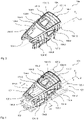
- the head section 104 comprises a vehicle head structure 104.1 which in turn comprises an interior head framework structure in the form of a head framework 104.2 (see Figure 2 , 3 and 4 ) and an outer head shell structure in the form of an outer head shell 104.3 (see Figure 5 ).
- the interior head framework 104.2 comprises two main longitudinal beams 104.4 extending, in the longitudinal direction (x-direction), from a front end to a rear end of the head framework 104.2.
- These main longitudinal beams 104.4 provide proper support of loads acting in the longitudinal direction (such as e.g. impact loads in a crash situation) against the adjacent main body section 105.
- the two main longitudinal beams 104.4 are located at an upper side of the vehicle head structure 104.1 to provide structural stability in this area.
- the two main longitudinal beams 104.4 in the mounted state of the vehicle head structure 104.1, are connected in the transverse direction (y-direction) via a plurality of transverse beams including a frontal first transverse beam 104.5 (carrying a wiper box receiving the drive unit for a wiper for the front window of the head section 104) and a second transverse beam 104.6, all welded to the main longitudinal beams 104.4 to provide good structural stability of the configuration.
- the first and second transverse beam 104.5, 104.6 and the two longitudinal beams 104.4 form part of a front window frame for a front window unit 107 (see Figure 5 ) of the head section 104.
- the head framework 104.2 comprises at a plurality of lateral main pillar elements including two center main pillar elements 104.8 as well as two rearward main pillar elements 104.9, all welded to the main longitudinal beams 104.4 to provide good structural stability of the configuration.
- the two center main pillar elements 104.8 are located in a substantially common plane (parallel to the yz-plane) with the second transverse beam 104.6 such that an arc shaped structure is formed.
- the head framework 104.2 comprises a plurality of auxiliary pillar elements 104.10 (firmly connected to the main longitudinal beams 104.4 to provide proper support to the outer shell 104.3 of the head section 104) and auxiliary beams 104.11 as well as further elements such as side window frames etc.
- the auxiliary pillar elements 104.10 are mutually interconnected and connected to adjacent main pillar elements 104.8, 104.9, among others, by auxiliary longitudinal beam elements 104.12 to provide an overall structurally stable framework.
- the auxiliary beams 104.11 are firmly connected, e.g. welded, to a (generally quadrangular) frame element 104.7 which itself is firmly connected, e.g. glued, to the main longitudinal beams 104.4, the second transverse beam 104.6 and the main body section 105 to provide proper support to the outer shell 104.3 in the top part of the head section 104.
- a third transverse beam 104.13 (sitting underneath one of the auxiliary beams 104.11) is located in a substantially common plane (parallel to the yz-plane) with the rearward lateral main pillar elements 104.9 and connected to the main longitudinal beams 104.4 such that, here as well, an arc shaped structure is formed.
- the third transverse beam 104.13 is connected to the longitudinal beams 104.4 by a cold joining process, such as riveting. It will be appreciated however that, with other embodiments of the invention, any other cold joining technique may be used, such as e.g. screwing, clamping but also gluing etc.
- a mounting access opening 108 within the head framework 104.2 and the outer head shell 104.3 of the head section is used for introducing large and heavy components into the vehicle interior prior to closing the outer head shell 104.3 of the head section 104, thereby facilitating overall assembly and manufacture of the vehicle.
- the mounting access opening 108 is delimited by the main longitudinal beams 104.4, the second transverse beam 104.6 and an interface profile (not shown in greater detail) of the main body section 105 (forming an interface for the frame 104.7).
- a cover unit 104.15 including the frame 104.7, the auxiliary transverse beams 104.11 and the outer shell element 104.14 (as well as, for example, a head light module as indicated in Figure 3 to 5 ) may be inserted (as a pre-assembled module) and connected to the main longitudinal beams 104.4, the second transverse beam 104.6 and the rear transverse interface (not shown in greater detail) of the main body section 105 forming the interface for frame 104.7.
- a cold joining process is used to avoid distortion of the structure due to heat (as it would be the case, for example, if a welding process was used).
- the frame 104.7 of the cover unit 104.15 is glued onto the respective interfaces to firmly connect the cover unit 104.15 to the structure.
- the opening provided by the front window frame may also be used for inserting equipment into the vehicle interior prior to mounting the front window unit 107.
- connection of the front window unit 107 is preferably executed in a cold joining process.
- the front window unit 107 is glued into the front window frame.
- the main body section 105 comprises a bottom structure 105.1 protruding, in the longitudinal direction, into the head section 104.
- the front end of the bottom structure 105.1 carries a substantially plate shaped frontal barrier unit in the form of the so-called barrier plate 109.
- the plane of main extension of the barrier plate 109 is arranged to be substantially parallel to the yz-plane.
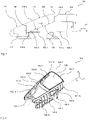
- the barrier plate 109 (which is at least connected to the main body section 105 but can additionally cover the front of the internal head framework) is adapted to carry an impact energy absorbing unit comprising one or more impact energy absorbing devices (as is indicated by the dashed contour 110 in Figure 1 ).
- the impact energy absorbing unit serves to absorb impact energy in a crash situation with a crash partner (e.g. another vehicle or an obstacle).
- the mechanical interface 106 between the head section 104 and the main body section 105 is formed by the head interface section 106.1 and the mating main body interface section 106.2 partially extending obliquely to both the longitudinal direction and the height direction.
- the head interface section 106.1 forms a stepped interface which, in an inclined, downward facing first section 106.3, is inclined with respect to the height direction (z-axis) and the longitudinal direction (x-axis).
- a second section 106.4 and a third section 106.5 of the interface section 106.1, both located adjacent to the first section 106.3 are substantially parallel to the height direction (z-axis), while a fourth section 106.6 of the interface section 106.1 located adjacent to the third section 106.5 is inclined with respect to the height direction (z-axis) but parallel to the longitudinal direction (x-axis).
- the respective sections 106.3 to 106.6 of the head interface section 106.1 define substantially planar interface surfaces.
- the interface surfaces may be substantially parallel with respect to the transverse direction (y-direction) leading to fully planar interface surfaces.
- the interface surface is selected such that, at each edge point of the interface edge formed at the intersection of the outer shell 104.3 and the interface surface, the tangential plane of interface surface (i.e., the plane tangent to the interface surface at this edge point) contains the surface normal of the outer shell 104.3 at the respective edge point as well as the tangent line (tangent to the interface edge at this edge point).
- the head interface section in any of its sections, in particular, in the inclined first section, does not necessarily have to show a substantially planar interface surface. More precisely, the interface surface defined by the respective interface section may be an at least section wise angled surface and/or an at least section wise curved surface.
- a tangential interface plane i.e. a plane that is tangent to the interface surface, in the present example, coincides with the respective interface surface.
- This partially oblique interface 106 has the advantage that the split line between the head section 104 and the main body section 105, at the individual longitudinal level, may be placed at the height level where, for example, the part of the vehicle outer shell located below this height level still continues the prismatic (two-dimensionally shaped) outer surface of the main body section while, the part of the vehicle outer shell located above this height level already forms part of a complex (three-dimensionally shaped) part of the head section.
- the (at least partially) inclined or oblique interface 106 in other words, in a highly beneficial way allows separating the complex three-dimensionally shaped part of the outer surface and the greatly less complex two dimensionally shaped part of the outer surface such that the head section 104 does not necessarily have any such prismatic areas.
- the size of the head section 104 may be reduced and limited only to the complex three-dimensionally shaped part of the outer surface. This greatly facilitates manufacture of the head section 104.
- the prismatic areas located at the same longitudinal level may be formed together with the main body section 105 in a way simpler manufacturing process (e.g. even in an extrusion process). Thus, manufacture of the overall structure is greatly facilitated.
- the at least partially inclined or oblique interface 106 has the advantage that, compared to conventional vertically arranged interfaces, (nonetheless due to the increased interface area and the advantageous special arrangement) it provides a way better support to both loads in the height direction (such as e.g. gravitational loads) and torsional loads of the vehicle body structure 102 about the longitudinal direction.
- loads in the height direction such as e.g. gravitational loads
- torsional loads of the vehicle body structure 102 about the longitudinal direction.
- the overall expense for the interface section 106 may be reduced compared to conventional designs.
- a bottom part of the main body section 105 in the longitudinal direction, extends below the vehicle head structure 104.1 over 75% to 95%, more precisely about 85%, of the longitudinal dimension of the vehicle head structure 104.1 (between the end plate 109 and the second interface section 106.4).
- the bottom part of the main body section 105 may extend over different fractions of the longitudinal dimension of the vehicle head structure 104.1.
- the bottom part of the main body section 105 extends below the vehicle head structure 104.1 over at least 30%, more preferably over at least 50%, even more preferably over substantially 100%, of the longitudinal dimension of the vehicle head structure 104.1.
- the inclined first section 106.3 may extend over an arbitrary fraction of the total length (i.e. dimension in the longitudinal direction) and/or an arbitrary fraction of the total height (i.e. dimension in the height direction) of the head section 104.
- the inclined first section 106.3 may even extend over the total length and/or total height of the head section 104.
- the inclined first section 106.3 may extend (either from the upper vertex of the head section 104 or, in an angled split line configuration, from an upper split line section similar to second section 106.4) down to the bottom structure 105.1, in particular, in some cases reaching up to the forward end of the bottom structure 105.1 (i.e. up to the end plate 109).
- the location and dimension of the inclined section 106.3 may be selected as a function of the outlay of the head section 104, in particular, at the transition between the prismatic, two-dimensionally shaped outer surface areas and the complex three dimensionally shaped outer surface areas.
- the obliauelv inclined section 106.3 in the height direction, extends substantially down to the interior floor level defined by the bottom structure 105.1.
- a plurality of mutually spaced inclined sections may be provided. These inclined sections may, for example, alternate with one or more intermediate sections extending parallel to the height direction or, eventually, parallel to the longitudinal direction.
- the lateral main pillar elements104.8 and 104.9 protrude beyond the interface 106.1 to provide a connector element reaching into the main body section 105.
- the lateral main pillar elements104.8 and 104.9 reach down to the bottom structure 105.1 of the main body section 105 and are firmly connected to the bottom structure 105.1.
- the arc shaped structure formed by the coplanar center main pillar elements 104.8 and the second transverse beam 104.6 is closed via the bottom structure 105.1 ultimately yielding a ring-shaped, highly stable structure.
- the arc shaped structure formed by the third transverse beam 104.13 and the rearward lateral main pillar elements 104.9 are the same applies.
- the frontal impact energy absorbing unit 110 is adapted to absorb the entire maximum impact energy to be taken by the vehicle 101 under given crash scenarios (e.g. prescribed according to national, international or operator regulations). Furthermore, the head framework 104.2 is adapted to undergo substantially no plastic deformation in this maximum frontal crash scenario. Obviously, this is beneficial in terms of protecting a driver and vital components of the vehicle 101 located in the head section in such a crash situation.
- the auxiliary framework elements (such as the auxiliary pillar element 104.10 shown in Figure 6 ) and the main framework elements (such as the main pillar element 104.8 shown in Figure 6 ) support a head shell structure 104.16 forming part of an outer shell of the head section.
- a beneficial support of the outer shell of the vehicle particularly against high aerodynamic loads (as they occur, for example, particularly in high-speed operations, at the entrance into a tunnel or an encounter with a passing vehicle) is achieved.
- the head shell structure 104.16 comprises a plurality of elongated reinforcement elements 104.17 connected and extending transverse to the auxiliary pillar elements 104.10 and connected to an outer shell element 104.18, thereby beneficially increasing structural stability of the outer shell.
- the reinforcement elements 104.17 preferably are monolithically formed with the outer shell element 104.18 (e.g. both generated in a common extrusion process).
- any other connecting technique preferably cold bonding technique (to avoid heat induced distortion), may also be used.
- the outer shell element 104.18 is connected directly to the main head framework element, thereby achieving a very beneficial introduction of loads into the head shell structure 104.16 and, ultimately, a highly structurally stable configuration.
- a nose section 111 of the wagon body 102 covers the impact energy absorbing unit 110 as well as connectors (not shown) for providing mechanical, energy and/or data transfer connection with respect to another vehicle.
- the nose section 111 may be formed as a separate component mechanically connected to the head section 104.
- the nose section 111 may also be part of the head section 104.
- the nose section may be formed in a similar manner as the head section 104.
- the vehicle head structure 104.1 is formed as a differential structure composed of a plurality of mutually mechanically connected components, thereby facilitating manufacture of the overall structure.
- At least a fraction of the components are connected at least partially in a fusion process, in particular, in a welding process.
- Such configurations typically, facilitate repair of damaged sections.
- at least a fraction of the components in particular, the components of the head framework structure 104.2 as well as the components of the outer shell structure 104.3, are made from a material comprising a light metal alloy, in particular, comprising aluminum.
- Such configurations typically, allow very lightweight structures.
- a first head sidewall framework located on one side of the head section 104 is formed in a separate manufacturing station, the first head sidewall framework comprising one of the longitudinal beams 104.4, the main pillar elements 104.8 and 104.9, the auxiliary framework elements 104.10 for this first head sidewall framework and the auxiliary longitudinal framework element 104.12.
- the second head sidewall framework located on the other side of the head section 104 and comprising the corresponding components may be formed.
- a first and second three-dimensionally shaped parts of the head shell structure 104.16 as outlined above i.e. comprising the reinforcement elements 104.17 and the outer shell element 104.18) for the respective side of the head section 104 is formed in a separate manufacturing station.
- the first part of the head shell structure 104.16 is connected to the associated first head sidewall framework (i.e. components 104.4, 104.8, 104.9, 104.10, 104.12) to form a first head sidewall while the second part of the head shell structure 104.16 is connected to the second head sidewall framework (i.e. components 104.4, 104.8, 104.9, 104.10, 104.12) to form a second head sidewall, respectively, to provide the configuration as described above in the context of Figure 6 .
- first head sidewall framework i.e. components 104.4, 104.8, 104.9, 104.10, 104.12
- each one of the first and second sidewalls is connected via the respective part of the interface 106 to an adjacent third and fourth (prismatic) main body sidewall (more precisely, a main body sidewall segment) of the main body section 105 to form a first and second vehicle side wall (more precisely, a first and second vehicle sidewall segment), respectively.
- the first and second vehicle sidewalls are connected to the bottom structure 105.1 of the main body section 105 and to a roof structure 105.2 of the main body section to form the vehicle body 102.
- the longitudinal beams 104.1 are connected via the barrier plate 109 and the transverse beams 104.5 and 104.6 to provide the configuration as described above, thereby achieving a firm and rigid connection between the two vehicle sidewalls.
- the respective head sidewall framework may be connected to the associated main body sidewall after the main body sidewall has been connected to the bottom structure 105.1 and to the roof structure 105.2 of the main body section 105.
- the first and second head sidewall framework i.e. components 104.4, 104.8, 104.9, 104.10, 104.12
- the head framework 104.2 may be pre-assembled (either alone or already with parts of the outer shell structure 104.3 mounted thereon) and then connected as a whole unit via the interface 106 to the main body section 105.
- the respective outer shell structure of the head segments and/or the main body segments may be mounted at any desired point in time prior to or after connecting the respective (head and/or main body) sidewall frameworks to each other, to the bottom structure 105.1 and/or to the roof structure 105.2.
- connecting techniques used in any of these steps may comprise any desired connecting technique or arbitrary combinations of different connecting techniques.
- at least one of these connecting techniques comprises a fusion process, in particular, a welding process.
- the large and/or heavy components are inserted into the vehicle interior via the manufacturing access opening 108 as it has been outlined above.
- the third transverse beam 104.14 is mounted in the way it has been described above.
- the frame 104.7 with the auxiliary transverse beams 104.11 and the outer shell element 104.14 forming the corresponding part of the outer shell closing the mounting access opening 108 are installed in the way it has been described above. As mentioned, this may happen by mounting a (previously manufactured) cover unit 104.15 including the frame 104.7, the auxiliary transverse beams 104.11 and the outer shell element 104.14.
Landscapes
- Engineering & Computer Science (AREA)
- Mechanical Engineering (AREA)
- Life Sciences & Earth Sciences (AREA)
- Wood Science & Technology (AREA)
- Transportation (AREA)
- Body Structure For Vehicles (AREA)
- Automatic Cycles, And Cycles In General (AREA)
- Vehicle Interior And Exterior Ornaments, Soundproofing, And Insulation (AREA)
Claims (15)
- Schienenfahrzeug, insbesondere ein Hochgeschwindigkeits-Schienenfahrzeug, mit einem Kopfabschnitt (104) und einem Hauptkörperabschnitt (105), wobei- eine Fahrzeugkopfstruktur (104.1) des Kopfabschnitts (104) einen Kopfschnittstellenabschnitt (106.1) aufweist, der eine mechanische Schnittstelle zu einem passenden Hauptkörperschnittstellenabschnitt des Hauptkörperabschnitts (105) bildet;- die Fahrzeugkopfstruktur (104.1) eine Längsrichtung, eine Querrichtung und eine Höhenrichtung definiert;- die Fahrzeugkopfstruktur (104.1) derart ausgebildet ist, dass sich, in einem montierten Zustand, ein Bodenteil des Hauptkörperabschnitts (105) in der Längsrichtung unterhalb der Fahrzeugkopfstruktur (104.1) erstreckt,dadurch gekennzeichnet, dass- die Fahrzeugkopfstruktur (104.1) eine Innenrahmenstruktur (104.2) aufweist, die wenigstens zwei Längsträger (104.4) umfasst, die sich in der Längsrichtung von einem vorderen Ende zu einem hinteren Ende der inneren Rahmenstruktur (104.2) erstrecken und über wenigstens einen Querträger (104.6) verbunden sind,- die beiden Längsträger (104.4) und der Querträger (104.6) eine Montagezugangsöffnung (108) begrenzen, die, in Längsrichtung, zwischen dem Querträger (104.6) und dem hinteren Ende der Innenrahmenstruktur (104.2) angeordnet ist,- wobei die Montagezugangsöffnung (108) während der Herstellung des Fahrzeugs zum Einsetzen großer Innenausstattungskomponenten in einen Innenraum des Kopfteils (104) verwendbar ist;- wobei die Montagezugangsöffnung (108) teilweise durch einen weiteren Querträger (104.13) verschlossen ist, der mit den Längsträgern (104.4) in einem Kaltfügeverfahren, insbesondere in einem Nietverfahren, verbunden ist;- wobei die Montagezugangsöffnung (108) durch eine Abdeckeinheit (104.15) verschlossen ist, die einen Teil einer Außenschale der Fahrzeugkopfstruktur (104.1) bildet.
- Schienenfahrzeug nach Anspruch 1, wobei- der Kopfschnittstellenabschnitt (106.1) wenigstens einen geneigten ersten Abschnitt (106.3) umfasst, der in Bezug auf die Höhenrichtung und die Längsrichtung geneigt ist,
wobei- der Kopfschnittstellenabschnitt (106.1) insbesondere eine Schnittstellenfläche definiert, wobei die Schnittstellenfläche eine tangentiale Schnittstellenebene definiert, wobei die tangentiale Schnittstellenebene tangential zu der Schnittstellenfläche ist;- wobei die Schnittstellenebene, in dem wenigstens einen geneigten ersten Abschnitt (106.3), eine erste Neigung in Bezug auf die Höhenrichtung aufweist, wobei die erste Neigung insbesondere im Bereich von 5° bis 85°, vorzugsweise von 30° bis 80°, weiter vorzugsweise von 60° bis 70° liegt;
und/oder- die Schnittstellenfläche in der Höhenrichtung nach unten in Richtung einer Spur, auf der das Fahrzeug fährt, weist. - Schienenfahrzeug nach Anspruch 2, wobei- die Schnittstellenebene im Wesentlichen parallel zur Querrichtung verläuft;
und/oder- die Schnittstellenebene, in wenigstens einem zweiten Abschnitt, der an den geneigten ersten Abschnitt (106.3) angrenzt, im Wesentlichen parallel zu der Höhenrichtung oder im Wesentlichen parallel zu der Längsrichtung verläuft;
und/oder- die Schnittstellenfläche, in einer Ebene parallel zu der Höhenrichtung und der Längsrichtung, eine abgestufte Schnittstellenkontur definiert. - Schienenfahrzeug nach einem der Ansprüche 2 oder 3, wobei- das Schienenfahrzeug im Bereich des Kopfabschnitts (104) eine Bodenstruktur (105.1) aufweist, die ein Innenraumbodenniveau und eine maximale Höhenabmessung über dem Innenraumbodenniveau in der Höhenrichtung definiert;- wobei sich der wenigstens eine geneigte Abschnitt, in der Höhenrichtung, über 10 % bis 90 % der maximalen Höhenabmessung, vorzugsweise über 25 % bis 75 % der maximalen Höhenabmessung, weiter vorzugsweise über 40 % bis 65 % der maximalen Höhenabmessung erstreckt;
und/oder- wobei sich der wenigstens eine geneigte erste Abschnitt (106.3), in der Höhenrichtung, im Wesentlichen bis zu dem Innenraumbodenniveau erstreckt. - Schienenfahrzeug nach einem der Ansprüche 1 bis 4, wobei- die Innenrahmenstruktur (104.2) eine Frontalbarriereeinheit (109) umfasst, die ausgelegt ist, wenigstens eine Aufprallenergieabsorptionsvorrichtung (110) zu tragen, wobei die Frontalbarriereeinheit (109) insbesondere eine im Wesentlichen plattenförmige Einheit ist;
und/oder- das Fahrzeug derart ausgelegt ist, dass es in einem definierten maximalen Frontalcrashszenario eine maximale Frontalaufprallbelastung erfährt, wobei die innere Rahmenstruktur (104.2) derart ausgelegt ist, dass sie in dem maximalen Frontalcrashszenario im Wesentlichen keine plastische Verformung erfährt;
und/oder- die Innenrahmenstruktur (104.2) wenigstens ein seitliches Hauptsäulenelement (104.8, 104.9) umfasst, wobei das seitliche Hauptsäulenelement (104.8, 104.9), in der Höhenrichtung, über den Schnittstellenabschnitt (106.3) hinausragt, um ein Verbindungselement bereitzustellen, das in den Hauptkörperabschnitt (105) hineinreicht, insbesondere bis zu einer Bodenstruktur (105.1) des Hauptkörperabschnitts (105);
und/oder- die Innenrahmenstruktur (104.2) wenigstens zwei seitliche Hauptsäulenelemente (104.8, 104.9) aufweist, die in einer gemeinsamen Ebene angeordnet und in der Querrichtung über einen Querträger (104.6, 104.13) verbunden sind, um eine bogenförmige Hauptstützstruktur der inneren Rahmenstruktur (104.2) zu bilden, wobei sich die seitlichen Hauptsäulenelemente (104.8, 104.9) insbesondere in der Höhenrichtung bis zu einer Bodenstruktur (105.1) des Hauptkörperabschnitts (105) erstrecken;
und/oder- die beiden Längsträger (104.4) an einer Oberseite der Kopfstruktur angeordnet sind;
und/oder- der Querträger (104.6) und die beiden Längsträger (104.4) einen Teil eines Frontscheibenrahmens des Kopfteils (104) bilden;
und/oder- die Innenrahmenstruktur (104.2) eine Vielzahl von Hilfssäulenelementen (104.10) und/oder eine Vielzahl von Hilfsträgern (104.11) umfasst, die eine Schalenstruktur (104.3) tragen, die eine äußere Schale des Kopfteils (104) bildet, wobei die Schalenstruktur (104.3) insbesondere eine Vielzahl von länglichen Verstärkungselementen (104.17) umfasst, die mit den Hilfssäulenelementen (104.10) und/oder den Hilfsträgern (104.11) verbunden sind;
und/oder- die Innenrahmenstruktur (104.2) eine Vielzahl von Hauptrahmenelementen (104.4, 104.6, 104.8, 104.9, 104.13) und eine Vielzahl von Hilfsrahmenelementen (104.10, 104.11) umfasst, die eine äußere Schalenstruktur (104.3) tragen, die ein äußeres Schalenelement (104.18), das eine äußere Schale des Kopfabschnitts (104) bildet, und eine Vielzahl von länglichen Verstärkungselementen (104. 17), die mit dem Außenschalenelement (104.18) verbunden sind, wobei die Verstärkungselemente (104.17) mit den Hilfsrahmenelementen (104.10, 104.11) verbunden sind und das Außenschalenelement (104.18) direkt mit den Hauptrahmenelementen (104.4, 104.6, 104.8, 104.9, 104.13) verbunden ist. - Schienenfahrzeug nach einem der Ansprüche 1 bis 5, wobei- im montierten Zustand, der Bodenteil des Hauptkörperabschnitts (105), in der Längsrichtung, über wenigstens 30 %, vorzugsweise über wenigstens 50 %, weiter vorzugsweise über im Wesentlichen 100 % einer Längsabmessung der Fahrzeugkopfstruktur (104.1) verläuft.
- Schienenfahrzeug nach einem der Ansprüche 1 bis 6, wobei- die Fahrzeugkopfstruktur (104.1) als eine Differentialstruktur ausgebildet ist, die aus einer Vielzahl von mechanisch miteinander verbundenen Komponenten (104.4 bis 104.18) besteht;- wobei wenigstens ein Teil der Komponenten (104.4 bis 104.12, 104.16 bis 104.18) zumindest teilweise in einem Schmelzverfahren, insbesondere in einem Schweißverfahren, verbunden ist;
und/oder- wenigstens ein Teil der Komponenten (104.4 bis 104.18) aus einem Material hergestellt ist, das eine Leichtmetalllegierung, insbesondere Aluminium, umfasst. - Schienenfahrzeug nach einem der Ansprüche 1 bis 7, wobei das Schienenfahrzeug für einen Hochgeschwindigkeitsbetrieb mit Nennbetriebsgeschwindigkeiten über 250 km/h, vorzugsweise über 300 km/h, weiter vorzugsweise über 350 km/h, ausgelegt ist.
- Wagenkastenstruktur eines Schienenfahrzeugs, insbesondere des Schienenfahrzeugs nach einem der Ansprüche 1 bis 7, umfassend- eine Fahrzeugkopfstruktur (104.1), die einen Kopfabschnitt (104) der Fahrzeugkörperstruktur bildet, und eine Hauptkörperstruktur, die einen Hauptkörperabschnitt (105) der Fahrzeugkörperstruktur bildet;- wobei der Hauptkörperabschnitt (105) insbesondere eine im Wesentlichen prismatische Außenfläche entlang der Längsrichtung aufweist;
wobei- eine Fahrzeugkopfstruktur (104.1) des Kopfabschnitts (104) einen Kopfschnittstellenabschnitt (106.1) aufweist, der eine mechanische Schnittstelle zu einem passenden Hauptkörperschnittstellenabschnitt des Hauptkörperabschnitts (105) bildet;- die Fahrzeugkopfstruktur (104.1) eine Längsrichtung, eine Querrichtung und eine Höhenrichtung definiert;- die Fahrzeugkopfstruktur (104.1) derart ausgebildet ist, dass sich, in einem montierten Zustand, ein Bodenteil des Hauptkörperabschnitts (105) in der Längsrichtung unterhalb der Fahrzeugkopfstruktur (104.1) erstreckt,- wobei der Hauptkörperabschnitt (105) insbesondere eine Bodenstruktur (105.1) umfasst, die ein Innenbodenniveau definiert und, in der Längsrichtung, in den Kopfabschnitt (104) hineinreichtdadurch gekennzeichnet, dass- die Fahrzeugkopfstruktur (104.1) eine Innenrahmenstruktur (104.2) aufweist, die wenigstens zwei Längsträger (104.4) umfasst, die sich in der Längsrichtung von einem vorderen Ende zu einem hinteren Ende der Innenrahmenstruktur (104.2) erstrecken und über wenigstens einen Querträger (104.6) verbunden sind,- die beiden Längsträger (104.4) und der Querträger (104.6) eine Montagezugangsöffnung (108) begrenzen, die, in Längsrichtung, zwischen dem Querträger (104.6) und dem hinteren Ende der Innenrahmenstruktur (104.2) angeordnet ist,- wobei die Montagezugangsöffnung (108) während der Herstellung des Fahrzeugs zum Einsetzen großer Innenausstattungskomponenten in einen Innenraum des Kopfteils (104) verwendbar ist;- wobei die Montagezugangsöffnung (108) teilweise durch einen weiteren Querträger (104.13) verschlossen ist, der mit den Längsträgern (104.4) in einem Kaltfügeverfahren, insbesondere in einem Nietverfahren, verbunden ist;- wobei die Montagezugangsöffnung (108) durch eine Abdeckeinheit (104.15) verschlossen ist, die einen Teil einer Außenschale der Fahrzeugkopfstruktur (104.1) bildet. - Verfahren zur Herstellung der Fahrzeugkörperstruktur nach Anspruch 9, umfassend,- in einem ersten Schritt eines Seitenwandbildungsschritts unter Verwendung wenigstens einer ersten Verbindungstechnik einen ersten Kopfseitenwandrahmen des Kopfabschnitts (104) gebildet wird, wobei der erste Kopfseitenwandrahmen einen ersten Längsträger (104.4) und/oder ein erstes Hauptsäulenelement (104.8, 104.9) und/oder eine Vielzahl von ersten Hilfsrahmenelementen (104.10, 104.12) umfasst,- in einem Fahrzeugkörper-Montageschritt unter Verwendung wenigstens einer zweiten Verbindungstechnik, Verbinden einer ersten Fahrzeugseitenwand mit einer Bodenstruktur (105.1) des Hauptkörperabschnitts (105) und insbesondere mit einer Dachstruktur des Hauptkörperabschnitts (105), um einen Fahrzeugkörper zu bilden;- wobei der erste Kopfseitenwandrahmen in die erste Fahrzeugseitenwand vor oder innerhalb des Fahrzeugkörper-Montageschritts integriert wird;- wobei wenigstens eine aus der ersten Verbindungstechnik und der zweiten Verbindungstechnik insbesondere ein Schmelzverfahren, insbesondere ein Schweißverfahren, umfasst.
- Verfahren nach Anspruch 10, wobei- in einem zweiten Schritt des Seitenwandbildungsschritts unter Verwendung wenigstens einer dritten Verbindungstechnik der erste Kopfseitenwandrahmen mit einer Hauptkörperseitenwand des Hauptkörperabschnitts (105) verbunden wird, um die erste Fahrzeugseitenwand zu bilden, und die erste Fahrzeugseitenwand mit der Bodenstruktur (105.1) verbunden wird;
oder- in Fahrzeugkörper-Montageschritt unter Verwendung wenigstens einer dritten Verbindungstechnik, Verbinden einer Hauptkörperseitenwand des Wagenkörpers mit der Bodenstruktur (105.1) und anschließendes Verbinden des ersten Kopfseitenwandrahmens mit der Hauptkörperseitenwand, um die erste Fahrzeugseitenwand zu bilden;- wobei die dritte Verbindungstechnik insbesondere ein Schmelzverfahren, insbesondere ein Schweißverfahren, umfasst. - Verfahren nach Anspruch 10 oder 11, wobei- in dem Fahrzeugkörper-Montageschritt unter Verwendung einer vierten Verbindungstechnik ein zweiter Längsträger (104.4) eines zweiten Kopfseitenwandrahmens mit dem ersten Längsträger (104.4) über einen ersten Querträger (104.6) verbunden wird, der sich in der Querrichtung erstreckt;- wobei der erste Längsträger (104.4) und der zweite Längsträger (104.4) insbesondere an einer Oberseite der Kopfstruktur angeordnet sind;- wobei der erste Längsträger (104.4), der zweite Längsträger (104.4) und der erste Querträger (104.6) insbesondere einen Teil eines Frontscheibenrahmens einer Frontscheibenöffnung des Kopfteils (104) bilden;- wobei der erste Längsträger (104.4), der zweite Längsträger (104.4) und der erste Querträger (104.6) insbesondere eine Montagezugangsöffnung (108) begrenzen, die in der Längsrichtung zwischen dem Querträger (104.6) und einem hinteren Ende des Kopfabschnitts (104) angeordnet ist, wobei die Montagezugangsöffnung (108) zum Einsetzen großer Innenausstattungskomponenten in einen Innenraum des Kopfabschnitts (104) verwendbar ist;- wobei der erste Querträger (104.6) insbesondere in einer im Wesentlichen gemeinsamen Ebene mit einem ersten seitlichen Hauptsäulenelement (104.8), das mit dem ersten Längsträger (104.4) verbunden ist, und einem zweiten seitlichen Hauptsäulenelement (104.8), das mit dem zweiten Längsträger (104. 4) verbunden ist, um eine bogenförmige Hauptstützstruktur zu bilden, wobei sich das erste seitliche Hauptsäulenelement (104.8) und das zweite seitliche Hauptsäulenelement (104.8) insbesondere in der Höhenrichtung bis zu der Bodenstruktur (105.1) erstrecken und insbesondere mit der Bodenstruktur (105.1) verbunden sind;- wobei die vierte Verbindungstechnik insbesondere ein Schmelzverfahren, insbesondere ein Schweißverfahren, umfasst.
- Verfahren nach Anspruch 12, wobei- in dem Fahrzeugkörper-Montageschritt, wenigstens eine große Innenausstattungskomponente über die Montagezugangsöffnung (108) und/oder die Frontscheibenöffnung in den Innenraum des Kopfteils (104) eingesetzt wird, wobei es sich bei der Innenausstattungskomponente insbesondere um ein Fahrerpult, einen Schaltschrank für elektrische Geräte oder einen Kabelkanal handelt;- in dem Fahrzeugkörper-Montageschritt, nach dem Einsetzen der Innenausstattungskomponente und unter Verwendung einer fünften Verbindungstechnik, die Montagezugangsöffnung (108) insbesondere teilweise durch einen zweiten Querträger (104.13) verschlossen wird, der mit dem ersten Längsträger (104.4) und dem zweiten Längsträger (104.4) verbunden ist;- in dem Fahrzeugkörper-Montageschritt, nach dem Einsetzen der Innenausstattungskomponente und unter Verwendung einer sechsten Verbindungstechnik, die Frontscheibenöffnung, insbesondere durch eine Frontscheibeneinheit (107), geschlossen wird;- in dem Fahrzeugkörper-Montageschritt, nach dem Einsetzen der Innenausstattungskomponente und unter Anwendung einer siebten Verbindungstechnik, die Montagezugangsöffnung (108) insbesondere durch eine Abdeckeinheit (104.15) verschlossen wird, die einen Teil einer Außenschale des Fahrzeugkopfabschnitts (104) bildet;- wobei die fünfte Verbindungstechnik insbesondere ein Kaltfügeverfahren, insbesondere ein Nietverfahren, umfasst;- wenigstens eine aus die sechste Verbindungstechnik und die siebte Verbindungstechnik, insbesondere ein Fügeverfahren, insbesondere ein adhäsives Verbindungsverfahren, vorzugsweise ein Klebeverfahren, umfasst.
- Verfahren nach einem der Ansprüche 10 bis 13, wobei- in dem Seitenwandbildungsschritt eine Kopfschalenstruktur (104.3), die einen Teil einer Außenschale des Kopfabschnitts (104) bildet, mit dem ersten Kopfseitenwandrahmen verbunden wird;
oder- in einem Außenschalenbildungsschritt, nach dem Seitenwandbildungsschritt, eine Kopfschalenstruktur (104.3), die einen Teil einer Außenschale des Kopfabschnitts (104) bildet, mit der ersten Fahrzeugseitenwand verbunden wird;- wobei die Kopfschalenstruktur (104.3) insbesondere eine Vielzahl von länglichen Verstärkungselementen (104.17) umfasst, die mit Hilfselementen des ersten Kopfseitenwandrahmens verbunden sind; - Verfahren zur Herstellung der Fahrzeugkörperstruktur nach Anspruch 9, umfassend- teilweises Formen des Kopfabschnitts (104) und des Hauptkörperabschnitts (105), wobei die Montagezugangsöffnung (108) innerhalb des Kopfabschnitts (104) offen gelassen wird, um große Innenausstattungskomponenten in einen Innenraum des Kopfabschnitts (104) einzuführen;- Einführen der großen Innenausstattungskomponenten in das Innere des Kopfabschnitts (104) über die Montagezugangsöffnung (108); und- Schließen der wenigstens einen Montagezugangsöffnung (108) unter Verwendung der Abdeckeinheit (104.15), um den Teil der Außenschale des Fahrzeugkopfabschnitts (104) zu bilden.
Applications Claiming Priority (1)
| Application Number | Priority Date | Filing Date | Title |
|---|---|---|---|
| PCT/EP2013/055584 WO2014146681A1 (en) | 2013-03-18 | 2013-03-18 | Vehicle structure for a rail vehicle |
Publications (2)
| Publication Number | Publication Date |
|---|---|
| EP2976244A1 EP2976244A1 (de) | 2016-01-27 |
| EP2976244B1 true EP2976244B1 (de) | 2023-01-25 |
Family
ID=47913411
Family Applications (1)
| Application Number | Title | Priority Date | Filing Date |
|---|---|---|---|
| EP13711020.1A Active EP2976244B1 (de) | 2013-03-18 | 2013-03-18 | Fahrzeugstruktur für ein schienenfahrzeug |
Country Status (4)
| Country | Link |
|---|---|
| EP (1) | EP2976244B1 (de) |
| CN (1) | CN105102294B (de) |
| ES (1) | ES2939961T3 (de) |
| WO (1) | WO2014146681A1 (de) |
Families Citing this family (7)
| Publication number | Priority date | Publication date | Assignee | Title |
|---|---|---|---|---|
| DE102016208693A1 (de) * | 2016-05-20 | 2017-11-23 | Siemens Aktiengesellschaft | Fahrzeug, insbesondere Schienenfahrzeug |
| CN109625014A (zh) * | 2018-12-12 | 2019-04-16 | 中车青岛四方机车车辆股份有限公司 | 一种轨道车辆的车头结构 |
| EP3741641A4 (de) * | 2019-02-26 | 2022-04-06 | CRRC Changchun Railway Vehicles Co., Ltd. | Lokomotivenaufbau für elektrische mehrfacheinheit |
| CN110732798B (zh) * | 2019-11-11 | 2021-03-16 | 中车长春轨道客车股份有限公司 | 动车组头车侧墙倾角的加工方法 |
| CN112660178B (zh) * | 2021-01-18 | 2022-11-18 | 中车青岛四方机车车辆股份有限公司 | 司机室及司机室的组装方法 |
| CN112622945B (zh) * | 2021-01-18 | 2022-05-27 | 中车青岛四方机车车辆股份有限公司 | 司机室内饰结构、司机室、轨道车辆及组装方法 |
| CN112622950A (zh) * | 2021-01-18 | 2021-04-09 | 中车青岛四方机车车辆股份有限公司 | 司机室骨架结构、司机室及轨道车辆 |
Family Cites Families (6)
| Publication number | Priority date | Publication date | Assignee | Title |
|---|---|---|---|---|
| DE4442263A1 (de) * | 1994-11-28 | 1996-05-30 | Fritz Prof Dr Ing Frederich | Stoßdynamische Fahrzeugkontur |
| EP0838384B1 (de) * | 1996-10-23 | 2003-04-02 | Bombardier Transportation GmbH | Fahrzeugkasten eines Schienenfahrzeuges und Schienenfahrzeug mit einem derartigen Fahrzeugkasten |
| WO2002018189A1 (fr) * | 2000-08-28 | 2002-03-07 | Mitsubishi Heavy Industries, Ltd. | Structure de corps |
| DE102006044397A1 (de) * | 2006-09-18 | 2008-03-27 | Bombardier Transportation Gmbh | Kopfmodul für ein Schienenfahrzeug |
| FR2917042B1 (fr) | 2007-06-07 | 2009-12-04 | Alstom Transport Sa | Cabine de conduite de train comprenant une verriere. |
| ES2453047T5 (es) * | 2010-04-29 | 2017-07-24 | Bombardier Transportation Gmbh | Cabeza de vehículo con sensibilidad reducida al viento lateral |
-
2013
- 2013-03-18 EP EP13711020.1A patent/EP2976244B1/de active Active
- 2013-03-18 CN CN201380074899.5A patent/CN105102294B/zh active Active
- 2013-03-18 WO PCT/EP2013/055584 patent/WO2014146681A1/en not_active Ceased
- 2013-03-18 ES ES13711020T patent/ES2939961T3/es active Active
Also Published As
| Publication number | Publication date |
|---|---|
| ES2939961T3 (es) | 2023-04-28 |
| EP2976244A1 (de) | 2016-01-27 |
| CN105102294B (zh) | 2019-03-01 |
| WO2014146681A1 (en) | 2014-09-25 |
| CN105102294A (zh) | 2015-11-25 |
Similar Documents
| Publication | Publication Date | Title |
|---|---|---|
| WO2014146681A1 (en) | Vehicle structure for a rail vehicle | |
| US11958533B2 (en) | Multi-beam side frame assembly | |
| CN1161251C (zh) | 汽车的承载结构 | |
| CN101138981B (zh) | 轨道车辆 | |
| US8459728B2 (en) | Vehicle front portion structure | |
| US20160272248A1 (en) | Vehicle body bottom structure | |
| KR20140031293A (ko) | 철도 차량 차체와 그 제조 방법 | |
| KR20050051651A (ko) | 대형 부분 모듈로 구성된 지지구조를 포함하는 차량 몸체 | |
| CN104554099A (zh) | 用于机动车的保险杠横梁 | |
| US20140150688A1 (en) | Railcar | |
| CN102066179A (zh) | 铁道车辆结构体的构造 | |
| CN107021136A (zh) | 车身前部结构 | |
| CN207292141U (zh) | 结构加强构件、结构上加强车辆的组件及结构加强组件 | |
| CN117657316B (zh) | 一种车身框架总成及车辆 | |
| CN110466611A (zh) | 一种电动汽车的后机舱总成及车身骨架 | |
| CN218858529U (zh) | 车身后部桁架结构及汽车 | |
| WO2016095625A1 (zh) | 一种高速动车组及车体、端墙结构 | |
| CN102616286A (zh) | 特别用于无乘客侧的汽车仪表板的横梁 | |
| US8523251B1 (en) | Bumper fascia support assembly | |
| US20040183338A1 (en) | Vehicle body front section structure | |
| CN114348118A (zh) | 模块化车身及模块化车身制造方法 | |
| CN212401376U (zh) | 一种汽车底板结构及电动汽车 | |
| CN210852643U (zh) | 车辆的后纵梁加强结构和车辆 | |
| CN119058823B (zh) | 前机舱结构及车辆 | |
| EP3566930B1 (de) | Fahrzeugstruktur |
Legal Events
| Date | Code | Title | Description |
|---|---|---|---|
| PUAI | Public reference made under article 153(3) epc to a published international application that has entered the european phase |
Free format text: ORIGINAL CODE: 0009012 |
|
| 17P | Request for examination filed |
Effective date: 20150826 |
|
| AK | Designated contracting states |
Kind code of ref document: A1 Designated state(s): AL AT BE BG CH CY CZ DE DK EE ES FI FR GB GR HR HU IE IS IT LI LT LU LV MC MK MT NL NO PL PT RO RS SE SI SK SM TR |
|
| AX | Request for extension of the european patent |
Extension state: BA ME |
|
| RIN1 | Information on inventor provided before grant (corrected) |
Inventor name: GROBEL, JOERG Inventor name: GIESE, KONRAD |
|
| DAX | Request for extension of the european patent (deleted) | ||
| STAA | Information on the status of an ep patent application or granted ep patent |
Free format text: STATUS: EXAMINATION IS IN PROGRESS |
|
| 17Q | First examination report despatched |
Effective date: 20190103 |
|
| GRAP | Despatch of communication of intention to grant a patent |
Free format text: ORIGINAL CODE: EPIDOSNIGR1 |
|
| STAA | Information on the status of an ep patent application or granted ep patent |
Free format text: STATUS: GRANT OF PATENT IS INTENDED |
|
| INTG | Intention to grant announced |
Effective date: 20210202 |
|
| GRAJ | Information related to disapproval of communication of intention to grant by the applicant or resumption of examination proceedings by the epo deleted |
Free format text: ORIGINAL CODE: EPIDOSDIGR1 |
|
| STAA | Information on the status of an ep patent application or granted ep patent |
Free format text: STATUS: EXAMINATION IS IN PROGRESS |
|
| INTC | Intention to grant announced (deleted) | ||
| GRAP | Despatch of communication of intention to grant a patent |
Free format text: ORIGINAL CODE: EPIDOSNIGR1 |
|
| STAA | Information on the status of an ep patent application or granted ep patent |
Free format text: STATUS: GRANT OF PATENT IS INTENDED |
|
| INTG | Intention to grant announced |
Effective date: 20210811 |
|
| RAP3 | Party data changed (applicant data changed or rights of an application transferred) |
Owner name: BOMBARDIER TRANSPORTATION GMBH |
|
| GRAJ | Information related to disapproval of communication of intention to grant by the applicant or resumption of examination proceedings by the epo deleted |
Free format text: ORIGINAL CODE: EPIDOSDIGR1 |
|
| STAA | Information on the status of an ep patent application or granted ep patent |
Free format text: STATUS: EXAMINATION IS IN PROGRESS |
|
| INTC | Intention to grant announced (deleted) | ||
| GRAP | Despatch of communication of intention to grant a patent |
Free format text: ORIGINAL CODE: EPIDOSNIGR1 |
|
| STAA | Information on the status of an ep patent application or granted ep patent |
Free format text: STATUS: GRANT OF PATENT IS INTENDED |
|
| INTG | Intention to grant announced |
Effective date: 20220210 |
|
| GRAJ | Information related to disapproval of communication of intention to grant by the applicant or resumption of examination proceedings by the epo deleted |
Free format text: ORIGINAL CODE: EPIDOSDIGR1 |
|
| STAA | Information on the status of an ep patent application or granted ep patent |
Free format text: STATUS: EXAMINATION IS IN PROGRESS |
|
| INTC | Intention to grant announced (deleted) | ||
| GRAP | Despatch of communication of intention to grant a patent |
Free format text: ORIGINAL CODE: EPIDOSNIGR1 |
|
| STAA | Information on the status of an ep patent application or granted ep patent |
Free format text: STATUS: GRANT OF PATENT IS INTENDED |
|
| INTG | Intention to grant announced |
Effective date: 20220809 |
|
| GRAS | Grant fee paid |
Free format text: ORIGINAL CODE: EPIDOSNIGR3 |
|
| GRAA | (expected) grant |
Free format text: ORIGINAL CODE: 0009210 |
|
| STAA | Information on the status of an ep patent application or granted ep patent |
Free format text: STATUS: THE PATENT HAS BEEN GRANTED |
|
| RAP1 | Party data changed (applicant data changed or rights of an application transferred) |
Owner name: ALSTOM HOLDINGS |
|
| AK | Designated contracting states |
Kind code of ref document: B1 Designated state(s): AL AT BE BG CH CY CZ DE DK EE ES FI FR GB GR HR HU IE IS IT LI LT LU LV MC MK MT NL NO PL PT RO RS SE SI SK SM TR |
|
| REG | Reference to a national code |
Ref country code: GB Ref legal event code: FG4D |
|
| REG | Reference to a national code |
Ref country code: CH Ref legal event code: EP |
|
| REG | Reference to a national code |
Ref country code: AT Ref legal event code: REF Ref document number: 1545722 Country of ref document: AT Kind code of ref document: T Effective date: 20230215 Ref country code: IE Ref legal event code: FG4D |
|
| REG | Reference to a national code |
Ref country code: DE Ref legal event code: R096 Ref document number: 602013083255 Country of ref document: DE |
|
| REG | Reference to a national code |
Ref country code: SE Ref legal event code: TRGR |
|
| REG | Reference to a national code |
Ref country code: ES Ref legal event code: FG2A Ref document number: 2939961 Country of ref document: ES Kind code of ref document: T3 Effective date: 20230428 |
|
| REG | Reference to a national code |
Ref country code: LT Ref legal event code: MG9D |
|
| REG | Reference to a national code |
Ref country code: NL Ref legal event code: MP Effective date: 20230125 |
|
| PG25 | Lapsed in a contracting state [announced via postgrant information from national office to epo] |
Ref country code: NL Free format text: LAPSE BECAUSE OF FAILURE TO SUBMIT A TRANSLATION OF THE DESCRIPTION OR TO PAY THE FEE WITHIN THE PRESCRIBED TIME-LIMIT Effective date: 20230125 |
|
| PG25 | Lapsed in a contracting state [announced via postgrant information from national office to epo] |
Ref country code: RS Free format text: LAPSE BECAUSE OF FAILURE TO SUBMIT A TRANSLATION OF THE DESCRIPTION OR TO PAY THE FEE WITHIN THE PRESCRIBED TIME-LIMIT Effective date: 20230125 Ref country code: PT Free format text: LAPSE BECAUSE OF FAILURE TO SUBMIT A TRANSLATION OF THE DESCRIPTION OR TO PAY THE FEE WITHIN THE PRESCRIBED TIME-LIMIT Effective date: 20230525 Ref country code: NO Free format text: LAPSE BECAUSE OF FAILURE TO SUBMIT A TRANSLATION OF THE DESCRIPTION OR TO PAY THE FEE WITHIN THE PRESCRIBED TIME-LIMIT Effective date: 20230425 Ref country code: LV Free format text: LAPSE BECAUSE OF FAILURE TO SUBMIT A TRANSLATION OF THE DESCRIPTION OR TO PAY THE FEE WITHIN THE PRESCRIBED TIME-LIMIT Effective date: 20230125 Ref country code: LT Free format text: LAPSE BECAUSE OF FAILURE TO SUBMIT A TRANSLATION OF THE DESCRIPTION OR TO PAY THE FEE WITHIN THE PRESCRIBED TIME-LIMIT Effective date: 20230125 Ref country code: HR Free format text: LAPSE BECAUSE OF FAILURE TO SUBMIT A TRANSLATION OF THE DESCRIPTION OR TO PAY THE FEE WITHIN THE PRESCRIBED TIME-LIMIT Effective date: 20230125 |
|
| PG25 | Lapsed in a contracting state [announced via postgrant information from national office to epo] |
Ref country code: PL Free format text: LAPSE BECAUSE OF FAILURE TO SUBMIT A TRANSLATION OF THE DESCRIPTION OR TO PAY THE FEE WITHIN THE PRESCRIBED TIME-LIMIT Effective date: 20230125 Ref country code: IS Free format text: LAPSE BECAUSE OF FAILURE TO SUBMIT A TRANSLATION OF THE DESCRIPTION OR TO PAY THE FEE WITHIN THE PRESCRIBED TIME-LIMIT Effective date: 20230525 Ref country code: GR Free format text: LAPSE BECAUSE OF FAILURE TO SUBMIT A TRANSLATION OF THE DESCRIPTION OR TO PAY THE FEE WITHIN THE PRESCRIBED TIME-LIMIT Effective date: 20230426 Ref country code: FI Free format text: LAPSE BECAUSE OF FAILURE TO SUBMIT A TRANSLATION OF THE DESCRIPTION OR TO PAY THE FEE WITHIN THE PRESCRIBED TIME-LIMIT Effective date: 20230125 |
|
| REG | Reference to a national code |
Ref country code: DE Ref legal event code: R097 Ref document number: 602013083255 Country of ref document: DE |
|
| PG25 | Lapsed in a contracting state [announced via postgrant information from national office to epo] |
Ref country code: SM Free format text: LAPSE BECAUSE OF FAILURE TO SUBMIT A TRANSLATION OF THE DESCRIPTION OR TO PAY THE FEE WITHIN THE PRESCRIBED TIME-LIMIT Effective date: 20230125 Ref country code: RO Free format text: LAPSE BECAUSE OF FAILURE TO SUBMIT A TRANSLATION OF THE DESCRIPTION OR TO PAY THE FEE WITHIN THE PRESCRIBED TIME-LIMIT Effective date: 20230125 Ref country code: MC Free format text: LAPSE BECAUSE OF FAILURE TO SUBMIT A TRANSLATION OF THE DESCRIPTION OR TO PAY THE FEE WITHIN THE PRESCRIBED TIME-LIMIT Effective date: 20230125 Ref country code: EE Free format text: LAPSE BECAUSE OF FAILURE TO SUBMIT A TRANSLATION OF THE DESCRIPTION OR TO PAY THE FEE WITHIN THE PRESCRIBED TIME-LIMIT Effective date: 20230125 Ref country code: DK Free format text: LAPSE BECAUSE OF FAILURE TO SUBMIT A TRANSLATION OF THE DESCRIPTION OR TO PAY THE FEE WITHIN THE PRESCRIBED TIME-LIMIT Effective date: 20230125 Ref country code: CZ Free format text: LAPSE BECAUSE OF FAILURE TO SUBMIT A TRANSLATION OF THE DESCRIPTION OR TO PAY THE FEE WITHIN THE PRESCRIBED TIME-LIMIT Effective date: 20230125 |
|
| P01 | Opt-out of the competence of the unified patent court (upc) registered |
Effective date: 20231025 |
|
| PG25 | Lapsed in a contracting state [announced via postgrant information from national office to epo] |
Ref country code: SK Free format text: LAPSE BECAUSE OF FAILURE TO SUBMIT A TRANSLATION OF THE DESCRIPTION OR TO PAY THE FEE WITHIN THE PRESCRIBED TIME-LIMIT Effective date: 20230125 |
|
| REG | Reference to a national code |
Ref country code: BE Ref legal event code: MM Effective date: 20230331 |
|
| PLBE | No opposition filed within time limit |
Free format text: ORIGINAL CODE: 0009261 |
|
| STAA | Information on the status of an ep patent application or granted ep patent |
Free format text: STATUS: NO OPPOSITION FILED WITHIN TIME LIMIT |
|
| REG | Reference to a national code |
Ref country code: AT Ref legal event code: UEP Ref document number: 1545722 Country of ref document: AT Kind code of ref document: T Effective date: 20230125 |
|
| PG25 | Lapsed in a contracting state [announced via postgrant information from national office to epo] |
Ref country code: LU Free format text: LAPSE BECAUSE OF NON-PAYMENT OF DUE FEES Effective date: 20230318 |
|
| 26N | No opposition filed |
Effective date: 20231026 |
|
| REG | Reference to a national code |
Ref country code: IE Ref legal event code: MM4A |
|
| PG25 | Lapsed in a contracting state [announced via postgrant information from national office to epo] |
Ref country code: SI Free format text: LAPSE BECAUSE OF FAILURE TO SUBMIT A TRANSLATION OF THE DESCRIPTION OR TO PAY THE FEE WITHIN THE PRESCRIBED TIME-LIMIT Effective date: 20230125 Ref country code: IE Free format text: LAPSE BECAUSE OF NON-PAYMENT OF DUE FEES Effective date: 20230318 |
|
| PG25 | Lapsed in a contracting state [announced via postgrant information from national office to epo] |
Ref country code: BE Free format text: LAPSE BECAUSE OF NON-PAYMENT OF DUE FEES Effective date: 20230331 |
|
| PG25 | Lapsed in a contracting state [announced via postgrant information from national office to epo] |
Ref country code: BG Free format text: LAPSE BECAUSE OF FAILURE TO SUBMIT A TRANSLATION OF THE DESCRIPTION OR TO PAY THE FEE WITHIN THE PRESCRIBED TIME-LIMIT Effective date: 20230125 |
|
| PG25 | Lapsed in a contracting state [announced via postgrant information from national office to epo] |
Ref country code: BG Free format text: LAPSE BECAUSE OF FAILURE TO SUBMIT A TRANSLATION OF THE DESCRIPTION OR TO PAY THE FEE WITHIN THE PRESCRIBED TIME-LIMIT Effective date: 20230125 |
|
| PG25 | Lapsed in a contracting state [announced via postgrant information from national office to epo] |
Ref country code: CY Free format text: LAPSE BECAUSE OF FAILURE TO SUBMIT A TRANSLATION OF THE DESCRIPTION OR TO PAY THE FEE WITHIN THE PRESCRIBED TIME-LIMIT; INVALID AB INITIO Effective date: 20130318 |
|
| PG25 | Lapsed in a contracting state [announced via postgrant information from national office to epo] |
Ref country code: HU Free format text: LAPSE BECAUSE OF FAILURE TO SUBMIT A TRANSLATION OF THE DESCRIPTION OR TO PAY THE FEE WITHIN THE PRESCRIBED TIME-LIMIT; INVALID AB INITIO Effective date: 20130318 |
|
| PG25 | Lapsed in a contracting state [announced via postgrant information from national office to epo] |
Ref country code: TR Free format text: LAPSE BECAUSE OF FAILURE TO SUBMIT A TRANSLATION OF THE DESCRIPTION OR TO PAY THE FEE WITHIN THE PRESCRIBED TIME-LIMIT Effective date: 20230125 |
|
| REG | Reference to a national code |
Ref country code: CH Ref legal event code: U11 Free format text: ST27 STATUS EVENT CODE: U-0-0-U10-U11 (AS PROVIDED BY THE NATIONAL OFFICE) Effective date: 20260401 |
|
| PGFP | Annual fee paid to national office [announced via postgrant information from national office to epo] |
Ref country code: SE Payment date: 20260319 Year of fee payment: 14 |
|
| PGFP | Annual fee paid to national office [announced via postgrant information from national office to epo] |
Ref country code: GB Payment date: 20260324 Year of fee payment: 14 |
|
| PGFP | Annual fee paid to national office [announced via postgrant information from national office to epo] |
Ref country code: DE Payment date: 20260319 Year of fee payment: 14 |
|
| PGFP | Annual fee paid to national office [announced via postgrant information from national office to epo] |
Ref country code: AT Payment date: 20260320 Year of fee payment: 14 |
|
| PGFP | Annual fee paid to national office [announced via postgrant information from national office to epo] |
Ref country code: IT Payment date: 20260324 Year of fee payment: 14 |
|
| PGFP | Annual fee paid to national office [announced via postgrant information from national office to epo] |
Ref country code: FR Payment date: 20260320 Year of fee payment: 14 |
|
| PGFP | Annual fee paid to national office [announced via postgrant information from national office to epo] |
Ref country code: ES Payment date: 20260427 Year of fee payment: 14 |
|
| PGFP | Annual fee paid to national office [announced via postgrant information from national office to epo] |
Ref country code: CH Payment date: 20260401 Year of fee payment: 14 |