EP2976558B1 - Doppelsitzventil mit antrieb - Google Patents
Doppelsitzventil mit antrieb Download PDFInfo
- Publication number
- EP2976558B1 EP2976558B1 EP12812835.2A EP12812835A EP2976558B1 EP 2976558 B1 EP2976558 B1 EP 2976558B1 EP 12812835 A EP12812835 A EP 12812835A EP 2976558 B1 EP2976558 B1 EP 2976558B1
- Authority
- EP
- European Patent Office
- Prior art keywords
- drive
- valve
- housing
- control unit
- open position
- Prior art date
- Legal status (The legal status is an assumption and is not a legal conclusion. Google has not performed a legal analysis and makes no representation as to the accuracy of the status listed.)
- Active
Links
Images




Classifications
-
- F—MECHANICAL ENGINEERING; LIGHTING; HEATING; WEAPONS; BLASTING
- F16—ENGINEERING ELEMENTS AND UNITS; GENERAL MEASURES FOR PRODUCING AND MAINTAINING EFFECTIVE FUNCTIONING OF MACHINES OR INSTALLATIONS; THERMAL INSULATION IN GENERAL
- F16K—VALVES; TAPS; COCKS; ACTUATING-FLOATS; DEVICES FOR VENTING OR AERATING
- F16K1/00—Lift valves or globe valves, i.e. cut-off apparatus with closure members having at least a component of their opening and closing motion perpendicular to the closing faces
- F16K1/32—Details
- F16K1/34—Cutting-off parts, e.g. valve members, seats
- F16K1/44—Details of seats or valve members of double-seat valves
- F16K1/443—Details of seats or valve members of double-seat valves the seats being in series
- F16K1/446—Details of seats or valve members of double-seat valves the seats being in series with additional cleaning or venting means between the two seats
-
- F—MECHANICAL ENGINEERING; LIGHTING; HEATING; WEAPONS; BLASTING
- F16—ENGINEERING ELEMENTS AND UNITS; GENERAL MEASURES FOR PRODUCING AND MAINTAINING EFFECTIVE FUNCTIONING OF MACHINES OR INSTALLATIONS; THERMAL INSULATION IN GENERAL
- F16K—VALVES; TAPS; COCKS; ACTUATING-FLOATS; DEVICES FOR VENTING OR AERATING
- F16K31/00—Actuating devices; Operating means; Releasing devices
- F16K31/12—Actuating devices; Operating means; Releasing devices actuated by fluid
- F16K31/122—Actuating devices; Operating means; Releasing devices actuated by fluid the fluid acting on a piston
- F16K31/1225—Actuating devices; Operating means; Releasing devices actuated by fluid the fluid acting on a piston with a plurality of pistons
-
- Y—GENERAL TAGGING OF NEW TECHNOLOGICAL DEVELOPMENTS; GENERAL TAGGING OF CROSS-SECTIONAL TECHNOLOGIES SPANNING OVER SEVERAL SECTIONS OF THE IPC; TECHNICAL SUBJECTS COVERED BY FORMER USPC CROSS-REFERENCE ART COLLECTIONS [XRACs] AND DIGESTS
- Y10—TECHNICAL SUBJECTS COVERED BY FORMER USPC
- Y10T—TECHNICAL SUBJECTS COVERED BY FORMER US CLASSIFICATION
- Y10T137/00—Fluid handling
- Y10T137/8593—Systems
- Y10T137/87917—Flow path with serial valves and/or closures
-
- Y—GENERAL TAGGING OF NEW TECHNOLOGICAL DEVELOPMENTS; GENERAL TAGGING OF CROSS-SECTIONAL TECHNOLOGIES SPANNING OVER SEVERAL SECTIONS OF THE IPC; TECHNICAL SUBJECTS COVERED BY FORMER USPC CROSS-REFERENCE ART COLLECTIONS [XRACs] AND DIGESTS
- Y10—TECHNICAL SUBJECTS COVERED BY FORMER USPC
- Y10T—TECHNICAL SUBJECTS COVERED BY FORMER US CLASSIFICATION
- Y10T137/00—Fluid handling
- Y10T137/8593—Systems
- Y10T137/87917—Flow path with serial valves and/or closures
- Y10T137/88038—One valve head carries other valve head
Definitions
- the invention relates to a double-seat valve, in particular a seat-cleaning double-seat valve, which is provided with a drive for switching the valve and two independently movable closing members, which between them include a leakage cavity, which is connected to the environment of the double-seat valve, wherein the first closing member after a Detailhub on the second closing member comes into abutment and this also transferred in its further opening movement in an open position with concentrically arranged one another adjusting rods for the closing members, which are out of a valve housing and out into the drive and via which the closing members, in addition to the open position and independently of each other, optionally in each case in a partial open position can be brought, wherein the open position by a main adjustment and the partial open positions assigned by the respective closure members Einzelverstell sensibleen be generated and the Einzelverstell sexualen are arranged on the one hand between the main adjusting and the valve housing and the other together with the main adjusting in a common housing of the drive, with a first drive piston of the main adjustment, in the direction of
- a generic double seat valve is from the EP 1 725 795 B1 known. Its pressure-medium-loaded drive, which is designed as a spring-piston drive, can be used in two configurations, namely in a first configuration, which is suitable for actuating a double seat valve which can be cleaned with a first closing element designed as a slide piston and a second closing element designed as a seat plate.
- the second configuration is suitable for actuating a seat-cleanable double seat valve with two closure members designed as seat plates.
- the two partial open positions are opposite and in the second configuration, the two partial open positions are oriented in the same direction. In both configurations, the full open position and the second partially open position of the second closure member have the same orientation.
- Both configurations are constructed identically, wherein in both configurations, the first partially open position of the first closing member is generated in each case by a spreading movement of the first and the second drive piston.
- the first drive piston is limited axially displaceably arranged on the first adjusting rod and the second drive piston is fixed immovably on the first adjusting rod.
- the arrangement ratios of the two drive pistons are reversed on the first adjustment rod.
- the first drive piston of a main open position responsible for the full open position is moved against the force of a spring, said spring being arranged on the side facing away from the valve housing of the first drive piston.
- the two known drives described above have on their side facing away from the valve housing of the double seat valve end face on a control head or a control unit, which is preferably enclosed by a separate housing.
- This arrangement of the control unit requires an extension of the first adjusting rod into the control unit, when a position detection of the independently driven first closing member is to take place. A position detection of the dependent driven second closing member is not possible in a related control unit.
- a control unit arranged in this way additionally increases the axial length of the double-seat valve and its drive.
- the DE 40 14 474 C1 describes a designated as a control head drive for a poppet valve, wherein above the control head in a seated on the latter cap at a distance from each other are two non-contact signal generator, which indicate the closing or opening position of the valve disk at a correspondingly displaced valve disk rod.
- a device for controlling the switching movement of a valve which has at least one closure member carrying a translationally moving valve or adjusting rod.
- the at least one valve rod is guided on one side of a valve housing out of this and in a pressure-medium-driven drive, in which there is a Hauptverstell noticed for generating the closed and full open position of the valve and, if it is the valve to a seat cleaning double seat valve with two Closing members is, two independently controllable EinzelverstellISSISSISSISSISSISSISSen can each be for generating a partial open position for each closure member. Control technology, the Einzelverstell respondeden are locked against each other so that only one closing member can take a seat cleaning position.
- the individual adjustment devices can be an integral component of the drive (so-called integral drive) in addition to the main adjustment device or they supplement the main adjustment device, either individually or together, in a modular design (modular drive).
- a control head On the side facing away from the valve housing end face of the drive, a control head is arranged in an independent housing at least a pilot valve for controlling the pressure medium, further a position detector which is connected to the valve rod of the independently operable closing member and the valve rod movement imaging current position of the Detected valve stem and related current position reports supplies, and receives means of a control logic.
- the pilot valves are preferably electromagnetically operated auxiliary valves.
- the DE 10 2006 039 493 A1 discloses a double-sealing valve with a so-called integrated drive unit, the two independently displaceable Closing members from a closed position in a full open position and each closing member can also spend optionally in a partial open position, wherein the partial open positions are locked in the manner described above against each other.
- a control unit arranged on the end face of the drive unit facing away from a valve housing is configured in such a way that the position of both closing members, separated from one another, can be detected in it.
- designed as a hollow rod adjusting rod of the first (upper) and arranged in this adjusting the second (lower) closing member are led into the control unit, where the respective position is detected by a plurality of associated sensors.
- pilot valves for controlling the pressure fluid chambers acting pressure medium are given in the document no information, however, it is to be assumed that related pilot valves, for example, designed as electromagnetically actuated auxiliary valves, find in the control unit recording, if the pressure medium for the pressure medium spaces to be controlled not each introduced from the environment to the valve and is controlled by an externally arranged control.
- DE 196 42 181 A1 discloses a control head for valves with pneumatic drive for the food and beverage industry, which is arranged in the same position as in the above-mentioned documents on the drive and in its independent housing means for connecting and distributing pneumatic lines, a solenoid valve or a plurality of solenoid valves , if necessary, sensors for monitoring the position of the valve and components of a Control circuit receives.
- a solenoid valve or a plurality of solenoid valves if necessary, sensors for monitoring the position of the valve and components of a Control circuit receives.
- another object of the invention is the aggregation of drive and To simplify control unit in its structure and to significantly reduce the height of the aggregation, measured in the axial direction of aggregation, compared to the prior art known in this respect.
- the inventive idea is, in addition to the first drive piston, in each of the two configurations, in addition to the degree of freedom of movement in accordance with the full opening stroke additionally a limited degree of freedom of movement in accordance with the respective first Operahubs T1, either in the direction or opposite to the direction of full open position H, too give.
- This is achieved for both configurations in that the first drive piston is connected directly or indirectly to the first adjusting rod and that on the one hand limited by the first drive piston first pressure fluid chamber on the other hand limited by a housing transverse to the longitudinal axis of the drive through the housing bottom.
- the first partial stroke T1 is generated causally by a second drive piston, which can be moved in the direction of the full open position H for engagement in a driving connection with the first drive piston.
- the second drive piston is replaced without replacement and the first drive piston is thereby axially displaceable by the first partial stroke T1 counter to the direction of the full open position H.
- the first spring is remote from the valve housing Side of the first drive piston arranged and thus increases the height of the drive to the maximum installation length of the first spring.
- the first spring between the housing bottom and the valve housing is arranged and each directly or indirectly engages on the one hand on the housing bottom and on the other hand on the first adjusting rod.
- Another inventive concept which constitutes an independent invention in itself, is the entire control unit, with a depending on the particular application minimum to maximum equipment with components of the above in the context of the assessment of the relevant documents of the prior art mentioned type, to move from its previously adopted position on a side facing away from the valve housing end of the drive in a less dimensionally critical area of the drive, without the control unit thereby affects the height of the drive influence.
- a space area is used, which previously remained unused, and it also results in shorter Zubuch- and distribution channels for the pressure medium from a central pressure medium connection via the at least one auxiliary valve (pilot valve) to the at least one now immediately adjacent pressure medium space.
- a proposal of the invention provides in this regard that the housing is formed in its valve housing facing the housing portion by a control unit which forms the same in the axial extent of the drive a radially outer side part.
- the control unit is adapted to receive auxiliary valves for controlling the pressure means (first control means) and means for position detection or displacement measurement (second control means) from a minimum to a full equipment.
- first control means first control means
- second control means means for position detection or displacement measurement
- the proposed embodiment of the control unit is applicable to double-seat valves, which have in the control unit exclusively second and no first control means and in which the pressure medium in an external control unit is controlled and continue to double-seat valves having only first and no second control means.
- control unit in all the aforementioned applications, not necessarily increased solely by drive-specific components largest outer radial dimension of the drive and thus the desired reduction of the height of the drive in conjunction with the control unit is not at the expense of these radial dimensions of the drive, provides a suggestion that the control unit be positioned within the largest outer radial dimension of the drive, this dimension being generated solely from the drive-specific components of the drive.
- Drive-specific components should be understood as meaning those which mechanically define the kinematics of the drive, that is to say not the abovementioned first and second control means, which as yet are generally combined in the separate control unit.
- control unit is arranged on the side facing the valve housing side of the first drive piston and there positively connected to a housing bottom and / or non-positively.
- the annular control unit remains within the largest outer radial dimensions of the first working piston in the Normally represents the diameter-largest drive piston, if further drive piston of the Einzelverstell familiaren are provided.
- the connection between the housing of the drive and the control unit is preferably designed positively and non-positively, for example, by a clear and positive association between the housing and the control unit is provided and on the other latter is additionally bolted to the housing bottom or the housing.
- the above-proposed positive and / or non-positive connection of the control unit to the housing bottom or the housing of the drive is a space within the annular control unit available in which a portion of the first spring and a third drive piston of the drive on the valve housing side facing the housing bottom are arranged.
- control unit provides in a constructively surprisingly simple way, the possibility that the control unit all connections and channels for controlling a pressure medium for acting on the maximum four pressure medium spaces by at least one pilot valve, all connections, electrical lines and signal lines at least one means for position detection or displacement measurement and absorbs all means of a control logic.
- the fourth pressure medium chamber In order for the fourth pressure medium chamber to be usable both for the generation of the first partial stroke T1 within the scope of the first configuration of the drive and for the generation of an additional force to support the first spring in the context of the second configuration of the drive, another proposal provides that in the first drive piston a hollow rod is firmly anchored, which, starting from the first drive piston, the housing bottom displaceably and sealingly penetrates, slidably engages in a first blind hole in the control unit and ends there that a hollow rod continuously enforcing internal channel fluidly connects the fourth pressure fluid chamber with the first blind hole . and that the first blind hole a fourth pressure medium can be supplied.
- control unit can be carried out in a simple manner, a position detection or displacement measurement of the first closing member when, as another proposal provides, in the first drive piston rod is firmly anchored, starting from the first drive piston, the housing bottom displaced and sealed penetrates, slidably engages and ends in a second blind hole in the control unit, and when the rod is associated with at least the first means for detecting position or distance measurement.
- the hollow rod and the rod are arranged diametrically in the first drive piston.
- control unit With the control unit according to the invention it is now possible to realize the position detection or displacement measurement of the second closing member in the control unit itself with very little effort and not, as usual in the art, with means in the area of the lamp housing, where the second adjusting rod accessible from the outside is, or indirectly via the first adjustment rod.
- the invention provides in this regard that the drive-side end of the second adjusting rod is assigned a arranged in the control unit third means for position detection or displacement measurement.
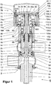
- a seat cleaning double seat valve 1 of the second valve type in conjunction with a drive 70 according to the invention is in its closed position in FIG. 1 shown. It has two serially arranged, relatively movable, each designed as a seat plate closing members 3, 4, which in the closed position of the double seat valve 1, the overflow of fluids from a valve housing part 2a, 2b of a valve housing 2 in the other 2b, 2a through these valve housing parts 2a, 2b interconnect connecting opening 2c prevent and limit both in the closed and in an open position, a leakage cavity 5, which is connected to the environment of the double seat valve 1.
- the connection of the leakage cavity 5 with the environment via at least a connection opening 3d in the first closing member 3, which opens into a drain hole 3c of a pipe shaft 3b arranged on the first closing member 3.
- the first closing element 3 In the closed position, the first closing element 3 cooperates via a first seat seal 10 with a first seat surface 2d.1, which is provided in the connecting opening 2c connecting the valve housing parts 2a, 2b with one another.
- the connection opening 2c can be formed directly in the first and / or in the second valve housing part 2a, 2b or indirectly in a seat ring 8, which is embedded in the valve housing parts 2a and / or 2b in a positive and / or cohesive manner.
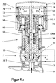
- the first closing member 3 comes sealingly against the second closing member 4 and also transfers the latter during the further opening movement into an open position which ends at the end of the opening operation in a full open position H ( FIG. 1a ).
- the second closing member 4 cooperates with a second seat surface 2e via a second seat seal 11, and a center seal 12 arranged in the end face of the second closing member 4 facing the first closing member 3 ensures in each partial open position of both closing members 3, 4 and up for full open position H for a seal of the closing members 3, 4 against each other and thus also for a secure sealing of the leakage cavity 5 with respect to the interiors of the interconnected valve housing parts 2a, 2b.
- the tubular shaft 3b can, as exemplified, be formed as a first pressure equalizing piston and is led out via a housing ring 17 in the first valve housing part 2a sealed in the environment, the seal relative to the first valve housing part 2a by means of a first rod seal 13 and the guide in the housing ring 17th done by means of a guide ring, not shown.
- the dimensioning of the tubular shaft 3 b in the form of a first pressure equalizing piston generally takes place in such a way that its outer diameter approximately corresponds to the outer diameter of the cross section enclosed by the first seat seal 11.
- the connection of the housing ring 17 with the first valve housing part 2a by means of a clamping ring. 9
- the first closing member 3 is connected to a first adjusting rod 3a and the second closing member 4 is connected to a latter concentrically enclosing, designed as a hollow rod and preferably in the form of a second pressure equalizing piston second adjusting rod 4a.
- the dimensioning of the second pressure compensation piston takes place according to the same criteria, according to which the first is designed, ie that the outer diameter of the second pressure equalizing piston approximately corresponds to the outer diameter of the enclosed by the second seat seal 11 cross-section.
- the adjusting rods 3a, 4a are on one side out of the second valve housing part 2b and out on the way via a subsequent lantern housing 6 in the drive 70 according to the invention.
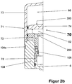
- the lantern housing 6 is fixedly connected at its end facing away from the second valve housing part 2b with a housing bottom 72 of the drive 70, preferably positive and non-positive, for example by screwing ( FIG. 2b ).
- the first adjusting rod 3a is fixedly connected in the axial extension region of the lamp housing 6 to a piston rod 76, the latter penetrating the housing bottom 72 indirectly sealed and engaging at its other end in a fixed connection to a first drive piston 74.
- the fixed connection between the lamp housing 6 and the second valve housing part 2b for example, produces a further clamping ring 9.
- the second adjusting rod 4a finds its displaceable adhesive at its point of penetration in the second valve housing part 2b in a second rod seal 14 arranged there, it passes through an unspecified seal slidably sealed the drive-side end of the lamp housing 6 and ends in the drive 70th
- the outside of a housing 71 FIGS. 1a . 1
- the first drive piston 74 and the end of the housing bottom 72 facing it form between them a first pressure medium space 82 which can be acted upon by a first pressure means D1 and which is bounded radially on the outside by a housing cover part 73.
- the first drive piston 74, the housing bottom 72 and the jacket region of the housing cover part 73 form, with the circumscribed first pressure medium chamber 82, a main adjustment device 200 for producing the full open position H.
- the opening movement of the Double seat valve 1 is introduced from the illustrated closed position and the full open position H is reached when the first pressure medium chamber 82, the first pressure medium D1 is supplied via a not shown and designated way.
- the housing cover part 73 also spans space-forming the first drive piston 74, the latter being simultaneously performed sealed radially outside in the housing cover part 73, and between the first drive piston 74 and the housing cover part 73, a fourth pressure medium chamber 88 is formed ( FIG. 1 ).
- the first drive piston 74 facing the end of the housing bottom 72 passes radially inwardly and in the direction of the lamp housing 6 in a preferably screwed solid sleeve 90 which is so positively enclosed at its other, free end of a movable sleeve 94 that the movable sleeve 94th is axially displaceable over the entire length of the fixed sleeve 90, but at the free end of the fixed sleeve 90 and in the direction of the lamp housing 6 but comes to rest on the fixed sleeve 90.
- the fixed sleeve 90 remote from the end of the movable sleeve 94 serves a first spring 96, preferably a coil spring, as a support, wherein the first spring 96 on the other hand in the radially inner region of the housing bottom 72 is supported.
- the housing bottom 72, the fixed sleeve 90 and the movable sleeve 94 thus form a so-called.
- Spring cage for the first spring 96 which biases the latter in the stop position of the movable sleeve 94 on the fixed sleeve 90 by a defined amount. In intermediate positions, the tension of the first spring 96 against the vorg. Preload increased accordingly.
- the solid sleeve 90 facing away from the end of the movable sleeve 94 is supported on a spring abutment 100a disposed on the first adjusting rod 3a, so that the first spring 96, the first adjusting rod 3a and thus the first closing member 3 always in the direction of the first seat 2d .1 acted upon by their respective biasing force.
- a control unit 104 is arranged according to the invention in the axial extension region of the drive 70, which forms a radially outer side part thereof.
- This control unit 104 is preferably positioned within the largest radial dimension of the drive 70, this dimension being determined solely by the drive-specific components, i. the kinematics mechanically defining components generated.
- this largest radial dimension determined from the outer diameter of the housing 71, which is usually determined by the diameter of the housing cover part 73, in which the first drive piston 74 is guided directly axially displaceable and sealed.
- the outer diameter of the control unit 104 is preferably dimensioned so that the control unit 104 and the housing cover part 73 radially merge into one another on the outside and together form the housing 71.
- the control unit 104 is preferably designed to be annular and self-contained, and is preferably connected to the housing bottom 72 in a positive and non-positive manner by means of fastening means 106 (FIG. FIG. 2b ), such as screws, firmly connected. From the FIGS. 1 and 2 B It can be seen that the control unit 104 is firmly connected to the housing base 72 on the one hand under the above-described radial dimensional conditions and, on the other hand, surrounds the end of the lantern housing 6 facing away from the valve housing 2.
- a hollow rod 74a and a rod 74b are fixed in a diametrical arrangement, on the other hand pass through the housing bottom 72 slidably and sealed and then in a first blind hole 104c (hollow rod 74a) and a second blind hole 104d (Rod 74b) engage in the annular control unit 104 with radial play.
- the hollow rod 74a engages completely through the first drive piston 74, so that a fourth pressure medium D4, (D4) can be supplied to the fourth pressure medium chamber 88 via an inner channel 74a.1 formed inside the hollow rod 74a.
- a related supply of fourth pressure medium (D4) is required when in the double seat valve 1 of the second valve type designed as a seat plate first closing member 3 is to be pressed in its closed position with an additional force Z in addition to acting in the closed position biasing force of the first spring 96 on the first seat 2d.1 ( Figure 1c ).
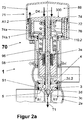
- the supply of fourth pressure means D4 serves to generate a first partial stroke T1 of the first closing member 3 (FIG. FIG. 2a ).
- the rod 74b is intended, with its end remote from the first drive piston 74, to image its respective position between the closed and full open positions H.
- At least one first means for position detection or displacement measurement 110.1 may be positioned in the control unit 104 such that this first means 110.1 provides position reports from the end of the rod 74b.
- the control unit 104 can normally accommodate at least a first pilot valve 108.1 for controlling a pressure medium D, unless an external control is provided for this purpose. With regard to a related arrangement is on the Figures 3 and 4 and the associated description.
- the control unit 104 can also have at least one indicator light 104a radially on the outside, so that it is easily visible to a viewer ( FIGS.
- annular second drive piston 78 is arranged, which is radially outwardly and inwardly guided in the housing bottom 72 axially displaceable and sealed, so that between the housing bottom 72 and the second drive piston 78, a second pressure medium chamber 84 is formed is.
- the second drive piston 78 has a limited axial stroke, since it on the one hand on the stationary housing bottom 72 and on the other hand on a stop portion 90a of the fixed sleeve 90, which acts as a first stop A1.1 comes to rest. In the context of this limited stroke can, starting from the closed position of the double seat valve 1, the first drive piston 74 upon application of the second pressure medium chamber 84 with a second pressure medium D2 (s. FIG.
- first closing member 3 On the presentation position, are shifted upwards by the first partial stroke T1.
- the first partial stroke T1 itself results, after the second drive piston 78 has come into a driving connection with the first drive piston 74, from the then existing axial distance between the relevant upper edge of the second drive piston 78 and the associated first stop A1.1.
- the first closing element 3 With the first partial stroke T1, the first closing element 3 is converted into a first partial open position T1, a first seat cleaning position, in which a first annular gap S1 acting as a throttle gap is formed between an unspecified leakage-chamber-side cylindrical extension on the first closing element 3 and the connection opening 2c ( FIG.
- the second drive piston 78 and the housing bottom 72 form, together with the circumscribed second pressure medium chamber 84, a first individual adjustment device 300 for generating the first partially open position T1.
- the first partial open position T1 is taken from the in FIG. 1 apparent closed position and finally achieved when the second pressure medium chamber 84, the second pressure means D2 is supplied via a not shown and designated way ( FIG. 1b ).
- a ring-shaped third drive piston 80 is arranged ( FIG. 1 ), which is radially outwardly in the lantern housing 6 and radially inside on the formed as a hollow rod second adjusting rod 4a each guided axially displaceable and sealed, so that between the lamp housing 6 and the third drive piston 80, a third pressure medium chamber 86 is formed (see also Figure 1c ).
- the third drive piston 80 has a limited axial stroke, since on the one hand on the stationary lamp housing 6 and on the other hand at an unnamed radial return of the stationary housing bottom 72 firmly connected control unit 104 comes to rest, the radial return acts as a third stop A2 (s , FIGS. 1 and 1c ).
- a recess section 4b is formed which, based on the display position and in the closed position of the double-seat valve 1, ends with its lower edge by a defined axial distance below the third stop A2.
- the second closing member 4 is transferred to a second partially open position T2, a second seat cleaning position, in which a second annular gap S2 acting as a throttle gap is formed between an unspecified leakage-chamber-side cylindrical extension on the second closing member 4 and the connection opening 2c a second seat cleaning flow R2 from the second valve housing part 2b via the exposed second seat 2e in the leakage cavity 5 and from there via the connection openings 3d and the drain hole 3c in the vicinity of the double seat valve 1 can ( Figure 1c ).
- the third drive piston 80 and the lamp housing 6 form with the circumscribed third pressure medium chamber 86, which is acted upon by the third pressure means D3, a second Einzelverstell sensible 400 for generating the second partially open position T2.
- the second partial release T2 is taken from the in FIG. 1 apparent closing position initiated and finally achieved when the third pressure medium chamber 86, the third pressure means D3 is supplied via a not shown and designated way ( Figure 1c ).
- the spring abutment 100a and a spring abutment recess 100b formed thereon engages, based on the presentation position, from below a spring housing 102 slidably, which is prevented from sliding down.
- the spring housing 102 receives a second spring 98, which is supported on the underside of the spring housing 102 and the top of the spring abutment 100a.
- the first spring 96 is, as already described above, under bias between the housing bottom 72 above and the lower end of the movable sleeve 94 on the other.
- the first closing member 3 is pressed by means of the bias generated in this closed position in the first spring 96 to its associated first seat 2d.1.
- the power flow from the first spring 96 via the lower end of the movable sleeve 94 to the spring abutment 100a and from there to the first adjusting rod 3a and thus the first closing member 3.
- the second spring 98 is also under a defined bias, the second closing member 4 also presses on its associated second seat 2e.
- the first, independently driven closing member 3 is raised against the biasing force of the first spring 96 of its associated first seat 2d.1 and it, as soon as the pickup position of the second closing member 4 completed by the first closing member 3 and the center seal 12 between the two for engagement arrived, both closing members 3, 4 compressed only by the then generated by the second spring 98 biasing force and sealed against each other.
- pilot valves 108.1, 108.2 and 108.3 are required, which in the control unit 104 according to the invention, as in FIGS Figures 3 and 4 shown, easily together can be arranged with the necessary, but not shown ways to the respective guidance and distribution of the pressure medium D, D1 to D4, (D4).
- this does not apply if the control of the pressure medium via an external control unit and the supply of the same take place in the associated pressure medium spaces from the vicinity of the double seat valve.
- More than one means for position detection or displacement measurement namely the first means 110.1 for the closing and full open position H of the first closing member 3 (FIG. FIGS. 1 .
- the position detection or distance measurement on the second closing member 4 is not carried out indirectly on the way the position detection on the first closing member 3 or directly via means which are preferably arranged in the externally accessible area of the lamp housing 6, as in both cases
- Prior art to reduce the design effort so far is the rule, but originary and appropriate to the second closing member 4 firmly connected second adjustment rod 4a or a standing with this solidly connected component, such as the recess section 4b, whose position from the third Means 110.3 can be detected.
- the arrangement of means of a control logic 111 in the control unit 104 is also given without problems.
- a seat-cleanable double-seat valve 1 of the first valve type differs from that of the second valve type in that the first closing member 3 is formed as a spool which, in the closed position of the double-seat valve 1, is formed in a first seating surface 2d formed by the communication opening 2c .2, which is designed as a cylindrical seat, sealingly receiving.
- a seat seal 10 is provided in the spool 3, which cooperates exclusively by radial bias with the first seat 2d.2 (radial seal in sliding engagement).
- the seat and closing member configuration of the second closing member 4 corresponds to that of the double-seat valve 1 of the second valve type.
- This also includes the center seal 12 in the second closing member 4, which ensures in each open position of the two closing members 3, 4 for a secure sealing of the leakage cavity 5 to the interiors of the valve housing 2.
- the drive 70 according to the invention for actuating a double seat valve 1 of the first valve type can also be used without restriction for a double seat valve 1, in which the first closing member 3 is likewise designed as a slide piston, but a middle seal 12 is dispensed with in the second closing member 4.
- the second closing member 4 has now a recess at its end facing the first closing member 3 with a substantially cylindrical, aligned with the cylindrical first seat surface 2d.2 in this modified first valve type for replacing the center seal 12 Circumferential wall, and the recess is dimensioned so as to seal during the opening movement, the end portion and the radial first seat seal 10 of the first closing member 3, before the second closing member 4 opens.
- the prototype of a related double-seat valve 1 is from the EP 0 039 319 B1 known.
- the only change in the inventive drive 70 for the first-valve type double-seat valve 1 (first configuration of the drive 70) over the inventive drive 70 in the second configuration is that the drive 70 must take into account the need for the design of the first closing member 3 as a spool now its first partial open position T1 to achieve the first seat cleaning position by one, based on the presentation position, first partial stroke T1 has to be down ( FIG. 2a ). For this reason, the second drive piston 78 and its stroke upwardly limiting stop portion 90a can be omitted without replacement. By eliminating the second drive piston 78 and the stopper portion 90 a, a degree of freedom of movement of the first drive piston 74 results downward (s. FIG. 2 ).
- This degree of freedom of movement is to be dimensioned so that the required first partial stroke T1 is generated by the now possible downward movement of the first drive piston 74 out of the closed position of the double seat valve 1, namely by acting on the fourth pressure fluid chamber 88 with the fourth pressure medium D4 (first configuration of FIG Drive 70).
- the limitation of the first partial stroke T1 is effected by a second stop A1.2 formed on the housing bottom 72 (FIG. Figures 2 . 2a ).
- the first closing element 3 Due to the first partial lift T1, which is now directed downwards, the first closing element 3 is transferred to the first partial open position T1, the first seat cleaning position, between an unmarked leakage-chamber-side cylindrical extension on the first closing element 3 and the cylindrical first seating surface 2d.2 in the connection opening 2c of the first annular gap S1 acting as a throttle gap, via which the first seat cleaning flow R1 from the first valve housing part 2a via the exposed first seat 2d.2 in the leakage cavity 5 and from there via the connection openings 3d and the drain hole 3c in the vicinity of the double seat valve 1 can get.
- the completion of the first partial stroke T1 is reported via second means 110.2.
- the first drive piston 74 and the housing cover part 73 form with the bounded fourth pressure medium chamber 88 in the first configuration of the drive 70 according to the invention and thus for a double seat valve 1 of the first valve type, the first individual adjustment device 300 for generating the first partial open position T1.
- the first partial open position T1 is taken from the in FIG. 2 apparent closed position initiated and finally achieved when the fourth pressure fluid chamber 88 the fourth pressure means D4 via the inner channel 74a.1 and a feeding, not shown and designated path is supplied ( FIG. 2a ).
- the axial definition of the valve formed as a slide first closing member 3 in its closed position which can basically take this closed position in any axial position within the cylindrical seat 2d.2, takes place in that the movable sleeve 94 under the bias of the first spring 96 in their is thus located a stop upward for the spring abutment 100a and thus for the first adjusting rod 3a and connected to it first closing member 3, wherein now the spring abutment 100a with the generated in this position by the second spring 98 biasing force against this stop is pressed.
- the second spring 98 finds its other-sided support indirectly via the resting on its second seat 2e second closing member 4 on the way via the spring housing 102, the insert 4c and the second adjusting 4a.
- the Figures 3 and 4 show how the arrangement of the components within the control unit 104 according to the invention in a full equipment for a seat-cleaning double-seat valve 1 can look like.
- the control unit 104 and thus the drive 70 centrally supplied from the outside pressure medium D passes through a Druckmitelan gleich 112 and via a not shown, extending in the axial direction channel into a distribution channel 114 (FIG. FIG. 4 ), from which the pilot valves 108.1, 108.2 and 108.3 are supplied with pressure medium D.
- the first pilot valve 108.1 which effects the full opening stroke H, controls and supplies a non-designated channel with the first pressure medium D1, which enters the first pressure medium chamber 82 ( FIGS. 1a . 2 ).
- the second pilot valve 108.2 which generates the first partial open position T1 for the double-seat valve 1 of the second valve type, controls and acts on a non-designated channel with the second pressure medium D2, which exits into the second pressure medium chamber 84 ( Figures 3 . 4 and 1b ).
- the first partial stroke T1 is effected by the fourth pressure means D4 which, via the inner channel 74a.1 extending in the hollow rod 74a, into the fourth pressure medium chamber 88 above the first drive piston 74 passes ( FIGS. 4 . 3 ).
- the third partial valve T2 generating third pilot valve 108.3 controls and acts on a non-designated channel with the third pressure medium D3, which exits into the third pressure medium chamber 86 ( Figures 3 . 1c ).
- the second pilot valve 108.2 in conjunction with the NOT element 116 controls the inner channel 74a.1 of the hollow rod 74a, so that the fourth pressure medium chamber 88 with the fourth pressure means (D4) (Note: () stands for additional force by D4) is acted upon ( FIGS. 1 . 1c ).
- control unit 104 provides space for the means of the control logic 111 (FIG. FIG. 3 ).
- the position of the first closing member 3 is imaged via the rod 74b in the control unit 104.
- First means 110.1 fastened to a rod which is not marked indicate the closing and the full open position H.
- Second means 110.2 fastened to a further rod not designated report the completion of the first partial stroke or first partial opening T1 (first closing member 3).
- the execution of the second partial lift or the second partial open position T2 (second closing element 4) is reported by third means 110.3, which detect the position of the recess section 4b, which depicts the respective position of the second closing element 4.
- Means 110.1 to 110.3 may be non-contact sensors that register the change of a magnetic field, the respective magnetic field being generated by at least one permanent magnet fixed to the rod 74b or the recess portion 4b.
- control unit 104 may be enveloped by a jacket 104b, which is made metallic, for example.
- the indicator lights 104a in various embodiments described above, for example, either visible behind transparent windows in the shell 104b or they are integrated at least with their outer boundary in the shell 104b.
- the drive 70 according to the invention is also suitable for a double seat valve of the first or the second type of valve, in which in each case the two seat cleaning positions (first and second partial open position T1, T2) are not required or desired.
- all components, especially the second and the third drive piston 78, 80 and the means for controlling and acting on the drive piston 78, 80 associated pressure medium spaces with pressure medium, which make the operability of the first and second Einzelverstell responded 300, 400, if these components in the context of the main adjustment 200 or the generation of an additional force Z to support the first spring 96 are not mandatory.
- Both the drive 70 and the control unit 104 each represent an independent inventive solution.
- the drive 70 according to the invention can also be implemented without the control unit 104 according to the invention, as far as the latter is concerned with the internal configuration in the manner described above with first and second control means in the periphery of claim 8 goes.
- the control unit 104 as far as their placement according to the invention is concerned, can be arranged on any drive for double-seat valves, if this is adapted accordingly.
- the drive 70 according to the invention alone, ie without the above-described control unit 104 with its internal features within the scope of claim 8, can also be provided in a conventional manner with a on the valve housing 2 remote from the drive 70 arranged control unit, as shown in the Described in the introduction to the introduction of the prior art. In this case, with a view to a position detection of the first adjusting rod 3a, this indirectly extends beyond the piston rod 76 and displaceably guided through the head region of the housing cover part 73. The pressure medium spaces are then connected in a conventional manner to associated paths for the respective pressure medium.
Landscapes
- Engineering & Computer Science (AREA)
- General Engineering & Computer Science (AREA)
- Mechanical Engineering (AREA)
- Fluid-Driven Valves (AREA)
- Mechanically-Actuated Valves (AREA)
Priority Applications (1)
| Application Number | Priority Date | Filing Date | Title |
|---|---|---|---|
| PL12812835T PL2976558T3 (pl) | 2011-12-03 | 2012-11-28 | Zawór dwugniazdowy z napędem |
Applications Claiming Priority (2)
| Application Number | Priority Date | Filing Date | Title |
|---|---|---|---|
| DE201110120287 DE102011120287B3 (de) | 2011-12-03 | 2011-12-03 | Antrieb zum Schalten eines Doppelsitzventils |
| PCT/EP2012/004899 WO2013079190A1 (de) | 2011-12-03 | 2012-11-28 | Antrieb zum schalten eines doppelsitzventils |
Publications (2)
| Publication Number | Publication Date |
|---|---|
| EP2976558A1 EP2976558A1 (de) | 2016-01-27 |
| EP2976558B1 true EP2976558B1 (de) | 2019-02-27 |
Family
ID=47070768
Family Applications (1)
| Application Number | Title | Priority Date | Filing Date |
|---|---|---|---|
| EP12812835.2A Active EP2976558B1 (de) | 2011-12-03 | 2012-11-28 | Doppelsitzventil mit antrieb |
Country Status (6)
| Country | Link |
|---|---|
| US (1) | US9423035B2 (pl) |
| EP (1) | EP2976558B1 (pl) |
| CN (1) | CN104364568B (pl) |
| DE (1) | DE102011120287B3 (pl) |
| PL (1) | PL2976558T3 (pl) |
| WO (1) | WO2013079190A1 (pl) |
Cited By (1)
| Publication number | Priority date | Publication date | Assignee | Title |
|---|---|---|---|---|
| DE102022112275A1 (de) | 2022-05-17 | 2023-11-23 | Technische Universität Dresden, Körperschaft des öffentlichen Rechts | Vorsteuerbares hydraulisches Sitzventil und Anordnung zur Spülung eines hydraulischen Ventils |
Families Citing this family (10)
| Publication number | Priority date | Publication date | Assignee | Title |
|---|---|---|---|---|
| CN103672021B (zh) * | 2013-12-02 | 2017-04-26 | 东正科技有限公司 | 一种可自清洗及杀菌式双座阀 |
| DK178687B1 (en) * | 2015-11-09 | 2016-11-14 | Kmatic Aps | Multifunctional Sanitary Valve and Method of Operating Such |
| DE202017103194U1 (de) | 2017-05-26 | 2018-08-28 | Neoperl Gmbh | Sanitärventil |
| CN108266538B (zh) * | 2018-02-14 | 2024-02-09 | 珠海宝银智能科技有限公司 | 一种液化气瓶复合双自截止阀门及物联网控制系统 |
| JP6902789B2 (ja) * | 2018-02-20 | 2021-07-14 | 株式会社不二工機 | 電動弁 |
| DE102018104148B4 (de) * | 2018-02-23 | 2023-06-15 | Straub Kg | Stellantrieb für ein Ventil sowie Anordnung mit demselben |
| KR20220040475A (ko) * | 2019-07-29 | 2022-03-30 | 아벤틱스 코포레이션 | 이중 밸브 부재 작동에 적합한 클러치를 구비한 밸브 어셈블리 |
| EP4176187A1 (de) * | 2020-07-02 | 2023-05-10 | GEA Tuchenhagen GmbH | Antrieb für ein ventil und verfahren |
| CN117460908A (zh) | 2021-06-11 | 2024-01-26 | 基伊埃图亨哈根有限公司 | 双座阀 |
| EP4105525A1 (en) | 2021-06-15 | 2022-12-21 | Alfa Laval Corporate AB | Valve arrangement, actuator arrangment and methods of detecting a first position therein |
Family Cites Families (17)
| Publication number | Priority date | Publication date | Assignee | Title |
|---|---|---|---|---|
| SE432982B (sv) * | 1980-04-24 | 1984-04-30 | Alfa Laval Ab | Blandningsseker ventil |
| DE3133273C2 (de) * | 1981-08-22 | 1985-10-17 | Otto Tuchenhagen GmbH & Co KG, 2059 Büchen | Reinigbares Doppelsitzventil mit Leckkontrolle |
| DE3501739C1 (de) * | 1985-01-19 | 1986-04-24 | Otto Tuchenhagen GmbH & Co KG, 2059 Büchen | Anordnung zur Steuerung von Druckmittel für einen Antrieb eines Ventils |
| DE4014474C1 (en) * | 1990-05-07 | 1992-01-23 | Apv Rosista Gmbh, 4750 Unna, De | Disc valve control head - is mounted on valve housing via spacer with inspection holes |
| US5165443A (en) * | 1991-09-13 | 1992-11-24 | Itt Corporation | Double block and vent valve system with improved flow handling feature |
| DE29516247U1 (de) * | 1995-10-13 | 1996-01-25 | Kieselmann GmbH, 75438 Knittlingen | Steuerkopf für Armaturen mit pneumatischem Antrieb für die Lebensmittel- und Getränkeindustrie |
| DE19548860C1 (de) | 1995-12-27 | 1997-01-16 | Tetra Laval Holdings & Finance | Absperrventil |
| DE69625344T2 (de) * | 1996-07-15 | 2003-09-18 | Toyo Stainless Steel Industries Co., Ltd. | Doppelsitzventil |
| DE19900239C1 (de) * | 1999-01-07 | 2000-06-21 | Tuchenhagen Gmbh | Antrieb für ein sitzreinigungsfähiges Doppelsitzventil |
| EP1387975B2 (de) * | 2001-05-12 | 2008-09-17 | TUCHENHAGEN GmbH | Verfahren und vorrichtung zur steuerung der schaltbewegung eines ventils |
| DE10234482B3 (de) * | 2002-07-29 | 2004-04-22 | Tuchenhagen Gmbh | Vorrichtung zum Antrieb für Doppelsitzventile |
| DE502005004269D1 (pl) * | 2004-03-15 | 2008-07-10 | Tuchenhagen Gmbh | |
| EP1725794A1 (de) | 2004-03-15 | 2006-11-29 | TUCHENHAGEN GmbH | Vorrichtung zum antrieb eines doppelsitzventils |
| DE102006039493B4 (de) * | 2006-08-21 | 2016-06-30 | Kieselmann Gmbh | Doppelt dichtendes Ventil, insbesondere für Lebensmittel-, Getränke- und die pharmazeutische Industrie |
| DE102008004597B4 (de) * | 2008-01-16 | 2017-06-08 | Gea Tuchenhagen Gmbh | Sitzreinigungsfähiges Doppelsitzventil |
| FR2956181B1 (fr) * | 2010-02-09 | 2012-02-24 | Defontaine | Dispositif de vanne multivoies pour la circulation de fluides |
| DE102010030299A1 (de) * | 2010-06-21 | 2011-12-22 | Krones Aktiengesellschaft | Vorrichtung zum Antreiben eines Doppelsitzventils |
-
2011
- 2011-12-03 DE DE201110120287 patent/DE102011120287B3/de active Active
-
2012
- 2012-11-28 US US14/362,318 patent/US9423035B2/en active Active
- 2012-11-28 CN CN201280066767.3A patent/CN104364568B/zh active Active
- 2012-11-28 PL PL12812835T patent/PL2976558T3/pl unknown
- 2012-11-28 WO PCT/EP2012/004899 patent/WO2013079190A1/de not_active Ceased
- 2012-11-28 EP EP12812835.2A patent/EP2976558B1/de active Active
Non-Patent Citations (1)
| Title |
|---|
| None * |
Cited By (2)
| Publication number | Priority date | Publication date | Assignee | Title |
|---|---|---|---|---|
| DE102022112275A1 (de) | 2022-05-17 | 2023-11-23 | Technische Universität Dresden, Körperschaft des öffentlichen Rechts | Vorsteuerbares hydraulisches Sitzventil und Anordnung zur Spülung eines hydraulischen Ventils |
| DE102022112275B4 (de) | 2022-05-17 | 2024-08-01 | Technische Universität Dresden, Körperschaft des öffentlichen Rechts | Vorsteuerbares hydraulisches Sitzventil und Anordnung zur Spülung eines hydraulischen Ventils |
Also Published As
| Publication number | Publication date |
|---|---|
| CN104364568B (zh) | 2016-11-16 |
| US9423035B2 (en) | 2016-08-23 |
| DE102011120287B3 (de) | 2012-11-15 |
| HK1206807A1 (en) | 2016-01-15 |
| EP2976558A1 (de) | 2016-01-27 |
| WO2013079190A1 (de) | 2013-06-06 |
| PL2976558T3 (pl) | 2019-09-30 |
| US20140311600A1 (en) | 2014-10-23 |
| CN104364568A (zh) | 2015-02-18 |
Similar Documents
| Publication | Publication Date | Title |
|---|---|---|
| EP2976558B1 (de) | Doppelsitzventil mit antrieb | |
| DE102009006445B3 (de) | Proportional-Druckregelventil | |
| DE3717341C2 (pl) | ||
| AT400748B (de) | Patronenventil | |
| DE102013114595B4 (de) | Sicherheitsventil | |
| EP0868619B1 (de) | Vorrichtung zum antrieb für doppelsitzventile | |
| CH655984A5 (de) | Magnetventil mit leistungsverstaerker. | |
| WO2009100921A1 (de) | Vorrichtung zur verbindung eines ventilgehäuses mit einem stellantrieb bei einem als hubventil fungierenden prozessventil | |
| EP1525415B1 (de) | Vorrichtung zum antrieb f r doppelsitzventile | |
| WO1992009836A1 (de) | Einschraubventil | |
| EP2530365B1 (de) | Ventileinsatz für eine Sanitärarmatur | |
| EP0496105B1 (de) | Berührungslos gesteuerte Sanitärarmatur | |
| DE4235929A1 (de) | Zylinderverstellung | |
| WO1993019301A1 (de) | Hydraulische antriebsvorrichtung mit einem zylinder | |
| WO2004023009A1 (de) | Vorrichtung zum antrieb für doppelsitzventile | |
| EP0845602A2 (de) | Elektohydraulische Steuervorrichtung | |
| DE3545393C2 (pl) | ||
| EP2711595A1 (de) | Ventilvorrichtung mit Doppelsitz | |
| EP0657004A1 (de) | Ventileinheit mit einander gegenüberliegenden ventilen. | |
| DE102007025567A1 (de) | Elektropneumatisches Ventil, insbesondere Vorsteuerventil eines pneumatischen Wegeventils | |
| DE102004042190B4 (de) | Kraftstoffinjektor mit zwei von einer Servoventileinheit getrennt steuerbaren Steuerräumen | |
| DE102011113046B4 (de) | Steuereinheit für ein Ventil | |
| DE69715199T2 (de) | Ventilanordnung für Heizsysteme und Wasserheizgeräte und Verfahren zu ihrer Herstellung | |
| EP1729073A1 (de) | Heizkörpersystem mit mehrfacher Anschlussmöglichkeit | |
| EP2778437B1 (de) | Hydraulisches Ventil |
Legal Events
| Date | Code | Title | Description |
|---|---|---|---|
| PUAI | Public reference made under article 153(3) epc to a published international application that has entered the european phase |
Free format text: ORIGINAL CODE: 0009012 |
|
| 17P | Request for examination filed |
Effective date: 20150703 |
|
| AK | Designated contracting states |
Kind code of ref document: A1 Designated state(s): AL AT BE BG CH CY CZ DE DK EE ES FI FR GB GR HR HU IE IS IT LI LT LU LV MC MK MT NL NO PL PT RO RS SE SI SK SM TR |
|
| GRAP | Despatch of communication of intention to grant a patent |
Free format text: ORIGINAL CODE: EPIDOSNIGR1 |
|
| STAA | Information on the status of an ep patent application or granted ep patent |
Free format text: STATUS: GRANT OF PATENT IS INTENDED |
|
| RIC1 | Information provided on ipc code assigned before grant |
Ipc: F16K 31/122 20060101ALI20180801BHEP Ipc: F16K 1/44 20060101AFI20180801BHEP |
|
| INTG | Intention to grant announced |
Effective date: 20180824 |
|
| GRAS | Grant fee paid |
Free format text: ORIGINAL CODE: EPIDOSNIGR3 |
|
| GRAA | (expected) grant |
Free format text: ORIGINAL CODE: 0009210 |
|
| STAA | Information on the status of an ep patent application or granted ep patent |
Free format text: STATUS: THE PATENT HAS BEEN GRANTED |
|
| AK | Designated contracting states |
Kind code of ref document: B1 Designated state(s): AL AT BE BG CH CY CZ DE DK EE ES FI FR GB GR HR HU IE IS IT LI LT LU LV MC MK MT NL NO PL PT RO RS SE SI SK SM TR |
|
| REG | Reference to a national code |
Ref country code: GB Ref legal event code: FG4D Free format text: NOT ENGLISH |
|
| REG | Reference to a national code |
Ref country code: CH Ref legal event code: EP |
|
| REG | Reference to a national code |
Ref country code: DE Ref legal event code: R096 Ref document number: 502012014366 Country of ref document: DE |
|
| REG | Reference to a national code |
Ref country code: AT Ref legal event code: REF Ref document number: 1101840 Country of ref document: AT Kind code of ref document: T Effective date: 20190315 |
|
| REG | Reference to a national code |
Ref country code: IE Ref legal event code: FG4D Free format text: LANGUAGE OF EP DOCUMENT: GERMAN |
|
| REG | Reference to a national code |
Ref country code: NL Ref legal event code: MP Effective date: 20190227 |
|
| REG | Reference to a national code |
Ref country code: LT Ref legal event code: MG4D |
|
| REG | Reference to a national code |
Ref country code: CH Ref legal event code: NV Representative=s name: ISLER AND PEDRAZZINI AG, CH |
|
| PG25 | Lapsed in a contracting state [announced via postgrant information from national office to epo] |
Ref country code: NL Free format text: LAPSE BECAUSE OF FAILURE TO SUBMIT A TRANSLATION OF THE DESCRIPTION OR TO PAY THE FEE WITHIN THE PRESCRIBED TIME-LIMIT Effective date: 20190227 Ref country code: PT Free format text: LAPSE BECAUSE OF FAILURE TO SUBMIT A TRANSLATION OF THE DESCRIPTION OR TO PAY THE FEE WITHIN THE PRESCRIBED TIME-LIMIT Effective date: 20190627 Ref country code: SE Free format text: LAPSE BECAUSE OF FAILURE TO SUBMIT A TRANSLATION OF THE DESCRIPTION OR TO PAY THE FEE WITHIN THE PRESCRIBED TIME-LIMIT Effective date: 20190227 Ref country code: LT Free format text: LAPSE BECAUSE OF FAILURE TO SUBMIT A TRANSLATION OF THE DESCRIPTION OR TO PAY THE FEE WITHIN THE PRESCRIBED TIME-LIMIT Effective date: 20190227 Ref country code: FI Free format text: LAPSE BECAUSE OF FAILURE TO SUBMIT A TRANSLATION OF THE DESCRIPTION OR TO PAY THE FEE WITHIN THE PRESCRIBED TIME-LIMIT Effective date: 20190227 Ref country code: NO Free format text: LAPSE BECAUSE OF FAILURE TO SUBMIT A TRANSLATION OF THE DESCRIPTION OR TO PAY THE FEE WITHIN THE PRESCRIBED TIME-LIMIT Effective date: 20190527 |
|
| PG25 | Lapsed in a contracting state [announced via postgrant information from national office to epo] |
Ref country code: IS Free format text: LAPSE BECAUSE OF FAILURE TO SUBMIT A TRANSLATION OF THE DESCRIPTION OR TO PAY THE FEE WITHIN THE PRESCRIBED TIME-LIMIT Effective date: 20190627 Ref country code: BG Free format text: LAPSE BECAUSE OF FAILURE TO SUBMIT A TRANSLATION OF THE DESCRIPTION OR TO PAY THE FEE WITHIN THE PRESCRIBED TIME-LIMIT Effective date: 20190527 Ref country code: LV Free format text: LAPSE BECAUSE OF FAILURE TO SUBMIT A TRANSLATION OF THE DESCRIPTION OR TO PAY THE FEE WITHIN THE PRESCRIBED TIME-LIMIT Effective date: 20190227 Ref country code: RS Free format text: LAPSE BECAUSE OF FAILURE TO SUBMIT A TRANSLATION OF THE DESCRIPTION OR TO PAY THE FEE WITHIN THE PRESCRIBED TIME-LIMIT Effective date: 20190227 Ref country code: HR Free format text: LAPSE BECAUSE OF FAILURE TO SUBMIT A TRANSLATION OF THE DESCRIPTION OR TO PAY THE FEE WITHIN THE PRESCRIBED TIME-LIMIT Effective date: 20190227 Ref country code: GR Free format text: LAPSE BECAUSE OF FAILURE TO SUBMIT A TRANSLATION OF THE DESCRIPTION OR TO PAY THE FEE WITHIN THE PRESCRIBED TIME-LIMIT Effective date: 20190528 |
|
| PG25 | Lapsed in a contracting state [announced via postgrant information from national office to epo] |
Ref country code: CZ Free format text: LAPSE BECAUSE OF FAILURE TO SUBMIT A TRANSLATION OF THE DESCRIPTION OR TO PAY THE FEE WITHIN THE PRESCRIBED TIME-LIMIT Effective date: 20190227 Ref country code: IT Free format text: LAPSE BECAUSE OF FAILURE TO SUBMIT A TRANSLATION OF THE DESCRIPTION OR TO PAY THE FEE WITHIN THE PRESCRIBED TIME-LIMIT Effective date: 20190227 Ref country code: SK Free format text: LAPSE BECAUSE OF FAILURE TO SUBMIT A TRANSLATION OF THE DESCRIPTION OR TO PAY THE FEE WITHIN THE PRESCRIBED TIME-LIMIT Effective date: 20190227 Ref country code: AL Free format text: LAPSE BECAUSE OF FAILURE TO SUBMIT A TRANSLATION OF THE DESCRIPTION OR TO PAY THE FEE WITHIN THE PRESCRIBED TIME-LIMIT Effective date: 20190227 Ref country code: DK Free format text: LAPSE BECAUSE OF FAILURE TO SUBMIT A TRANSLATION OF THE DESCRIPTION OR TO PAY THE FEE WITHIN THE PRESCRIBED TIME-LIMIT Effective date: 20190227 Ref country code: EE Free format text: LAPSE BECAUSE OF FAILURE TO SUBMIT A TRANSLATION OF THE DESCRIPTION OR TO PAY THE FEE WITHIN THE PRESCRIBED TIME-LIMIT Effective date: 20190227 Ref country code: ES Free format text: LAPSE BECAUSE OF FAILURE TO SUBMIT A TRANSLATION OF THE DESCRIPTION OR TO PAY THE FEE WITHIN THE PRESCRIBED TIME-LIMIT Effective date: 20190227 Ref country code: RO Free format text: LAPSE BECAUSE OF FAILURE TO SUBMIT A TRANSLATION OF THE DESCRIPTION OR TO PAY THE FEE WITHIN THE PRESCRIBED TIME-LIMIT Effective date: 20190227 |
|
| REG | Reference to a national code |
Ref country code: DE Ref legal event code: R097 Ref document number: 502012014366 Country of ref document: DE |
|
| PG25 | Lapsed in a contracting state [announced via postgrant information from national office to epo] |
Ref country code: SM Free format text: LAPSE BECAUSE OF FAILURE TO SUBMIT A TRANSLATION OF THE DESCRIPTION OR TO PAY THE FEE WITHIN THE PRESCRIBED TIME-LIMIT Effective date: 20190227 |
|
| PLBE | No opposition filed within time limit |
Free format text: ORIGINAL CODE: 0009261 |
|
| STAA | Information on the status of an ep patent application or granted ep patent |
Free format text: STATUS: NO OPPOSITION FILED WITHIN TIME LIMIT |
|
| 26N | No opposition filed |
Effective date: 20191128 |
|
| PG25 | Lapsed in a contracting state [announced via postgrant information from national office to epo] |
Ref country code: SI Free format text: LAPSE BECAUSE OF FAILURE TO SUBMIT A TRANSLATION OF THE DESCRIPTION OR TO PAY THE FEE WITHIN THE PRESCRIBED TIME-LIMIT Effective date: 20190227 |
|
| PG25 | Lapsed in a contracting state [announced via postgrant information from national office to epo] |
Ref country code: TR Free format text: LAPSE BECAUSE OF FAILURE TO SUBMIT A TRANSLATION OF THE DESCRIPTION OR TO PAY THE FEE WITHIN THE PRESCRIBED TIME-LIMIT Effective date: 20190227 |
|
| PG25 | Lapsed in a contracting state [announced via postgrant information from national office to epo] |
Ref country code: LU Free format text: LAPSE BECAUSE OF NON-PAYMENT OF DUE FEES Effective date: 20191128 Ref country code: MC Free format text: LAPSE BECAUSE OF FAILURE TO SUBMIT A TRANSLATION OF THE DESCRIPTION OR TO PAY THE FEE WITHIN THE PRESCRIBED TIME-LIMIT Effective date: 20190227 |
|
| REG | Reference to a national code |
Ref country code: BE Ref legal event code: MM Effective date: 20191130 |
|
| PG25 | Lapsed in a contracting state [announced via postgrant information from national office to epo] |
Ref country code: IE Free format text: LAPSE BECAUSE OF NON-PAYMENT OF DUE FEES Effective date: 20191128 |
|
| PG25 | Lapsed in a contracting state [announced via postgrant information from national office to epo] |
Ref country code: BE Free format text: LAPSE BECAUSE OF NON-PAYMENT OF DUE FEES Effective date: 20191130 |
|
| REG | Reference to a national code |
Ref country code: AT Ref legal event code: MM01 Ref document number: 1101840 Country of ref document: AT Kind code of ref document: T Effective date: 20191128 |
|
| PG25 | Lapsed in a contracting state [announced via postgrant information from national office to epo] |
Ref country code: AT Free format text: LAPSE BECAUSE OF NON-PAYMENT OF DUE FEES Effective date: 20191128 |
|
| PG25 | Lapsed in a contracting state [announced via postgrant information from national office to epo] |
Ref country code: CY Free format text: LAPSE BECAUSE OF FAILURE TO SUBMIT A TRANSLATION OF THE DESCRIPTION OR TO PAY THE FEE WITHIN THE PRESCRIBED TIME-LIMIT Effective date: 20190227 |
|
| PG25 | Lapsed in a contracting state [announced via postgrant information from national office to epo] |
Ref country code: MT Free format text: LAPSE BECAUSE OF FAILURE TO SUBMIT A TRANSLATION OF THE DESCRIPTION OR TO PAY THE FEE WITHIN THE PRESCRIBED TIME-LIMIT Effective date: 20190227 Ref country code: HU Free format text: LAPSE BECAUSE OF FAILURE TO SUBMIT A TRANSLATION OF THE DESCRIPTION OR TO PAY THE FEE WITHIN THE PRESCRIBED TIME-LIMIT; INVALID AB INITIO Effective date: 20121128 |
|
| PG25 | Lapsed in a contracting state [announced via postgrant information from national office to epo] |
Ref country code: MK Free format text: LAPSE BECAUSE OF FAILURE TO SUBMIT A TRANSLATION OF THE DESCRIPTION OR TO PAY THE FEE WITHIN THE PRESCRIBED TIME-LIMIT Effective date: 20190227 |
|
| P01 | Opt-out of the competence of the unified patent court (upc) registered |
Effective date: 20230601 |
|
| REG | Reference to a national code |
Ref country code: CH Ref legal event code: U11 Free format text: ST27 STATUS EVENT CODE: U-0-0-U10-U11 (AS PROVIDED BY THE NATIONAL OFFICE) Effective date: 20251201 |
|
| PGFP | Annual fee paid to national office [announced via postgrant information from national office to epo] |
Ref country code: GB Payment date: 20251120 Year of fee payment: 14 |
|
| PGFP | Annual fee paid to national office [announced via postgrant information from national office to epo] |
Ref country code: FR Payment date: 20251120 Year of fee payment: 14 |
|
| PGFP | Annual fee paid to national office [announced via postgrant information from national office to epo] |
Ref country code: CH Payment date: 20251201 Year of fee payment: 14 |
|
| PGFP | Annual fee paid to national office [announced via postgrant information from national office to epo] |
Ref country code: PL Payment date: 20251112 Year of fee payment: 14 |
|
| PGFP | Annual fee paid to national office [announced via postgrant information from national office to epo] |
Ref country code: DE Payment date: 20260113 Year of fee payment: 14 |