EP2977135A1 - Dispositif et procédé d'établissement d'une empreinte dans un matériau isolant - Google Patents
Dispositif et procédé d'établissement d'une empreinte dans un matériau isolant Download PDFInfo
- Publication number
- EP2977135A1 EP2977135A1 EP14178126.0A EP14178126A EP2977135A1 EP 2977135 A1 EP2977135 A1 EP 2977135A1 EP 14178126 A EP14178126 A EP 14178126A EP 2977135 A1 EP2977135 A1 EP 2977135A1
- Authority
- EP
- European Patent Office
- Prior art keywords
- flux
- insulating material
- drive train
- recess
- melting
- Prior art date
- Legal status (The legal status is an assumption and is not a legal conclusion. Google has not performed a legal analysis and makes no representation as to the accuracy of the status listed.)
- Granted
Links
Images

Classifications
-
- B—PERFORMING OPERATIONS; TRANSPORTING
- B23—MACHINE TOOLS; METAL-WORKING NOT OTHERWISE PROVIDED FOR
- B23D—PLANING; SLOTTING; SHEARING; BROACHING; SAWING; FILING; SCRAPING; LIKE OPERATIONS FOR WORKING METAL BY REMOVING MATERIAL, NOT OTHERWISE PROVIDED FOR
- B23D45/00—Sawing machines or sawing devices with circular saw blades or with friction saw discs
- B23D45/26—Sawing machines or sawing devices with circular saw blades or with friction saw discs with high-speed cutting discs, performing the cut by frictional heat melting the material
-
- B—PERFORMING OPERATIONS; TRANSPORTING
- B23—MACHINE TOOLS; METAL-WORKING NOT OTHERWISE PROVIDED FOR
- B23B—TURNING; BORING
- B23B51/00—Tools for drilling machines
- B23B51/04—Drills for trepanning
-
- B—PERFORMING OPERATIONS; TRANSPORTING
- B23—MACHINE TOOLS; METAL-WORKING NOT OTHERWISE PROVIDED FOR
- B23B—TURNING; BORING
- B23B51/00—Tools for drilling machines
- B23B51/08—Drills combined with tool parts or tools for performing additional working
-
- B—PERFORMING OPERATIONS; TRANSPORTING
- B26—HAND CUTTING TOOLS; CUTTING; SEVERING
- B26D—CUTTING; DETAILS COMMON TO MACHINES FOR PERFORATING, PUNCHING, CUTTING-OUT, STAMPING-OUT OR SEVERING
- B26D3/00—Cutting work characterised by the nature of the cut made; Apparatus therefor
- B26D3/006—Cutting work characterised by the nature of the cut made; Apparatus therefor specially adapted for cutting blocs of plastic material
-
- B—PERFORMING OPERATIONS; TRANSPORTING
- B26—HAND CUTTING TOOLS; CUTTING; SEVERING
- B26F—PERFORATING; PUNCHING; CUTTING-OUT; STAMPING-OUT; SEVERING BY MEANS OTHER THAN CUTTING
- B26F3/00—Severing by means other than cutting; Apparatus therefor
- B26F3/06—Severing by using heat
- B26F3/08—Severing by using heat with heated members
-
- B—PERFORMING OPERATIONS; TRANSPORTING
- B26—HAND CUTTING TOOLS; CUTTING; SEVERING
- B26F—PERFORATING; PUNCHING; CUTTING-OUT; STAMPING-OUT; SEVERING BY MEANS OTHER THAN CUTTING
- B26F1/00—Perforating; Punching; Cutting-out; Stamping-out; Apparatus therefor
- B26F1/16—Perforating by tool or tools of the drill type
-
- E—FIXED CONSTRUCTIONS
- E04—BUILDING
- E04B—GENERAL BUILDING CONSTRUCTIONS; WALLS, e.g. PARTITIONS; ROOFS; FLOORS; CEILINGS; INSULATION OR OTHER PROTECTION OF BUILDINGS
- E04B1/00—Constructions in general; Structures which are not restricted either to walls, e.g. partitions, or floors or ceilings or roofs
- E04B1/62—Insulation or other protection; Elements or use of specified material therefor
- E04B1/74—Heat, sound or noise insulation, absorption, or reflection; Other building methods affording favourable thermal or acoustical conditions, e.g. accumulating of heat within walls
- E04B1/76—Heat, sound or noise insulation, absorption, or reflection; Other building methods affording favourable thermal or acoustical conditions, e.g. accumulating of heat within walls specifically with respect to heat only
- E04B1/762—Exterior insulation of exterior walls
- E04B1/7629—Details of the mechanical connection of the insulation to the wall
- E04B1/7633—Dowels with enlarged insulation retaining head
Definitions
- the present invention relates to a device for creating a recess in insulating materials, as well as a corresponding method.
- Insulation holders are often used for fixing insulating materials. Such insulation holders often have a dowel shaft and a dowel plate arranged thereon. After assembly, the anchor plate is either on the surface of the insulation or in a recess in the insulation. For mounting the insulation holder in a recess, a hole is first created by the insulation material in a substrate and then created with a special installation tool in the insulation a recess.
- EP 2 042 666 A2 describes an assembly tool having a milling device at the bottom with which the recess can be milled into the insulating material.
- the object of the present invention is therefore to provide a device for creating a recess in an insulating material and a corresponding method, with which the disadvantages in the prior art can be conveniently and easily resolved.
- the inventive device for creating a recess in an insulating material has a drive train, wherein the drive train is adapted in a first end region for connection to a drive tool.
- the device also comprises a melting means for melting the recess, wherein the melting means is arranged on the drive train and extends substantially perpendicular to the drive train and the recess preferably melts by means of contact friction in the insulating material. Therefore, the flux is preferably a friction agent.
- the flux according to the invention makes it possible to create an indentation in the insulating surface, without dissolving insulation particles which could escape into the environment, whereby the softening of the insulating material by means of the introduction of a thermal energy is understood.
- the depressions formed by the device according to the invention by the melting on straight edges. These depressions can be very deep compared to the prior art, since when melting in contrast to compressing or milling does not pay attention to where the insulation from the depression is transported. By merging the insulating material at the edge region of the depression, the structural integrity of the depression is not affected, as would otherwise be the case when dissolving insulation particles.
- the first end region of the drive train is adapted to be connected to a drive tool, for example a drill.
- a drive tool for example a drill.
- This is preferably a non-rotatable connection, i. With the help of the drive tool, a rotational movement can be transmitted to the drive train.
- the connection can be made, for example, by clamping the first end region of the drive train into a corresponding drill chuck of the drive tool. It may also be a one-piece compound, i. the drive train may be part of the drive tool.
- the flux is arranged directly or indirectly on the drive train, wherein in a direct arrangement, the flux is disposed directly, ie without further components on the drive train and wherein in an indirect arrangement, the flux is arranged by means of one or more other components on the drive train. Both arrangements cause a rotational movement of the drive train to be transferred to the flux.
- a transmission may be arranged, for example, a kind of planetary gear, which allows the flux does not rotate uniformly with the drive train but faster or slower.
- a decoupling means is provided between the flux and the drive train, which decouples the rotational movement of the drive train from the rotational movement of the flux. With such a decoupling means, for example, a re-rotation of the flux can be realized if the rotational movement of the drive train has already been stopped.
- the Nachmosen is inertia-dependent in this case.
- the flux or at least one surface of the flux extends substantially perpendicular to the drive train.
- the surface of the flux is substantially parallel to the surface of the insulant when the powertrain is oriented perpendicular to the surface of the insulant.
- a rotational movement of the flux in all directions is possible, so that the flux can be pivoted about a pivot point defined by the ball joint. This allows the recess to be introduced at right angles to the surface of the insulating material, even if the drive tool or the drive train is not held or guided at right angles to the surface.
- the recess is melted by means of contact friction in the insulating material.
- the drive train and the melting means of the device according to the invention can be rotated.
- the surface of the flux comes into contact with the surface of the insulating material.
- a friction arises between the spatially fixed surface of the insulating material and the rotating surface of the flux.
- the side of the flux contacting the insulating material is adapted to process the insulating surface without mechanical abrasion of insulating particles. At least on the insulating material contacting side is no mechanical abrasion, but a melting instead. Even if individual particles dissolve at the contact surface of the flux with the insulating material, they are not dissipated but fused with the remaining insulating material.
- the side of the flux that contacts the insulating material has very little surface roughness for this purpose. This can be achieved for example by a smooth surface on the insulating material contacting side of the flux.
- a small surface roughness of the flux uniform contact with the insulating surface over the entire surface of the contacting side of the flux can be produced.
- the low surface roughness also prevents molten insulating material from adhering to the flux.
- the surface may also have, for example, a special coating which prevents molten insulating material from sticking.
- a kind of Teflon coating can be applied.
- the flux is round.
- the largest possible contact surface for the melting of circular recesses is achieved.
- the flux may have any geometry, for example, the flux may also be triangular or rectangular.
- the flux has a peripheral edge that extends substantially parallel to the drive train.
- the projection is a cutting edge.
- the peripheral edge can also ensure that at the bottom of the recess, a circumferential further recess is produced, which also advantageously position fixing acts on a subsequently introduced pressure plate of a Dämmstoffhalters, which may have a complementary peripheral edge.
- the surface of the flux contacting the insulating material is made of metal.
- metals or metal alloys have a high melting temperature, so that the surface of the flux does not deform even when frictional heat is generated.
- the surface of the flux can also consist of a good heat-conducting and difficult-to-deform plastic material or of a mineral or consist of mixtures of metals, plastics and / or minerals.
- the surface of the flux can also have a coating, so that no molten insulating material adheres to the surface of the flux.
- the device for creating a recess in an insulating material further comprises a stop disc, which is designed to limit a movement of the flux into the insulating material.
- a stop disc which is designed to limit a movement of the flux into the insulating material.
- the circumference of the stop disc is greater than the circumference of the flux.
- the depth of the depression depends, for example, on how far the insulating material contacting side of the flux is removed from the side of the stopper disc contacting the insulating surface.
- the stop disc can be positioned, for example, at several predetermined locations on the drive train, so that different predetermined depths can be achieved. But it is also conceivable that the position of the stop plate along the drive train is arbitrary and can be fixed, for example, with a grub screw. Also, a fixation on the drive train via spring-mounted spherical elements can be done on the stop plate. These elements can engage in corresponding spherical depressions on the drive train and can thus fix the position of the stop plate on the drive train.
- the stop disc and the flux are produced from one part, ie are in one piece. Different depths can be realized in the case of the integral piece of the stop disk and the flux, for example, that the flux and the stop disk are interchangeable as a part and so different flux with different distances between the insulating material contacting side of the flux and the insulating surface contacting side of the Stop disc can be selected.
- the stop disk dissipates more heat due to its greater surface area compared to the surface of the flux, so that the stop disk itself does not act as a flux and does not melt the insulating material.
- This can for example still be supported by the choice of the material of the stop disc, which can be made for example of a poor thermal conductivity material or provided with a coating that reduces the coefficient of friction between the insulating material and stop disk, so that there is only a small heat ,
- the powertrain is in a second end region that is the first end region opposite, adapted for connection to a drill.
- a drill for example, this may be a masonry drill.
- the drive train may for example have a receptacle for the drill.
- the drive train and the drill can also be designed in one piece.
- the device has a centering tip.
- the position of the rotating flux on the surface of the insulating material can thereby be determined and, furthermore, the danger of the melting of the flux can be reduced by an imbalance through the use of the centering.
- the centering tip may be a cylindrical body that tapers toward the surface of the insulating material.
- the centering means may for example be arranged on the drive train or on the flux.
- the flux is releasably attached to the drive train. This attachment can be done for example via a clamping screw on the flux.
- the releasable attachment the flux can be moved along the drive train, for example.
- the flux is replaced by the releasable attachment to another flux.
- a combination of the two alternatives is also possible.
- the flux By moving the flux along the drive train, different thicknesses or deep depressions can be generated by means of a device in insulating materials. This is particularly possible if the device has a drill and / or a stop disc. Replacement of the flux can be helpful, for example, if the diameter of the depression is to be changed or the depth of the depression is to be changed; for this purpose, a melting agent is selected which, for example, has a greater distance from the stopper disc.
- the flux can be designed differently to at different insulating materials to form the well as well as possible.
- the inventive method for creating a recess in an insulating material comprises the following steps on rotating a drive train and a flux disposed thereon, advancing the flux against an insulating material and melting a recess in the insulating material by means of contact friction between the flux and the insulating material.
- the rotating flux which is aligned substantially parallel to the surface of the insulating material, is brought into contact with the surface of the insulating material. Thereafter, by a forward movement of the drive tool, the flux is moved into the insulation, so as to create a depression in the insulation surface.
- the flux melts the recess in the insulating material with an insulating material contacting surface, which is adapted to edit the insulation surface without a mechanical abrasion of insulating particles.
- the flux is moved forward into the insulating material within a projection running around the edge of the flux.
- this projection provides additional stability to prevent slipping, for example, a reciprocating of the flux on the insulating surface.
- the projection is a cutting edge.
- the forward movement of the flux into the insulation material is limited by a stop disk arranged on the device.
- a stop disk arranged on the device.
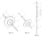
- FIG. 1a shows an exemplary embodiment of the device 1 according to the invention for creating a recess in an insulating material.
- the device 1 consists of a drive train 2 with a first end portion 3 and a second end portion 4.
- the drive train 2 is made of a metal alloy, such as a chromium / titanium alloy or a chromium / vanadium alloy.
- the first end portion 3 of the drive train 2 is configured for connection to a drive tool.
- the drivetrain 2 has notches 5, such as are needed to connect to an SDS, SDS plus, SDS Quick drill chuck of a power drill.
- the first end portion 3 may also have a smooth surface, for connection to a quick-release chuck, or hexagonal to be connected to a known bit receptacle.
- FIG. 1a An exemplary embodiment for a drill bit 6 connected to the second end region 4 is also shown.
- the drill 6 can be rotatably connected to the drive train 2 via a drill chuck attached to the second end region 4 of the drive train 2.
- the embodiment shown also shows a melting agent 7, which is arranged around the circumference of the drive train 2 and is fastened to the drive train 2.
- the flux 7 has a substantially perpendicular to the drive train 2 aligned, closed surface with a low surface roughness, which consists for example of metal.
- the flux 7 consists of a solid or hollow metal body, here for example a cylindrical body, which is arranged around the drive train 2. The size of this cylindrical body determines the size of the depression. The height of the cylinder determines the depth of the recess and the diameter determines the diameter of the recess.
- the flux 7, that is to say the cylindrical body, can also be exchangeable, so that depressions of different sizes can be produced.
- metal the skilled person but also other materials are known which have similar stability and heat conduction properties such as metal, for example, special plastics or minerals or combinations thereof.
- This projection 8 which is a circumferential cutting edge in the example shown, allows further centering of the flux 7 on the insulating material to a pendulum and H e pendulum of the flux 7 on to prevent the insulation surface. Furthermore, this projection 8 allows better heat transfer from the flux 7 in the insulating material, so as to better melt the insulation.
- the in FIG. 1a shown projection 8 has a low surface roughness, to substantially avoid the falling out of insulation chips from the insulation surface.
- the projection 8 could also be a saw-like cutting edge, which mills into the insulating material.
- a stop plate 9 on the insulating material repellent side of the flux 7 is shown.
- This stop disc 9 limits the penetration depth of the flux 7 in the insulation.
- the stop disk 9 has a larger circumference than the circumference of the below-arranged flux 7.
- This stopper plate 9 may for example consist of a poorly thermally conductive plastic, thus reducing the weight and cost of the device 1.
- such a plastic material has the advantage that the stop disc 9 does not penetrate as the flux 7 in the insulating material, since it does not generate enough heat to melt the insulating material.
- the stop disc could also consist of the same material as the flux 7 and continue to be connected by means of a screw with the flux 7 or alternatively be made with the flux 7 in one part.
- FIG. 1b shows an exemplary embodiment of the device 1 according to the invention for creating a recess with a centering tip as a centering.
- a cylindrical, pointed tapered centering be used as a centering.
- the centering tip may be non-rotatably connected to the drivetrain 2 in the same manner as in FIG FIG. 1a shown drill 6.
- the centering tip may be disposed on the flux.
- a centering tip can be selected, for example, if no borehole is to be created through the insulating material into the ground.
- the person skilled in the art is also familiar with further possibilities as to how the centering tip can be fastened.
- Figure 1c shows a side view of the drive train 2 without flux 7.
- the flux 7 can be displaceably arranged along the drive train 2. These are as in Figure 1c shown, along the drive train 2, around the drive train 2 extending around notches 10a-e or recesses mounted at intervals.
- a corresponding tongue which is located on a holder of the retractable flux 7 and which is adapted to engage in the notches 10a-e, the flux 7 can be attached to the drive train 2.
- this tongue can be realized by a clamping screw.
- this allows the use of the device 1 for creating equal deep wells for different thicknesses of insulation.
- the flux 7 may also be connected in another way with the drive train 2, as for example by means of a stepless clamping connection.
- FIGS. 2 show cross-sectional views of an exemplary embodiment of the device 1 according to the invention during the creation of a recess in an insulating material 11th
- the drill 6 arranged on the device 1 is arranged at a substantially right angle to the surface of the insulating material.
- the drill 6 attached to the first end region of the device 1 drills through the insulating material 11 FIG. 2a
- the surface of the flux 7 aligned parallel to the surface of the insulating material 11 is already on the surface Surface of the insulating material 11 on. The rotating movement of the flux 7 produces heat between the two surfaces.
- the substrate 12 for example, a concrete substrate achieved.
- the flux 7 melts a circular depression in the surface of the insulation. As already described above, this can be supported, for example, by means of a projection 8 arranged on the circumference of the flux 7.
- Figure 2c shows the device 1 in the insulation material 11 after creating the recess.
- the existing in the preferred embodiment of the device stop plate 9 comes after creating the depression on the insulation surface to lie and thus prevents further sinking of the flux 7 in the insulation material 11th
- the Figure 2d shows the created by means of the device 1 according to the invention recess in the insulating material 11. After removing the device 1 remains a cylindrical recess with a closed surface in the insulating material surface. If, as in this embodiment, the device has a drill 6, in addition, also a borehole, which extends through the insulating material 11 into the substrate 12, was formed. In a next step, an insulating material holder can now be inserted into the drilled hole until the dowel plate of the insulating material holder rests in the recess made with the device 1 according to the invention.
- the lower region of the dowel shaft can be spread open in order thus to anchor the insulating material holder in the substrate 12.
- the recess can then be closed with an insulating disc, such as a Dämmstoffrondelle to produce a homogeneous surface of the insulating material 11.
Landscapes
- Engineering & Computer Science (AREA)
- Mechanical Engineering (AREA)
- Life Sciences & Earth Sciences (AREA)
- Forests & Forestry (AREA)
- Processing Of Stones Or Stones Resemblance Materials (AREA)
- Fuses (AREA)
Priority Applications (1)
| Application Number | Priority Date | Filing Date | Title |
|---|---|---|---|
| EP14178126.0A EP2977135B1 (fr) | 2014-07-23 | 2014-07-23 | Dispositif et procédé d'établissement d'une empreinte dans un matériau isolant |
Applications Claiming Priority (1)
| Application Number | Priority Date | Filing Date | Title |
|---|---|---|---|
| EP14178126.0A EP2977135B1 (fr) | 2014-07-23 | 2014-07-23 | Dispositif et procédé d'établissement d'une empreinte dans un matériau isolant |
Publications (2)
| Publication Number | Publication Date |
|---|---|
| EP2977135A1 true EP2977135A1 (fr) | 2016-01-27 |
| EP2977135B1 EP2977135B1 (fr) | 2018-04-18 |
Family
ID=51225314
Family Applications (1)
| Application Number | Title | Priority Date | Filing Date |
|---|---|---|---|
| EP14178126.0A Not-in-force EP2977135B1 (fr) | 2014-07-23 | 2014-07-23 | Dispositif et procédé d'établissement d'une empreinte dans un matériau isolant |
Country Status (1)
| Country | Link |
|---|---|
| EP (1) | EP2977135B1 (fr) |
Cited By (2)
| Publication number | Priority date | Publication date | Assignee | Title |
|---|---|---|---|---|
| EP3299529A1 (fr) * | 2016-09-23 | 2018-03-28 | F. Leskovec, d.o.o. | Dispositif et procédé d'établissement d'une empreinte pour attacher un matériau isolant |
| WO2018063014A1 (fr) * | 2016-09-29 | 2018-04-05 | Koelner Rawlplug Ip Spółka Z Ograniczoną Odpowiedzialnością | Appareil de fixation d'un connecteur fixant un panneau d'isolation thermique à une paroi |
Citations (8)
| Publication number | Priority date | Publication date | Assignee | Title |
|---|---|---|---|---|
| US3854840A (en) * | 1973-12-01 | 1974-12-17 | M Miyanaga | Core drill |
| DE3321091A1 (de) * | 1983-06-10 | 1984-12-13 | Anton Huber GmbH & Co, 8228 Freilassing | Verfahren und vorrichtung zum einbringen oder erweitern von loechern in kunststoffbehaeltern |
| FR2707203A1 (fr) * | 1993-07-08 | 1995-01-13 | Legris Sa | Outil de découpe. |
| US20020114677A1 (en) * | 2001-02-21 | 2002-08-22 | Kiichiro Ishikawa | Drill blade with slot for removing cut materials |
| EP1318250A2 (fr) | 2001-12-05 | 2003-06-11 | EJOT Kunststofftechnik GmbH & Co. KG | Cheville et méthode de montage de panneaux isolants |
| US20050053436A1 (en) * | 2003-09-10 | 2005-03-10 | Atkins Virgil G. | Method and apparatus for carpet repair |
| EP2042666A2 (fr) | 2007-09-27 | 2009-04-01 | EJOT Baubefestigungen GmbH | Elément de fixation et procédé de montage en retrait d'une plaque de matériau isolant |
| DE202012009691U1 (de) * | 2011-10-11 | 2012-11-21 | Naporo Klima Dämmstoff Gmbh | Drehschneidevorrichtung |
-
2014
- 2014-07-23 EP EP14178126.0A patent/EP2977135B1/fr not_active Not-in-force
Patent Citations (8)
| Publication number | Priority date | Publication date | Assignee | Title |
|---|---|---|---|---|
| US3854840A (en) * | 1973-12-01 | 1974-12-17 | M Miyanaga | Core drill |
| DE3321091A1 (de) * | 1983-06-10 | 1984-12-13 | Anton Huber GmbH & Co, 8228 Freilassing | Verfahren und vorrichtung zum einbringen oder erweitern von loechern in kunststoffbehaeltern |
| FR2707203A1 (fr) * | 1993-07-08 | 1995-01-13 | Legris Sa | Outil de découpe. |
| US20020114677A1 (en) * | 2001-02-21 | 2002-08-22 | Kiichiro Ishikawa | Drill blade with slot for removing cut materials |
| EP1318250A2 (fr) | 2001-12-05 | 2003-06-11 | EJOT Kunststofftechnik GmbH & Co. KG | Cheville et méthode de montage de panneaux isolants |
| US20050053436A1 (en) * | 2003-09-10 | 2005-03-10 | Atkins Virgil G. | Method and apparatus for carpet repair |
| EP2042666A2 (fr) | 2007-09-27 | 2009-04-01 | EJOT Baubefestigungen GmbH | Elément de fixation et procédé de montage en retrait d'une plaque de matériau isolant |
| DE202012009691U1 (de) * | 2011-10-11 | 2012-11-21 | Naporo Klima Dämmstoff Gmbh | Drehschneidevorrichtung |
Cited By (2)
| Publication number | Priority date | Publication date | Assignee | Title |
|---|---|---|---|---|
| EP3299529A1 (fr) * | 2016-09-23 | 2018-03-28 | F. Leskovec, d.o.o. | Dispositif et procédé d'établissement d'une empreinte pour attacher un matériau isolant |
| WO2018063014A1 (fr) * | 2016-09-29 | 2018-04-05 | Koelner Rawlplug Ip Spółka Z Ograniczoną Odpowiedzialnością | Appareil de fixation d'un connecteur fixant un panneau d'isolation thermique à une paroi |
Also Published As
| Publication number | Publication date |
|---|---|
| EP2977135B1 (fr) | 2018-04-18 |
Similar Documents
| Publication | Publication Date | Title |
|---|---|---|
| DE3027408C2 (de) | Bohrvorrichtung zur Herstellung von Bohrlöchern mit Hinterschneidung | |
| DE3819833C2 (de) | Dübelbohrer | |
| DE202012011021U1 (de) | Setzwerkzeugsytem | |
| WO2002073045A2 (fr) | Rivet autoperforant, procede et dispositif pour poser un element rivet et utilisation de ce dernier | |
| DE102010014322A1 (de) | Werkzeugkopf für ein rotierendes Werkzeug | |
| EP3093088B1 (fr) | Dispositif de serrage de pièce comprenant un chalutier frontale | |
| EP0336182A2 (fr) | Dispositif de perçage pour l'usinage de chambrages dans des trous cylindriques | |
| EP3458217B1 (fr) | Outil de chanfreinage arrière | |
| EP2977135B1 (fr) | Dispositif et procédé d'établissement d'une empreinte dans un matériau isolant | |
| DE102011078792A1 (de) | Schraubverbindung zwischen zwei Maschinenteilen mit erhöhter Belastbarkeit | |
| DE202008003866U1 (de) | Zerspanungswerkzeug | |
| EP3006143A1 (fr) | Mandrin | |
| EP2959995A1 (fr) | Outil de montage et procédé d'installation en retrait d'une rosace de cheville | |
| DE102018112193B4 (de) | Verfahren zur Herstellung einer Nietverbindung | |
| WO2015120900A1 (fr) | Outil de pose pour poser un dôme de soudage par friction | |
| EP1902801A1 (fr) | Dispositif destiné à percer un trou avec une coupe arrière conique | |
| EP3170595B1 (fr) | Porte-outil | |
| WO2019206560A1 (fr) | Dispositif de mise en place d'un élément à mettre en place | |
| EP2775066B1 (fr) | Rondelle de butée basculante | |
| DE102008013008B4 (de) | Schleifwerkzeug zum Erzeugen im Querschnitt T-förmiger Nuten, bogenförmige T-förmig hinterschnittene Nut sowie Verfahren und angetriebens Werkzeug zur Herstellung einer derartigen Nut | |
| AT511997A1 (de) | Drehschneidevorrichtung | |
| DE1477238C (de) | Durchdnngungswerkzeug fur T förmige Anschlußteile an Rohrleitungen | |
| EP2796633B1 (fr) | Dispositif et procédé destinés à fixer une plaque d'isolant avec une fermeture d'isolation thermique simultanée | |
| DE10160771A1 (de) | Selbststanzender Niet, Verfahren und Vorrichtung zum Setzen eines Nietelements und seine Verwendung | |
| DE202014101388U1 (de) | Werkzeug zum trockenen Bearbeiten von Mauerwerk, insbesondere Fräser für Handmauerfräsen |
Legal Events
| Date | Code | Title | Description |
|---|---|---|---|
| PUAI | Public reference made under article 153(3) epc to a published international application that has entered the european phase |
Free format text: ORIGINAL CODE: 0009012 |
|
| AK | Designated contracting states |
Kind code of ref document: A1 Designated state(s): AL AT BE BG CH CY CZ DE DK EE ES FI FR GB GR HR HU IE IS IT LI LT LU LV MC MK MT NL NO PL PT RO RS SE SI SK SM TR |
|
| AX | Request for extension of the european patent |
Extension state: BA ME |
|
| 17P | Request for examination filed |
Effective date: 20160707 |
|
| RBV | Designated contracting states (corrected) |
Designated state(s): AL AT BE BG CH CY CZ DE DK EE ES FI FR GB GR HR HU IE IS IT LI LT LU LV MC MK MT NL NO PL PT RO RS SE SI SK SM TR |
|
| 17Q | First examination report despatched |
Effective date: 20170214 |
|
| GRAP | Despatch of communication of intention to grant a patent |
Free format text: ORIGINAL CODE: EPIDOSNIGR1 |
|
| RIC1 | Information provided on ipc code assigned before grant |
Ipc: E04B 1/76 20060101ALN20170629BHEP Ipc: B23D 45/26 20060101ALI20170629BHEP Ipc: B26D 3/00 20060101ALI20170629BHEP Ipc: B26F 3/08 20060101ALI20170629BHEP Ipc: B26F 1/16 20060101ALN20170629BHEP Ipc: B23B 51/04 20060101AFI20170629BHEP Ipc: B23B 51/08 20060101ALI20170629BHEP |
|
| INTG | Intention to grant announced |
Effective date: 20170724 |
|
| GRAS | Grant fee paid |
Free format text: ORIGINAL CODE: EPIDOSNIGR3 |
|
| GRAJ | Information related to disapproval of communication of intention to grant by the applicant or resumption of examination proceedings by the epo deleted |
Free format text: ORIGINAL CODE: EPIDOSDIGR1 |
|
| GRAL | Information related to payment of fee for publishing/printing deleted |
Free format text: ORIGINAL CODE: EPIDOSDIGR3 |
|
| GRAP | Despatch of communication of intention to grant a patent |
Free format text: ORIGINAL CODE: EPIDOSNIGR1 |
|
| INTC | Intention to grant announced (deleted) | ||
| RIC1 | Information provided on ipc code assigned before grant |
Ipc: B23D 45/26 20060101ALI20171115BHEP Ipc: B26D 3/00 20060101ALI20171115BHEP Ipc: B26F 3/08 20060101ALI20171115BHEP Ipc: E04B 1/76 20060101ALN20171115BHEP Ipc: B26F 1/16 20060101ALN20171115BHEP Ipc: B23B 51/08 20060101ALI20171115BHEP Ipc: B23B 51/04 20060101AFI20171115BHEP |
|
| INTG | Intention to grant announced |
Effective date: 20171129 |
|
| GRAA | (expected) grant |
Free format text: ORIGINAL CODE: 0009210 |
|
| AK | Designated contracting states |
Kind code of ref document: B1 Designated state(s): AL AT BE BG CH CY CZ DE DK EE ES FI FR GB GR HR HU IE IS IT LI LT LU LV MC MK MT NL NO PL PT RO RS SE SI SK SM TR |
|
| REG | Reference to a national code |
Ref country code: GB Ref legal event code: FG4D Free format text: NOT ENGLISH |
|
| REG | Reference to a national code |
Ref country code: CH Ref legal event code: EP |
|
| REG | Reference to a national code |
Ref country code: DE Ref legal event code: R096 Ref document number: 502014007984 Country of ref document: DE |
|
| REG | Reference to a national code |
Ref country code: AT Ref legal event code: REF Ref document number: 989893 Country of ref document: AT Kind code of ref document: T Effective date: 20180515 |
|
| REG | Reference to a national code |
Ref country code: IE Ref legal event code: FG4D Free format text: LANGUAGE OF EP DOCUMENT: GERMAN |
|
| REG | Reference to a national code |
Ref country code: NL Ref legal event code: MP Effective date: 20180418 |
|
| REG | Reference to a national code |
Ref country code: LT Ref legal event code: MG4D |
|
| PG25 | Lapsed in a contracting state [announced via postgrant information from national office to epo] |
Ref country code: NL Free format text: LAPSE BECAUSE OF FAILURE TO SUBMIT A TRANSLATION OF THE DESCRIPTION OR TO PAY THE FEE WITHIN THE PRESCRIBED TIME-LIMIT Effective date: 20180418 |
|
| PG25 | Lapsed in a contracting state [announced via postgrant information from national office to epo] |
Ref country code: ES Free format text: LAPSE BECAUSE OF FAILURE TO SUBMIT A TRANSLATION OF THE DESCRIPTION OR TO PAY THE FEE WITHIN THE PRESCRIBED TIME-LIMIT Effective date: 20180418 Ref country code: AL Free format text: LAPSE BECAUSE OF FAILURE TO SUBMIT A TRANSLATION OF THE DESCRIPTION OR TO PAY THE FEE WITHIN THE PRESCRIBED TIME-LIMIT Effective date: 20180418 Ref country code: FI Free format text: LAPSE BECAUSE OF FAILURE TO SUBMIT A TRANSLATION OF THE DESCRIPTION OR TO PAY THE FEE WITHIN THE PRESCRIBED TIME-LIMIT Effective date: 20180418 Ref country code: NO Free format text: LAPSE BECAUSE OF FAILURE TO SUBMIT A TRANSLATION OF THE DESCRIPTION OR TO PAY THE FEE WITHIN THE PRESCRIBED TIME-LIMIT Effective date: 20180718 Ref country code: BG Free format text: LAPSE BECAUSE OF FAILURE TO SUBMIT A TRANSLATION OF THE DESCRIPTION OR TO PAY THE FEE WITHIN THE PRESCRIBED TIME-LIMIT Effective date: 20180718 Ref country code: LT Free format text: LAPSE BECAUSE OF FAILURE TO SUBMIT A TRANSLATION OF THE DESCRIPTION OR TO PAY THE FEE WITHIN THE PRESCRIBED TIME-LIMIT Effective date: 20180418 Ref country code: PL Free format text: LAPSE BECAUSE OF FAILURE TO SUBMIT A TRANSLATION OF THE DESCRIPTION OR TO PAY THE FEE WITHIN THE PRESCRIBED TIME-LIMIT Effective date: 20180418 Ref country code: SE Free format text: LAPSE BECAUSE OF FAILURE TO SUBMIT A TRANSLATION OF THE DESCRIPTION OR TO PAY THE FEE WITHIN THE PRESCRIBED TIME-LIMIT Effective date: 20180418 |
|
| PG25 | Lapsed in a contracting state [announced via postgrant information from national office to epo] |
Ref country code: HR Free format text: LAPSE BECAUSE OF FAILURE TO SUBMIT A TRANSLATION OF THE DESCRIPTION OR TO PAY THE FEE WITHIN THE PRESCRIBED TIME-LIMIT Effective date: 20180418 Ref country code: GR Free format text: LAPSE BECAUSE OF FAILURE TO SUBMIT A TRANSLATION OF THE DESCRIPTION OR TO PAY THE FEE WITHIN THE PRESCRIBED TIME-LIMIT Effective date: 20180719 Ref country code: LV Free format text: LAPSE BECAUSE OF FAILURE TO SUBMIT A TRANSLATION OF THE DESCRIPTION OR TO PAY THE FEE WITHIN THE PRESCRIBED TIME-LIMIT Effective date: 20180418 Ref country code: RS Free format text: LAPSE BECAUSE OF FAILURE TO SUBMIT A TRANSLATION OF THE DESCRIPTION OR TO PAY THE FEE WITHIN THE PRESCRIBED TIME-LIMIT Effective date: 20180418 |
|
| PG25 | Lapsed in a contracting state [announced via postgrant information from national office to epo] |
Ref country code: PT Free format text: LAPSE BECAUSE OF FAILURE TO SUBMIT A TRANSLATION OF THE DESCRIPTION OR TO PAY THE FEE WITHIN THE PRESCRIBED TIME-LIMIT Effective date: 20180820 |
|
| REG | Reference to a national code |
Ref country code: DE Ref legal event code: R097 Ref document number: 502014007984 Country of ref document: DE |
|
| PG25 | Lapsed in a contracting state [announced via postgrant information from national office to epo] |
Ref country code: CZ Free format text: LAPSE BECAUSE OF FAILURE TO SUBMIT A TRANSLATION OF THE DESCRIPTION OR TO PAY THE FEE WITHIN THE PRESCRIBED TIME-LIMIT Effective date: 20180418 Ref country code: RO Free format text: LAPSE BECAUSE OF FAILURE TO SUBMIT A TRANSLATION OF THE DESCRIPTION OR TO PAY THE FEE WITHIN THE PRESCRIBED TIME-LIMIT Effective date: 20180418 Ref country code: SK Free format text: LAPSE BECAUSE OF FAILURE TO SUBMIT A TRANSLATION OF THE DESCRIPTION OR TO PAY THE FEE WITHIN THE PRESCRIBED TIME-LIMIT Effective date: 20180418 Ref country code: EE Free format text: LAPSE BECAUSE OF FAILURE TO SUBMIT A TRANSLATION OF THE DESCRIPTION OR TO PAY THE FEE WITHIN THE PRESCRIBED TIME-LIMIT Effective date: 20180418 Ref country code: DK Free format text: LAPSE BECAUSE OF FAILURE TO SUBMIT A TRANSLATION OF THE DESCRIPTION OR TO PAY THE FEE WITHIN THE PRESCRIBED TIME-LIMIT Effective date: 20180418 |
|
| PLBE | No opposition filed within time limit |
Free format text: ORIGINAL CODE: 0009261 |
|
| STAA | Information on the status of an ep patent application or granted ep patent |
Free format text: STATUS: NO OPPOSITION FILED WITHIN TIME LIMIT |
|
| PG25 | Lapsed in a contracting state [announced via postgrant information from national office to epo] |
Ref country code: IT Free format text: LAPSE BECAUSE OF FAILURE TO SUBMIT A TRANSLATION OF THE DESCRIPTION OR TO PAY THE FEE WITHIN THE PRESCRIBED TIME-LIMIT Effective date: 20180418 Ref country code: SM Free format text: LAPSE BECAUSE OF FAILURE TO SUBMIT A TRANSLATION OF THE DESCRIPTION OR TO PAY THE FEE WITHIN THE PRESCRIBED TIME-LIMIT Effective date: 20180418 |
|
| REG | Reference to a national code |
Ref country code: CH Ref legal event code: PL |
|
| 26N | No opposition filed |
Effective date: 20190121 |
|
| GBPC | Gb: european patent ceased through non-payment of renewal fee |
Effective date: 20180723 |
|
| PG25 | Lapsed in a contracting state [announced via postgrant information from national office to epo] |
Ref country code: MC Free format text: LAPSE BECAUSE OF FAILURE TO SUBMIT A TRANSLATION OF THE DESCRIPTION OR TO PAY THE FEE WITHIN THE PRESCRIBED TIME-LIMIT Effective date: 20180418 Ref country code: LU Free format text: LAPSE BECAUSE OF NON-PAYMENT OF DUE FEES Effective date: 20180723 |
|
| REG | Reference to a national code |
Ref country code: BE Ref legal event code: MM Effective date: 20180731 |
|
| REG | Reference to a national code |
Ref country code: IE Ref legal event code: MM4A |
|
| PG25 | Lapsed in a contracting state [announced via postgrant information from national office to epo] |
Ref country code: LI Free format text: LAPSE BECAUSE OF NON-PAYMENT OF DUE FEES Effective date: 20180731 Ref country code: GB Free format text: LAPSE BECAUSE OF NON-PAYMENT OF DUE FEES Effective date: 20180723 Ref country code: FR Free format text: LAPSE BECAUSE OF NON-PAYMENT OF DUE FEES Effective date: 20180731 Ref country code: IE Free format text: LAPSE BECAUSE OF NON-PAYMENT OF DUE FEES Effective date: 20180723 Ref country code: CH Free format text: LAPSE BECAUSE OF NON-PAYMENT OF DUE FEES Effective date: 20180731 |
|
| PG25 | Lapsed in a contracting state [announced via postgrant information from national office to epo] |
Ref country code: BE Free format text: LAPSE BECAUSE OF NON-PAYMENT OF DUE FEES Effective date: 20180731 Ref country code: SI Free format text: LAPSE BECAUSE OF FAILURE TO SUBMIT A TRANSLATION OF THE DESCRIPTION OR TO PAY THE FEE WITHIN THE PRESCRIBED TIME-LIMIT Effective date: 20180418 |
|
| PG25 | Lapsed in a contracting state [announced via postgrant information from national office to epo] |
Ref country code: MT Free format text: LAPSE BECAUSE OF FAILURE TO SUBMIT A TRANSLATION OF THE DESCRIPTION OR TO PAY THE FEE WITHIN THE PRESCRIBED TIME-LIMIT Effective date: 20180418 |
|
| PG25 | Lapsed in a contracting state [announced via postgrant information from national office to epo] |
Ref country code: TR Free format text: LAPSE BECAUSE OF FAILURE TO SUBMIT A TRANSLATION OF THE DESCRIPTION OR TO PAY THE FEE WITHIN THE PRESCRIBED TIME-LIMIT Effective date: 20180418 |
|
| PG25 | Lapsed in a contracting state [announced via postgrant information from national office to epo] |
Ref country code: CY Free format text: LAPSE BECAUSE OF FAILURE TO SUBMIT A TRANSLATION OF THE DESCRIPTION OR TO PAY THE FEE WITHIN THE PRESCRIBED TIME-LIMIT Effective date: 20180418 Ref country code: HU Free format text: LAPSE BECAUSE OF FAILURE TO SUBMIT A TRANSLATION OF THE DESCRIPTION OR TO PAY THE FEE WITHIN THE PRESCRIBED TIME-LIMIT; INVALID AB INITIO Effective date: 20140723 Ref country code: MK Free format text: LAPSE BECAUSE OF NON-PAYMENT OF DUE FEES Effective date: 20180418 |
|
| PG25 | Lapsed in a contracting state [announced via postgrant information from national office to epo] |
Ref country code: IS Free format text: LAPSE BECAUSE OF FAILURE TO SUBMIT A TRANSLATION OF THE DESCRIPTION OR TO PAY THE FEE WITHIN THE PRESCRIBED TIME-LIMIT Effective date: 20180818 |
|
| REG | Reference to a national code |
Ref country code: AT Ref legal event code: MM01 Ref document number: 989893 Country of ref document: AT Kind code of ref document: T Effective date: 20190723 |
|
| PG25 | Lapsed in a contracting state [announced via postgrant information from national office to epo] |
Ref country code: AT Free format text: LAPSE BECAUSE OF NON-PAYMENT OF DUE FEES Effective date: 20190723 |
|
| REG | Reference to a national code |
Ref country code: DE Ref legal event code: R082 Ref document number: 502014007984 Country of ref document: DE Representative=s name: BARDEHLE PAGENBERG PARTNERSCHAFT MBB PATENTANW, DE |
|
| PGFP | Annual fee paid to national office [announced via postgrant information from national office to epo] |
Ref country code: DE Payment date: 20230727 Year of fee payment: 10 |
|
| REG | Reference to a national code |
Ref country code: DE Ref legal event code: R119 Ref document number: 502014007984 Country of ref document: DE |
|
| PG25 | Lapsed in a contracting state [announced via postgrant information from national office to epo] |
Ref country code: DE Free format text: LAPSE BECAUSE OF NON-PAYMENT OF DUE FEES Effective date: 20250201 |