EP2977172A1 - Procédés pour fabriquer un cathéter à ballonnet et pour produire un inventaire de cathéters à ballonnet - Google Patents
Procédés pour fabriquer un cathéter à ballonnet et pour produire un inventaire de cathéters à ballonnet Download PDFInfo
- Publication number
- EP2977172A1 EP2977172A1 EP15169727.3A EP15169727A EP2977172A1 EP 2977172 A1 EP2977172 A1 EP 2977172A1 EP 15169727 A EP15169727 A EP 15169727A EP 2977172 A1 EP2977172 A1 EP 2977172A1
- Authority
- EP
- European Patent Office
- Prior art keywords
- molding
- iris
- balloon
- elongate body
- blade members
- Prior art date
- Legal status (The legal status is an assumption and is not a legal conclusion. Google has not performed a legal analysis and makes no representation as to the accuracy of the status listed.)
- Granted
Links
Images



Classifications
-
- A—HUMAN NECESSITIES
- A61—MEDICAL OR VETERINARY SCIENCE; HYGIENE
- A61M—DEVICES FOR INTRODUCING MEDIA INTO, OR ONTO, THE BODY; DEVICES FOR TRANSDUCING BODY MEDIA OR FOR TAKING MEDIA FROM THE BODY; DEVICES FOR PRODUCING OR ENDING SLEEP OR STUPOR
- A61M25/00—Catheters; Hollow probes
- A61M25/10—Balloon catheters
- A61M25/1027—Making of balloon catheters
- A61M25/1029—Production methods of the balloon members, e.g. blow-moulding, extruding, deposition or by wrapping a plurality of layers of balloon material around a mandril
-
- A—HUMAN NECESSITIES
- A61—MEDICAL OR VETERINARY SCIENCE; HYGIENE
- A61M—DEVICES FOR INTRODUCING MEDIA INTO, OR ONTO, THE BODY; DEVICES FOR TRANSDUCING BODY MEDIA OR FOR TAKING MEDIA FROM THE BODY; DEVICES FOR PRODUCING OR ENDING SLEEP OR STUPOR
- A61M25/00—Catheters; Hollow probes
- A61M25/10—Balloon catheters
- A61M25/1027—Making of balloon catheters
- A61M25/1038—Wrapping or folding devices for use with balloon catheters
-
- B—PERFORMING OPERATIONS; TRANSPORTING
- B29—WORKING OF PLASTICS; WORKING OF SUBSTANCES IN A PLASTIC STATE IN GENERAL
- B29C—SHAPING OR JOINING OF PLASTICS; SHAPING OF MATERIAL IN A PLASTIC STATE, NOT OTHERWISE PROVIDED FOR; AFTER-TREATMENT OF THE SHAPED PRODUCTS, e.g. REPAIRING
- B29C49/00—Blow-moulding, i.e. blowing a preform or parison to a desired shape within a mould; Apparatus therefor
- B29C49/42—Component parts, details or accessories; Auxiliary operations
- B29C49/48—Moulds
-
- B—PERFORMING OPERATIONS; TRANSPORTING
- B29—WORKING OF PLASTICS; WORKING OF SUBSTANCES IN A PLASTIC STATE IN GENERAL
- B29C—SHAPING OR JOINING OF PLASTICS; SHAPING OF MATERIAL IN A PLASTIC STATE, NOT OTHERWISE PROVIDED FOR; AFTER-TREATMENT OF THE SHAPED PRODUCTS, e.g. REPAIRING
- B29C49/00—Blow-moulding, i.e. blowing a preform or parison to a desired shape within a mould; Apparatus therefor
- B29C49/42—Component parts, details or accessories; Auxiliary operations
- B29C49/48—Moulds
- B29C49/4802—Moulds with means for locally compressing part(s) of the parison in the main blowing cavity
- B29C2049/4807—Moulds with means for locally compressing part(s) of the parison in the main blowing cavity by movable mould parts in the mould halves
- B29C2049/481—Moulds with means for locally compressing part(s) of the parison in the main blowing cavity by movable mould parts in the mould halves the movable mould parts moving outwardly, e.g. the mould size being increased due to the movement of the movable mould parts
-
- B—PERFORMING OPERATIONS; TRANSPORTING
- B29—WORKING OF PLASTICS; WORKING OF SUBSTANCES IN A PLASTIC STATE IN GENERAL
- B29C—SHAPING OR JOINING OF PLASTICS; SHAPING OF MATERIAL IN A PLASTIC STATE, NOT OTHERWISE PROVIDED FOR; AFTER-TREATMENT OF THE SHAPED PRODUCTS, e.g. REPAIRING
- B29C49/00—Blow-moulding, i.e. blowing a preform or parison to a desired shape within a mould; Apparatus therefor
- B29C49/42—Component parts, details or accessories; Auxiliary operations
- B29C49/48—Moulds
- B29C2049/4856—Mounting, exchanging or centering moulds or parts thereof
- B29C2049/4858—Exchanging mould parts, e.g. for changing the mould size or geometry for making different products in the same mould
-
- B—PERFORMING OPERATIONS; TRANSPORTING
- B29—WORKING OF PLASTICS; WORKING OF SUBSTANCES IN A PLASTIC STATE IN GENERAL
- B29C—SHAPING OR JOINING OF PLASTICS; SHAPING OF MATERIAL IN A PLASTIC STATE, NOT OTHERWISE PROVIDED FOR; AFTER-TREATMENT OF THE SHAPED PRODUCTS, e.g. REPAIRING
- B29C49/00—Blow-moulding, i.e. blowing a preform or parison to a desired shape within a mould; Apparatus therefor
- B29C49/42—Component parts, details or accessories; Auxiliary operations
- B29C49/48—Moulds
- B29C2049/4879—Moulds characterised by mould configurations
- B29C2049/4894—With at least a part of the mould cavity formed by a cylindrical mould
-
- B—PERFORMING OPERATIONS; TRANSPORTING
- B29—WORKING OF PLASTICS; WORKING OF SUBSTANCES IN A PLASTIC STATE IN GENERAL
- B29C—SHAPING OR JOINING OF PLASTICS; SHAPING OF MATERIAL IN A PLASTIC STATE, NOT OTHERWISE PROVIDED FOR; AFTER-TREATMENT OF THE SHAPED PRODUCTS, e.g. REPAIRING
- B29C33/00—Moulds or cores; Details thereof or accessories therefor
- B29C33/30—Mounting, exchanging or centering
- B29C33/308—Adjustable moulds
-
- B—PERFORMING OPERATIONS; TRANSPORTING
- B29—WORKING OF PLASTICS; WORKING OF SUBSTANCES IN A PLASTIC STATE IN GENERAL
- B29C—SHAPING OR JOINING OF PLASTICS; SHAPING OF MATERIAL IN A PLASTIC STATE, NOT OTHERWISE PROVIDED FOR; AFTER-TREATMENT OF THE SHAPED PRODUCTS, e.g. REPAIRING
- B29C49/00—Blow-moulding, i.e. blowing a preform or parison to a desired shape within a mould; Apparatus therefor
- B29C49/08—Biaxial stretching during blow-moulding
- B29C49/10—Biaxial stretching during blow-moulding using mechanical means for prestretching
- B29C49/14—Clamps
-
- B—PERFORMING OPERATIONS; TRANSPORTING
- B29—WORKING OF PLASTICS; WORKING OF SUBSTANCES IN A PLASTIC STATE IN GENERAL
- B29K—INDEXING SCHEME ASSOCIATED WITH SUBCLASSES B29B, B29C OR B29D, RELATING TO MOULDING MATERIALS OR TO MATERIALS FOR MOULDS, REINFORCEMENTS, FILLERS OR PREFORMED PARTS, e.g. INSERTS
- B29K2105/00—Condition, form or state of moulded material or of the material to be shaped
- B29K2105/25—Solid
- B29K2105/253—Preform
- B29K2105/258—Tubular
-
- B—PERFORMING OPERATIONS; TRANSPORTING
- B29—WORKING OF PLASTICS; WORKING OF SUBSTANCES IN A PLASTIC STATE IN GENERAL
- B29L—INDEXING SCHEME ASSOCIATED WITH SUBCLASS B29C, RELATING TO PARTICULAR ARTICLES
- B29L2031/00—Other particular articles
- B29L2031/753—Medical equipment; Accessories therefor
- B29L2031/7542—Catheters
- B29L2031/7543—Balloon catheters
Definitions
- the present disclosure relates to techniques for making balloon catheters.
- a tubular die that has a center piece and two end caps.
- An elongate tubular body of starting material for the balloon to be formed is positioned in the center piece of the die, and the end caps for forming a cone and neck of the balloon are coupled to the center piece.
- the die is then typically positioned within a fixture, and pressurized air is supplied to the elongate tubular body to blow mold a balloon therein.
- Heat applied to the exterior of the die softens material of the elongate body to facilitate its plastic deformation during blow molding. Once formed, the balloon can be removed from the die for further processing. While this general technique and apparatus has worked well for many years, it is not without drawbacks, notably the requirement to use a dedicated die for each balloon configuration to be molded.
- making a balloon catheter includes advancing an elongate body into a cavity defined by a plurality of movable blade members forming an adjustable molding iris, and increasing a temperature of material forming the elongate body so as to soften the material, once positioned within the cavity.
- the method further includes increasing a fluid pressure within a lumen extending longitudinally through the elongate body, and plastically deforming a segment of the elongate body formed by the softened material, in response to the increased fluid pressure such that a tubular wall defining the lumen within the segment expands outwardly about a longitudinal axis of the elongate body.
- the method further includes limiting the outward expansion via contacting the expanded tubular wall with the plurality of movable blade members while the molding iris is held in a fixed state, such that upon hardening of the material the tubular wall forms an inflatable balloon in fluid communication with the lumen in an adjoining segment of the tubular body.
- a method of producing an inventory of balloon catheters includes advancing a first elongate body into a cavity defined by a plurality of movable blade members forming an adjustable molding iris, and blow molding a first balloon in the first elongate body while the molding iris is held in a first state determining a configuration of the first balloon.
- the method further includes advancing a second elongate body into the cavity in place of the first elongate body, and blow molding a balloon in the second elongate body while the molding iris held in a second state determining a configuration of the second balloon.
- the method still further includes populating the inventory with a first balloon catheter and a second balloon catheter assembled from the first and second elongate bodies, respectively.
- a method of making a balloon catheter includes moving a plurality of blade members defining a cavity in a molding iris so as to adjust the molding iris from a first state to a second state, advancing an elongate body into the cavity, and increasing a temperature of material forming the elongate body so as to soften the material, once positioned within the cavity.
- the method further includes increasing a fluid pressure within a lumen extending longitudinally through the elongate body, and plastically deforming a segment of the elongate body formed by the softened material, in response to the increased fluid pressure, so as to outwardly expand the segment.
- the method still further includes limiting the outward expansion via contacting the segment with the plurality of movable blade members, such that upon hardening of the material the segment forms an inflatable balloon having a configuration determined by the second state of the molding iris and in fluid communication with the lumen in an adjoining segment of the tubular body.
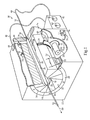
- a molding system 10 including a housing 12 and a plurality of movable blade members 14 defining a cavity 18, and forming an adjustable molding iris 16.
- An elongate tubular body 50 to be used in forming a balloon catheter has been advanced into cavity 18.
- Elongate body 50 includes an end segment 52, a second end segment 54, and a middle segment 56 extending between and adjoining end segments 52 and 54. It can be noted that middle segment 56 is larger in diameter than either of end segments 52 and 54.
- Body 50 may be formed into the configuration shown in Figure 1 by drawing down each of end segments 52 and 54 under heating and tension to leave middle segment 56 in the form it might have from extruding a single tubular piece.
- the starting piece might thus have first and second reduced diameter end segments extending from opposite ends of a larger diameter middle segment, although the present disclosure is not thereby limited.
- the reduced diameter segments When advanced into molding iris 16, the reduced diameter segments will extend from opposite ends of the molding iris approximately as shown.
- Elongate body 50 also has a tubular wall 58 defining a longitudinally extending lumen 66 through each of segments 52, 54 and 56. Lumen 66 further defines a longitudinal axis 60.
- system 10 may be uniquely configured for blow molding elongate body 50, and other suitable elongate bodies, for forming balloon catheters.
- molding iris 16 serves as an adjustable size molding die enabling not only flexibility in molding different size balloon catheters, but also in the techniques applied to mold individual balloon catheters, as further discussed herein.
- system 10 may be configured to increase a temperature of material forming elongate body 50 so as to soften the material, once positioned within the cavity.
- system 10 is equipped with a plurality of resistance heaters 20 attached to or positioned in proximity to movable blade members 14, and connected with an electrical power supply 22. Heated air, heated liquid, radiant heating elements, or any other suitable strategy for increasing a temperature of movable blade members 14 so as to heat material of an elongate body contacting or in proximity to movable blade members 14 could be used.
- Cavity 18 may itself be defined by surfaces 24 of movable blade members 14, which are movable during the adjustment of iris 16.
- movable blade members 14 have the general form of an elongated wedge shape, being generally triangular in cross section. In other instances, movable blade members 14 might have a curved shape, such that surfaces 24 are arcuate rather than planar as shown. It can also be seen that each of movable blade members 14 is positioned in contact with two adjacent movable blade members 14, and slides in contact with the adjacent two blade members during adjustment of iris 16. Also in a practical implementation strategy, blade members 14 may be synchronously pivoted or otherwise synchronously moved to adjust the size of iris 16. Movable blade members 14 may also be mounted within housing 12 via any suitable means, with housing end rings 26 positioned at opposite ends of iris 16. Blade members 14 might be positioned for translational movement in addition to pivoting movement in certain instances.
- the adjustment of movable blade members 14 may further be carried out by way of an actuating mechanism 28 that includes a motor 30, such as a servo motor, and a drive gear 31 coupled between motor 30 and a gear ring 32 that extends circumferentially about movable blade members 14.
- Movable blade members 14 may be coupled with one or more driven elements 34 in mesh with gear ring 32 such that rotation of gear ring 32, in directions shown approximately by way of the curved arrow on gear ring 32 in Figure 1 , adjusts a size of iris 16.
- Actuating mechanism 28 may rotatably support blade members 14 within housing 12, and while only one gear ring is shown in Figure 1 multiple gear rings might be used and positioned at different axial locations about movable blade members 14. Individual electric motors coupled with blade members 14 might be used, pneumatic or hydraulic actuators, or any other suitable mechanical contrivance.
- end support 36 positioned at one end of iris 16.
- end support 36 is one of two end supports, the other of which is positioned at an opposite axial end of iris 16 but omitted from the illustration in Figure 1 .
- Reduced diameter segments 52 and 54 will typically each be positioned within one of the end supports during blow molding.
- End support 36 can be coupled to housing end ring 26, for instance via pins 40. It can be seen that elongate body 50 extends through end support 36, and in particular passes through an aperture 38 formed therein and including a tapered surface 39, having a conical shape and tapered such that surface 39 enlarges in the direction of iris 16.
- end support 36 enables plastic deformation of tubular wall 58 to form a tapered shape via contact with inner surface 39 that limits outward expansion of tubular wall 58.
- End support 36 and the opposite end support not shown, will typically be removable from housing 12 to facilitate advancing elongate body into and out of cavity 18.
- System 10 is further configured to increase a fluid pressure, such as a gaseous fluid pressure, within lumen 66 so as to blow mold a balloon in elongate body 50.
- system 10 further includes a fluid supply 42, which might or might not be coupled to housing 12, and including at least one pump or compressor 43, and potentially an additional pump or compressor 45, with a first fluid line 44 connected to pump 43, and a second fluid line 46 connected to pump 45.
- a cooling air inlet 48 is formed in or coupled to housing 12, so as to enable cooling air or another fluid to be passed through line 46 and into housing 12.
- line 44 fluidly connects with elongate body 50, for increasing a fluid pressure within lumen 66 to blow mold a balloon in elongate body 50.
- tubular wall 58 expands outwardly in response to the increased fluid pressure about longitudinal axis 60. Outward expansion of tubular wall 58 is limited via contacting the expanded tubular wall 58 with movable blade members 14 while molding iris 16 is held in a fixed state, such that upon hardening of the material tubular wall 58 forms an inflatable balloon in fluid communication with lumen 66 in an adjoining segment of tubular body 50, such as segment 52 or segment 54, or both. Lumen 66 may be blocked within segment 52, to enable the increase of fluid pressure within segment 56.
- the fluid used in blow molding may be air, but in other embodiments could be a different gas or even a liquid.
- operator controls 70 mounted to housing 12 and including a first button 72 and a second button 74, which could be used for a variety of purposes, but in one practical implementation strategy will be used for controlling motor 30 and fluid supply 42, respectively. Additional switches, buttons, a GUI, or any other suitable input devices could be provided.
- FIG. 2 there is shown a sectioned view through system 10 and elongate body 50 where iris 16 is held in a fixed state and elongate body 50 has been advanced into cavity 18. Positioning iris 16 in a fixed state prior to supplying the pressurized air into lumen 66 predetermines a configuration of the balloon to be formed. At the process stage shown in Figure 2 , the temperature of material forming elongate body 50 may be increased so as to soften the material, and subsequently fluid pressure within lumen 66 may be increased to plastically deform segment 56 in the manner described herein.
- FIG. 3 there is shown a similar sectioned view where middle segment 56 has been expanded outwardly and tubular wall 58 has contacted blade members 14 so as to limit the outward expansion.
- an approximate first expanded diameter 62 corresponding to the actual expanded diameter of segment 56 is shown.
- iris 16 has been held in a fixed state to determine the configuration, including the diameter, of expanded tubular segment 56.
- a second expanded diameter 64 is shown in Figure 3 , and corresponds to a diameter that might be obtained where iris 16 is held in a different fixed state during the blow molding process.
- embodiments are contemplated where iris 16 is adjusted during the blow molding process to various ends.
- a molding system 110 including an adjustable molding iris 118 formed by a plurality of movable blade members 114 and 114'.
- Movable blade members 114 and 114' define a cavity 116 having an elongate body 150 positioned therein, and in particular including a first segment 155 positioned within a first portion of iris 118 formed by blade members 114, and a second segment 157 positioned within a second portion of iris 118 formed by blade members 114'.
- segments 155 and 157 which may be coaxial about a longitudinal axis 160 but might not be in other embodiments, have different diameters.
- movable blade members 114 and movable blade members 114' are independently adjustable to enable balloons having non-uniform diameters to be molded. Since cavity 118 has a first internal diameter where defined by blade members 114, and a second, larger internal diameter where defined by blade members 114', the balloon formed by blow molding elongate body 150 can have the different shapes shown.
- FIG. 5 there is shown an axial sectioned view of elongate body 50, through middle segment 56, and illustrated as it might appear where movable blade members 14 have been held in a fixed configuration, and pump 45 has been operated in fluid supply 42 to increase fluid pressure within lumen 66.
- Tubular wall 58 has expanded outwardly so that its outward expansion is limited via contact with movable blade members 14.
- material forming elongate body 50 may be increased in temperature and softened via convection of heat from surfaces of blade members 14 and/or via some other heating strategy.
- segment 56 Once segment 56 has been plastically deformed to the state generally desired for a balloon, it may be desirable to hasten hardening of material in elongate body 50 via cooling fluid such as air passed between movable blade members 14, and about tubular wall 58.
- FIG. 6 there is shown elongate body 50 in a view similar to that of Figure 5 , and illustrating in a detailed enlargement where pump 43 has been used to supply cooling air into housing 12, such that the cooling air passes between blade members 14 and about tubular wall 58 to hasten cooling of material forming elongate body 50. Also shown in Figure 6 is pump 45 having been reversed in direction so as to apply a negative pressure to lumen 66 to inwardly deform tubular wall 58 to increase a flow area for the cooling fluid. In Figures 5 and 6 pivot axes 59 for each of movable blade members 14 are also shown.
- movable blade members 14 will be maintained at fixed positions during the blow molding process, hence they will not be adjusted about axes 59 during any individual molding cycle.
- movable blade members 14 might be adjusted to change a size of iris 16 during the blow molding of an individual balloon in an elongate body. For instance, in one example embodiment, as the tubular wall expands outwardly in response to increased fluid pressure blade members 14 might be pivoted about their pivot axes 59 to increase a size of cavity 18. The increasing in size could occur continuously, or in a step-wise manner.
- movable blade members 14 might be maintained at fixed positions until just prior to the point at which cooling air begins to be pumped between them and about the balloon to hasten its cooling. At that point, movable blade members 14 might be pivoted to enlarge iris 18, and assist in the creation of flow space for cooling air.
- Those skilled in the art will envision still further variations that might be obtained by way of the flexibility to adjust the size of iris 18.
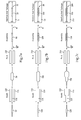
- Figure 7a there is shown an example series of processing steps used in producing an inventory of balloon catheters according to the present disclosure. It will be appreciated that the present description of Figure 7a , and also Figures 7b, 7c and Figure 8 , are applicable to any of the tubular bodies, molding systems, and other apparatus and techniques discussed herein. Similarly, features of the blow molding process described above such as heating, increasing of fluid pressure, application of negative pressure, the use of cooling air, for instance, can all be applied to the production of a balloon catheter inventory as illustrated in Figures 7a-c .
- elongate body 50 is first shown to the left as it might appear prior to being advanced into cavity 118 formed by iris 116 in system 110 at a mold stage of processing.
- Elongate body 50 is processed in system 110 so as to blow mold a first balloon therein while molding iris 116 is held in a first state determining a configuration of the first balloon.
- elongate body 50, with a balloon now formed therein can be advanced to a fold stage, in a known folding or balloon pleating machine 210, and thenceforth to an assembly stage where a proximal fitting and a distal tip are attached to the elongate body with the now folded balloon to form a balloon catheter.
- the elongate body may be advanced to a sterilize and package stage where it is placed within sterile, peel open package 99.
- FIG. 7b there is shown another elongate body 100 as it might appear just prior to being advanced into cavity 118 in place of first elongate 50.
- Second elongate body 100 may be processed so as to blow mold a balloon therein while molding iris 116 is held in a second state determining a configuration of the second balloon.
- elongate body 100 may be forwarded to the fold stage, the assembly stage, and incorporated in a balloon catheter 149 placed within a sterile peel open package 99.
- FIG. 7c there is shown yet another elongate body 150 as it might appear ready to be advanced into cavity 118 with molding iris 116 in yet another configuration, this time with multiple different diameters.
- Elongate body 150 may be molded in molding system 110, and then advanced to a fold stage, an assembly stage, and a sterilize and package stage where it is incorporated into a balloon catheter 249 placed in a sterile, peel open package 199.
- each of Figures 7a, 7b and 7c may represent a production run where a balloon catheter having different characteristics is made. It will further be appreciated that many balloon catheters might be made according to the processing steps as set forth in each of Figures 7a, 7b and 7c .
- iris 116 can be adjusted via moving movable blade members 14. Accordingly, after a plurality of elongate bodies similar to elongate body 50 are blow molded, system 110 may be adjusted and a plurality of elongate bodies similar to 100 formed, and so on.
- the internal diameter of cavity 118 is adjusted, either throughout the cavity as evident from the difference between Figures 7a and 7b , or within the cavity as depicted in Figure 7c .
- the movable blade members may be moved so as to change the internal diameter of molding iris 116 uniformly.
- the blade members may be adjusted so as to change the internal diameter of molding iris 116 to different relative extents at different axial locations.
- FIG. 8 there is shown an inventory of balloon catheters, including one catheter of each of the general kinds shown processed in Figures 7a-c .
- Tip 53 has been affixed to elongate body 50, as has been a fitting 55.
- a plurality of pleats 51 are evident in the now folded balloon formed by middle segment 56. Similar features and components are found in balloon catheters 149 and 249. It is contemplated that the present disclosure will provide efficiency improvements over prior strategies for producing an inventory of balloon catheters.
- the balloon molding iris itself can be adjusted. Changeover in iris size or configuration between production runs, or even adjustments during a production run, can be executed quite rapidly.
- the capability of adjustments to the molding iris provides new opportunities for molding process development not possible with fixed size dies.
Landscapes
- Health & Medical Sciences (AREA)
- Heart & Thoracic Surgery (AREA)
- Engineering & Computer Science (AREA)
- Life Sciences & Earth Sciences (AREA)
- Anesthesiology (AREA)
- Animal Behavior & Ethology (AREA)
- Biophysics (AREA)
- Pulmonology (AREA)
- Manufacturing & Machinery (AREA)
- Biomedical Technology (AREA)
- Hematology (AREA)
- Child & Adolescent Psychology (AREA)
- General Health & Medical Sciences (AREA)
- Public Health (AREA)
- Veterinary Medicine (AREA)
- Mechanical Engineering (AREA)
- Media Introduction/Drainage Providing Device (AREA)
- Blow-Moulding Or Thermoforming Of Plastics Or The Like (AREA)
Applications Claiming Priority (1)
| Application Number | Priority Date | Filing Date | Title |
|---|---|---|---|
| US201462029013P | 2014-07-25 | 2014-07-25 |
Publications (2)
| Publication Number | Publication Date |
|---|---|
| EP2977172A1 true EP2977172A1 (fr) | 2016-01-27 |
| EP2977172B1 EP2977172B1 (fr) | 2019-10-02 |
Family
ID=53365791
Family Applications (1)
| Application Number | Title | Priority Date | Filing Date |
|---|---|---|---|
| EP15169727.3A Active EP2977172B1 (fr) | 2014-07-25 | 2015-05-28 | Procédés pour fabriquer un cathéter à ballonnet et pour produire un inventaire de cathéters à ballonnet |
Country Status (2)
| Country | Link |
|---|---|
| US (1) | US10286192B2 (fr) |
| EP (1) | EP2977172B1 (fr) |
Cited By (1)
| Publication number | Priority date | Publication date | Assignee | Title |
|---|---|---|---|---|
| WO2022112057A1 (fr) * | 2020-11-27 | 2022-06-02 | Bw-Tec Ag | Processus de formation de ballonnet |
Families Citing this family (5)
| Publication number | Priority date | Publication date | Assignee | Title |
|---|---|---|---|---|
| US10696005B2 (en) | 2016-07-29 | 2020-06-30 | Freudenberg Medical, Inc. | Assembly and method of same for mechanically skiving to remove balloon parison tubing materials |
| CN106512184B (zh) * | 2016-12-09 | 2022-06-07 | 江苏常美医疗器械有限公司 | 导管快速夹紧充气装置 |
| JP7485303B2 (ja) * | 2021-03-31 | 2024-05-16 | テルモ株式会社 | 形状付け装置および形状付け方法 |
| JP2022155878A (ja) * | 2021-03-31 | 2022-10-14 | テルモ株式会社 | 形状付け装置 |
| CN115534286A (zh) * | 2022-09-27 | 2022-12-30 | 广东博迈医疗科技股份有限公司 | 球囊料管拉伸装置及球囊料管加工方法 |
Citations (3)
| Publication number | Priority date | Publication date | Assignee | Title |
|---|---|---|---|---|
| US3380121A (en) * | 1965-07-30 | 1968-04-30 | American Can Co | Mold with replaceable inserts |
| JP2002113770A (ja) * | 2000-10-06 | 2002-04-16 | Kanegafuchi Chem Ind Co Ltd | バルーンカテーテル用パリソン |
| US20020125617A1 (en) * | 2001-03-06 | 2002-09-12 | Advanced Cardiovascular Systems, Inc. | Adjustable length mold assemblies |
Family Cites Families (8)
| Publication number | Priority date | Publication date | Assignee | Title |
|---|---|---|---|---|
| DE3516175A1 (de) | 1985-05-06 | 1986-11-06 | Fa. Martin Rudolph, 5620 Velbert | Laengenverstellbare blasform |
| US4789129A (en) | 1987-08-14 | 1988-12-06 | Eastman Kodak Company | Adjustable mold for forming containers |
| US5731013A (en) | 1995-09-13 | 1998-03-24 | The Whitaker Corporation | Reconfigurable mold having travelling separator assist |
| US7892201B1 (en) | 1999-08-27 | 2011-02-22 | Gore Enterprise Holdings, Inc. | Balloon catheter and method of mounting same |
| US6561788B1 (en) | 2000-05-31 | 2003-05-13 | Advanced Cardiovascular Systems, Inc. | Modular mold designs |
| JP2002011377A (ja) | 2000-06-30 | 2002-01-15 | Kobe Steel Ltd | 廃棄合成樹脂類の選別方法および選別システム |
| US8042251B2 (en) * | 2008-05-21 | 2011-10-25 | Boston Scientific Scimed, Inc. | Systems and methods for heating and cooling during stent crimping |
| US8585959B2 (en) | 2010-09-30 | 2013-11-19 | Cook Medical Technologies Llc | Balloon with integrally retained dilation element |
-
2015
- 2015-05-28 EP EP15169727.3A patent/EP2977172B1/fr active Active
- 2015-06-02 US US14/728,235 patent/US10286192B2/en active Active
Patent Citations (3)
| Publication number | Priority date | Publication date | Assignee | Title |
|---|---|---|---|---|
| US3380121A (en) * | 1965-07-30 | 1968-04-30 | American Can Co | Mold with replaceable inserts |
| JP2002113770A (ja) * | 2000-10-06 | 2002-04-16 | Kanegafuchi Chem Ind Co Ltd | バルーンカテーテル用パリソン |
| US20020125617A1 (en) * | 2001-03-06 | 2002-09-12 | Advanced Cardiovascular Systems, Inc. | Adjustable length mold assemblies |
Non-Patent Citations (1)
| Title |
|---|
| DATABASE WPI Week 200271, Derwent World Patents Index; AN 2002-660166, XP002751935 * |
Cited By (1)
| Publication number | Priority date | Publication date | Assignee | Title |
|---|---|---|---|---|
| WO2022112057A1 (fr) * | 2020-11-27 | 2022-06-02 | Bw-Tec Ag | Processus de formation de ballonnet |
Also Published As
| Publication number | Publication date |
|---|---|
| US10286192B2 (en) | 2019-05-14 |
| US20160022967A1 (en) | 2016-01-28 |
| EP2977172B1 (fr) | 2019-10-02 |
Similar Documents
| Publication | Publication Date | Title |
|---|---|---|
| US10286192B2 (en) | Methods for making a balloon catheter and for producing an inventory of balloon catheters | |
| JP3830193B2 (ja) | カテーテル用バルーンの製造方法 | |
| US10207083B2 (en) | Balloon catheter and method for manufacturing balloon | |
| US5645789A (en) | Distensible pet balloon and method of manufacture | |
| US7060218B2 (en) | Adjustable length mold assemblies | |
| JP6260281B2 (ja) | バルーン用チューブ、バルーン、バルーンカテーテル、および、バルーン用チューブの製造方法 | |
| US9533125B2 (en) | Balloon catheter and method of manufacture | |
| JP2018126208A (ja) | 医療用バルーンカテーテル | |
| JP2009528152A (ja) | 新規なバルーンカテーテルの型設計 | |
| JP6812884B2 (ja) | パリソン製造方法およびパリソン製造装置 | |
| US11872744B2 (en) | Parison former | |
| JP4752657B2 (ja) | カテーテル用バルーンおよびその製造方法 | |
| CN118082166A (zh) | 热塑性高分子管材变径薄化模具、设备及其方法 | |
| CN106573131A (zh) | 制造用于血管成形术的气囊的方法 | |
| CN114177489B (zh) | 一种鼓泡球囊的制备方法 | |
| US20250082482A1 (en) | Balloon catheters | |
| KR100887988B1 (ko) | 카테터에 사용되는 풍선부재의 제조방법 | |
| CN116674184B (zh) | 大尺寸球囊的成型系统及其方法 | |
| WO2020184004A1 (fr) | Procédé de production d'un cathéter à ballonnet | |
| CN116653263B (zh) | 大尺寸球囊的制备工艺 | |
| JP2023137344A (ja) | バルーンの形状付け方法 | |
| CN117442851A (zh) | 大尺寸球囊端部拉伸成型工艺 | |
| JP6440159B2 (ja) | バルーン製造用チューブ、バルーン、およびバルーン製造方法 | |
| JP2023137349A (ja) | バルーンカテーテルおよびバルーンの形状付け方法 | |
| CN120080528A (zh) | 一种用于球囊成型的工装夹具及非顺应性球囊成型方法 |
Legal Events
| Date | Code | Title | Description |
|---|---|---|---|
| PUAI | Public reference made under article 153(3) epc to a published international application that has entered the european phase |
Free format text: ORIGINAL CODE: 0009012 |
|
| AK | Designated contracting states |
Kind code of ref document: A1 Designated state(s): AL AT BE BG CH CY CZ DE DK EE ES FI FR GB GR HR HU IE IS IT LI LT LU LV MC MK MT NL NO PL PT RO RS SE SI SK SM TR |
|
| AX | Request for extension of the european patent |
Extension state: BA ME |
|
| 17P | Request for examination filed |
Effective date: 20160727 |
|
| RBV | Designated contracting states (corrected) |
Designated state(s): AL AT BE BG CH CY CZ DE DK EE ES FI FR GB GR HR HU IE IS IT LI LT LU LV MC MK MT NL NO PL PT RO RS SE SI SK SM TR |
|
| STAA | Information on the status of an ep patent application or granted ep patent |
Free format text: STATUS: EXAMINATION IS IN PROGRESS |
|
| 17Q | First examination report despatched |
Effective date: 20170821 |
|
| GRAP | Despatch of communication of intention to grant a patent |
Free format text: ORIGINAL CODE: EPIDOSNIGR1 |
|
| STAA | Information on the status of an ep patent application or granted ep patent |
Free format text: STATUS: GRANT OF PATENT IS INTENDED |
|
| INTG | Intention to grant announced |
Effective date: 20190424 |
|
| GRAS | Grant fee paid |
Free format text: ORIGINAL CODE: EPIDOSNIGR3 |
|
| GRAA | (expected) grant |
Free format text: ORIGINAL CODE: 0009210 |
|
| STAA | Information on the status of an ep patent application or granted ep patent |
Free format text: STATUS: THE PATENT HAS BEEN GRANTED |
|
| AK | Designated contracting states |
Kind code of ref document: B1 Designated state(s): AL AT BE BG CH CY CZ DE DK EE ES FI FR GB GR HR HU IE IS IT LI LT LU LV MC MK MT NL NO PL PT RO RS SE SI SK SM TR |
|
| REG | Reference to a national code |
Ref country code: GB Ref legal event code: FG4D |
|
| REG | Reference to a national code |
Ref country code: CH Ref legal event code: EP Ref country code: AT Ref legal event code: REF Ref document number: 1185708 Country of ref document: AT Kind code of ref document: T Effective date: 20191015 |
|
| REG | Reference to a national code |
Ref country code: IE Ref legal event code: FG4D |
|
| REG | Reference to a national code |
Ref country code: DE Ref legal event code: R096 Ref document number: 602015038939 Country of ref document: DE |
|
| REG | Reference to a national code |
Ref country code: NL Ref legal event code: MP Effective date: 20191002 |
|
| REG | Reference to a national code |
Ref country code: LT Ref legal event code: MG4D |
|
| REG | Reference to a national code |
Ref country code: AT Ref legal event code: MK05 Ref document number: 1185708 Country of ref document: AT Kind code of ref document: T Effective date: 20191002 |
|
| PG25 | Lapsed in a contracting state [announced via postgrant information from national office to epo] |
Ref country code: ES Free format text: LAPSE BECAUSE OF FAILURE TO SUBMIT A TRANSLATION OF THE DESCRIPTION OR TO PAY THE FEE WITHIN THE PRESCRIBED TIME-LIMIT Effective date: 20191002 Ref country code: LT Free format text: LAPSE BECAUSE OF FAILURE TO SUBMIT A TRANSLATION OF THE DESCRIPTION OR TO PAY THE FEE WITHIN THE PRESCRIBED TIME-LIMIT Effective date: 20191002 Ref country code: NL Free format text: LAPSE BECAUSE OF FAILURE TO SUBMIT A TRANSLATION OF THE DESCRIPTION OR TO PAY THE FEE WITHIN THE PRESCRIBED TIME-LIMIT Effective date: 20191002 Ref country code: LV Free format text: LAPSE BECAUSE OF FAILURE TO SUBMIT A TRANSLATION OF THE DESCRIPTION OR TO PAY THE FEE WITHIN THE PRESCRIBED TIME-LIMIT Effective date: 20191002 Ref country code: SE Free format text: LAPSE BECAUSE OF FAILURE TO SUBMIT A TRANSLATION OF THE DESCRIPTION OR TO PAY THE FEE WITHIN THE PRESCRIBED TIME-LIMIT Effective date: 20191002 Ref country code: GR Free format text: LAPSE BECAUSE OF FAILURE TO SUBMIT A TRANSLATION OF THE DESCRIPTION OR TO PAY THE FEE WITHIN THE PRESCRIBED TIME-LIMIT Effective date: 20200103 Ref country code: PL Free format text: LAPSE BECAUSE OF FAILURE TO SUBMIT A TRANSLATION OF THE DESCRIPTION OR TO PAY THE FEE WITHIN THE PRESCRIBED TIME-LIMIT Effective date: 20191002 Ref country code: AT Free format text: LAPSE BECAUSE OF FAILURE TO SUBMIT A TRANSLATION OF THE DESCRIPTION OR TO PAY THE FEE WITHIN THE PRESCRIBED TIME-LIMIT Effective date: 20191002 Ref country code: NO Free format text: LAPSE BECAUSE OF FAILURE TO SUBMIT A TRANSLATION OF THE DESCRIPTION OR TO PAY THE FEE WITHIN THE PRESCRIBED TIME-LIMIT Effective date: 20200102 Ref country code: BG Free format text: LAPSE BECAUSE OF FAILURE TO SUBMIT A TRANSLATION OF THE DESCRIPTION OR TO PAY THE FEE WITHIN THE PRESCRIBED TIME-LIMIT Effective date: 20200102 Ref country code: PT Free format text: LAPSE BECAUSE OF FAILURE TO SUBMIT A TRANSLATION OF THE DESCRIPTION OR TO PAY THE FEE WITHIN THE PRESCRIBED TIME-LIMIT Effective date: 20200203 Ref country code: FI Free format text: LAPSE BECAUSE OF FAILURE TO SUBMIT A TRANSLATION OF THE DESCRIPTION OR TO PAY THE FEE WITHIN THE PRESCRIBED TIME-LIMIT Effective date: 20191002 |
|
| PG25 | Lapsed in a contracting state [announced via postgrant information from national office to epo] |
Ref country code: CZ Free format text: LAPSE BECAUSE OF FAILURE TO SUBMIT A TRANSLATION OF THE DESCRIPTION OR TO PAY THE FEE WITHIN THE PRESCRIBED TIME-LIMIT Effective date: 20191002 Ref country code: RS Free format text: LAPSE BECAUSE OF FAILURE TO SUBMIT A TRANSLATION OF THE DESCRIPTION OR TO PAY THE FEE WITHIN THE PRESCRIBED TIME-LIMIT Effective date: 20191002 Ref country code: IS Free format text: LAPSE BECAUSE OF FAILURE TO SUBMIT A TRANSLATION OF THE DESCRIPTION OR TO PAY THE FEE WITHIN THE PRESCRIBED TIME-LIMIT Effective date: 20200224 Ref country code: HR Free format text: LAPSE BECAUSE OF FAILURE TO SUBMIT A TRANSLATION OF THE DESCRIPTION OR TO PAY THE FEE WITHIN THE PRESCRIBED TIME-LIMIT Effective date: 20191002 |
|
| PG25 | Lapsed in a contracting state [announced via postgrant information from national office to epo] |
Ref country code: AL Free format text: LAPSE BECAUSE OF FAILURE TO SUBMIT A TRANSLATION OF THE DESCRIPTION OR TO PAY THE FEE WITHIN THE PRESCRIBED TIME-LIMIT Effective date: 20191002 |
|
| REG | Reference to a national code |
Ref country code: DE Ref legal event code: R097 Ref document number: 602015038939 Country of ref document: DE |
|
| PG2D | Information on lapse in contracting state deleted |
Ref country code: IS |
|
| PG25 | Lapsed in a contracting state [announced via postgrant information from national office to epo] |
Ref country code: EE Free format text: LAPSE BECAUSE OF FAILURE TO SUBMIT A TRANSLATION OF THE DESCRIPTION OR TO PAY THE FEE WITHIN THE PRESCRIBED TIME-LIMIT Effective date: 20191002 Ref country code: DK Free format text: LAPSE BECAUSE OF FAILURE TO SUBMIT A TRANSLATION OF THE DESCRIPTION OR TO PAY THE FEE WITHIN THE PRESCRIBED TIME-LIMIT Effective date: 20191002 Ref country code: RO Free format text: LAPSE BECAUSE OF FAILURE TO SUBMIT A TRANSLATION OF THE DESCRIPTION OR TO PAY THE FEE WITHIN THE PRESCRIBED TIME-LIMIT Effective date: 20191002 Ref country code: IS Free format text: LAPSE BECAUSE OF FAILURE TO SUBMIT A TRANSLATION OF THE DESCRIPTION OR TO PAY THE FEE WITHIN THE PRESCRIBED TIME-LIMIT Effective date: 20200202 |
|
| PLBE | No opposition filed within time limit |
Free format text: ORIGINAL CODE: 0009261 |
|
| STAA | Information on the status of an ep patent application or granted ep patent |
Free format text: STATUS: NO OPPOSITION FILED WITHIN TIME LIMIT |
|
| PG25 | Lapsed in a contracting state [announced via postgrant information from national office to epo] |
Ref country code: SK Free format text: LAPSE BECAUSE OF FAILURE TO SUBMIT A TRANSLATION OF THE DESCRIPTION OR TO PAY THE FEE WITHIN THE PRESCRIBED TIME-LIMIT Effective date: 20191002 Ref country code: IT Free format text: LAPSE BECAUSE OF FAILURE TO SUBMIT A TRANSLATION OF THE DESCRIPTION OR TO PAY THE FEE WITHIN THE PRESCRIBED TIME-LIMIT Effective date: 20191002 Ref country code: SM Free format text: LAPSE BECAUSE OF FAILURE TO SUBMIT A TRANSLATION OF THE DESCRIPTION OR TO PAY THE FEE WITHIN THE PRESCRIBED TIME-LIMIT Effective date: 20191002 |
|
| 26N | No opposition filed |
Effective date: 20200703 |
|
| PG25 | Lapsed in a contracting state [announced via postgrant information from national office to epo] |
Ref country code: SI Free format text: LAPSE BECAUSE OF FAILURE TO SUBMIT A TRANSLATION OF THE DESCRIPTION OR TO PAY THE FEE WITHIN THE PRESCRIBED TIME-LIMIT Effective date: 20191002 |
|
| PG25 | Lapsed in a contracting state [announced via postgrant information from national office to epo] |
Ref country code: MC Free format text: LAPSE BECAUSE OF FAILURE TO SUBMIT A TRANSLATION OF THE DESCRIPTION OR TO PAY THE FEE WITHIN THE PRESCRIBED TIME-LIMIT Effective date: 20191002 Ref country code: CH Free format text: LAPSE BECAUSE OF NON-PAYMENT OF DUE FEES Effective date: 20200531 Ref country code: LI Free format text: LAPSE BECAUSE OF NON-PAYMENT OF DUE FEES Effective date: 20200531 |
|
| REG | Reference to a national code |
Ref country code: BE Ref legal event code: MM Effective date: 20200531 |
|
| PG25 | Lapsed in a contracting state [announced via postgrant information from national office to epo] |
Ref country code: LU Free format text: LAPSE BECAUSE OF NON-PAYMENT OF DUE FEES Effective date: 20200528 |
|
| PG25 | Lapsed in a contracting state [announced via postgrant information from national office to epo] |
Ref country code: FR Free format text: LAPSE BECAUSE OF NON-PAYMENT OF DUE FEES Effective date: 20200531 |
|
| PG25 | Lapsed in a contracting state [announced via postgrant information from national office to epo] |
Ref country code: BE Free format text: LAPSE BECAUSE OF NON-PAYMENT OF DUE FEES Effective date: 20200531 |
|
| PG25 | Lapsed in a contracting state [announced via postgrant information from national office to epo] |
Ref country code: TR Free format text: LAPSE BECAUSE OF FAILURE TO SUBMIT A TRANSLATION OF THE DESCRIPTION OR TO PAY THE FEE WITHIN THE PRESCRIBED TIME-LIMIT Effective date: 20191002 Ref country code: MT Free format text: LAPSE BECAUSE OF FAILURE TO SUBMIT A TRANSLATION OF THE DESCRIPTION OR TO PAY THE FEE WITHIN THE PRESCRIBED TIME-LIMIT Effective date: 20191002 Ref country code: CY Free format text: LAPSE BECAUSE OF FAILURE TO SUBMIT A TRANSLATION OF THE DESCRIPTION OR TO PAY THE FEE WITHIN THE PRESCRIBED TIME-LIMIT Effective date: 20191002 |
|
| PG25 | Lapsed in a contracting state [announced via postgrant information from national office to epo] |
Ref country code: MK Free format text: LAPSE BECAUSE OF FAILURE TO SUBMIT A TRANSLATION OF THE DESCRIPTION OR TO PAY THE FEE WITHIN THE PRESCRIBED TIME-LIMIT Effective date: 20191002 |
|
| P01 | Opt-out of the competence of the unified patent court (upc) registered |
Effective date: 20230602 |
|
| PGFP | Annual fee paid to national office [announced via postgrant information from national office to epo] |
Ref country code: DE Payment date: 20250528 Year of fee payment: 11 |
|
| PGFP | Annual fee paid to national office [announced via postgrant information from national office to epo] |
Ref country code: GB Payment date: 20250520 Year of fee payment: 11 |
|
| PGFP | Annual fee paid to national office [announced via postgrant information from national office to epo] |
Ref country code: IE Payment date: 20250520 Year of fee payment: 11 |