EP2977190B1 - Procédé et dispositif pour panser les zones endommagées dans des matériaux composites fibreux - Google Patents
Procédé et dispositif pour panser les zones endommagées dans des matériaux composites fibreux Download PDFInfo
- Publication number
- EP2977190B1 EP2977190B1 EP15173105.6A EP15173105A EP2977190B1 EP 2977190 B1 EP2977190 B1 EP 2977190B1 EP 15173105 A EP15173105 A EP 15173105A EP 2977190 B1 EP2977190 B1 EP 2977190B1
- Authority
- EP
- European Patent Office
- Prior art keywords
- fibre
- fibre layer
- delaminating
- layer
- composite component
- Prior art date
- Legal status (The legal status is an assumption and is not a legal conclusion. Google has not performed a legal analysis and makes no representation as to the accuracy of the status listed.)
- Not-in-force
Links
- 239000000835 fiber Substances 0.000 title claims description 253
- 239000002131 composite material Substances 0.000 title claims description 82
- 238000000034 method Methods 0.000 title claims description 38
- 238000005520 cutting process Methods 0.000 claims description 55
- 239000000463 material Substances 0.000 claims description 28
- 238000002604 ultrasonography Methods 0.000 claims description 6
- 238000005259 measurement Methods 0.000 claims description 3
- 238000000926 separation method Methods 0.000 claims description 2
- 230000008439 repair process Effects 0.000 description 8
- 229920002430 Fibre-reinforced plastic Polymers 0.000 description 6
- 239000000853 adhesive Substances 0.000 description 6
- 230000001070 adhesive effect Effects 0.000 description 6
- 230000032798 delamination Effects 0.000 description 6
- 239000011151 fibre-reinforced plastic Substances 0.000 description 6
- 238000003754 machining Methods 0.000 description 5
- 238000010586 diagram Methods 0.000 description 3
- 230000000694 effects Effects 0.000 description 3
- 238000000227 grinding Methods 0.000 description 3
- 238000009659 non-destructive testing Methods 0.000 description 3
- 238000004026 adhesive bonding Methods 0.000 description 2
- 238000011109 contamination Methods 0.000 description 2
- 238000003698 laser cutting Methods 0.000 description 2
- 239000011159 matrix material Substances 0.000 description 2
- 239000003973 paint Substances 0.000 description 2
- 230000008569 process Effects 0.000 description 2
- 239000002699 waste material Substances 0.000 description 2
- XLYOFNOQVPJJNP-UHFFFAOYSA-N water Substances O XLYOFNOQVPJJNP-UHFFFAOYSA-N 0.000 description 2
- 239000004696 Poly ether ether ketone Substances 0.000 description 1
- 239000004697 Polyetherimide Substances 0.000 description 1
- 230000004913 activation Effects 0.000 description 1
- 230000001419 dependent effect Effects 0.000 description 1
- 230000001066 destructive effect Effects 0.000 description 1
- 238000009826 distribution Methods 0.000 description 1
- 239000003822 epoxy resin Substances 0.000 description 1
- 238000007689 inspection Methods 0.000 description 1
- 239000007788 liquid Substances 0.000 description 1
- 238000003801 milling Methods 0.000 description 1
- 238000012986 modification Methods 0.000 description 1
- 230000004048 modification Effects 0.000 description 1
- 238000001020 plasma etching Methods 0.000 description 1
- 239000004033 plastic Substances 0.000 description 1
- 229920003023 plastic Polymers 0.000 description 1
- 229920001643 poly(ether ketone) Polymers 0.000 description 1
- 229920001652 poly(etherketoneketone) Polymers 0.000 description 1
- 229920000647 polyepoxide Polymers 0.000 description 1
- 229920002530 polyetherether ketone Polymers 0.000 description 1
- 229920001601 polyetherimide Polymers 0.000 description 1
- 238000002360 preparation method Methods 0.000 description 1
- 230000009467 reduction Effects 0.000 description 1
- 238000005096 rolling process Methods 0.000 description 1
- 230000003068 static effect Effects 0.000 description 1
- 238000004381 surface treatment Methods 0.000 description 1
- 229920001169 thermoplastic Polymers 0.000 description 1
- 229920001187 thermosetting polymer Polymers 0.000 description 1
- 239000004416 thermosoftening plastic Substances 0.000 description 1
Images
Classifications
-
- B—PERFORMING OPERATIONS; TRANSPORTING
- B29—WORKING OF PLASTICS; WORKING OF SUBSTANCES IN A PLASTIC STATE IN GENERAL
- B29C—SHAPING OR JOINING OF PLASTICS; SHAPING OF MATERIAL IN A PLASTIC STATE, NOT OTHERWISE PROVIDED FOR; AFTER-TREATMENT OF THE SHAPED PRODUCTS, e.g. REPAIRING
- B29C73/00—Repairing of articles made from plastics or substances in a plastic state, e.g. of articles shaped or produced by using techniques covered by this subclass or subclass B29D
- B29C73/24—Apparatus or accessories not otherwise provided for
- B29C73/26—Apparatus or accessories not otherwise provided for for mechanical pretreatment
-
- B—PERFORMING OPERATIONS; TRANSPORTING
- B32—LAYERED PRODUCTS
- B32B—LAYERED PRODUCTS, i.e. PRODUCTS BUILT-UP OF STRATA OF FLAT OR NON-FLAT, e.g. CELLULAR OR HONEYCOMB, FORM
- B32B43/00—Operations specially adapted for layered products and not otherwise provided for, e.g. repairing; Apparatus therefor
- B32B43/006—Delaminating
-
- B—PERFORMING OPERATIONS; TRANSPORTING
- B29—WORKING OF PLASTICS; WORKING OF SUBSTANCES IN A PLASTIC STATE IN GENERAL
- B29C—SHAPING OR JOINING OF PLASTICS; SHAPING OF MATERIAL IN A PLASTIC STATE, NOT OTHERWISE PROVIDED FOR; AFTER-TREATMENT OF THE SHAPED PRODUCTS, e.g. REPAIRING
- B29C69/00—Combinations of shaping techniques not provided for in a single one of main groups B29C39/00 - B29C67/00, e.g. associations of moulding and joining techniques; Apparatus therefore
- B29C69/005—Combinations of shaping techniques not provided for in a single one of main groups B29C39/00 - B29C67/00, e.g. associations of moulding and joining techniques; Apparatus therefore cutting-off or cutting-out a part of a strip-like or sheet-like material, transferring that part and fixing it to an article
-
- B—PERFORMING OPERATIONS; TRANSPORTING
- B32—LAYERED PRODUCTS
- B32B—LAYERED PRODUCTS, i.e. PRODUCTS BUILT-UP OF STRATA OF FLAT OR NON-FLAT, e.g. CELLULAR OR HONEYCOMB, FORM
- B32B38/00—Ancillary operations in connection with laminating processes
- B32B38/0004—Cutting, tearing or severing, e.g. bursting; Cutter details
-
- B—PERFORMING OPERATIONS; TRANSPORTING
- B32—LAYERED PRODUCTS
- B32B—LAYERED PRODUCTS, i.e. PRODUCTS BUILT-UP OF STRATA OF FLAT OR NON-FLAT, e.g. CELLULAR OR HONEYCOMB, FORM
- B32B38/00—Ancillary operations in connection with laminating processes
- B32B38/10—Removing layers, or parts of layers, mechanically or chemically
-
- B—PERFORMING OPERATIONS; TRANSPORTING
- B29—WORKING OF PLASTICS; WORKING OF SUBSTANCES IN A PLASTIC STATE IN GENERAL
- B29C—SHAPING OR JOINING OF PLASTICS; SHAPING OF MATERIAL IN A PLASTIC STATE, NOT OTHERWISE PROVIDED FOR; AFTER-TREATMENT OF THE SHAPED PRODUCTS, e.g. REPAIRING
- B29C73/00—Repairing of articles made from plastics or substances in a plastic state, e.g. of articles shaped or produced by using techniques covered by this subclass or subclass B29D
- B29C73/24—Apparatus or accessories not otherwise provided for
- B29C73/26—Apparatus or accessories not otherwise provided for for mechanical pretreatment
- B29C2073/264—Apparatus or accessories not otherwise provided for for mechanical pretreatment for cutting out or grooving the area to be repaired
-
- B—PERFORMING OPERATIONS; TRANSPORTING
- B32—LAYERED PRODUCTS
- B32B—LAYERED PRODUCTS, i.e. PRODUCTS BUILT-UP OF STRATA OF FLAT OR NON-FLAT, e.g. CELLULAR OR HONEYCOMB, FORM
- B32B43/00—Operations specially adapted for layered products and not otherwise provided for, e.g. repairing; Apparatus therefor
- B32B43/003—Cutting
Definitions
- the present invention relates to a method and to a device for mending damaged areas in fibre composite components, in particular on carbon-fibre-reinforced plastics (CFRP) components for use in the field of aviation and aerospace.
- CFRP carbon-fibre-reinforced plastics
- Fibre-reinforced-plastics (FRP) components which are damaged have to be repaired accordingly, as described for example in Baker, A.A.; Dutton, S.; Kelly, D.: “Composite Materials for Aircraft Structures", 2nd ed., American Institute of Aeronautics and Astronautics Education Series, Blacksburg, Virginia, USA, Chapter 10, pp. 369-401 .
- the damaged components are usually analysed as to the extent of the damage.
- a predetermined region around the damaged area is subsequently removed from the component.
- a blank made of undamaged fibre layers can subsequently be fitted into the cleared region and glued to the edge of the cleared region.
- DE 40 19 744 A1 discloses a device for repairing a component made of fibre composite materials, which comprises a grinding device for stripping material in the region of a damaged area in the component.
- EP 2 644 366 A1 discloses a method for repairing laminated composite components in which, after a repair region around a damaged area in a fibre composite material is identified and defined, damaged fibre layers can be removed individually.
- DE 199 43 751 A1 discloses a known method for mending damaged areas in fibre composite components and a device according to the preamble of claim 10.
- a first aspect of the invention therefore provides a method for mending damaged areas in fibre composite components formed from a plurality of unidirectional fibre layers, comprising the steps of automatically lifting at least one fibre layer of the fibre composite component at a cutting edge of the at least one fibre layer using a delaminating device, removing the at least one fibre layer in the extension direction of the fibre orientation of the at least one fibre layer, and separating off the removed at least one fibre layer in a defined manner at a separating edge defined by a separation device placed on the fibre composite component.
- a second aspect of the invention further provides a device for mending damaged areas in fibre composite components formed from a plurality of unidirectional fibre layers, comprising a delaminating device configured to lift at least one fibre layer of the fibre composite component automatically at a cutting edge of the at least one fibre layer and to remove the at least one fibre layer in the extension direction of the fibre orientation of the at least one fibre layer, a separating device configured to be placed on the fibre composite component so as to produce a cutting edge at which the removed at least one fibre layer can be separated off from the fibre composite component by the delaminating device, and a control device configured to control the delaminating device and the separating device in an automated manner.
- a delaminating device configured to lift at least one fibre layer of the fibre composite component automatically at a cutting edge of the at least one fibre layer and to remove the at least one fibre layer in the extension direction of the fibre orientation of the at least one fibre layer
- a separating device configured to be placed on the fibre composite component so as to produce a cutting edge at which the removed at
- the damaged area preparation can proceed in an automated manner. This greatly increases the throughput of fibre composite components to be repaired. The repair can be carried out very precisely, since only the fibre layers or fibre layer regions which are actually damaged are removed separately and as required.
- the method may further comprise the step of forming the cutting edge of the at least one fibre layer by cutting perpendicularly through the at least one fibre layer using a cutting device.
- a cutting device for example at the edge of the fibre composite component, so as to be able to place the delaminating device on the fibre composite component.
- a cut may be made selectively in the centre of a fibre composite component so as to separate out the fibre layers from the fibre composite component only in regions.
- the cutting edge of the at least one fibre layer may be formed by cutting perpendicularly through the at least one fibre layer using a cutting device.
- the step of non-invasively determining the depth of the damage to the damaged area to be mended of the fibre composite component may further be carried out using a sensor device, for example using an ultrasound sensor, an eddy current sensor, an infrared sensor or a radar sensor.
- the delaminating device may comprise a delaminating blade which is guided under the fibre layer when the at least one fibre layer of the fibre composite component is automatically lifted.
- the delaminating blade may comprise two wedge-shaped blade parts which are pressed together so as to grip the at least one fibre layer when the at least one fibre layer is removed.
- the delaminating device may further comprise a cutting collection device, on which the removed fibre material is laid after the at least one fibre layer is removed.
- a cutting collection device on which the removed fibre material is laid after the at least one fibre layer is removed.
- the cutting collection device it is possible for the cutting collection device to comprise a cylindrical drum on which the removed fibre material is rolled up after the at least one fibre layer is removed.
- the delaminating device may comprise a gripping device which acts adhesively on the fibre layer surface, the gripping device being placed on the fibre layer to remove the at least one fibre layer and being moved diagonally upwards away from the surface of the fibre composite component.
- the device may further comprise a cutting device configured to form a cutting edge of the at least one fibre layer by cutting perpendicularly through the at least one fibre layer.
- the device may further comprise a sensor device configured to determine the depth of the damage to the damaged area to be mended of the fibre composite component by non-invasive measurement, for example an ultrasound sensor, an eddy current sensor, an infrared sensor or a radar sensor.
- a sensor device configured to determine the depth of the damage to the damaged area to be mended of the fibre composite component by non-invasive measurement, for example an ultrasound sensor, an eddy current sensor, an infrared sensor or a radar sensor.
- the delaminating device may comprise a delaminating blade configured to be guided under the fibre layer so as to lift the at least one fibre layer of the fibre composite component automatically.
- the delaminating blade may comprise two wedge-shaped blade parts configured to be pressed together so as to grip the at least one fibre layer when the at least one fibre layer is removed.
- the delaminating device may comprise a gripping device which acts adhesively on the fibre layer surface and which is configured to be placed on the fibre layer so as to remove the at least one fibre layer and to be moved diagonally upwards away from the surface of the fibre composite component.
- the device may further comprise a cutting collection device having a cylindrical drum configured to roll up removed fibre material.
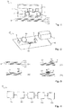
- Fig. 1 is a schematic illustration of a device 10 for mending damaged areas in fibre composite components, for example a fibre composite component B constructed from a plurality of fibre layers L1 to L4 each having a unidirectional fibre orientation.
- unidirectional fibre orientation in a fibre layer means a transversely isotropic fibre layer of a fibre-reinforced-plastics composite in which all of the fibres are orientated in a single direction.
- the fibres may ideally be laid in parallel and with a homogeneous distribution.
- the abbreviated term "unidirectional fibre layers" is used for fibre layers having a unidirectional fibre orientation.
- Fig. 1 - and also Fig. 3(A) - each show four fibre layers L1 to L4, although any other number of fibre layers is also possible.
- the underlying principle of the invention is not dependent on the number of fibre layers in the fibre composite component B, and the solutions according to the invention can be used for fibre composite components B having in principle any number of fibre layers L1 to L4.
- a fibre composite component B may for example be a carbon-fibre-reinforced plastics (CFRP) component for use in the field of aviation and aerospace, which is provided for example with a thermoset matrix such as epoxy resin or with a thermoplastic matrix for example of polyetherketone, polyetheretherketone, polyetherketoneketone, polyphenylenesulphide or polyetherimide.
- CFRP carbon-fibre-reinforced plastics
- the device 10 for mending damaged areas in fibre composite components B may comprise an active machining head 3, which can be guided over the fibre composite component B depending on the desired machining region.
- a delamination device 4 may be provided, which is configured to lift at least one fibre layer L1 of the fibre composite component B automatically at a cutting edge of the at least one fibre layer L1.
- the delamination device 4 can remove the at least one fibre layer L1 in the extension direction of the fibre orientation of the at least one fibre layer L1.
- the delamination device 4 may comprise for example a delaminating blade 4a, which is guided under the at least one fibre layer L1 of the fibre composite component B and peels off the fibre layer L1 from the fibre layers L2 to L4 located underneath.
- the delaminating blade 4a may comprise for example two wedge-shaped blade parts, as shown by way of example in Fig. 3(B) .
- the lower wedge-shaped blade part is placed on the cutting edge of the fibre layer L1 and guided under the fibre layer L1.
- the delaminating blade 4a is subsequently moved over the surface of the fibre composite component B along the movement direction v, in other words counter to the opening direction of the wedge angle of the blade.
- the fibre composite component B may of course also be moved in the opposite direction under the delaminating blade 4a.
- Fig. 3(D) shows by way of example that the two wedge-shaped blade parts can be pressed together in a clamping movement h, so as to be able to grip the fibre layer L1 and separate it from the remaining fibre layers L2 to L4 in an upward releasing movement.
- the device 10 may have a cutting collection device 4b, for example a cylindrical drum, a receiving reel or a winch, configured to roll up removed fibre material.
- the peeled-off fibre material is thus collected in the cutting collection device 4b for disposal, so as to be able to prevent contaminations to the surface of the fibre composite component B by waste products when the damaged area is being mended.
- the cutting collection device 4b may also promote the delaminating effect of the delaminating blade 4a.
- the rolling-up movement of peeled-off fibre material about the cutting collection device 4b may lead to a tensile force on the strips of the fibre layer L1 which are to be removed.
- the drum of the cutting collection device 4b may be moved over the fibre layer surface in a rolling movement to facilitate peeling off the fibre layer L1.
- the width of the peeled-off fibre material depends on the width of the delaminating device 4.
- the delaminating device 4 is guided in the direction of the fibre orientation of the unidirectional fibre layers L1, in such a way that adjacent fibres always extend in parallel at the edge of the delaminating device 4.
- the adhesive forces at the edge of the delaminating device 4 are very small, and the fibre material can be peeled off in strips easily, or without significant adhesive resistance.
- a gripping device which acts adhesively on the fibre layer surface instead of a delaminating blade for the delaminating device 4.
- a vacuum-based gripping tool may be placed on the fibre layer L1 and be moved diagonally upwards from the surface of the fibre composite component B so as to be able to remove the fibre layer L1 from the surface in strips.
- an adhesive can also be applied to the fibre layer L1 in the region of the fibre material to be removed, in such a way that a mechanical gripping tool adheres to the fibre layer L1 locally by means of the adhesive.
- the local adhesive force of the delaminating device 4 on the fibre material is greater than the adhesive force between the fibre layer to be removed and the fibre layer located underneath.
- a strip of fibre material can be removed from the cutting edge away from the fibre composite component B.
- a separating device 6 which can be placed on the fibre composite component B is provided in the device 10.
- the separating device 6 may comprise for example a cutting edge, a sharp-edged tool, a tool having a low edge radius, or a template which can produce a separating edge at the point of application at which the removed fibre layer L1 can be separated off from the fibre composite component B.
- the fibre layer L1 is separated by controlled tearing at the separating edge.
- the machining head 3 may for example further comprise a cutting device 5, such as a knife, a blade, a saw, a grinding tool, a laser cutting device, a milling tool or a water jet cutting device, configured to form a cutting edge in the fibre layer L1 by cutting perpendicularly through the fibre layer L1.
- the delaminating device 4 can be placed on this cutting edge so as to remove fibre material from the fibre layer L1 from the fibre composite component B.
- the region in which fibre material is separated off from the fibre layer L1 by the delaminating device is therefore determined by the position of the cutting edge and the separating edge.
- the device 10 therefore comprises a control device 2 configured to control the delaminating device, the separating device 6 and optionally the cutting device 5 in an automated manner.
- the control may for example take place as a function of sensor signals of a sensor device 7 provided in the device 10, which is configured to determine the depth of the damage to the damaged area to be mended of the fibre composite component B by non-invasive measurement.
- the sensor device 7 can be used for non-destructive testing (NDT) or non-destructive inspection (NDI) of the fibre composite component B.
- NDT non-destructive testing
- NDI non-destructive inspection
- mechanical, structural and/or electrical properties of the fibre composite component B are tested without damaging the material of the fibre composite component B itself.
- Non-destructive testing methods may be carried our statically or dynamically, in other words by measuring a static electrical or magnetic field or by measuring a dynamic wave amplitude, for example an acoustic or electromagnetic wave.
- the sensor device 7 may comprise an ultrasound sensor, an eddy current sensor, an infrared sensor, a radar sensor or another suitable sensor type. Using the sensor device 7, as well as analysing the depth of the damaged fibre layers, among other things the thickness of paint layers or the thickness of lightning protection paints or panels on the fibre composite component B can be tested.
- the device 10 may in each case determine regions for each of the fibre layers L1 to L4 in which strips of fibre material can be removed by selectively positioning cutting edges and/or separating edges. For this purpose, after the removal of fibre material from a fibre layer L1 which is placed higher, the device 10 may accordingly cut one or more fibre layers L2 to L4 located underneath which are cleared by the removal, so as in turn to remove fibre material from the lower-lying fibre layers L2 to L4.
- a depression which clears a predefined three-dimensional region about all of the damaged points in the fibre composite component B can be created in the fibre composite component B.
- the depression may optionally subsequently be further prepared, for example by surface treatment by plasma etching, laser cutting, grinding, water jet treatment or similar surface activation measures.
- the damaged point can subsequently be mended again using various repair measures, for example by gluing in "fibre plasters", by injecting and curing liquid plastics material, by riveting, by gluing or using other suitable repair measures.
- Fig. 4 is a block diagram of a method M for mending damaged areas in fibre composite components, for example of carbon-fibre-reinforced plastics (CFRP) components formed of a plurality of unidirectional fibre layers.
- CFRP carbon-fibre-reinforced plastics
- a device for mending damaged areas in fibre composite components may be used, for example a device 10 as described in connection with Fig. 1 to 3 .
- a first step M1 before the damaged area is actually mended may comprise non-invasive determination of the depth of the damage to the damaged area to be mended of the fibre composite component B, by a sensor device 7, for example an ultrasound sensor, an eddy current sensor, an infrared sensor or a radar sensor.
- a sensor device 7 for example an ultrasound sensor, an eddy current sensor, an infrared sensor or a radar sensor.
- a region to be mended can be established, and is defined in a step M2 by repeatedly forming cutting edges of the fibre layer lying on the surface in each case by cutting perpendicularly through the fibre layer using a cutting device 5.
- a step 3 at least one fibre layer of the fibre composite component B is automatically lifted at a cutting edge of the at least one fibre layer using a delaminating device 4.
- the fibre layer can be removed in the extension direction of the fibre orientation of the fibre layer, for example by moving the delaminating device 4 over the surface and optionally away from the surface of the fibre composite component B.
- the removed fibre layer is subsequently separated off in step M5.
- Steps M2 to M5 may advantageously be repeated, lower-lying fibre layers being cleared by removing fibre material from a fibre layer which is currently locally positioned at the surface of the fibre composite component B in each case, and being prepared accordingly in the next repetition of steps M2 to M5.
- the delaminating device 4 may for example comprise a delaminating blade 4a which is guided under the fibre layer when the fibre layer of the fibre composite component is automatically lifted in step M3.
- the delaminating blade 4a may comprise two wedge-shaped blade parts, which are pressed together so as to grip the fibre layer when the fibre layer is removed in step M4.
- the removed fibre material may for example be stored in a cutting collection device 4b.
- the cutting collection device 4b may for example comprise a cylindrical drum, a receiving roller or a winch, on which the removed fibre material is rolled up after the removal in step M4.
Landscapes
- Engineering & Computer Science (AREA)
- Mechanical Engineering (AREA)
- Treatment Of Fiber Materials (AREA)
- Reinforced Plastic Materials (AREA)
- Physics & Mathematics (AREA)
- Fluid Mechanics (AREA)
Claims (17)
- Procédé (M) de réparation de zones endommagées dans des éléments en composite de fibres (B) formés à partir d'une pluralité de couches de fibres unidirectionnelles (L1 ; L2 ; L3 ; L4), comprenant les étapes consistant à :soulever automatiquement (M3) au moins une couche de fibres (L1) de l'élément en composite de fibres (B) au niveau d'un bord franc de ladite au moins une couche de fibres (L1), à l'aide d'un dispositif de décollement (4) ;enlever (M4) ladite au moins une couche de fibres (L1) dans la direction d'extension de l'orientation des fibres de ladite au moins une couche de fibres (L1) ; etséparer (M5) ladite au moins une couche de fibres enlevée (L1) de manière définie, au niveau d'un bord de séparation défini par un dispositif de séparation (6) placé sur l'élément en composite de fibres (B).
- Procédé (M) selon la revendication 1, comprenant en outre l'étape consistant à :former (M2) le bord franc de ladite au moins une couche de fibres (L1) en taillant perpendiculairement à travers la couche de fibres (L1) à l'aide d'un dispositif de coupe (5).
- Procédé (M) selon l'une des revendications 1 et 2, comprenant en outre l'étape consistant à :déterminer sans pénétration (M1) la profondeur du dommage subi par la zone endommagée à réparer de l'élément en composite de fibres (B), à l'aide d'un dispositif formant capteur (7).
- Procédé (M) selon la revendication 3, dans lequel le dispositif formant capteur (7) comprend un capteur ultrasonore, un capteur à courants de Foucault, un capteur infrarouge ou un capteur radar.
- Procédé (M) selon l'une quelconque des revendications 1 à 4, dans lequel le dispositif de décollement (4) comprend une lame de décollement (4a) qui est guidée sous la couche de fibres (L1) lorsque ladite au moins une couche de fibres (L1) de l'élément en composite de fibres (B) est soulevée automatiquement (M3).
- Procédé (M) selon la revendication 5, dans lequel la lame de décollement (4a) comprend deux parties de lame en forme de coin qui sont pressées ensemble de manière à saisir ladite au moins une couche de fibres (L1) lorsque ladite au moins une couche de fibres (L1) est enlevée (M4).
- Procédé (M) selon l'une des revendications 5 et 6, dans lequel le dispositif de décollement (4) comprend en outre un dispositif collecteur de découpe (4b), sur lequel le matériau en fibres enlevé est posé après que ladite au moins une couche de fibres (L1) a été enlevée (M4).
- Procédé (M) selon la revendication 7, dans lequel le dispositif collecteur de découpe (4b) comprend un tambour cylindrique sur lequel le matériau en fibres enlevé est enroulé après que ladite au moins une couche de fibres (L1) est a été enlevée (M4).
- Procédé (M) selon l'une quelconque des revendications 1 à 4, dans lequel le dispositif de décollement (4) comprend un dispositif de prise qui agit par adhérence sur la surface de la couche de fibres, et dans lequel le dispositif de prise est placé sur la couche de fibres (L1) pour enlever ladite au moins une couche de fibres (L1) et est déplacé en diagonale vers le haut à l'écart de la surface de l'élément en composite de fibres (B).
- Dispositif (10) destiné à réparer des zones endommagées dans des éléments en composite de fibres (B), comprenant :un dispositif de décollement (4) conçu pour soulever automatiquement au moins une couche de fibres (L1) de l'élément en composite de fibres (B) au niveau d'un bord franc de ladite au moins une couche de fibres (L1) etpour enlever ladite au moins une couche de fibres (L1) dans la direction d'extension de l'orientation des fibres de ladite au moins une couche de fibres (L1), caractérisé en ce que le dispositif comprend en outre :un dispositif de séparation (6) conçu pour être placé sur l'élément en composite de fibres (B), de manière à produire un bord franc au niveau duquel ladite au moins une couche de fibres enlevée (L1) peut être séparée de l'élément en composite de fibres (B) par le dispositif de décollement (4) ; etun dispositif de commande (2) conçu pour commander le dispositif de décollement (4) et le dispositif de séparation (6) de façon automatisée.
- Dispositif (10) selon la revendication 10, comprenant en outre :un dispositif de coupe (5) conçu pour former un bord franc de ladite au moins une couche de fibres (L1) en taillant perpendiculairement à travers ladite au moins une couche de fibres (L1).
- Dispositif (10) selon l'une des revendications 10 et 11, comprenant en outre :un dispositif formant capteur (7) conçu pour déterminer la profondeur du dommage subi par la zone endommagée à réparer de l'élément en composite de fibres (B), par mesure sans pénétration.
- Dispositif (10) selon la revendication 12, dans lequel le dispositif formant capteur (7) comprend un capteur ultrasonore, un capteur à courants de Foucault, un capteur infrarouge ou un capteur radar.
- Dispositif (10) selon l'une quelconque des revendications 10 à 13, dans lequel le dispositif de décollement (4) comprend une lame de décollement (4a) conçue pour être guidée sous la couche de fibres (L1), de manière à soulever automatiquement ladite au moins une couche de fibres (L1) de l'élément en composite de fibres (B).
- Dispositif (10) selon la revendication 14, dans lequel la lame de décollement (4a) comprend deux parties de lame en forme de coin, conçues pour être pressées ensemble de manière à saisir ladite au moins une couche de fibres (L1) lorsque ladite au moins une couche de fibres (L1) est enlevée.
- Dispositif (10) selon l'une des revendications 14 et 15, comprenant en outre :un dispositif collecteur de découpe (4b) comportant un tambour cylindrique conçu pour enrouler le matériau en fibres enlevé.
- Dispositif (10) selon l'une quelconque des revendications 10 à 13, dans lequel le dispositif de décollement (4) comprend un dispositif de prise qui agit par adhérence sur la surface de la couche de fibres et qui est conçu pour être placé sur la couche de fibres (L1), de manière à enlever ladite au moins une couche de fibres (L1) et pour être déplacé en diagonale vers le haut à l'écart de la surface de l'élément en composite de fibres (B).
Applications Claiming Priority (1)
| Application Number | Priority Date | Filing Date | Title |
|---|---|---|---|
| DE102014214570.8A DE102014214570A1 (de) | 2014-07-24 | 2014-07-24 | Verfahren und Vorrichtung zur Schadstellenausbesserung an Faserverbundbauteilen |
Publications (2)
| Publication Number | Publication Date |
|---|---|
| EP2977190A1 EP2977190A1 (fr) | 2016-01-27 |
| EP2977190B1 true EP2977190B1 (fr) | 2017-03-29 |
Family
ID=53489849
Family Applications (1)
| Application Number | Title | Priority Date | Filing Date |
|---|---|---|---|
| EP15173105.6A Not-in-force EP2977190B1 (fr) | 2014-07-24 | 2015-06-22 | Procédé et dispositif pour panser les zones endommagées dans des matériaux composites fibreux |
Country Status (3)
| Country | Link |
|---|---|
| US (1) | US10538073B2 (fr) |
| EP (1) | EP2977190B1 (fr) |
| DE (1) | DE102014214570A1 (fr) |
Cited By (1)
| Publication number | Priority date | Publication date | Assignee | Title |
|---|---|---|---|---|
| US10538073B2 (en) | 2014-07-24 | 2020-01-21 | Airbus Operations Gmbh | Method and device for mending damaged areas in fiber composite components |
Families Citing this family (7)
| Publication number | Priority date | Publication date | Assignee | Title |
|---|---|---|---|---|
| DE102016117559A1 (de) * | 2016-09-19 | 2018-03-22 | Fraunhofer-Gesellschaft zur Förderung der angewandten Forschung e.V. | Verfahren und Vorrichtung für das Recycling von thermoplastischem Faserverbundmaterial |
| DE102017127635A1 (de) * | 2017-11-22 | 2019-05-23 | Wobben Properties Gmbh | Bauteil für eine Windenergieanlage sowie Verfahren zum Herstellen und Verfahren zum Prüfen des Bauteils |
| DE102018125133A1 (de) * | 2018-10-11 | 2020-04-16 | Airbus Operations Gmbh | System und ein Verfahren zum Herstellen eines Bauteils aus einem Faserverbundmaterial |
| WO2020229530A1 (fr) * | 2019-05-14 | 2020-11-19 | Lm Wind Power A/S | Fabrication d'une partie coque de pale d'éolienne |
| EP3995279A1 (fr) * | 2020-11-05 | 2022-05-11 | Fraunhofer-Gesellschaft zur Förderung der angewandten Forschung e.V. | Procédé et dispositif de recyclage d'un matériau compris à plusieurs couches |
| FR3124423B1 (fr) * | 2021-06-24 | 2023-05-19 | Safran Aircraft Engines | Procede de reparation d’une aube composite de turbomachine |
| US11571883B1 (en) * | 2021-12-30 | 2023-02-07 | Rohr, Inc. | Thermoplastic laminate induction welding system and method |
Family Cites Families (15)
| Publication number | Priority date | Publication date | Assignee | Title |
|---|---|---|---|---|
| DE4019744C2 (de) | 1990-06-21 | 1994-05-26 | Poly Id Ag Steckborn | Vorrichtung zum Reparieren von Bauteilen aus Kunststoff, insbesondere aus Faserverbundwerkstoffen |
| DE19720845A1 (de) * | 1997-05-17 | 1998-11-19 | Arra Terra Recycling Gmbh | Verfahren zum Trennen von Metall-Kunststoff-Verbundplatten |
| US6358358B1 (en) * | 1999-09-07 | 2002-03-19 | Thomas Bilisoly | Method and apparatus for producing signs with a weeding and laminating system |
| DE19943751B4 (de) * | 1999-09-13 | 2008-04-03 | Bayerische Motoren Werke Ag | Trennverfahren |
| DE102005025096A1 (de) * | 2005-06-01 | 2006-12-07 | Airbus Deutschland Gmbh | Verfahren zur Verbindung eines mit einem Kunststoffmaterial gebildeten ersten Bauteils mit einem zweiten Bauteil sowie Verbindungselement und Vorrichtung |
| TWI335899B (en) * | 2006-11-03 | 2011-01-11 | Kodak Graphic Comm Canada Co | Methods and apparatus for peeling a flexible sheet from a substrate |
| DE112007003624A5 (de) * | 2007-06-19 | 2010-05-20 | Slcr Lasertechnik Gmbh | Verfahren zum Abtragen von faserverstärkten Kunststoffen, die aus mindestens zwei unterschiedlichen Materialien bestehen |
| US8524020B2 (en) * | 2009-06-16 | 2013-09-03 | The Boeing Company | Method of restoring a composite airframe |
| DE102010004570B4 (de) * | 2010-01-12 | 2011-09-22 | Tutech Innovation Gmbh | Verfahren zum Fräsen von langfaserverstärkten Verbundkunststoffen |
| WO2011112936A1 (fr) * | 2010-03-12 | 2011-09-15 | High Voltage Graphics, Inc. | Articles floqués offrant une résistance à la déchirure et procédés pour fabriquer ceux-ci |
| KR101818473B1 (ko) * | 2011-11-30 | 2018-01-16 | 엘지디스플레이 주식회사 | 보호필름 박리장치 및 박리방법 |
| US9849640B2 (en) | 2012-03-28 | 2017-12-26 | Bell Helicopter Textron Inc. | Processes for repairing complex laminated composites |
| US20140079922A1 (en) * | 2012-09-17 | 2014-03-20 | Svaya Nanotechnologies, Inc | Methods for encapsulating Layer by Layer films and for preparing specialized optical films |
| DE202013002818U1 (de) * | 2013-03-25 | 2013-04-17 | Harro Höfliger Verpackungsmaschinen GmbH | Vorrichtung zum Ablösen einer Materialschicht von einer mehrere Materialschichten umfassenden Materialbahn |
| DE102014214570A1 (de) | 2014-07-24 | 2016-01-28 | Airbus Operations Gmbh | Verfahren und Vorrichtung zur Schadstellenausbesserung an Faserverbundbauteilen |
-
2014
- 2014-07-24 DE DE102014214570.8A patent/DE102014214570A1/de not_active Withdrawn
-
2015
- 2015-06-22 EP EP15173105.6A patent/EP2977190B1/fr not_active Not-in-force
- 2015-07-21 US US14/804,807 patent/US10538073B2/en active Active
Cited By (1)
| Publication number | Priority date | Publication date | Assignee | Title |
|---|---|---|---|---|
| US10538073B2 (en) | 2014-07-24 | 2020-01-21 | Airbus Operations Gmbh | Method and device for mending damaged areas in fiber composite components |
Also Published As
| Publication number | Publication date |
|---|---|
| US20160023450A1 (en) | 2016-01-28 |
| DE102014214570A1 (de) | 2016-01-28 |
| US10538073B2 (en) | 2020-01-21 |
| EP2977190A1 (fr) | 2016-01-27 |
Similar Documents
| Publication | Publication Date | Title |
|---|---|---|
| EP2977190B1 (fr) | Procédé et dispositif pour panser les zones endommagées dans des matériaux composites fibreux | |
| CA2695851C (fr) | Structure composite stratifiee | |
| EP3412440B1 (fr) | Outil de gabarit de réparation composite rapide et procédé associé | |
| US20150251401A1 (en) | Repair apparatus and method for composite panels having a conductive layer | |
| JP7080223B2 (ja) | 熱可塑性の繊維複合材料をリサイクルするための方法及び装置 | |
| US20150059142A1 (en) | Repair of a damaged composite structure | |
| US7823490B2 (en) | Cutting sequence for net trimming a composite layup at an oblique angle | |
| EP3661709B1 (fr) | Dispositif pour la découpe des films avec un actuateur lineaire | |
| Gu et al. | Acoustic emission characterization of a notched aluminum plate repaired with a fiber composite patch | |
| EP4234219B1 (fr) | Retouche structurelle de panneaux de noyaux cellulaires | |
| EP3578455B1 (fr) | Longerons d'aéronef dotés de brides renforcées en matériau cfrp | |
| EP3137288A1 (fr) | Pièce structurale liée à motif adhésif conique | |
| JP2019104238A (ja) | 複合修繕キット | |
| CN105372327A (zh) | 基于十字阵和波数扫描滤波器的在线损伤成像方法 | |
| CN114986948A (zh) | 复合材料蜂窝夹心结构的修理工艺及方法 | |
| Stepanova et al. | Studying the failure of a CFRP sample under static loading by the acoustic-emission and fractography methods | |
| EP2982478A1 (fr) | Système automatisé et procédé de lissage de matériau plissé | |
| EP4628677A1 (fr) | Procédé de décollement de film à partir d'un film de démoulage | |
| US9579855B2 (en) | Secondary groove for work piece retention during machining | |
| EP3144129B1 (fr) | Élément de référence pour un composant composite | |
| CN206489062U (zh) | 一种涂层附着力测试切割装置 | |
| EP3023231B1 (fr) | Systèmes et procédés pour compacter une charge de matériau composite | |
| SUHARA et al. | Development of quick repair method for aircraft composite structures | |
| JP3606674B2 (ja) | 薄切片の作製方法およびそのための装置 | |
| US20240181725A1 (en) | Trimming and Scrap Removal System for Composite Structures |
Legal Events
| Date | Code | Title | Description |
|---|---|---|---|
| PUAI | Public reference made under article 153(3) epc to a published international application that has entered the european phase |
Free format text: ORIGINAL CODE: 0009012 |
|
| AK | Designated contracting states |
Kind code of ref document: A1 Designated state(s): AL AT BE BG CH CY CZ DE DK EE ES FI FR GB GR HR HU IE IS IT LI LT LU LV MC MK MT NL NO PL PT RO RS SE SI SK SM TR |
|
| AX | Request for extension of the european patent |
Extension state: BA ME |
|
| 17P | Request for examination filed |
Effective date: 20160713 |
|
| RBV | Designated contracting states (corrected) |
Designated state(s): AL AT BE BG CH CY CZ DE DK EE ES FI FR GB GR HR HU IE IS IT LI LT LU LV MC MK MT NL NO PL PT RO RS SE SI SK SM TR |
|
| GRAP | Despatch of communication of intention to grant a patent |
Free format text: ORIGINAL CODE: EPIDOSNIGR1 |
|
| STAA | Information on the status of an ep patent application or granted ep patent |
Free format text: STATUS: GRANT OF PATENT IS INTENDED |
|
| INTG | Intention to grant announced |
Effective date: 20161222 |
|
| GRAS | Grant fee paid |
Free format text: ORIGINAL CODE: EPIDOSNIGR3 |
|
| GRAA | (expected) grant |
Free format text: ORIGINAL CODE: 0009210 |
|
| STAA | Information on the status of an ep patent application or granted ep patent |
Free format text: STATUS: THE PATENT HAS BEEN GRANTED |
|
| AK | Designated contracting states |
Kind code of ref document: B1 Designated state(s): AL AT BE BG CH CY CZ DE DK EE ES FI FR GB GR HR HU IE IS IT LI LT LU LV MC MK MT NL NO PL PT RO RS SE SI SK SM TR |
|
| REG | Reference to a national code |
Ref country code: GB Ref legal event code: FG4D |
|
| REG | Reference to a national code |
Ref country code: CH Ref legal event code: EP |
|
| REG | Reference to a national code |
Ref country code: AT Ref legal event code: REF Ref document number: 879326 Country of ref document: AT Kind code of ref document: T Effective date: 20170415 |
|
| REG | Reference to a national code |
Ref country code: IE Ref legal event code: FG4D |
|
| REG | Reference to a national code |
Ref country code: DE Ref legal event code: R096 Ref document number: 602015001984 Country of ref document: DE |
|
| REG | Reference to a national code |
Ref country code: FR Ref legal event code: PLFP Year of fee payment: 3 |
|
| PG25 | Lapsed in a contracting state [announced via postgrant information from national office to epo] |
Ref country code: NO Free format text: LAPSE BECAUSE OF FAILURE TO SUBMIT A TRANSLATION OF THE DESCRIPTION OR TO PAY THE FEE WITHIN THE PRESCRIBED TIME-LIMIT Effective date: 20170629 Ref country code: GR Free format text: LAPSE BECAUSE OF FAILURE TO SUBMIT A TRANSLATION OF THE DESCRIPTION OR TO PAY THE FEE WITHIN THE PRESCRIBED TIME-LIMIT Effective date: 20170630 Ref country code: HR Free format text: LAPSE BECAUSE OF FAILURE TO SUBMIT A TRANSLATION OF THE DESCRIPTION OR TO PAY THE FEE WITHIN THE PRESCRIBED TIME-LIMIT Effective date: 20170329 Ref country code: LT Free format text: LAPSE BECAUSE OF FAILURE TO SUBMIT A TRANSLATION OF THE DESCRIPTION OR TO PAY THE FEE WITHIN THE PRESCRIBED TIME-LIMIT Effective date: 20170329 Ref country code: FI Free format text: LAPSE BECAUSE OF FAILURE TO SUBMIT A TRANSLATION OF THE DESCRIPTION OR TO PAY THE FEE WITHIN THE PRESCRIBED TIME-LIMIT Effective date: 20170329 |
|
| REG | Reference to a national code |
Ref country code: NL Ref legal event code: MP Effective date: 20170329 |
|
| REG | Reference to a national code |
Ref country code: AT Ref legal event code: MK05 Ref document number: 879326 Country of ref document: AT Kind code of ref document: T Effective date: 20170329 |
|
| PG25 | Lapsed in a contracting state [announced via postgrant information from national office to epo] |
Ref country code: BG Free format text: LAPSE BECAUSE OF FAILURE TO SUBMIT A TRANSLATION OF THE DESCRIPTION OR TO PAY THE FEE WITHIN THE PRESCRIBED TIME-LIMIT Effective date: 20170629 Ref country code: RS Free format text: LAPSE BECAUSE OF FAILURE TO SUBMIT A TRANSLATION OF THE DESCRIPTION OR TO PAY THE FEE WITHIN THE PRESCRIBED TIME-LIMIT Effective date: 20170329 Ref country code: LV Free format text: LAPSE BECAUSE OF FAILURE TO SUBMIT A TRANSLATION OF THE DESCRIPTION OR TO PAY THE FEE WITHIN THE PRESCRIBED TIME-LIMIT Effective date: 20170329 Ref country code: SE Free format text: LAPSE BECAUSE OF FAILURE TO SUBMIT A TRANSLATION OF THE DESCRIPTION OR TO PAY THE FEE WITHIN THE PRESCRIBED TIME-LIMIT Effective date: 20170329 |
|
| PG25 | Lapsed in a contracting state [announced via postgrant information from national office to epo] |
Ref country code: NL Free format text: LAPSE BECAUSE OF FAILURE TO SUBMIT A TRANSLATION OF THE DESCRIPTION OR TO PAY THE FEE WITHIN THE PRESCRIBED TIME-LIMIT Effective date: 20170329 |
|
| PG25 | Lapsed in a contracting state [announced via postgrant information from national office to epo] |
Ref country code: CZ Free format text: LAPSE BECAUSE OF FAILURE TO SUBMIT A TRANSLATION OF THE DESCRIPTION OR TO PAY THE FEE WITHIN THE PRESCRIBED TIME-LIMIT Effective date: 20170329 Ref country code: IT Free format text: LAPSE BECAUSE OF FAILURE TO SUBMIT A TRANSLATION OF THE DESCRIPTION OR TO PAY THE FEE WITHIN THE PRESCRIBED TIME-LIMIT Effective date: 20170329 Ref country code: SK Free format text: LAPSE BECAUSE OF FAILURE TO SUBMIT A TRANSLATION OF THE DESCRIPTION OR TO PAY THE FEE WITHIN THE PRESCRIBED TIME-LIMIT Effective date: 20170329 Ref country code: EE Free format text: LAPSE BECAUSE OF FAILURE TO SUBMIT A TRANSLATION OF THE DESCRIPTION OR TO PAY THE FEE WITHIN THE PRESCRIBED TIME-LIMIT Effective date: 20170329 Ref country code: RO Free format text: LAPSE BECAUSE OF FAILURE TO SUBMIT A TRANSLATION OF THE DESCRIPTION OR TO PAY THE FEE WITHIN THE PRESCRIBED TIME-LIMIT Effective date: 20170329 Ref country code: ES Free format text: LAPSE BECAUSE OF FAILURE TO SUBMIT A TRANSLATION OF THE DESCRIPTION OR TO PAY THE FEE WITHIN THE PRESCRIBED TIME-LIMIT Effective date: 20170329 Ref country code: AT Free format text: LAPSE BECAUSE OF FAILURE TO SUBMIT A TRANSLATION OF THE DESCRIPTION OR TO PAY THE FEE WITHIN THE PRESCRIBED TIME-LIMIT Effective date: 20170329 |
|
| PG25 | Lapsed in a contracting state [announced via postgrant information from national office to epo] |
Ref country code: PL Free format text: LAPSE BECAUSE OF FAILURE TO SUBMIT A TRANSLATION OF THE DESCRIPTION OR TO PAY THE FEE WITHIN THE PRESCRIBED TIME-LIMIT Effective date: 20170329 Ref country code: SM Free format text: LAPSE BECAUSE OF FAILURE TO SUBMIT A TRANSLATION OF THE DESCRIPTION OR TO PAY THE FEE WITHIN THE PRESCRIBED TIME-LIMIT Effective date: 20170329 Ref country code: IS Free format text: LAPSE BECAUSE OF FAILURE TO SUBMIT A TRANSLATION OF THE DESCRIPTION OR TO PAY THE FEE WITHIN THE PRESCRIBED TIME-LIMIT Effective date: 20170729 |
|
| REG | Reference to a national code |
Ref country code: DE Ref legal event code: R097 Ref document number: 602015001984 Country of ref document: DE |
|
| PG25 | Lapsed in a contracting state [announced via postgrant information from national office to epo] |
Ref country code: DK Free format text: LAPSE BECAUSE OF FAILURE TO SUBMIT A TRANSLATION OF THE DESCRIPTION OR TO PAY THE FEE WITHIN THE PRESCRIBED TIME-LIMIT Effective date: 20170329 Ref country code: MC Free format text: LAPSE BECAUSE OF FAILURE TO SUBMIT A TRANSLATION OF THE DESCRIPTION OR TO PAY THE FEE WITHIN THE PRESCRIBED TIME-LIMIT Effective date: 20170329 |
|
| PLBE | No opposition filed within time limit |
Free format text: ORIGINAL CODE: 0009261 |
|
| STAA | Information on the status of an ep patent application or granted ep patent |
Free format text: STATUS: NO OPPOSITION FILED WITHIN TIME LIMIT |
|
| 26N | No opposition filed |
Effective date: 20180103 |
|
| REG | Reference to a national code |
Ref country code: IE Ref legal event code: MM4A |
|
| PG25 | Lapsed in a contracting state [announced via postgrant information from national office to epo] |
Ref country code: IE Free format text: LAPSE BECAUSE OF NON-PAYMENT OF DUE FEES Effective date: 20170622 Ref country code: LU Free format text: LAPSE BECAUSE OF NON-PAYMENT OF DUE FEES Effective date: 20170622 |
|
| REG | Reference to a national code |
Ref country code: BE Ref legal event code: MM Effective date: 20170630 |
|
| PG25 | Lapsed in a contracting state [announced via postgrant information from national office to epo] |
Ref country code: SI Free format text: LAPSE BECAUSE OF FAILURE TO SUBMIT A TRANSLATION OF THE DESCRIPTION OR TO PAY THE FEE WITHIN THE PRESCRIBED TIME-LIMIT Effective date: 20170329 |
|
| REG | Reference to a national code |
Ref country code: FR Ref legal event code: PLFP Year of fee payment: 4 |
|
| PG25 | Lapsed in a contracting state [announced via postgrant information from national office to epo] |
Ref country code: BE Free format text: LAPSE BECAUSE OF NON-PAYMENT OF DUE FEES Effective date: 20170630 |
|
| PG25 | Lapsed in a contracting state [announced via postgrant information from national office to epo] |
Ref country code: MT Free format text: LAPSE BECAUSE OF NON-PAYMENT OF DUE FEES Effective date: 20170622 |
|
| REG | Reference to a national code |
Ref country code: CH Ref legal event code: PL |
|
| PG25 | Lapsed in a contracting state [announced via postgrant information from national office to epo] |
Ref country code: LI Free format text: LAPSE BECAUSE OF NON-PAYMENT OF DUE FEES Effective date: 20180630 Ref country code: CH Free format text: LAPSE BECAUSE OF NON-PAYMENT OF DUE FEES Effective date: 20180630 |
|
| PG25 | Lapsed in a contracting state [announced via postgrant information from national office to epo] |
Ref country code: HU Free format text: LAPSE BECAUSE OF FAILURE TO SUBMIT A TRANSLATION OF THE DESCRIPTION OR TO PAY THE FEE WITHIN THE PRESCRIBED TIME-LIMIT; INVALID AB INITIO Effective date: 20150622 |
|
| PG25 | Lapsed in a contracting state [announced via postgrant information from national office to epo] |
Ref country code: CY Free format text: LAPSE BECAUSE OF FAILURE TO SUBMIT A TRANSLATION OF THE DESCRIPTION OR TO PAY THE FEE WITHIN THE PRESCRIBED TIME-LIMIT Effective date: 20170329 |
|
| PG25 | Lapsed in a contracting state [announced via postgrant information from national office to epo] |
Ref country code: MK Free format text: LAPSE BECAUSE OF FAILURE TO SUBMIT A TRANSLATION OF THE DESCRIPTION OR TO PAY THE FEE WITHIN THE PRESCRIBED TIME-LIMIT Effective date: 20170329 |
|
| PG25 | Lapsed in a contracting state [announced via postgrant information from national office to epo] |
Ref country code: TR Free format text: LAPSE BECAUSE OF FAILURE TO SUBMIT A TRANSLATION OF THE DESCRIPTION OR TO PAY THE FEE WITHIN THE PRESCRIBED TIME-LIMIT Effective date: 20170329 |
|
| PG25 | Lapsed in a contracting state [announced via postgrant information from national office to epo] |
Ref country code: PT Free format text: LAPSE BECAUSE OF FAILURE TO SUBMIT A TRANSLATION OF THE DESCRIPTION OR TO PAY THE FEE WITHIN THE PRESCRIBED TIME-LIMIT Effective date: 20170329 |
|
| PG25 | Lapsed in a contracting state [announced via postgrant information from national office to epo] |
Ref country code: AL Free format text: LAPSE BECAUSE OF FAILURE TO SUBMIT A TRANSLATION OF THE DESCRIPTION OR TO PAY THE FEE WITHIN THE PRESCRIBED TIME-LIMIT Effective date: 20170329 |
|
| PGFP | Annual fee paid to national office [announced via postgrant information from national office to epo] |
Ref country code: GB Payment date: 20220627 Year of fee payment: 8 Ref country code: DE Payment date: 20220620 Year of fee payment: 8 |
|
| PGFP | Annual fee paid to national office [announced via postgrant information from national office to epo] |
Ref country code: FR Payment date: 20220628 Year of fee payment: 8 |
|
| REG | Reference to a national code |
Ref country code: DE Ref legal event code: R119 Ref document number: 602015001984 Country of ref document: DE |
|
| GBPC | Gb: european patent ceased through non-payment of renewal fee |
Effective date: 20230622 |
|
| PG25 | Lapsed in a contracting state [announced via postgrant information from national office to epo] |
Ref country code: DE Free format text: LAPSE BECAUSE OF NON-PAYMENT OF DUE FEES Effective date: 20240103 Ref country code: GB Free format text: LAPSE BECAUSE OF NON-PAYMENT OF DUE FEES Effective date: 20230622 |
|
| PG25 | Lapsed in a contracting state [announced via postgrant information from national office to epo] |
Ref country code: FR Free format text: LAPSE BECAUSE OF NON-PAYMENT OF DUE FEES Effective date: 20230630 |