EP2977228B1 - Luftreifen für flugzeuge - Google Patents
Luftreifen für flugzeuge Download PDFInfo
- Publication number
- EP2977228B1 EP2977228B1 EP14768507.7A EP14768507A EP2977228B1 EP 2977228 B1 EP2977228 B1 EP 2977228B1 EP 14768507 A EP14768507 A EP 14768507A EP 2977228 B1 EP2977228 B1 EP 2977228B1
- Authority
- EP
- European Patent Office
- Prior art keywords
- tire
- cord
- cords
- width
- tread
- Prior art date
- Legal status (The legal status is an assumption and is not a legal conclusion. Google has not performed a legal analysis and makes no representation as to the accuracy of the status listed.)
- Not-in-force
Links
Images

Classifications
-
- B—PERFORMING OPERATIONS; TRANSPORTING
- B60—VEHICLES IN GENERAL
- B60C—VEHICLE TYRES; TYRE INFLATION; TYRE CHANGING; CONNECTING VALVES TO INFLATABLE ELASTIC BODIES IN GENERAL; DEVICES OR ARRANGEMENTS RELATED TO TYRES
- B60C9/00—Reinforcements or ply arrangement of pneumatic tyres
- B60C9/0057—Reinforcements comprising preshaped elements, e.g. undulated or zig-zag filaments
-
- B—PERFORMING OPERATIONS; TRANSPORTING
- B60—VEHICLES IN GENERAL
- B60C—VEHICLE TYRES; TYRE INFLATION; TYRE CHANGING; CONNECTING VALVES TO INFLATABLE ELASTIC BODIES IN GENERAL; DEVICES OR ARRANGEMENTS RELATED TO TYRES
- B60C11/00—Tyre tread bands; Tread patterns; Anti-skid inserts
- B60C11/03—Tread patterns
- B60C11/04—Tread patterns in which the raised area of the pattern consists only of continuous circumferential ribs, e.g. zig-zag
-
- B—PERFORMING OPERATIONS; TRANSPORTING
- B60—VEHICLES IN GENERAL
- B60C—VEHICLE TYRES; TYRE INFLATION; TYRE CHANGING; CONNECTING VALVES TO INFLATABLE ELASTIC BODIES IN GENERAL; DEVICES OR ARRANGEMENTS RELATED TO TYRES
- B60C9/00—Reinforcements or ply arrangement of pneumatic tyres
- B60C9/18—Structure or arrangement of belts or breakers, crown-reinforcing or cushioning layers
- B60C9/20—Structure or arrangement of belts or breakers, crown-reinforcing or cushioning layers built-up from rubberised plies each having all cords arranged substantially parallel
- B60C9/2003—Structure or arrangement of belts or breakers, crown-reinforcing or cushioning layers built-up from rubberised plies each having all cords arranged substantially parallel characterised by the materials of the belt cords
- B60C9/2009—Structure or arrangement of belts or breakers, crown-reinforcing or cushioning layers built-up from rubberised plies each having all cords arranged substantially parallel characterised by the materials of the belt cords comprising plies of different materials
-
- B—PERFORMING OPERATIONS; TRANSPORTING
- B60—VEHICLES IN GENERAL
- B60C—VEHICLE TYRES; TYRE INFLATION; TYRE CHANGING; CONNECTING VALVES TO INFLATABLE ELASTIC BODIES IN GENERAL; DEVICES OR ARRANGEMENTS RELATED TO TYRES
- B60C9/00—Reinforcements or ply arrangement of pneumatic tyres
- B60C9/18—Structure or arrangement of belts or breakers, crown-reinforcing or cushioning layers
- B60C9/20—Structure or arrangement of belts or breakers, crown-reinforcing or cushioning layers built-up from rubberised plies each having all cords arranged substantially parallel
- B60C2009/2012—Structure or arrangement of belts or breakers, crown-reinforcing or cushioning layers built-up from rubberised plies each having all cords arranged substantially parallel with particular configuration of the belt cords in the respective belt layers
- B60C2009/2032—Structure or arrangement of belts or breakers, crown-reinforcing or cushioning layers built-up from rubberised plies each having all cords arranged substantially parallel with particular configuration of the belt cords in the respective belt layers characterised by the course of the belt cords, e.g. undulated or sinusoidal
-
- B—PERFORMING OPERATIONS; TRANSPORTING
- B60—VEHICLES IN GENERAL
- B60C—VEHICLE TYRES; TYRE INFLATION; TYRE CHANGING; CONNECTING VALVES TO INFLATABLE ELASTIC BODIES IN GENERAL; DEVICES OR ARRANGEMENTS RELATED TO TYRES
- B60C9/00—Reinforcements or ply arrangement of pneumatic tyres
- B60C9/18—Structure or arrangement of belts or breakers, crown-reinforcing or cushioning layers
- B60C9/20—Structure or arrangement of belts or breakers, crown-reinforcing or cushioning layers built-up from rubberised plies each having all cords arranged substantially parallel
- B60C9/22—Structure or arrangement of belts or breakers, crown-reinforcing or cushioning layers built-up from rubberised plies each having all cords arranged substantially parallel the plies being arranged with all cords disposed along the circumference of the tyre
- B60C2009/2252—Physical properties or dimension of the zero degree ply cords
- B60C2009/229—Physical properties or dimension of the zero degree ply cords characterised by the course of the cords, e.g. undulated or sinusoidal
-
- B—PERFORMING OPERATIONS; TRANSPORTING
- B60—VEHICLES IN GENERAL
- B60C—VEHICLE TYRES; TYRE INFLATION; TYRE CHANGING; CONNECTING VALVES TO INFLATABLE ELASTIC BODIES IN GENERAL; DEVICES OR ARRANGEMENTS RELATED TO TYRES
- B60C2200/00—Tyres specially adapted for particular applications
- B60C2200/02—Tyres specially adapted for particular applications for aircrafts
Definitions
- the present invention relates to an aircraft pneumatic tire.
- the above tread protection layer is configured with plural cords extending in the tire circumferential direction that are arrayed in the tire width direction and are coated in rubber.
- the circumferential length of the tread increases as the diameter of the tire lengthens when internal pressure is charged in the tire, and the cords of the tread protection layer are stretched.
- each of the cords is formed in a wave shape with an amplitude in the tire width direction, thereby securing room for elongation in advance.
- an object of the present invention is to increase the room for elongation of a tread protection layer, while securing durability.
- An aircraft pneumatic tire includes a tread protection layer that is provided at a lower layer of a tread section, and that includes a plurality of cords that are arrayed in a tire width direction and are each disposed along a wave shaped imaginary line extending along a tire circumferential direction with the tire width direction as the amplitude direction, wherein the cords in the tread protection layer include plural cord discontinuity portions along the tire circumferential direction.
- a second aspect of the present invention is the aircraft pneumatic tire according to the first aspect, wherein the cords are formed in a sine wave shape as viewed in tread plan view, and the cord discontinuity portions include positions corresponding to inflection points of the sine waves.
- the cord discontinuity portions include the positions corresponding to inflection points of the sine waves, and so the adjacent cords are not liable to interfere with each other even when the amplitude of the cords is made large in the tire width direction.
- the sine wave shaped cords are accordingly suppressed from interfering with each other, enabling durability to be secured.
- a third aspect of the present invention is the aircraft pneumatic tire according to the first aspect or the second aspect, wherein: the tread section is partitioned by plural circumferential direction grooves extending along the tire circumferential direction into a wide-width rib positioned at a tire width direction central portion, and into narrow-width ribs positioned at the tire width direction outer sides of the wide-width rib; and a tire circumferential direction interval between one of the cord discontinuity portions and another of the cord discontinuity portions is narrower in a region corresponding to the wide-width rib than in the regions corresponding to the narrow-width ribs.
- the wide-width rib of the tread section is positioned at a tire width direction central portion where the diametrical length increase is largest during charging internal pressure.
- the interval in the tire circumferential direction between one of the cord discontinuity portions and another of the cord discontinuity portions is set narrower in a region corresponding to the wide-width rib than in the regions corresponding to the narrow-width ribs.
- the room for elongation in the wide-width rib in the tread protection layer is thereby larger than the room for elongation in the narrow-width ribs. This thereby enables the room for elongation of the tread protection layer to be made appropriate to the differences in diametrical length increase of the respective ribs.
- the aircraft pneumatic tire according to the present invention obtains the excellent advantageous effect of enabling the room for elongation of the tread protection layer to be increased, while securing durability.
- the arrow C direction indicates the tire circumferential direction
- the arrow R direction indicates the tire radial direction
- the arrow W direction indicates the tire width direction.
- the tire radial direction means a direction orthogonal to the tire rotation axis (not illustrated in the drawings).
- the tire width direction means a direction parallel to the tire rotation axis. References to the tire width direction may be interchanged with the tire axial direction.
- an aircraft pneumatic tire 10 is, for example, a radial tire, and includes a tread protection layer 12.
- the aircraft pneumatic tire 10 includes a carcass ply 16, a belt layer 18, and a reinforcement layer 20.
- the belt layer 18 is provided at the tire radial direction outside of the carcass ply 16, and is configured by winding a rubber covered cord 26 along a tire circumferential direction in a spiral shape.
- Organic fiber, steel, or the like is employed as the material of the cord 26.
- the belt layer 18 is not limited to being a single layer, and may be configured by plural layers.
- the reinforcement layer 20 is provided at the tire radial direction outside of the belt layer 18, and is configured by employing plural strands of cord 28 that are disposed at an angle to the tire circumferential direction.
- the cords 28 are configured so as to reverse at the edges of the reinforcement layer 20 so as to intersect with each other, however, there is no limitation thereto, and a configuration may be adopted in which the cords 28 do not intersect with each other.
- Organic fiber or the like is employed as the material of the cord 28.
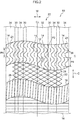
- the tread protection layer 12 is provided at a lower layer of a tread section 22, and includes plural cords 24 that are arrayed in the tire width direction and are each disposed along a wave shaped imaginary line extending along the tire circumferential direction, with the tire width direction as the amplitude direction.
- the tread protection layer 12 is positioned at the tire radial direction outside of the reinforcement layer 20.
- Organic fiber or the like is employed in the material of the cord 24.
- the cords 24 are formed, for example, in a sine wave shape in a plan view of the tread.
- the cord 24 in the tread protection layer 12 includes cord discontinuity portions 14 in the tire circumferential direction.
- the cord discontinuity portions 14 are locations where the cords 24 in close proximity to each other are partially omitted in the tread protection layer 12, and are, for example, provided in every other cord 24.
- the cord discontinuity portions 14 include positions corresponding to inflection points 36 of sine waves.
- the cord discontinuity portions 14 include the inflection points 36, and are provided at both sides of the inflection points 36 in the portions between maximum amplitude points and minimum amplitude points.
- the inflection points 36 are points where the center of circular arc portions configuring the wave shape switch from being positioned in the tire width direction on one side of the cord to being positioned on the other side of the cord.
- the cords 24 are closest to each other in the vicinity of the inflection points 36. Namely, the vicinity of the inflection points 36 are locations of close proximity between the cords 24. The cords 24 are omitted at these locations of close proximity due to being susceptible to mutual interference. In other words, the cords 24 are partially interrupted and replaced with rubber at the cord discontinuity portions 14.
- the tread section 22 is partitioned by plural circumferential direction grooves 30 extending along the tire circumferential direction, into a wide-width rib 32 positioned at a tire width direction central portion and narrow-width ribs 34 positioned at the tire width direction outer sides of the wide-width rib 32.
- a tire circumferential direction interval between one cord discontinuity portion 14 and another cord discontinuity portion 14 is narrower in a region corresponding to the wide-width rib 32 than in the regions corresponding to the narrow-width ribs 34.
- This interval is the tire circumferential direction pitch of the cord discontinuity portions 14. Measurement of this interval may be taken with reference to the center of the cord discontinuity portions 14, or may be taken with reference to end portions of the cords 24 interrupted at the cord discontinuity portions 14.
- P2 ⁇ P4 wherein P2 is the interval between the cord discontinuity portions 14 at the wide-width rib 32, and P4 is the interval between the cord discontinuity portions 14 at the narrow-width ribs 34.
- the interval P2 and the interval P4 are not limited to being constant, and may vary appropriately in the tire circumferential direction.
- the cord discontinuity portions 14 are provided in the cords 24 of the tread protection layer 12, and so adjacent cords 24 are not liable to interfere with each other, even when there is a large amplitude of the cords 24 in the tire width direction.
- This thereby enables the amplitude of the cords 24 to be increased, enabling the room for elongation of the tread protection layer 12 to be increased.
- the occurrence of separation is suppressed due to suppressing the adjacent cords 24 from interfering with each other, enabling durability to be secured. This thereby enables the room for elongation of the tread protection layer 12 to be increased, while securing durability.
- the cord discontinuity portions 14 are present at the positions corresponding to the inflection points 36 of a sine wave, and so adjacent cords 24 are not liable to interfere with each other even when the amplitude of the cords 24 in the tire width direction is large. This thereby enables the sine wave shaped cords 24 to be suppressed from interfering with each other, enabling durability to be secured.
- the wide-width rib 32 of the tread section 22 is positioned at a tire width direction central portion where the diametrical length increase is largest during charging internal pressure.
- the interval in the tire circumferential direction between one cord discontinuity portion 14 and another cord discontinuity portion 14 is set narrower in a region corresponding to the wide-width rib 32 than in the regions corresponding to the narrow-width ribs 34 (P2 ⁇ P4). Consequently the room for elongation in the wide-width rib 32 of the tread protection layer 12 is larger than the room for elongation in the narrow-width ribs 34. This thereby enables the room for elongation of the tread protection layer 12 to be made appropriate to the differences in diametrical length increase of the respective ribs.
- the cord discontinuity portions 14 are provided every other cord 24, however, there is no limitation thereto, and the cord discontinuity portions 14 may be provided in all of the cords 24, or the cord discontinuity portions 14 may be provided randomly.
- the shape of the cords 24 is also not limited to being a sine wave, and may be another curved wave shape, may be a triangular wave shape, or may be a rectangular wave shape.
- the position of the cord discontinuity portions 14 may be appropriately determined according to the shape and the layout of the cords 24. Depending on the shape of the disconnected cord portions 14, the cord discontinuity portions 14 may also be provided at freely selected locations when there is no clear location of nearest close proximity between the cords 24 present.
- the intervals between the cords 24 in the tire width direction is also not limited to those illustrated in the drawings, and the cords 24 may be even nearer to each other. However, preferably the cords 24 do not touch each other from the perspective of suppressing separation.
Landscapes
- Engineering & Computer Science (AREA)
- Mechanical Engineering (AREA)
- Tires In General (AREA)
Claims (3)
- Luftreifen für Flugzeuge (10), Folgendes beinhaltend:eine Laufflächenschutzschicht (12), welche an einer unteren Schicht eines Laufflächenabschnitts (22) vorhanden ist und eine Vielzahl von Kords (24) beinhaltet, die in einer Reifenbreitenrichtung (W) entlang einer wellenförmigen imaginären Linie angeordnet sind, welche sich entlang einer Reifenumfangsrichtung (C) erstreckt, mit der Reifenbreitenrichtung als Amplitudenrichtung, dadurch gekennzeichnet, dass:die Kords in der Laufflächenschutzschicht eine Vielzahl von Korddiskontinuitätsabschnitten (14) entlang der Reifenumfangsrichtung beinhalten.
- Luftreifen für Flugzeuge nach Anspruch 1, bei welchem:die Kords in einer Sinuswellenform wie in der Laufflächendraufsicht sichtbar gebildet sind; unddie Korddiskontinuitätsabschnitte Positionen beinhalten, welche Wendepunkten (36) der Sinuswellen entsprechen.
- Luftreifen für Flugzeuge nach Anspruch 1 oder 2, bei welchem:der Laufflächenabschnitt durch eine Vielzahl von Umfangsrichtungsrillen (30), welche sich entlang der Reifenumfangsrichtung erstrecken, in eine breite Breitenrippe (32), welche an einem in Reifenbreitenrichtung mittleren Abschnitt positioniert ist, und in schmale Breitenrippen (34), welche an den in Reifenbreitenrichtung äußeren Seiten der breiten Breitenrippe positioniert sind, geteilt wird; undein Reifenumfangsrichtungsintervall (P) zwischen einem der Korddiskontinuitätsabschnitte und einem anderen der Korddiskontinuitätsabschnitte in einer Region schmaler ist, die der breiten Breitenrippe entspricht, als in den Regionen, die den schmalen Breitenrippen entsprechen.
Applications Claiming Priority (2)
| Application Number | Priority Date | Filing Date | Title |
|---|---|---|---|
| JP2013055343A JP6053586B2 (ja) | 2013-03-18 | 2013-03-18 | 航空機用空気入りタイヤ |
| PCT/JP2014/056561 WO2014148340A1 (ja) | 2013-03-18 | 2014-03-12 | 航空機用空気入りタイヤ |
Publications (3)
| Publication Number | Publication Date |
|---|---|
| EP2977228A1 EP2977228A1 (de) | 2016-01-27 |
| EP2977228A4 EP2977228A4 (de) | 2016-03-09 |
| EP2977228B1 true EP2977228B1 (de) | 2017-06-14 |
Family
ID=51580027
Family Applications (1)
| Application Number | Title | Priority Date | Filing Date |
|---|---|---|---|
| EP14768507.7A Not-in-force EP2977228B1 (de) | 2013-03-18 | 2014-03-12 | Luftreifen für flugzeuge |
Country Status (5)
| Country | Link |
|---|---|
| US (1) | US9925833B2 (de) |
| EP (1) | EP2977228B1 (de) |
| JP (1) | JP6053586B2 (de) |
| CN (1) | CN105142929B (de) |
| WO (1) | WO2014148340A1 (de) |
Families Citing this family (5)
| Publication number | Priority date | Publication date | Assignee | Title |
|---|---|---|---|---|
| JP6133138B2 (ja) * | 2013-06-04 | 2017-05-24 | 株式会社ブリヂストン | 航空機用空気入りタイヤ |
| JP2018065411A (ja) * | 2016-10-18 | 2018-04-26 | 住友ゴム工業株式会社 | 空気入りタイヤ |
| JP6847634B2 (ja) * | 2016-11-14 | 2021-03-24 | 株式会社ブリヂストン | 航空機用ラジアルタイヤ |
| JP7129900B2 (ja) * | 2018-12-21 | 2022-09-02 | 株式会社ブリヂストン | 航空機用空気入りタイヤ |
| US20220185019A1 (en) * | 2020-12-16 | 2022-06-16 | The Goodyear Tire & Rubber Company | Tire with protective belt structure |
Family Cites Families (16)
| Publication number | Priority date | Publication date | Assignee | Title |
|---|---|---|---|---|
| US3570574A (en) * | 1968-07-26 | 1971-03-16 | Gen Tire & Rubber Co | Expansible belt for use in belted pneumatic tires |
| IT999224B (it) * | 1973-11-06 | 1976-02-20 | Pirelli | Perfezionamento alla struttura di intermedio per pneumatici radiali e metodo per ottenere tale struttura |
| DE4104900A1 (de) * | 1991-02-18 | 1992-08-20 | Continental Ag | Fahrzeugluftreifen |
| JPH05294107A (ja) * | 1992-04-20 | 1993-11-09 | Bridgestone Corp | 航空機用ラジアルタイヤ |
| JP3231911B2 (ja) * | 1993-09-01 | 2001-11-26 | 株式会社ブリヂストン | 航空機用空気入りタイヤ |
| FR2731654A1 (fr) * | 1995-03-16 | 1996-09-20 | Michelin & Cie | Renforcement a zero degre pour pneumatiques et dispositif de coupe pour preparer un tel renforcement |
| JP4502486B2 (ja) | 2000-09-11 | 2010-07-14 | 株式会社ブリヂストン | 航空機用空気入りタイヤ |
| WO2003061991A1 (en) | 2002-01-24 | 2003-07-31 | Bridgestone Corporation | Pneumatic radial tire, and method of producing the same |
| JP2005306077A (ja) * | 2004-04-16 | 2005-11-04 | Bridgestone Corp | 空気入りタイヤ及び空気入りタイヤの製造方法 |
| US20070137744A1 (en) * | 2005-12-20 | 2007-06-21 | Kiyoshi Ueyoko | Radial aircraft tire and method of manufacture |
| JP4959413B2 (ja) * | 2007-05-10 | 2012-06-20 | 株式会社ブリヂストン | 航空機用空気入りラジアルタイヤ |
| CN101678717B (zh) * | 2007-05-16 | 2011-06-08 | 株式会社普利司通 | 航空器用子午线轮胎 |
| JP5067106B2 (ja) * | 2007-10-10 | 2012-11-07 | 横浜ゴム株式会社 | 空気入りタイヤ |
| FR2953761B1 (fr) * | 2009-12-10 | 2012-04-13 | Michelin Soc Tech | Pneumatique pour vehicules lourds comportant une couche d'elements de renforcement circonferentiels constituee d'une partie centrale et de deux parties axialement exterieures |
| FR2956616A1 (fr) * | 2010-02-23 | 2011-08-26 | Michelin Soc Tech | Pneumatique comprenant un organe electronique |
| US9643455B2 (en) * | 2010-08-27 | 2017-05-09 | Bridgestone Corporation | Pneumatic radial tire for aircraft |
-
2013
- 2013-03-18 JP JP2013055343A patent/JP6053586B2/ja not_active Expired - Fee Related
-
2014
- 2014-03-12 WO PCT/JP2014/056561 patent/WO2014148340A1/ja not_active Ceased
- 2014-03-12 CN CN201480016317.2A patent/CN105142929B/zh not_active Expired - Fee Related
- 2014-03-12 US US14/771,808 patent/US9925833B2/en active Active
- 2014-03-12 EP EP14768507.7A patent/EP2977228B1/de not_active Not-in-force
Also Published As
| Publication number | Publication date |
|---|---|
| JP2014180903A (ja) | 2014-09-29 |
| JP6053586B2 (ja) | 2016-12-27 |
| EP2977228A1 (de) | 2016-01-27 |
| CN105142929B (zh) | 2017-02-15 |
| CN105142929A (zh) | 2015-12-09 |
| EP2977228A4 (de) | 2016-03-09 |
| US9925833B2 (en) | 2018-03-27 |
| US20160009139A1 (en) | 2016-01-14 |
| WO2014148340A1 (ja) | 2014-09-25 |
Similar Documents
| Publication | Publication Date | Title |
|---|---|---|
| EP2977228B1 (de) | Luftreifen für flugzeuge | |
| US20130206302A1 (en) | Pneumatic tire | |
| JP2014506546A5 (de) | ||
| JP2010095057A (ja) | 空気入りタイヤ及びその製造方法 | |
| JP2014504235A5 (de) | ||
| JP2017043122A (ja) | 空気入りタイヤ及びその製造方法 | |
| CN107444021B (zh) | 轮胎和用于制造轮胎的环形胎壳的方法 | |
| JP2012091778A (ja) | 軽量化された航空機用タイヤ | |
| US20200231005A1 (en) | Steel cord and tire | |
| US20160075181A1 (en) | Aircraft tire | |
| WO2015072307A1 (ja) | 空気入りタイヤ | |
| US9821610B2 (en) | Pneumatic tire for aircraft | |
| US9724970B2 (en) | Pneumatic tire | |
| US20200130428A1 (en) | Run-flat tire | |
| US20200130430A1 (en) | Run-flat tire | |
| JP2020040583A (ja) | ラジアルタイヤ | |
| US20200130429A1 (en) | Run-flat tire | |
| JP2012091685A (ja) | 空気入りタイヤ | |
| JP5018955B2 (ja) | 空気入りラジアルタイヤ | |
| JP7420521B2 (ja) | 空気入りタイヤ | |
| JP5753442B2 (ja) | 空気入りタイヤの製造方法 | |
| JP2011168253A (ja) | 空気入りタイヤ | |
| JP2007137119A (ja) | 航空機用ラジアルタイヤ | |
| JP2004074827A (ja) | 空気入りラジアルタイヤ | |
| JP5410190B2 (ja) | 航空機用タイヤ |
Legal Events
| Date | Code | Title | Description |
|---|---|---|---|
| PUAI | Public reference made under article 153(3) epc to a published international application that has entered the european phase |
Free format text: ORIGINAL CODE: 0009012 |
|
| 17P | Request for examination filed |
Effective date: 20150921 |
|
| AK | Designated contracting states |
Kind code of ref document: A1 Designated state(s): AL AT BE BG CH CY CZ DE DK EE ES FI FR GB GR HR HU IE IS IT LI LT LU LV MC MK MT NL NO PL PT RO RS SE SI SK SM TR |
|
| AX | Request for extension of the european patent |
Extension state: BA ME |
|
| A4 | Supplementary search report drawn up and despatched |
Effective date: 20160204 |
|
| RIC1 | Information provided on ipc code assigned before grant |
Ipc: B60C 9/20 20060101ALI20160129BHEP Ipc: B60C 9/00 20060101ALI20160129BHEP Ipc: B60C 9/18 20060101AFI20160129BHEP Ipc: B60C 9/22 20060101ALI20160129BHEP |
|
| DAX | Request for extension of the european patent (deleted) | ||
| GRAP | Despatch of communication of intention to grant a patent |
Free format text: ORIGINAL CODE: EPIDOSNIGR1 |
|
| INTG | Intention to grant announced |
Effective date: 20170102 |
|
| RIN1 | Information on inventor provided before grant (corrected) |
Inventor name: SAKIYAMA, TOMOTAKA |
|
| GRAS | Grant fee paid |
Free format text: ORIGINAL CODE: EPIDOSNIGR3 |
|
| GRAA | (expected) grant |
Free format text: ORIGINAL CODE: 0009210 |
|
| AK | Designated contracting states |
Kind code of ref document: B1 Designated state(s): AL AT BE BG CH CY CZ DE DK EE ES FI FR GB GR HR HU IE IS IT LI LT LU LV MC MK MT NL NO PL PT RO RS SE SI SK SM TR |
|
| REG | Reference to a national code |
Ref country code: GB Ref legal event code: FG4D |
|
| REG | Reference to a national code |
Ref country code: CH Ref legal event code: EP Ref country code: AT Ref legal event code: REF Ref document number: 900580 Country of ref document: AT Kind code of ref document: T Effective date: 20170615 |
|
| REG | Reference to a national code |
Ref country code: IE Ref legal event code: FG4D |
|
| REG | Reference to a national code |
Ref country code: DE Ref legal event code: R096 Ref document number: 602014010834 Country of ref document: DE |
|
| REG | Reference to a national code |
Ref country code: NL Ref legal event code: MP Effective date: 20170614 |
|
| REG | Reference to a national code |
Ref country code: LT Ref legal event code: MG4D |
|
| PG25 | Lapsed in a contracting state [announced via postgrant information from national office to epo] |
Ref country code: GR Free format text: LAPSE BECAUSE OF FAILURE TO SUBMIT A TRANSLATION OF THE DESCRIPTION OR TO PAY THE FEE WITHIN THE PRESCRIBED TIME-LIMIT Effective date: 20170915 Ref country code: LT Free format text: LAPSE BECAUSE OF FAILURE TO SUBMIT A TRANSLATION OF THE DESCRIPTION OR TO PAY THE FEE WITHIN THE PRESCRIBED TIME-LIMIT Effective date: 20170614 Ref country code: FI Free format text: LAPSE BECAUSE OF FAILURE TO SUBMIT A TRANSLATION OF THE DESCRIPTION OR TO PAY THE FEE WITHIN THE PRESCRIBED TIME-LIMIT Effective date: 20170614 Ref country code: NO Free format text: LAPSE BECAUSE OF FAILURE TO SUBMIT A TRANSLATION OF THE DESCRIPTION OR TO PAY THE FEE WITHIN THE PRESCRIBED TIME-LIMIT Effective date: 20170914 Ref country code: HR Free format text: LAPSE BECAUSE OF FAILURE TO SUBMIT A TRANSLATION OF THE DESCRIPTION OR TO PAY THE FEE WITHIN THE PRESCRIBED TIME-LIMIT Effective date: 20170614 |
|
| REG | Reference to a national code |
Ref country code: AT Ref legal event code: MK05 Ref document number: 900580 Country of ref document: AT Kind code of ref document: T Effective date: 20170614 |
|
| PG25 | Lapsed in a contracting state [announced via postgrant information from national office to epo] |
Ref country code: SE Free format text: LAPSE BECAUSE OF FAILURE TO SUBMIT A TRANSLATION OF THE DESCRIPTION OR TO PAY THE FEE WITHIN THE PRESCRIBED TIME-LIMIT Effective date: 20170614 Ref country code: RS Free format text: LAPSE BECAUSE OF FAILURE TO SUBMIT A TRANSLATION OF THE DESCRIPTION OR TO PAY THE FEE WITHIN THE PRESCRIBED TIME-LIMIT Effective date: 20170614 Ref country code: NL Free format text: LAPSE BECAUSE OF FAILURE TO SUBMIT A TRANSLATION OF THE DESCRIPTION OR TO PAY THE FEE WITHIN THE PRESCRIBED TIME-LIMIT Effective date: 20170614 Ref country code: LV Free format text: LAPSE BECAUSE OF FAILURE TO SUBMIT A TRANSLATION OF THE DESCRIPTION OR TO PAY THE FEE WITHIN THE PRESCRIBED TIME-LIMIT Effective date: 20170614 Ref country code: BG Free format text: LAPSE BECAUSE OF FAILURE TO SUBMIT A TRANSLATION OF THE DESCRIPTION OR TO PAY THE FEE WITHIN THE PRESCRIBED TIME-LIMIT Effective date: 20170914 |
|
| PG25 | Lapsed in a contracting state [announced via postgrant information from national office to epo] |
Ref country code: EE Free format text: LAPSE BECAUSE OF FAILURE TO SUBMIT A TRANSLATION OF THE DESCRIPTION OR TO PAY THE FEE WITHIN THE PRESCRIBED TIME-LIMIT Effective date: 20170614 Ref country code: AT Free format text: LAPSE BECAUSE OF FAILURE TO SUBMIT A TRANSLATION OF THE DESCRIPTION OR TO PAY THE FEE WITHIN THE PRESCRIBED TIME-LIMIT Effective date: 20170614 Ref country code: CZ Free format text: LAPSE BECAUSE OF FAILURE TO SUBMIT A TRANSLATION OF THE DESCRIPTION OR TO PAY THE FEE WITHIN THE PRESCRIBED TIME-LIMIT Effective date: 20170614 Ref country code: RO Free format text: LAPSE BECAUSE OF FAILURE TO SUBMIT A TRANSLATION OF THE DESCRIPTION OR TO PAY THE FEE WITHIN THE PRESCRIBED TIME-LIMIT Effective date: 20170614 Ref country code: SK Free format text: LAPSE BECAUSE OF FAILURE TO SUBMIT A TRANSLATION OF THE DESCRIPTION OR TO PAY THE FEE WITHIN THE PRESCRIBED TIME-LIMIT Effective date: 20170614 |
|
| PG25 | Lapsed in a contracting state [announced via postgrant information from national office to epo] |
Ref country code: IT Free format text: LAPSE BECAUSE OF FAILURE TO SUBMIT A TRANSLATION OF THE DESCRIPTION OR TO PAY THE FEE WITHIN THE PRESCRIBED TIME-LIMIT Effective date: 20170614 Ref country code: IS Free format text: LAPSE BECAUSE OF FAILURE TO SUBMIT A TRANSLATION OF THE DESCRIPTION OR TO PAY THE FEE WITHIN THE PRESCRIBED TIME-LIMIT Effective date: 20171014 Ref country code: SM Free format text: LAPSE BECAUSE OF FAILURE TO SUBMIT A TRANSLATION OF THE DESCRIPTION OR TO PAY THE FEE WITHIN THE PRESCRIBED TIME-LIMIT Effective date: 20170614 Ref country code: ES Free format text: LAPSE BECAUSE OF FAILURE TO SUBMIT A TRANSLATION OF THE DESCRIPTION OR TO PAY THE FEE WITHIN THE PRESCRIBED TIME-LIMIT Effective date: 20170614 Ref country code: PL Free format text: LAPSE BECAUSE OF FAILURE TO SUBMIT A TRANSLATION OF THE DESCRIPTION OR TO PAY THE FEE WITHIN THE PRESCRIBED TIME-LIMIT Effective date: 20170614 |
|
| REG | Reference to a national code |
Ref country code: DE Ref legal event code: R097 Ref document number: 602014010834 Country of ref document: DE |
|
| REG | Reference to a national code |
Ref country code: FR Ref legal event code: PLFP Year of fee payment: 5 |
|
| PLBE | No opposition filed within time limit |
Free format text: ORIGINAL CODE: 0009261 |
|
| STAA | Information on the status of an ep patent application or granted ep patent |
Free format text: STATUS: NO OPPOSITION FILED WITHIN TIME LIMIT |
|
| PG25 | Lapsed in a contracting state [announced via postgrant information from national office to epo] |
Ref country code: DK Free format text: LAPSE BECAUSE OF FAILURE TO SUBMIT A TRANSLATION OF THE DESCRIPTION OR TO PAY THE FEE WITHIN THE PRESCRIBED TIME-LIMIT Effective date: 20170614 |
|
| 26N | No opposition filed |
Effective date: 20180315 |
|
| PG25 | Lapsed in a contracting state [announced via postgrant information from national office to epo] |
Ref country code: SI Free format text: LAPSE BECAUSE OF FAILURE TO SUBMIT A TRANSLATION OF THE DESCRIPTION OR TO PAY THE FEE WITHIN THE PRESCRIBED TIME-LIMIT Effective date: 20170614 |
|
| REG | Reference to a national code |
Ref country code: DE Ref legal event code: R119 Ref document number: 602014010834 Country of ref document: DE |
|
| REG | Reference to a national code |
Ref country code: CH Ref legal event code: PL |
|
| PG25 | Lapsed in a contracting state [announced via postgrant information from national office to epo] |
Ref country code: MC Free format text: LAPSE BECAUSE OF FAILURE TO SUBMIT A TRANSLATION OF THE DESCRIPTION OR TO PAY THE FEE WITHIN THE PRESCRIBED TIME-LIMIT Effective date: 20170614 |
|
| REG | Reference to a national code |
Ref country code: BE Ref legal event code: MM Effective date: 20180331 |
|
| REG | Reference to a national code |
Ref country code: IE Ref legal event code: MM4A |
|
| PG25 | Lapsed in a contracting state [announced via postgrant information from national office to epo] |
Ref country code: LU Free format text: LAPSE BECAUSE OF NON-PAYMENT OF DUE FEES Effective date: 20180312 |
|
| PG25 | Lapsed in a contracting state [announced via postgrant information from national office to epo] |
Ref country code: IE Free format text: LAPSE BECAUSE OF NON-PAYMENT OF DUE FEES Effective date: 20180312 Ref country code: DE Free format text: LAPSE BECAUSE OF NON-PAYMENT OF DUE FEES Effective date: 20181002 |
|
| PG25 | Lapsed in a contracting state [announced via postgrant information from national office to epo] |
Ref country code: CH Free format text: LAPSE BECAUSE OF NON-PAYMENT OF DUE FEES Effective date: 20180331 Ref country code: LI Free format text: LAPSE BECAUSE OF NON-PAYMENT OF DUE FEES Effective date: 20180331 Ref country code: BE Free format text: LAPSE BECAUSE OF NON-PAYMENT OF DUE FEES Effective date: 20180331 |
|
| PG25 | Lapsed in a contracting state [announced via postgrant information from national office to epo] |
Ref country code: MT Free format text: LAPSE BECAUSE OF NON-PAYMENT OF DUE FEES Effective date: 20180312 |
|
| PG25 | Lapsed in a contracting state [announced via postgrant information from national office to epo] |
Ref country code: TR Free format text: LAPSE BECAUSE OF FAILURE TO SUBMIT A TRANSLATION OF THE DESCRIPTION OR TO PAY THE FEE WITHIN THE PRESCRIBED TIME-LIMIT Effective date: 20170614 |
|
| PG25 | Lapsed in a contracting state [announced via postgrant information from national office to epo] |
Ref country code: PT Free format text: LAPSE BECAUSE OF FAILURE TO SUBMIT A TRANSLATION OF THE DESCRIPTION OR TO PAY THE FEE WITHIN THE PRESCRIBED TIME-LIMIT Effective date: 20170614 |
|
| PG25 | Lapsed in a contracting state [announced via postgrant information from national office to epo] |
Ref country code: HU Free format text: LAPSE BECAUSE OF FAILURE TO SUBMIT A TRANSLATION OF THE DESCRIPTION OR TO PAY THE FEE WITHIN THE PRESCRIBED TIME-LIMIT; INVALID AB INITIO Effective date: 20140312 Ref country code: CY Free format text: LAPSE BECAUSE OF FAILURE TO SUBMIT A TRANSLATION OF THE DESCRIPTION OR TO PAY THE FEE WITHIN THE PRESCRIBED TIME-LIMIT Effective date: 20170614 Ref country code: MK Free format text: LAPSE BECAUSE OF NON-PAYMENT OF DUE FEES Effective date: 20170614 |
|
| PG25 | Lapsed in a contracting state [announced via postgrant information from national office to epo] |
Ref country code: AL Free format text: LAPSE BECAUSE OF FAILURE TO SUBMIT A TRANSLATION OF THE DESCRIPTION OR TO PAY THE FEE WITHIN THE PRESCRIBED TIME-LIMIT Effective date: 20170614 |
|
| P01 | Opt-out of the competence of the unified patent court (upc) registered |
Effective date: 20230531 |
|
| PGFP | Annual fee paid to national office [announced via postgrant information from national office to epo] |
Ref country code: GB Payment date: 20240320 Year of fee payment: 11 |
|
| PGFP | Annual fee paid to national office [announced via postgrant information from national office to epo] |
Ref country code: FR Payment date: 20240328 Year of fee payment: 11 |
|
| GBPC | Gb: european patent ceased through non-payment of renewal fee |
Effective date: 20250312 |
|
| PG25 | Lapsed in a contracting state [announced via postgrant information from national office to epo] |
Ref country code: GB Free format text: LAPSE BECAUSE OF NON-PAYMENT OF DUE FEES Effective date: 20250312 |
|
| PG25 | Lapsed in a contracting state [announced via postgrant information from national office to epo] |
Ref country code: FR Free format text: LAPSE BECAUSE OF NON-PAYMENT OF DUE FEES Effective date: 20250331 |