EP2977262A2 - Stellglied zum wiedergeben mindestens eines mobilen optischen elements - Google Patents
Stellglied zum wiedergeben mindestens eines mobilen optischen elements Download PDFInfo
- Publication number
- EP2977262A2 EP2977262A2 EP15176825.6A EP15176825A EP2977262A2 EP 2977262 A2 EP2977262 A2 EP 2977262A2 EP 15176825 A EP15176825 A EP 15176825A EP 2977262 A2 EP2977262 A2 EP 2977262A2
- Authority
- EP
- European Patent Office
- Prior art keywords
- worm
- electric actuator
- motor
- transmission assembly
- mechanical transmission
- Prior art date
- Legal status (The legal status is an assumption and is not a legal conclusion. Google has not performed a legal analysis and makes no representation as to the accuracy of the status listed.)
- Withdrawn
Links
Images
Classifications
-
- F—MECHANICAL ENGINEERING; LIGHTING; HEATING; WEAPONS; BLASTING
- F16—ENGINEERING ELEMENTS AND UNITS; GENERAL MEASURES FOR PRODUCING AND MAINTAINING EFFECTIVE FUNCTIONING OF MACHINES OR INSTALLATIONS; THERMAL INSULATION IN GENERAL
- F16H—GEARING
- F16H19/00—Gearings comprising essentially only toothed gears or friction members and not capable of conveying indefinitely-continuing rotary motion
- F16H19/08—Gearings comprising essentially only toothed gears or friction members and not capable of conveying indefinitely-continuing rotary motion for interconverting rotary motion and oscillating motion
-
- B—PERFORMING OPERATIONS; TRANSPORTING
- B60—VEHICLES IN GENERAL
- B60Q—ARRANGEMENT OF SIGNALLING OR LIGHTING DEVICES, THE MOUNTING OR SUPPORTING THEREOF OR CIRCUITS THEREFOR, FOR VEHICLES IN GENERAL
- B60Q1/00—Arrangement of optical signalling or lighting devices, the mounting or supporting thereof or circuits therefor
- B60Q1/02—Arrangement of optical signalling or lighting devices, the mounting or supporting thereof or circuits therefor the devices being primarily intended to illuminate the way ahead or to illuminate other areas of way or environments
- B60Q1/04—Arrangement of optical signalling or lighting devices, the mounting or supporting thereof or circuits therefor the devices being primarily intended to illuminate the way ahead or to illuminate other areas of way or environments the devices being headlights
- B60Q1/06—Arrangement of optical signalling or lighting devices, the mounting or supporting thereof or circuits therefor the devices being primarily intended to illuminate the way ahead or to illuminate other areas of way or environments the devices being headlights adjustable, e.g. remotely-controlled from inside vehicle
- B60Q1/076—Arrangement of optical signalling or lighting devices, the mounting or supporting thereof or circuits therefor the devices being primarily intended to illuminate the way ahead or to illuminate other areas of way or environments the devices being headlights adjustable, e.g. remotely-controlled from inside vehicle by electrical means including means to transmit the movements, e.g. shafts or joints
-
- F—MECHANICAL ENGINEERING; LIGHTING; HEATING; WEAPONS; BLASTING
- F16—ENGINEERING ELEMENTS AND UNITS; GENERAL MEASURES FOR PRODUCING AND MAINTAINING EFFECTIVE FUNCTIONING OF MACHINES OR INSTALLATIONS; THERMAL INSULATION IN GENERAL
- F16H—GEARING
- F16H57/00—General details of gearing
- F16H57/02—Gearboxes; Mounting gearing therein
- F16H57/021—Shaft support structures, e.g. partition walls, bearing eyes, casing walls or covers with bearings
-
- F—MECHANICAL ENGINEERING; LIGHTING; HEATING; WEAPONS; BLASTING
- F16—ENGINEERING ELEMENTS AND UNITS; GENERAL MEASURES FOR PRODUCING AND MAINTAINING EFFECTIVE FUNCTIONING OF MACHINES OR INSTALLATIONS; THERMAL INSULATION IN GENERAL
- F16H—GEARING
- F16H57/00—General details of gearing
- F16H57/12—Arrangements for adjusting or for taking-up backlash not provided for elsewhere
-
- F—MECHANICAL ENGINEERING; LIGHTING; HEATING; WEAPONS; BLASTING
- F16—ENGINEERING ELEMENTS AND UNITS; GENERAL MEASURES FOR PRODUCING AND MAINTAINING EFFECTIVE FUNCTIONING OF MACHINES OR INSTALLATIONS; THERMAL INSULATION IN GENERAL
- F16H—GEARING
- F16H57/00—General details of gearing
- F16H57/02—Gearboxes; Mounting gearing therein
- F16H57/021—Shaft support structures, e.g. partition walls, bearing eyes, casing walls or covers with bearings
- F16H2057/0213—Support of worm gear shafts
-
- F—MECHANICAL ENGINEERING; LIGHTING; HEATING; WEAPONS; BLASTING
- F16—ENGINEERING ELEMENTS AND UNITS; GENERAL MEASURES FOR PRODUCING AND MAINTAINING EFFECTIVE FUNCTIONING OF MACHINES OR INSTALLATIONS; THERMAL INSULATION IN GENERAL
- F16H—GEARING
- F16H57/00—General details of gearing
- F16H57/12—Arrangements for adjusting or for taking-up backlash not provided for elsewhere
- F16H2057/126—Self-adjusting during operation, e.g. by a spring
Definitions
- Axial backlash means a clearance measured parallel to a rotation shaft of the motor and in particular perpendicular to an axis of rotation of the drive means.
- the invention thus makes it possible to improve the positioning of rotatable optical elements that participate in particular in lighting functions such as DBL or ADB while having a mechanical architecture capable of having the performance of speed, torque and efficiency sufficient to fulfill the function. .
- said biasing means exerts a transverse pressure against said worm so as to press the worm against the support member.
- transverse pressure is meant a pressure directed in a direction transverse to the axis of rotation of the worm. This transverse pressure makes it possible to cancel the transverse clearance of the worm with its support which can not therefore influence the positioning of the drive means.
- said biasing means is sized to radially block the worm for any moment of force applied to the worm less than or equal to 1 millinewton per meter.
- the biasing means thus makes it possible to cancel a radial clearance of the worm with its support.
- the invention makes it possible, by means of a single biasing means, to cancel three sets of the actuator having an effect on the positioning of the mobile optical elements: the axial play, the transverse clearance and the radial play. the worm with its support.
- the vibrations exerted on the actuator when the motor vehicle on which it is positioned operates do not involve movement of the worm capable of changing the positioning of the drive means and thus the moving optical elements.
- the return means is integral with the drive means.
- the mechanical transmission assembly comprises a first gear between said motor and said worm.
- the worm is not positioned directly at the output of the engine. The axial play of the screw can be canceled more easily because it does not bear directly on the motor shaft, which would be detrimental to the proper functioning of the latter.
- the first gear is configured to multiply the movement of the motor transmitted to the worm.
- the mechanical transmission assembly comprises a toothed sector transmitting a movement of the worm to the drive means.
- said return means plates the toothed sector on the worm axially and / or transversely.
- the game between toothed sector and the worm is canceled. There is therefore no clearance between the worm and the drive means. It is therefore possible to precisely determine the positioning of the drive means, and therefore of the mobile optical element, with respect to the positioning of the worm.
- said biasing means is a torsion spring.
- the invention also relates to an assembly comprising a movable optical element and an electric actuator of said movable optical element as defined above.
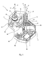
- the invention relates to an electric actuator 1 for moving optical elements, as illustrated in FIG. figure 1 .
- Such an electric actuator 1 comprises a housing 2 (only a lower half of which is shown in FIG. figure 1 ).
- the housing 2 comprises a bottom plate 28, and a peripheral wall 27.
- the electric actuator 1 also comprises an electric motor 3, a mechanical transmission assembly 10 and a drive means 20.
- the mechanical transmission assembly 10 is arranged to transmit a movement of the electric motor 3 to the drive means 20.
- the latter is configured to be connected to an optical element not shown and transmit a movement of the motor.
- the motor 3 here drives the mechanical transmission assembly 10 via a shaft of the motor rotated about an axis B.
- mobile optical element any optical element of a vehicle headlight, in particular automobile, being movable, for example in order to change the shape and / or direction of the light beam emitted by the lighthouse, including the lighthouse itself.
- the mechanical transmission assembly 10 comprises a first gear 11 comprising here two toothed wheels 12, 13, said first and second gear wheels 12, 13.
- the first gear 12 is in particular located at the output of the motor 3, that is, to say that it is located in the extension of the motor shaft.
- the first gear 11 makes it possible to multiply the movement of the electric motor 3, for example by 3. It is understood here that when the electric motor 3 makes three revolutions, the first gear 12 makes three turns and the second gear 13 makes one.
- the mechanical transmission assembly 10 also comprises a worm 15.
- the worm 15 is rotatably connected to the first gear 11. It rotates around an axis of rotation A coinciding with the axis of rotation of the spindle.
- second gear 13 The axis of rotation A is parallel to the axis of rotation B of the first gear 12.
- the worm is thus free to rotate about its axis of rotation A. It is mounted on a support.
- the support here comprises a plate 30 extending in particular against the motor 3 perpendicularly to the motor shaft and a stop 26 protruding from the side walls 27 of the housing 2.
- the support forms an integral part of the housing 2.
- the mechanical transmission assembly 10 further comprises a toothed sector 16.
- the toothed sector 16 transmits the movement of the worm 15 to the drive means 20. It is rotatably mounted relative to the housing 2 along an axis of rotation C. The axis of rotation of the drive means 20 coincides with that of the toothed sector 16.
- radial, transverse and axial clearance of the worm is understood to mean the radial, transverse and axial clearance of the worm relative to its support, that is to say the clearance between the screw endless 15 and its support.
- the electric actuator 1 comprises a return means 25 exerting an axial pressure on the worm 15 so as to press against it its support.
- the return means 25 clamps the worm against the housing 2 and in particular against the plate 30 so as to cancel the axial play of the worm 15.
- axial play is meant the clearance in a defined axial direction by the motor shaft, that is to say the play in a direction parallel to the axis of rotation A.
- the only axial movement of the transmission assembly capable of rotating the driving means 20 is that of the worm, the invention thus makes it possible to cancel all the axial clearances having an influence on the angular position of the driving medium 20.
- the return means 25 also exerts a transverse force on the worm 15, that is to say a force directed in a direction transverse to that of the axis of rotation of the worm, so as to press the endless screw against its support. No transverse movement of the worm is possible and no transverse movement of the worm will cause rotation of the drive means 20.
- the return means 25 is in particular located on the drive means.
- the return means 25 plates the sector toothed 16 on the worm 15 in an axial direction and for example transverse.
- the return means 25 is here a torsion spring. It exerts on the toothed sector 16 a radial force around the axis of rotation C, in the direction of clockwise relative to the orientation of the axis C, illustrated by the arrow referenced D.
- the means of reminder 25 thus plate teeth sector toothed 16 against the worm 15 so as to exert the axial and transverse pressures on the worm 15 mentioned above.
- the return means 25 exerting axial pressure against the worm 15 constrains the rotation of the worm in a first radial direction illustrated here by the arrow E and corresponding to a rotation about the axis of rotation A in the direction of clockwise relative to the orientation of the axis of rotation A. Indeed, to rotate in this direction, the worm must push against the return means in the opposite direction to the axial force.
- the axial pressure exerted on the worm 15 by the return means 25 creates a stress between the worm 15 and its support, in particular between the worm 15 and the plate 30 so that the rotation of the worm 15 the worm in both directions of rotation is constrained.
- the worm 15 is pinched axially by the return means 25 against the housing 2, in particular at the plate 30, so that its rotation is also locked by friction between the worm 15 and the housing 2 .
- the return means 25 thus radially locks the worm 15 in both directions of rotation about its axis of rotation.
- the biasing means is sized to counter any moment of force applied to the worm 15 which is less than or equal to 1 millinewton per meter.
- the electric actuator also comprises a motor control system 50 comprising a connector 55 and an electronic card 60.
- the position sensor 70 is connected to the electronic card 60 in order to transmit the position of the drive means 20.
- the control system 50 thanks to the information received by the position sensor 70, can then actuate the motor to correct a possible positioning error.
Landscapes
- Engineering & Computer Science (AREA)
- General Engineering & Computer Science (AREA)
- Mechanical Engineering (AREA)
- Gear Transmission (AREA)
- Transmission Devices (AREA)
- Lens Barrels (AREA)
Applications Claiming Priority (1)
| Application Number | Priority Date | Filing Date | Title |
|---|---|---|---|
| FR1457094A FR3024085B1 (fr) | 2014-07-23 | 2014-07-23 | Actionneur pour rendre au moins un element optique mobile |
Publications (2)
| Publication Number | Publication Date |
|---|---|
| EP2977262A2 true EP2977262A2 (de) | 2016-01-27 |
| EP2977262A3 EP2977262A3 (de) | 2016-04-20 |
Family
ID=51987242
Family Applications (1)
| Application Number | Title | Priority Date | Filing Date |
|---|---|---|---|
| EP15176825.6A Withdrawn EP2977262A3 (de) | 2014-07-23 | 2015-07-15 | Stellglied zum wiedergeben mindestens eines mobilen optischen elements |
Country Status (4)
| Country | Link |
|---|---|
| US (1) | US10323734B2 (de) |
| EP (1) | EP2977262A3 (de) |
| CN (1) | CN105305717B (de) |
| FR (1) | FR3024085B1 (de) |
Families Citing this family (1)
| Publication number | Priority date | Publication date | Assignee | Title |
|---|---|---|---|---|
| CN110220159B (zh) * | 2018-03-02 | 2025-03-28 | 法雷奥市光(中国)车灯有限公司 | 照明和/或信号指示装置以及机动车辆 |
Citations (1)
| Publication number | Priority date | Publication date | Assignee | Title |
|---|---|---|---|---|
| US5605071A (en) * | 1995-06-06 | 1997-02-25 | Itt Automotive Electrical Systems, Inc. | Enveloped worm gear clutch wedgelock responsive to reaction force |
Family Cites Families (9)
| Publication number | Priority date | Publication date | Assignee | Title |
|---|---|---|---|---|
| IT950189B (it) * | 1972-03-15 | 1973-06-20 | Magneti Marelli Spa | Dispositivo per guidare e per ri prendere il gioco assiale delle viti dei riduttori a vite senza fine particolarmente per motori duttori di piccola potenza |
| FR2568525B1 (fr) * | 1984-08-01 | 1987-01-30 | Manzoni Stephane | Dispositif de reglage de la position de projecteurs de vehicules |
| FR2771469B1 (fr) * | 1997-11-27 | 2000-02-04 | Meritor Light Vehicle Sys Ltd | Motoreducteur pour l'entrainement d'equipements de vehicules tel que leve-vitre avec suppression du jeu axial de sa ligne d'arbre |
| FR2814717B1 (fr) * | 2000-10-04 | 2003-02-28 | Papeteries Matussiere Forest | Appareil pour la pose automatique de liens torsades |
| EP1431118A3 (de) * | 2002-12-17 | 2010-03-17 | Saia-Burgess Murten AG | Aktuator für Scheinwerfer |
| DE10259957A1 (de) * | 2002-12-20 | 2004-07-15 | Robert Bosch Gmbh | Getriebe-Antriebseinheit |
| EP2446020A4 (de) * | 2009-06-25 | 2013-08-14 | Univ Columbia | Neuprogrammierung dentaler stammzellen |
| TW201336713A (zh) * | 2012-03-02 | 2013-09-16 | Tricore Corp | 利用齒輪傳動之車燈轉向驅動裝置 |
| TWM446118U (zh) * | 2012-09-05 | 2013-02-01 | Tricore Corp | 車燈角度調整機構 |
-
2014
- 2014-07-23 FR FR1457094A patent/FR3024085B1/fr not_active Expired - Fee Related
-
2015
- 2015-07-15 EP EP15176825.6A patent/EP2977262A3/de not_active Withdrawn
- 2015-07-22 CN CN201510434980.0A patent/CN105305717B/zh not_active Expired - Fee Related
- 2015-07-23 US US14/807,534 patent/US10323734B2/en active Active
Patent Citations (1)
| Publication number | Priority date | Publication date | Assignee | Title |
|---|---|---|---|---|
| US5605071A (en) * | 1995-06-06 | 1997-02-25 | Itt Automotive Electrical Systems, Inc. | Enveloped worm gear clutch wedgelock responsive to reaction force |
Also Published As
| Publication number | Publication date |
|---|---|
| US10323734B2 (en) | 2019-06-18 |
| CN105305717A (zh) | 2016-02-03 |
| EP2977262A3 (de) | 2016-04-20 |
| FR3024085B1 (fr) | 2018-01-12 |
| US20160025195A1 (en) | 2016-01-28 |
| CN105305717B (zh) | 2020-06-19 |
| FR3024085A1 (fr) | 2016-01-29 |
Similar Documents
| Publication | Publication Date | Title |
|---|---|---|
| WO2018060630A1 (fr) | Motoreducteur présentant un capteur de position entourant la roue de sortie | |
| FR2817212A1 (fr) | Lampe de vehicule et appareil d'entrainement en rotation d'un dispositif optique | |
| FR2894172A1 (fr) | Outillage de vissage a tete d'angle, incluant un capteur de couple monte sur l'arbre de sortie, et module de transmission correspondant. | |
| FR3120843A1 (fr) | Dispositif de changement de vitesse et engin de mobilité associé. | |
| FR2954615A1 (fr) | Moteur electrique notamment pour un entrainement d'essuie-glace et entrainement d'essuie-glace ainsi realise | |
| EP2951464B1 (de) | Vorrichtung zur unterdrückung von lageabweichungen in einem untersetzungsgetriebe mit einem umlaufenden rad | |
| EP2912345B1 (de) | Vorrichtung zur betätigung eines oder mehrerer beweglicher teile, insbesondere für einen kraftfahrzeug-turbolader | |
| EP2577234B1 (de) | Indikator einer instrumententafel mit komplexer planarer bewegung | |
| FR3024085A1 (fr) | Actionneur pour rendre au moins un element optique mobile | |
| FR2859050A1 (fr) | Unite d'entrainement et de transmission comportant au moins deux moteurs pour actionner ou deplacer une piece equipant un vehicule automobile | |
| WO2003025423A1 (fr) | Reducteur a train epicycloïdal notamment pour demarreur de vehicule automobile et demmarreur equipe d'un tel reducteur | |
| EP1820694A2 (de) | Perfektionierte Anordnung zum Schwenken eines elliptischen Moduls eines Beleuchtungssystems für Kraftfahrzeuge | |
| WO2014006306A1 (fr) | Dispositif de captation de la position linéaire d'un organe de transmission sous forme d'un câble, assujetti a un levier d'une boite de commande de vitesses d'un véhicule automobile. | |
| EP4467949A1 (de) | System zur bestimmung eines zwischen zwei rotierenden teilen ausgeübten drehmoments | |
| FR2851539A1 (fr) | Palier d'articulation d'un element de direction | |
| FR2912368A1 (fr) | Ensemble moteur et engrenage reducteur | |
| EP0882986A1 (de) | Vorrichtung zur Bestimmung der Parameter der Rotation einer Lenkwelle | |
| EP4354108B1 (de) | System zur bestimmung eines drehmoments zwischen zwei rotierenden teilen | |
| FR3156423A1 (fr) | Module mécatronique d’assistance électrique | |
| EP4381208B1 (de) | Aktuator zur betätigung mindestens eines beweglichen glieds eines fahrzeugantriebsstrangs | |
| FR3145590A1 (fr) | Actionneur électromécanique | |
| WO2020001903A1 (fr) | Moto-reducteur, systeme d'essuyage et procede de commande associes | |
| WO2025248045A1 (fr) | Module de transmission d'une rotation | |
| FR2975646A1 (fr) | Projecteur pour vehicule automobile | |
| FR3145589A1 (fr) | Actionneur électromécanique |
Legal Events
| Date | Code | Title | Description |
|---|---|---|---|
| PUAI | Public reference made under article 153(3) epc to a published international application that has entered the european phase |
Free format text: ORIGINAL CODE: 0009012 |
|
| AK | Designated contracting states |
Kind code of ref document: A2 Designated state(s): AL AT BE BG CH CY CZ DE DK EE ES FI FR GB GR HR HU IE IS IT LI LT LU LV MC MK MT NL NO PL PT RO RS SE SI SK SM TR |
|
| AX | Request for extension of the european patent |
Extension state: BA ME |
|
| PUAL | Search report despatched |
Free format text: ORIGINAL CODE: 0009013 |
|
| AK | Designated contracting states |
Kind code of ref document: A3 Designated state(s): AL AT BE BG CH CY CZ DE DK EE ES FI FR GB GR HR HU IE IS IT LI LT LU LV MC MK MT NL NO PL PT RO RS SE SI SK SM TR |
|
| AX | Request for extension of the european patent |
Extension state: BA ME |
|
| RIC1 | Information provided on ipc code assigned before grant |
Ipc: F16H 55/24 20060101ALI20160316BHEP Ipc: F16H 57/12 20060101ALI20160316BHEP Ipc: B60Q 1/076 20060101AFI20160316BHEP |
|
| 17P | Request for examination filed |
Effective date: 20160908 |
|
| RBV | Designated contracting states (corrected) |
Designated state(s): AL AT BE BG CH CY CZ DE DK EE ES FI FR GB GR HR HU IE IS IT LI LT LU LV MC MK MT NL NO PL PT RO RS SE SI SK SM TR |
|
| STAA | Information on the status of an ep patent application or granted ep patent |
Free format text: STATUS: EXAMINATION IS IN PROGRESS |
|
| 17Q | First examination report despatched |
Effective date: 20220517 |
|
| RIC1 | Information provided on ipc code assigned before grant |
Ipc: F16H 57/021 20120101ALN20230509BHEP Ipc: F16H 57/12 20060101ALI20230509BHEP Ipc: F16H 55/24 20060101ALI20230509BHEP Ipc: B60Q 1/076 20060101AFI20230509BHEP |
|
| GRAP | Despatch of communication of intention to grant a patent |
Free format text: ORIGINAL CODE: EPIDOSNIGR1 |
|
| STAA | Information on the status of an ep patent application or granted ep patent |
Free format text: STATUS: GRANT OF PATENT IS INTENDED |
|
| RIC1 | Information provided on ipc code assigned before grant |
Ipc: F16H 57/021 20120101ALN20230530BHEP Ipc: F16H 57/12 20060101ALI20230530BHEP Ipc: F16H 55/24 20060101ALI20230530BHEP Ipc: B60Q 1/076 20060101AFI20230530BHEP |
|
| INTG | Intention to grant announced |
Effective date: 20230626 |
|
| P01 | Opt-out of the competence of the unified patent court (upc) registered |
Effective date: 20230628 |
|
| STAA | Information on the status of an ep patent application or granted ep patent |
Free format text: STATUS: THE APPLICATION IS DEEMED TO BE WITHDRAWN |
|
| 18D | Application deemed to be withdrawn |
Effective date: 20231107 |