EP2977281A1 - Bremssteuerungsvorrichtung und sattelfahrzeug damit - Google Patents
Bremssteuerungsvorrichtung und sattelfahrzeug damit Download PDFInfo
- Publication number
- EP2977281A1 EP2977281A1 EP14768740.4A EP14768740A EP2977281A1 EP 2977281 A1 EP2977281 A1 EP 2977281A1 EP 14768740 A EP14768740 A EP 14768740A EP 2977281 A1 EP2977281 A1 EP 2977281A1
- Authority
- EP
- European Patent Office
- Prior art keywords
- wheel
- brake
- lateral sliding
- slip ratio
- lateral
- Prior art date
- Legal status (The legal status is an assumption and is not a legal conclusion. Google has not performed a legal analysis and makes no representation as to the accuracy of the status listed.)
- Granted
Links
Images








Classifications
-
- B—PERFORMING OPERATIONS; TRANSPORTING
- B60—VEHICLES IN GENERAL
- B60T—VEHICLE BRAKE CONTROL SYSTEMS OR PARTS THEREOF; BRAKE CONTROL SYSTEMS OR PARTS THEREOF, IN GENERAL; ARRANGEMENT OF BRAKING ELEMENTS ON VEHICLES IN GENERAL; PORTABLE DEVICES FOR PREVENTING UNWANTED MOVEMENT OF VEHICLES; VEHICLE MODIFICATIONS TO FACILITATE COOLING OF BRAKES
- B60T8/00—Arrangements for adjusting wheel-braking force to meet varying vehicular or ground-surface conditions, e.g. limiting or varying distribution of braking force
- B60T8/17—Using electrical or electronic regulation means to control braking
- B60T8/1701—Braking or traction control means specially adapted for particular types of vehicles
- B60T8/1706—Braking or traction control means specially adapted for particular types of vehicles for single-track vehicles, e.g. motorcycles
-
- B—PERFORMING OPERATIONS; TRANSPORTING
- B60—VEHICLES IN GENERAL
- B60T—VEHICLE BRAKE CONTROL SYSTEMS OR PARTS THEREOF; BRAKE CONTROL SYSTEMS OR PARTS THEREOF, IN GENERAL; ARRANGEMENT OF BRAKING ELEMENTS ON VEHICLES IN GENERAL; PORTABLE DEVICES FOR PREVENTING UNWANTED MOVEMENT OF VEHICLES; VEHICLE MODIFICATIONS TO FACILITATE COOLING OF BRAKES
- B60T2230/00—Monitoring, detecting special vehicle behaviour; Counteracting thereof
- B60T2230/02—Side slip angle, attitude angle, floating angle, drift angle
Definitions
- the present invention relates to a brake control device that adjusts brake force supplied to a wheel, and a straddled vehicle including the brake control device.
- ABS Antilock Brake System
- An ABS prevents slip at a time of sudden braking and enables a brake distance of a vehicle to be shortened and a handle operation at a time of braking by automatically controlling a rotation of a wheel.
- the ABS is provided in not limited to four-wheeled automobiles but various vehicles such as a motorcycle.
- lateral force is generated between the wheel and a road surface.
- lateral sliding of the vehicle occurs.
- the motorcycle tilts in a lateral direction during the turning.
- a yaw rate measured by a yaw rate sensor is integrated over time, so that the tilt angle (the bank angle) of a motorcycle in the lateral direction is determined.
- a sliding threshold value used for an antilock brake operation is set such that the larger the tilt angle of the motorcycle is, the smaller the sliding threshold value is. In this case, a brake effect quickly decreases when the tilt angle of the motorcycle increases.
- a target slip ratio used for the antilock brake operation is set such that the larger the bank angle of a motorcycle is, the smaller the target slip ratio is. In this case, the target slip ratio is inhibited as the bank angle increases.
- an effective limit value used for the antilock brake operation (a value for starting to decrease a brake pressure at the time of braking) changes in response to a result of measurement of a tilt position of an auto-bicycle.
- the effective limit value of the ABS is set small as the tilt of the auto-bicycle increases. In this case, the brake pressure is gradually decreased before the tilt of the auto-bicycle in the lateral direction becomes larger.
- a tilt posture angle of a motorcycle is calculated.
- the brake pressure of the front wheel is maintained by an adjuster of the antilock brake system before reaching a lock pressure to be expected.
- An object of the present invention is to provide a brake control device that enables a brake operation of a straddled vehicle to be smoothly and easily performed, and a straddled vehicle including the brake control device.
- the longitudinal sliding degree of the first wheel is detected by the longitudinal sliding detection device, and the lateral sliding degree of the first wheel is detected by the lateral sliding detection device.
- the first antilock brake operation is performed by the controller at the time of braking of the first wheel.
- the first brake device is controlled such that the detected longitudinal sliding degree of the first wheel becomes close to the first target longitudinal sliding degree.
- the first correction process is performed.
- the first antilock brake operation is corrected such that the lateral sliding of the first wheel is inhibited based on the result of detection of the lateral sliding detection device.
- the lateral sliding degree of the first wheel When the lateral sliding degree of the first wheel is large, an amount of correction in the first correction process is increased, so that the lateral sliding of the first wheel can be inhibited while the brake force for the first wheel is ensured. Further, when the lateral sliding degree of the first wheel is small, the amount of correction in the first correction process is decreased, so that the brake force for the first wheel can be sufficiently ensured while the lateral sliding of the first wheel is inhibited. Further, the lateral sliding is unlikely to occur at the time of braking during the travelling of the vehicle in a straight line. In this case, the amount of correction in the first correction process is decreased, so that sufficient deceleration can be performed at the time of braking during the travelling of the vehicle in the straight line.
- the lateral sliding of the first wheel can be inhibited regardless of the tilt state of the vehicle and the states of the road surface and the first wheel, and the brake force for the first wheel can be ensured.
- the rider can smoothly and easily perform the brake operation of the straddled vehicle.
- the controller may correct the first antilock brake operation such that the larger the lateral sliding degree of the first wheel detected by the lateral sliding detection device is, the smaller the longitudinal sliding degree of the first wheel is, as the first correction process.
- the lateral sliding detection device may detect lateral sliding acceleration of the first wheel as the lateral sliding degree of the first wheel, and the controller may correct the first antilock brake operation by changing the first target longitudinal sliding degree such that the larger magnitude of the lateral sliding acceleration of the first wheel detected by the lateral sliding detection device is, the smaller the first target longitudinal sliding degree is, as the first correction process.
- the first target longitudinal sliding degree is small, so that the margin of the maximum lateral force that can be generated between the first wheel and the road surface with respect to the lateral force required in order to prevent the lateral sliding of the first wheel increases.
- the lateral sliding of the first wheel can be inhibited while the brake force for the first wheel is ensured.
- the first target longitudinal sliding degree is large, so that an amount of decrease of the brake force for the first wheel is small.
- the brake force for the first wheel can be ensured while the lateral sliding of the first wheel is inhibited.
- the lateral sliding is unlikely to occur.
- the first target longitudinal sliding degree increases, so that the amount of decrease of the brake force for the first wheel is small.
- sufficient deceleration is performed at the time of braking during the travelling of the vehicle in the straight line.
- the lateral sliding of the first wheel can be inhibited regardless of the tilt state of the vehicle and the states of the road surface and the first wheel, and the brake force for the first wheel can be ensured.
- the magnitude of the lateral sliding acceleration of the first wheel is equivalent to the insufficiency of the lateral force required in order to prevent an occurrence of the lateral sliding of the first wheel, and the lateral sliding occurs due to this insufficiency. Therefore, the lateral sliding degree can be accurately detected based on the magnitude of the lateral sliding acceleration of the first wheel. Therefore, the first target longitudinal sliding degree can be accurately changed such that the margin of the maximum lateral force and the brake force are ensured based on the magnitude of the lateral sliding acceleration of the first wheel. Thus, the lateral sliding of the first wheel can be appropriately inhibited.
- the controller may change the first target longitudinal sliding degree such that the first target longitudinal sliding degree decreases from a third value to a fourth value smaller than the third value as the magnitude of the lateral sliding acceleration of the first wheel detected by the lateral sliding detection device increases, when the magnitude of the lateral sliding acceleration of the first wheel detected by the lateral sliding detection device is in a range between a first value and a second value larger than the first value.
- the lateral sliding acceleration of the first wheel when the lateral sliding acceleration of the first wheel is in a constant range, the larger the magnitude of the lateral sliding acceleration of the first wheel is, the lower the first target longitudinal sliding degree is.
- the lateral sliding of the first wheel can be appropriately inhibited while the brake force for the first wheel is ensured.
- the controller may set the first target longitudinal sliding degree to the third value when the magnitude of the lateral sliding acceleration of the first wheel detected by the lateral sliding detection device is not more than the first value.
- the first target longitudinal sliding degree is kept constant at the third value.
- the controller may set the first target longitudinal sliding degree to the fourth value when the magnitude of the lateral sliding acceleration of the first wheel detected by the lateral sliding detection device is not less than the second value.
- the first target longitudinal sliding degree is kept constant at the fourth value.
- the brake control device may further include a storage that stores a correspondence relationship between the magnitude of the lateral sliding acceleration of the first wheel and a target longitudinal sliding degree, wherein the correspondence relationship may be set in advance such that the target longitudinal sliding degree decreases from the third value to the fourth value as the magnitude of the lateral sliding acceleration of the first wheel increases, and the controller may acquire the target longitudinal sliding degree corresponding to the magnitude of the lateral sliding acceleration of the first wheel detected by the lateral sliding detection device from the first correspondence relationship stored in the first storage, and may set the acquired target longitudinal sliding degree as the first target longitudinal sliding degree as the first correction process.
- the first target longitudinal sliding degree corresponding to the lateral sliding acceleration of the first wheel can be easily set without a calculation process.
- the lateral sliding detection device may detect a slip angle of the first wheel as the lateral sliding degree of the first wheel, and the controller may correct the first antilock brake operation by changing the first target longitudinal sliding degree such that the larger magnitude of the slip angle of the first wheel detected by the lateral sliding detection device is, the smaller the first target longitudinal sliding degree is, as the first correction process.
- the first target longitudinal sliding degree can be accurately changed such that the margin of the maximum lateral force and the brake force are ensured based on the magnitude of the slip angle of the first wheel.
- the lateral sliding of the first wheel can be appropriately inhibited.
- the straddled vehicle may further have a second wheel, and may further comprise a second brake device that supplies the brake force to the second wheel, the longitudinal sliding detection device may be configured to detect a longitudinal sliding degree of the second wheel, the lateral sliding detection device may be configured to detect a lateral sliding degree of the second wheel, and the controller may perform a second antilock brake operation for controlling the second brake device such that the longitudinal sliding degree of the second wheel detected by the longitudinal sliding detection device becomes close to a second target longitudinal sliding degree, and may perform a second correction process for correcting the second antilock brake operation by changing the second target longitudinal sliding degree such that the larger the lateral sliding degree of the second wheel detected by the lateral sliding detection device is, the smaller the second target longitudinal sliding degree is.
- the second antilock brake operation is performed by the controller at the time of braking of the second wheel, and the second correction process is performed.
- the second target longitudinal sliding degree is changed such that the larger the lateral sliding degree of the second wheel detected by the lateral sliding detection device is, the smaller the second target longitudinal sliding degree is.
- the controller may increase the brake force by the second brake device to compensate at least part of an amount of decrease of the brake force by the first brake device, the amount of decrease being generated by performance of the first correction process, when the first antilock brake operation is performed and the second antilock brake operation is not performed.
- the decrease of the brake force for the first wheel by the performance of the first correction process is compensated by the increase of the brake force for the second wheel.
- the decrease of the brake force exerted on the entire straddled vehicle can be inhibited.
- the controller may increase the brake force by the first brake device to compensate at least part of an amount of decrease of the brake force by the second brake device, the amount of decrease being generated by performance of the second correction process, when the second antilock brake operation is performed and the first antilock brake operation is not performed.
- the decrease of the brake force for the second wheel by the performance of the second correction process is compensated by the increase of the brake force for the first wheel.
- the decrease of the brake force exerted on the entire straddled vehicle can be inhibited.
- the longitudinal sliding detection device may be configured to detect a slip ratio of the first wheel as the longitudinal sliding degree of the first wheel, and the controller may perform the first antilock brake operation by controlling the first brake device such that the slip ratio of the first wheel detected by the longitudinal sliding detection device becomes close to a first target slip ratio as the first target longitudinal sliding degree, and may correct the first antilock brake operation by changing the first target slip ratio such that the larger the lateral sliding degree of the first wheel detected by the lateral sliding detection device is, the smaller the first target slip ratio is, as the first correction process.
- the slip ratio of the wheel can be calculated by a simple calculation formula based on the peripheral velocity of the wheel and the vehicle body velocity. Therefore, it is possible to easily perform the first antilock brake operation without providing the complicated configuration and performing the complicated process, and the first correction process can be easily performed.
- the longitudinal sliding detection device may be configured to detect slip ratios of the respective first and second wheels as the respective longitudinal sliding degrees of the first and second wheels, and the controller may perform the first antilock brake operation by controlling the first brake device such that the slip ratio of the first wheel detected by the longitudinal sliding detection device becomes close to a first target slip ratio as the first target longitudinal sliding degree, may perform the second antilock brake operation by controlling the second brake device such that the slip ratio of the second wheel detected by the longitudinal sliding detection device becomes close to a second target slip ratio as the second target longitudinal sliding degree, may correct the first antilock brake operation by changing the first target slip ratio such that the larger the lateral sliding degree of the first wheel detected by the lateral sliding detection device is, the smaller the first target slip ratio is, as the first correction process, and may correct the second antilock brake operation by changing the second target slip ratio such that the larger the lateral sliding degree of the second wheel detected by the lateral sliding detection device is, the smaller the second target slip ratio is, as the second correction process.
- the slip ratio of the wheel can be calculated by a simple calculation formula based on the peripheral velocity of the wheel and the vehicle body velocity. Therefore, it is possible to easily perform the first and second antilock brake operations without providing the complicated configuration and performing the complicated process, and the first and second correction processes can be easily performed.
- a straddled vehicle includes the first wheel, and the above-mentioned brake control device.
- the first antilock brake operation is corrected based on the lateral sliding degree of the first wheel.
- the lateral sliding of the first wheel is inhibited regardless of the tilt state of the vehicle and the states of the road surface and the first wheel, and the brake force for the first wheel is ensured.
- sufficient deceleration is performed at the time of braking during the traveling of the vehicle in a straight line. As a result, the rider can smoothly and easily perform the brake operation of the straddled vehicle.
- a straddled vehicle includes the first and second wheels, and the above-mentioned brake control device.
- the first and second antilock brake operations are corrected based on the lateral sliding degrees of the first and second wheels.
- the lateral sliding of the first and second wheels is inhibited regardless of the tilt state of the vehicle and the states of the road surface and the first and second wheels, and the brake force for the first and second wheels is ensured. Further, sufficient deceleration is performed at the time of braking during the travelling of the vehicle in a straight line.
- the present invention enables the brake operation of the straddled vehicle to be smoothly and easily performed.
- a brake control device and a straddled vehicle including the brake control device according to the first embodiment will be described with reference to drawings.
- a motorcycle including the brake control device will be described as one example of the straddled vehicle.
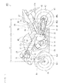
- Fig. 1 is a schematic side view of the motorcycle according to one embodiment of the present invention as viewed from the left.
- a head pipe 12 is provided at the front end of a main body frame 11.
- a front fork 13 is provided at the head pipe 12 to be swingable in a left-and-right direction.
- a front wheel 14 and a brake rotor BR1 are rotatably supported at the lower end of the front fork 13. Further, a wheel cylinder WC1 and a front wheel velocity sensor 44 are fixed to a portion in the vicinity of the lower end of the front fork 13.
- the brake rotor BR1 includes one or plurality of discs (not shown).
- the wheel cylinder WC1 is incorporated in a brake caliper together with a brake pad (not shown) pressed against the disc of the brake rotor BR1 at a time of braking of the front wheel 14.
- the front wheel velocity sensor 44 detects a rotation velocity of the front wheel 14 and supplies a result of detection to a lateral sliding acceleration detection device 50, an ECU for ABS (Electronic Control Unit for Antilock Brake System) 60, and an ECU (Electronic Control Unit) 70, described below.
- a handle 15 is provided at the upper end of the head pipe 12.
- Fig. 2 is a schematic plan view of the motorcycle 100 of Fig. 1 as viewed from above.
- constituent elements of part of the motorcycle 100 are shown together with an outer shape of the motorcycle 100 of Fig. 1 .
- a brake lever 16 and a front wheel master cylinder 16s are provided at a right side portion of the handle 15.
- an engine 17 is provided at a central portion of the main body frame 11.
- One end of an intake pipe 17a is attached to an intake port of the engine 17.
- One end of an exhaust pipe 17b is attached to an exhaust port of the engine 17.
- a muffler 17c is attached to the other end of the exhaust pipe 17b.
- a crank case 18 is attached to a lower portion of the engine 17.
- a mission case 19 is coupled to a rear portion of the crank case 18. The mission case 19 is positioned at a lower portion of the main body frame 11.
- a shift pedal 21 is provided at a left side portion of the mission case 19.
- a back step 22 is provided behind the shift pedal 21.
- the back step 22 is supported by the main body frame 11.
- a brake pedal 23 and a rear wheel master cylinder 23s are provided at a right side portion of the mission case 19.
- a back step 24 is provided behind the brake pedal 23.
- the back step 24 is supported by the main body frame 11 of Fig. 1 .
- a rear arm 81 is connected to the main body frame 11 to extend rearward of the mission case 19.
- a rear wheel 82, a rear wheel driven sprocket 83 and a brake rotor BR2 are rotatably supported at the rear end of the rear arm 81.
- a chain 84 is attached to the rear wheel driven sprocket 83.
- a wheel cylinder WC2 and a rear wheel velocity sensor 45 are fixed to a portion in the vicinity of the rear end of the rear arm 81.
- the brake rotor BR2 includes one or plurality of discs (not shown).
- a wheel cylinder WC2 is incorporated in a brake caliper together with a brake pad (not shown) pressed against the disc of the brake rotor BR2 at a time of braking of the rear wheel 82.
- the rear wheel velocity sensor 45 detects a rotation velocity of the rear wheel 82, and supplies a result of detection to a lateral sliding acceleration detection device 50, the ECU 60 for ABS and the ECU 70, described below.
- a fuel tank 25 is provided at an upper portion of the engine 17, and two seats 26, 27 are provided behind the fuel tank 25 to be arranged in a front-and-rear direction.
- a fluid pressure control unit 30, a gyroscope 41, a lateral acceleration sensor 42, a longitudinal acceleration sensor 43, the lateral sliding acceleration detection device 50, the ECU 60 for ABS and the ECU 70 are provided at lower portions of the fuel tank 25 and the two seats 26, 27.
- the fluid pressure control unit 30 is connected to the front wheel master cylinder 16s, the rear wheel master cylinder 23s and the wheel cylinders WC1, WC2. Details of the fluid pressure control unit 30 will be described below.
- the gyroscope 41 detects a yaw rate and a roll rate of the motorcycle 100 and supplies results of detection to the lateral sliding acceleration detection device 50, the ECU 60 for ABS and the ECU 70.
- the lateral acceleration sensor 42 detects lateral acceleration generated in the left-and-right direction of the motorcycle 100 and supplies a result of detection to the lateral sliding acceleration detection device 50, the ECU 60 for ABS and the ECU 70.
- the longitudinal acceleration sensor 43 detects longitudinal acceleration generated in the front-and-rear direction of the motorcycle 100 and supplies a result of detection to the lateral sliding acceleration detection device 50, the ECU 60 for ABS and the ECU 70.
- the lateral sliding acceleration detection device 50 is constituted by a CPU (Central Processing Unit) and a memory, or a microcomputer.
- the lateral sliding acceleration detection device 50 detects lateral sliding acceleration as one example of a degree of lateral sliding that occurs in the left-and-right direction of the motorcycle 100 based on the results of detection from the gyroscope 41, the lateral acceleration sensor 42, the longitudinal acceleration sensor 43, the front wheel velocity sensor 44 and the rear wheel velocity sensor 45. Further, the lateral sliding acceleration detection device 50 supplies a result of detection to the ECU 60 for ABS. Details of the lateral sliding acceleration detection device 50 and the definition of the lateral sliding acceleration will be described below.
- the ECU 60 for ABS includes a CPU (Central Processing Unit) 61, a ROM (Read Only Memory) 62, a RAM (Random Access Memory) 63 and an interface circuit 64 as shown in Fig. 3 , described below.
- the CPU 61 controls the fluid pressure control unit 30 based on the results of detection supplied from the gyroscope 41, the lateral acceleration sensor 42, the longitudinal acceleration sensor 43, the front wheel velocity sensor 44, the rear wheel velocity sensor 45 and the lateral sliding acceleration detection device 50 as described below.
- the ROM 62 stores an ABS control program, a target slip ratio table and the like, describe below.
- the RAM 63 stores an ABS flag and various data, described below, and functions as a processing area of the CPU 61.
- the ECU 70 includes the CPU, the ROM, the RAM and the interface circuit that are not shown. Results of detection are supplied to the CPU of the ECU 70 from various sensors.
- the CPU of the ECU 70 controls operations of the engine 17, a transmission (not shown) and the like based on these results of detection.
- the ROM of the ECU 70 stores a control program of the CPU of the ECU 70 and the like.
- the RAM of the ECU 70 stores various data and functions as a processing area of the CPU of the ECU 70.
- the brake control device is constituted by the brake lever 16, the front wheel master cylinder 16s, the brake pedal 23, the rear wheel master cylinder 23s, the fluid pressure control unit 30, the gyroscope 41, the lateral acceleration sensor 42, the longitudinal acceleration sensor 43, the rear wheel velocity sensor 45, the lateral sliding acceleration detection device 50, the ECU 60 for ABS, the wheel cylinders WC1, WC2, the brake rotors BR1, BR2, described above, and brake hoses L1 to L4.
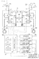
- Fig. 3 is a block diagram showing a configuration of the brake control device included in the motorcycle 100 of Fig. 1 .
- the fluid pressure control unit 30 of Fig. 3 includes a front wheel fluid pressure circuit 30A, a rear wheel fluid pressure circuit 30B, a motor 30C and first to fourth ports p1 to p4.
- the brake hose L1 connects the first port p1 of the fluid pressure control unit 30 and the front wheel master cylinder 16s, and the brake hose L2 connects the second port p2 and the wheel cylinder WC1 of the front wheel 14.
- the brake hose L3 connects the third port p3 of the fluid pressure control unit 30 and the rear wheel master cylinder 23s, and the brake hose L4 connects the fourth port p4 and the wheel cylinder WC2 of the rear wheel 82.
- the front wheel fluid pressure circuit 30A mainly includes a holding valve 31a, a pressure reducing valve 32a, a pump 33a and a reservoir 34a and is provided between the first port p1 and the second port p2.
- the front wheel fluid pressure circuit 30A connects the front wheel master cylinder 16s and the wheel cylinder WC1 of the front wheel 14 via the brake hoses L1, L2.
- the holding valve 31a is provided between the first port p1 and the second port p2, and the pressure reducing valve 32a is provided between the second port p2 and the reservoir 34a.
- Each of the holding valve 31a and the pressure reducing valve 32a is a two-position switching-type electromagnetic valve having two ports.
- the pump 33a is provided between the first port p1 and the reservoir 34a. An inlet port of the pump 33a is connected to the reservoir 34a, and a discharge port of the pump 33a is connected to the first port p1.
- a brake fluid is filled in the front wheel master cylinder 16s, the front wheel fluid pressure circuit 30A and the brake hoses L1, L2.
- the rear wheel fluid pressure circuit 30B mainly includes a holding valve 31b, a pressure reducing valve 32b, a pump 33b and a reservoir 34b and is provided between the third port p3 and the fourth port p4.
- the rear wheel fluid pressure circuit 30B connects the rear master cylinder 23s to the wheel cylinder WC2 of the rear wheel 82 via the brake hoses L3, L4.
- the holding valve 31 b is provided between the third port p3 and the fourth port p4, and the pressure reducing valve 32b is provided between the fourth valve p4 and the reservoir 34b.
- Each of the holding valve 31 b and the pressure reducing valve 32b is a two-position switching-type electromagnetic valve having two ports.
- the pump 33b is provided between the third port p3 and the reservoir 34b. An inlet port of the pump 33b is connected to the reservoir 34b, and a discharge port of the pump 30b is connected to the third port p3.
- the brake fluid is filled in the rear wheel master cylinder 23s, the rear wheel fluid pressure circuit 30B and the brake hoses L3, L4.
- the motor 30C is used to respectively drive the pump 33a of the front wheel fluid pressure circuit 30A and the pump 33b of the rear wheel fluid pressure circuit 30B.
- results of detection of the gyroscope 41, the lateral acceleration sensor 42, the longitudinal acceleration sensor 43, the front wheel velocity sensor 44, the rear wheel velocity sensor 45 and the lateral sliding acceleration detection device 50 are supplied to the ECU 60 for ABS.
- the CPU 61 of the ECU 60 for ABS controls the operations of the front wheel fluid pressure circuit 30A, the rear wheel fluid pressure circuit 30B and the motor 30C based on the supplied results of detection.
- a pressure of the brake fluid supplied to each of the wheel cylinders WC1, WC2 (hereinafter referred to as a WC fluid pressure) is adjusted.
- Fig. 4 is a schematic diagram for explaining an adjustment operation of the WC fluid pressure in the front wheel fluid pressure circuit 30A of Fig. 3 .
- a constant fluid pressure is supplied to the front wheel master cylinder 16s by an operation of the brake lever 16.
- FIG. 4(a) A state of the front wheel fluid pressure circuit 30A of when the adjustment of the WC fluid pressure is not performed is shown in Fig. 4(a) .
- the CPU 61 of Fig. 3 opens the holding valve 31a, closes the pressure reducing valve 32a and stops the pump 33a.
- the front wheel master cylinder 16s and the wheel cylinder WC1 communicate with each other via the holding valve 31 a. Therefore, the fluid pressure supplied to the front wheel master cylinder 16s by the operation of the brake lever 16 is transmitted to the wheel cylinder WC1.
- FIG. 4(b) A state of the front wheel fluid pressure circuit 30A of when the WC fluid pressure is adjusted to decrease is shown in Fig. 4(b) .
- the CPU 61 of Fig. 3 closes the holding valve 31a, opens the pressure reducing valve 32a and activates the pump 33a.
- the front wheel master cylinder 16s and the reservoir 34a communicate with each other.
- the pump 33a draws up the brake fluid in the reservoir 34a towards the first port p1. Therefore, the brake fluid in the wheel cylinder WC1 flows in the reservoir 34a.
- the WC fluid pressure decreases regardless of the operation of the brake lever 16.
- FIG. 4(c) A state of the front wheel fluid pressure circuit 30A of when the WC fluid pressure is adjusted to increase is shown in Fig. 4(c) .
- the CPU 61 of Fig. 3 opens the holding valve 31a, closes the pressure reducing valve 32a and activates the pump 33a.
- the front wheel master cylinder 16s and the reservoir 34a communicate with each other.
- the pump 33a draws up the brake fluid in the reservoir 34a towards the first port p1. Therefore, the fluid pressure supplied to the front wheel master cylinder 16s is transmitted to the wheel cylinder WC1 by the operation of the brake lever 16, and the brake fluid in the reservoir 34a flows towards the wheel cylinder WC1.
- the WC fluid pressure increases as compared to a case in which the adjustment of the WC fluid pressure is not performed.
- An adjustment operation of the WC fluid pressure in the rear wheel fluid pressure circuit 30B of Fig. 3 is similarly performed to the adjustment operation of the WC fluid pressure in the front wheel fluid pressure circuit 30A.
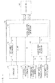
- Fig. 5 is a block diagram for explaining a configuration and an operation of the lateral sliding acceleration detection device 50 of Fig. 3 .
- the lateral sliding acceleration detection device 50 includes a tilt angle calculator 51, a vehicle body velocity calculator 52 and a lateral sliding acceleration calculator 53.
- the tilt angle calculator 51, the vehicle body velocity calculator 52 and the lateral sliding acceleration calculator 53 of Fig. 5 are respectively configured by application programs. Part or all of these constituent elements may be configured by electronic circuits such as logic circuits.
- the roll rate wr detected by the gyroscope 41 is supplied to the tilt angle calculator 51.
- the tilt angle calculator 51 calculates a roll angle (a bank angle) acquired by integrating the supplied roll rate wr over time as a tilt angle ⁇ of the motorcycle 100 and supplies a result of calculation to the lateral sliding acceleration calculator 53.
- the tilt angle ⁇ indicates a tilt in a lateral direction of the motorcycle 100 with respect to a vertical plane parallel to the front-and-rear direction of the motorcycle 100.
- the longitudinal acceleration Ax detected by the longitudinal acceleration sensor 43 is supplied to the vehicle body velocity calculator 52. Further, the rotation velocity Vf of the front wheel 14 detected by the front wheel velocity sensor 44 and the rotation velocity Vr of the rear wheel 82 detected by the rear wheel velocity sensor 45 are supplied to the vehicle body velocity calculator 52.
- the vehicle body velocity calculator 52 calculates the front wheel peripheral velocity by multiplying the rotation velocity Vf of the front wheel 14 by a circumferential length of the front wheel 14 (a length of an outer periphery of a tire). Further, the vehicle body velocity calculator 52 calculates a rear wheel peripheral velocity by multiplying the rotation velocity Vr of the rear wheel 82 by a circumferential length of the rear wheel 82.
- a brake sensor (not shown) is provided in the motorcycle 100 according to the present embodiment.
- the brake sensor detects amounts of operation of the brake lever 16 and the brake pedal 23 by a rider and supplies the detected amounts of operation to the CPU 61 of Fig. 3 and the vehicle body velocity calculator 52.
- the vehicle body velocity calculator 52 determines whether the brake lever 16 and the brake pedal 23 are respectively operated based on the supplied amounts of operation.
- the vehicle body velocity calculator 52 estimates the vehicle body velocity V of the motorcycle 100 based on the longitudinal acceleration Ax, the front wheel peripheral velocity, the rear wheel peripheral velocity, a state of operation of the brake lever 16 and a state of operation of the brake pedal 23.
- Fig. 6 is a diagram for explaining a method of estimation of the vehicle body velocity V of the motorcycle 100.
- a brake state of the motorcycle 100 caused by the operation of only the brake lever 16 by the rider is shown in Fig. 6(a) .
- brake force is generated between the front wheel 14 and a road surface.
- the brake force is not generated between the rear wheel 62 and the road surface. Therefore, it is considered that the vehicle body velocity V is substantially equal to the rear wheel peripheral velocity. Therefore, the vehicle body velocity calculator 52 supplies the calculated rear wheel peripheral velocity to the lateral sliding acceleration calculator 53 as the vehicle body velocity V.
- FIG. 6(b) A brake state of the motorcycle 100 caused by the operation of only the brake pedal 23 by the rider is shown in Fig. 6(b) .
- the brake force is generated between the rear wheel 82 and the road surface.
- the brake force is not generated between the front wheel 14 and the road surface. Therefore, it is considered that the vehicle body velocity V is substantially equal to the front wheel peripheral velocity. Therefore, the vehicle body velocity calculator 52 supplies the calculated front wheel peripheral velocity to the lateral sliding acceleration calculator 53 as the vehicle body velocity V.
- FIG. 6(c) A brake state of the motorcycle 100 caused by the operations of the brake lever 16 and the brake pedal 23 by the rider is shown in Fig. 6(c) .
- the brake force is generated between the front wheel 14 and the road surface.
- the brake force is generated between the rear wheel 82 and the road surface.
- the vehicle body velocity calculator 52 integrates the longitudinal acceleration Ax supplied from the longitudinal acceleration sensor 43 over time from each of the operation starting time points of brake lever 16 and the brake pedal 23 and supplies each integration value to the lateral sliding acceleration calculator 53 as the vehicle body velocity V.
- the yaw rate ⁇ z and the roll rate wr detected by the gyroscope 41 are supplied to the lateral sliding acceleration calculator 53 of the lateral sliding acceleration detection device 50 in addition to the above-mentioned tilt angle ⁇ and the vehicle body velocity V. Further, the lateral acceleration Ay detected by the lateral acceleration sensor 42 is supplied.
- a horizontal distance If ( Fig. 1 ) between an attachment position of the lateral acceleration sensor 42 and the center of the front wheel 14 and a horizontal distance Ir ( Fig. 1 ) between the attachment position of the lateral acceleration sensor 42 and the center of the rear wheel 82 are stored in advance.
- the lateral sliding acceleration calculator 53 calculates the lateral sliding acceleration of the front wheel 14 and the rear wheel 82 based on the supplied tilt angle ⁇ , vehicle body velocity V, yaw rate ⁇ z , roll rate wr and lateral acceleration Ay, and the above-mentioned horizontal distances If, Ir, and supplies a result of calculation to the ECU 60 for ABS.
- the lateral sliding acceleration of the front wheel 14 and the rear wheel 82 may be estimated using another known method.
- the CPU 61 of Fig. 3 calculates the front wheel peripheral velocity, the rear wheel peripheral velocity and the vehicle body velocity V based on the results of detection supplied from the longitudinal acceleration sensor 43, the front wheel velocity sensor 44 and the rear wheel velocity sensor 45 similarly to the vehicle body velocity calculator 52 of Fig. 5 .
- the CPU 61 calculates a slip ratio SLf as one example of a current degree of the longitudinal sliding of the front wheel 14 by a following formula (3) when the front wheel peripheral velocity is represented by Vwf and calculates a slip ratio SLr as one example of a current degree of the longitudinal sliding of the rear wheel 82 by a following formula (4) when the rear wheel peripheral velocity is represented by Vwr.
- SLf V - Vwf / V ⁇ 100
- SLr V - Vwr / V ⁇ 100
- the CPU 61 controls the front wheel fluid pressure circuit 30A of the fluid pressure control unit 30 such that the slip ratio of the front wheel 14 becomes close to a target slip ratio, and controls the rear wheel fluid pressure circuit 30B of the fluid pressure control unit 30 such that the slip ratio of the rear wheel 82 becomes close to the target slip ratio. In this manner, an antilock brake operation of the front wheel 14 is performed, and an antilock brake operation of the rear wheel 82 is performed, by the CPU 61.
- Fig. 7 is a graph for explaining the basic idea of the first embodiment.
- a relationship between the slip ratio on a road surface having high friction coefficient (a dry asphalt road surface, for example) and each of the brake force and maximum lateral force is shown in Fig. 7(a) .
- the maximum lateral force refers to a maximum value of the lateral force that can be generated between the wheel (the front wheel 14 or the rear wheel 82) and the road surface.
- a relationship between the slip ratio on a road surface having low friction coefficient (a wet asphalt road surface, for example) and each of the brake force and the maximum lateral force is shown in Fig. 7(b) .
- Figs. 7 In the graphs of Figs.
- the ordinate indicates the brake force or the lateral force
- the abscissa indicates the slip ratio.
- the brake force generated between the wheel (the front wheel 14 or the rear wheel 82) and the road surface is indicated by a one-dot dash line.
- the maximum lateral force is indicated by a solid line.
- the brake force on the road surface having the low friction coefficient is smaller than the brake force on the road surface having the high friction coefficient.
- the maximum lateral force on the road surface having the low friction coefficient is smaller than the maximum lateral force on the road surface having the high friction coefficient.
- a subtraction value acquired when "the maximum lateral force that can be generated between the wheel and the road surface at the current slip ratio" is subtracted from “lateral force required in order to prevent the lateral sliding of the wheel” is referred to as a margin of the lateral force.
- the target slip ratio is set smaller than the current slip ratio.
- the target slip ratio is preferably set to a value ⁇ , which causes the margin of the lateral force to be substantially 0.
- the target slip ratio is preferably set to a value ⁇ , which causes the margin of the lateral force to be substantially 0.
- the target slip ratio of the wheel is changed such that large brake force is acquired.
- an amount of decrease of the brake force for the wheel due to the change of the target slip ratio decreases. Therefore, sufficient deceleration is performed at a time of braking during the travelling of the vehicle in the straight line.
- the margin of the lateral force and the brake force change according to a tilt state of the motorcycle 100 and a state of the road surface. Further, the margin of the lateral force and the brake force also change depending on a state of the wheel.
- the target slip ratio of the front wheel 14 is changed based on the magnitude of the lateral sliding acceleration dfy/dt of the front wheel 14 detected by the lateral sliding acceleration detection device 50 such that the margin of the lateral force increases.
- the target slip ratio of the front wheel 14 is changed based on the magnitude of the lateral sliding acceleration dfy/dt of the front wheel 14 detected by the lateral sliding acceleration detection device 50 such that an excessive decrease of the brake force is inhibited. In this manner, the antilock brake operation of the front wheel 14 is corrected.
- the lateral sliding of the front wheel 14 is inhibited regardless of a tilt state of the motorcycle 100 and states of the road surface and the front wheel 14. Further, as during the travelling of the motorcycle 100 in the straight line, when the lateral sliding acceleration dfy/dt of the front wheel 14 is small, high brake force can be acquired.
- the target slip ratio of the rear wheel 82 is changed based on the magnitude of the lateral sliding acceleration dry/dt of the rear wheel 82 detected by the lateral sliding acceleration detection device 50 such that the margin of the lateral force increases.
- the target slip ratio of the rear wheel 82 is changed based on the magnitude of the lateral sliding acceleration dry/dt of the rear wheel 82 detected by the lateral sliding acceleration detection device 50 such that an excessive decrease of the brake force is inhibited. In this manner, the antilock brake operation of the rear wheel 82 is corrected.
- the lateral sliding of the rear wheel 82 is inhibited regardless of the tilt state of the motorcycle 100 and the states of the road surface and the rear wheel 82. Further, as during the travelling of the motorcycle 100 in the straight line, when the lateral sliding acceleration dry/dt of the rear wheel 82 is small, high brake force can be acquired.
- the ABS control programs for the front wheel 14 and the rear wheel 82 are respectively and independently performed by the CPU 61 of Fig. 3 .
- an ABS control process based on each ABS control program is performed.
- Each ABS control process includes a correction process that changes the target slip ratio.
- the target slip ratio table is used for the correction process in the ABS control process.
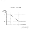
- Fig. 8 is a graph showing one example of the target slip ratio table.
- the ordinate indicates the target slip ratio of the wheel
- the abscissa indicates an absolute value of the lateral sliding acceleration of the wheel.
- the target slip ratio table as indicated by a thick solid line, a relationship between the absolute value of the lateral sliding acceleration of the wheel and the target slip ratio of the wheel is set in advance.
- the target slip ratio table is stored in the ROM 62 of Fig. 3 .
- the target slip ratio in a range in which the absolute value of the lateral sliding acceleration is between a value a1 and a value a2, the target slip ratio is set to decrease from a value b1 to a value b2 as the absolute value of the lateral sliding acceleration increases.
- the value a2 is larger than the value a1.
- the value b2 is smaller than the value b1.
- the target slip ratio is set to the constant value b1.
- the target slip ratio is set to the constant value b2.
- the value b1 of the target slip ratio is 15 %, for example, and the value b2 of the target slip ratio is 5 %, for example.
- the target slip ratio is set in this manner, so that the larger the absolute value of the lateral sliding acceleration is, the lower the target slip ratio is, when the absolute value of the lateral sliding acceleration of the wheel is in the range between the value a1 and the value a2.
- the lateral sliding of the wheel can be appropriately inhibited while the brake force for the wheel is ensured.
- the target slip ratio is kept at the minimum value b2.
- the target slip ratio is kept at the maximum value b1.
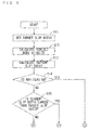
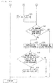
- Figs. 9 and 10 are flow charts of the ABS control process based on the ABS control program according to the first embodiment.
- the ABS control process of Figs. 9 and 10 is repeatedly performed in a period of not less than 1 msec and not more than 20 msec, for example.
- the CPU 61 acquires the target slip ratio corresponding to the absolute value of the lateral sliding acceleration of the wheel supplied from the lateral sliding acceleration calculator 53 of Fig. 5 from the target slip ratio table stored in the ROM 62 of Fig 3 , thereby setting the target slip ratio of the wheel (step S11). In this case, it is not necessary to perform a calculation process for calculating the target slip ratio. Thus, the target slip ratio is easily set in a short period of time.
- the CPU 61 calculates the vehicle body velocity V based on the results of detection supplied from the longitudinal acceleration sensor 43, the front wheel velocity sensor 44 and the rear wheel velocity sensor 45, and amounts of operation of the brake lever 16 and the brake pedal 23 (step S12).
- the CPU 61 calculates the current slip ratio of the wheel (step S13). Specifically, the CPU 61 calculates the front wheel peripheral velocity Vwf based on the result of detection supplied from the front wheel velocity sensor 44, for example. Thereafter, the CPU 61 calculates the current slip ratio SLf of the front wheel 14 by the above-mentioned formula (3) based on the vehicle body velocity V and the front wheel peripheral velocity Vwf. Alternatively, the CPU 61 calculates the rear wheel peripheral velocity Vwr based on the result of detection supplied from the rear wheel velocity sensor 45, for example. Thereafter, the CPU 61 calculates the current slip ratio SLr of the rear wheel 82 by the above-mentioned formula (4) based on the vehicle body velocity V and the rear wheel peripheral velocity Vwr.
- the CPU 61 determines whether the ABS flag stored in the RAM 63 of Fig. 3 is in the ON state (step S14).
- the ABS flag of the present example is used to determine whether the fluid pressure of the wheel cylinder provided to correspond to the wheel is being adjusted (the fluid pressure is increasing or decreasing in the present example) by the fluid pressure control unit 30 of Fig. 3 .
- the ON state of the ABS flag corresponds to a state in which the fluid pressure of the wheel cylinder is being adjusted (the fluid pressure is increasing or decreasing in the present example) by the fluid pressure control unit 30. That is, the ON state of the ABS flag indicates that the ABS is activated (the antilock brake operation is being performed).
- An OFF state of the ABS flag corresponds to a state in which the fluid pressure of the wheel cylinder is not being adjusted by the fluid pressure control unit 30. That is, the OFF state of the ABS flag indicates that the ABS is not activated (the antilock brake operation is being stopped.) In an initial state, the ABS flag is in the OFF state.
- the CPU 61 determines whether the current slip ratio of the wheel calculated in the latest step S13 is larger than the target slip ratio set in the latest step S11 (step S15).
- the margin of the lateral force is a positive value.
- the CPU 61 maintains the state in which the ABS is not activated and returns to the process of the step S11.
- step S15 when the current slip ratio is larger than the target slip ratio, the margin of the lateral force is a negative value. Thus, the lateral force generated between the wheel and the road surface is insufficient, so that the lateral sliding of the wheel occurs. Therefore, it is necessary to increase the margin of the lateral force to a value not less than 0 in order to inhibit the lateral sliding of the wheel. Therefore, the CPU 61 sets the ABS flag in the ON state (step S16). Thus, the ABS is activated.
- the CPU 61 determines whether the current slip ratio of the wheel calculated in the latest step S13 is larger than the target slip ratio set in the latest step S11 (step S21).
- the CPU 61 increases the WC fluid pressure of the wheel by controlling the fluid pressure control unit 30 (step S22). Thus, large brake force can be generated between the wheel and the road surface.
- step S22 when the state in which the WC fluid pressure is not increased is changed to the state in which the WC fluid pressure is increased, the CPU 61 starts a built-in timer.
- the CPU 61 determines whether a predetermined time period has elapsed since the start of the increase of the WC fluid pressure (step S23).
- the CPU 61 sets the ABS flag in the OFF state (step S24) and returns to the process of the step S11. Thus, the ABS is stopped. At this time, the CPU 61 resets the built-in timer. On the one hand, when the predetermined time period has not elapsed since the start of the increase of the WC fluid pressure, the CPU 61 returns to the process of the step S11.
- step S21 when the current slip ratio is larger than the target slip ratio, the lateral sliding of the wheel occurs as described above in the process of the step S15. Therefore, the CPU 61 decreases the WC fluid pressure of the wheel by controlling the fluid pressure control unit 30 (step S25). Thus, the lateral sliding of the wheel can be inhibited. Thereafter, the CPU 61 returns to the process of the step S11.
- the fluid pressure control unit 30 is controlled by the ABS control process such that the slip ratio of the wheel becomes close to the target slip ratio set in the step S11.
- the ABS is stopped.
- Fig. 11 is a diagram showing one example of the ABS control process of when the vehicle body velocity of the motorcycle 100 decreases due to the brake operation in the first embodiment.
- An upper graph of Fig. 11 shows a relationship between the lateral sliding acceleration of the wheel and the time.
- the ordinate indicates the absolute value of the lateral sliding acceleration
- the abscissa indicates the time.
- a middle graph of Fig. 11 shows a relationship between each of the peripheral velocity of the wheel and the vehicle body velocity, and the time.
- the ordinate indicates the velocity
- the abscissa indicates the time.
- the vehicle body velocity is indicated by a thick solid line
- the peripheral velocity of the wheel is indicated by a solid line.
- the target slip ratio converted into the peripheral velocity of the wheel (hereinafter referred to as a converted target slip ratio) is indicated by a one-dot dash line.
- a lower graph of Fig. 11 shows a relationship between the WC fluid pressure and the time.
- the ordinate indicates the WC fluid pressure used for braking of the wheel
- the abscissa indicates the time.
- substantially constant low lateral sliding acceleration is generated at the wheel in periods from a time point t1 to t5, t11 to t13.
- lateral sliding acceleration larger than the lateral sliding acceleration in the periods from the time point t1 to t5, t11 to t13 is generated.
- the brake operation of the wheel is started by the rider at the time point t1.
- the WC fluid pressure increases from the time point t1 to the time point t2.
- the peripheral velocity of the wheel decreases to be gradually spaced apart from the vehicle body velocity and become close to the converted target slip ratio. That is, the slip ratio of the wheel increases.
- the peripheral velocity of the wheel is equal to the converted target slip ratio at the time point t2 and is lower than the converted target slip ratio after the time point t2.
- the processes of the above-mentioned steps S16, S21, S25 are performed.
- the WC fluid pressure decreases from the time point t2 to the time point t3, and the peripheral velocity of the wheel increases to become close to the converted target slip ratio.
- the peripheral velocity of the wheel is equal to the converted target slip ratio at the time point t3 and is higher than the converted target slip ratio after the time point t3.
- the process of the step S22, described above, is performed.
- the WC fluid pressure increases from the time point t3 to the time point t4, and the peripheral velocity of the wheel decreases to become close to the converted target slip ratio.
- the peripheral velocity of the wheel is equal to the converted target slip ratio at the time point t4 and is lower than the converted target slip ratio after the time point t4.
- the WC fluid pressure decreases, and the peripheral velocity of the wheel increases to become close to the converted target slip ratio.
- the increase and decrease of the WC fluid pressure are repeated every time a magnitude relationship between the peripheral velocity of the wheel and the converted target slip ratio is inverted, and the peripheral velocity of the wheel changes to become close to the converted target slip ratio. That is, the slip ratio of the wheel changes to become close to the target slip ratio.
- the lateral sliding acceleration increases in a period from the time point t5 to t11. Therefore, in the period from the time point t5 to t11, the converted target slip ratio is larger than other periods from the time point t1 to t5, t11 to t13. That is, the target slip ratio is small.
- the center of amplitude of the peripheral velocity of the wheel changes together with the converted target slip ratio to become close to the vehicle body velocity. That is, the slip ratio of the wheel decreases.
- the converted target slip ratio is low, and the target slip ratio is large.
- the converted target slip ratio is high, and the target slip ratio is small.
- the fluid pressure control unit 30 is controlled such that the slip ratio of the vehicle becomes close to the target slip ratio.
- the CPU 61 changes the target slip ratio by the correction process based on the magnitude of the lateral sliding acceleration of the wheel such that the margin of the maximum lateral force is ensured.
- the lateral sliding of the wheel can be appropriately inhibited.
- the target slip ratio is high, so that an amount of decrease of the brake force for the wheel is small. Therefore, sufficient deceleration is performed at the time of braking.
- Fig. 12 is a block diagram showing a configuration of the brake control device included in the motorcycle according to the second embodiment.
- the brake control device 200 according to the second embodiment further includes a front wheel fluid pressure sensor 46 and a rear wheel fluid pressure sensor 47 in addition to the configuration of the brake control device 200 ( Fig. 3 ) according to the first embodiment.
- the front wheel fluid pressure sensor 46 is attached to the wheel cylinder WC1.
- the front wheel fluid pressure sensor 46 detects the WC fluid pressure of the wheel cylinder WC1 and supplies a result of detection to the CPU 61 of the ECU 60 for ABS.
- the rear wheel fluid pressure sensor 47 is attached to the wheel cylinder WC2.
- the rear wheel fluid pressure sensor 47 detects the WC fluid pressure of the wheel cylinder WC2 and supplies a result of detection to the CPU 61 of the ECU 60 for ABS.
- the CPU 61 calculates the brake force supplied to the front wheel 14 by the wheel cylinder WC1 and the brake rotor BR1 based on the result of detection supplied from the front wheel fluid pressure sensor 46. Similarly, the CPU 61 calculates the brake force supplied to the rear wheel 82 by the wheel cylinder WC2 and the brake rotor BR2 based on the result of detection supplied from the rear wheel fluid pressure sensor 47.
- the WC fluid pressure of the wheel cylinder WC1 is represented by PWCf
- a cross sectional area of the wheel cylinder WC1 is represented by AWCf
- friction coefficient of the brake pad incorporated in the brake caliper together with the wheel cylinder WC1 is represented by ⁇ f.
- the number of discs of the brake rotor BR1 is represented by nDf
- an effective radius of the disc of the brake rotor BR1 is represented by RDf
- an effective radius of a tire of the front wheel 14 is represented by RWf.
- the brake force BFf supplied to the front wheel 14 can be calculated by a following formula (5).
- BFf PWCf ⁇ AWCf ⁇ ⁇ f ⁇ nDf ⁇ RDf / RWf
- the WC fluid pressure of the wheel cylinder WC2 is represented by PWCr
- a cross sectional area of the wheel cylinder WC2 is represented by AWCr
- friction coefficient of the brake pad incorporated in the brake caliper together with the wheel cylinder WC2 is represented by ⁇ r.
- the number of discs of the brake rotor BR2 is represented by nDr
- an effective radius of the disc of the brake rotor BR2 is represented by RDr
- an effective radius of a tire of the rear wheel 82 is represented by RWr.
- the brake force BFr supplied to the rear wheel 82 can be calculated by a following formula (6).
- BFr PWCr ⁇ AWCr ⁇ ⁇ r ⁇ nDr ⁇ RDr / RWr
- the CPU 61 controls the front wheel fluid pressure circuit 30A and the rear wheel fluid pressure circuit 30B based on the brake force BFf, BFr calculated as described above.
- Fig. 13 is a graph for explaining the basic idea of the second embodiment.
- a relationship between the slip ratio on a predetermined road surface (a dry asphalt road surface, for example) and each of the brake force and the maximum lateral force is shown in Fig. 13 .
- the maximum lateral force refers to the maximum value of the lateral force that can be generated between the wheel (the front wheel 14 or the rear wheel 82) and the road surface.
- the ordinate indicates the brake force or the lateral force
- the abscissa indicates the slip ratio.
- the brake force generated between the wheel (the front wheel 14 or the rear wheel 82) and the road surface is indicated by a one-dot dash line.
- the maximum lateral force is indicated by a solid line.
- the target slip ratio table of Fig. 8 is stored in the ROM 62 of the ECU 60 for ABS.
- the target slip ratio changes in the range from the value b1 to b2 according to the absolute value of the lateral sliding acceleration of the wheel.
- the target slip ratio is set to the maximum value b1.
- the brake force exerted between the wheel and the road surface is substantially the maximum. Letting the value of the brake force in this case be BFmax.
- the brake force exerted between the wheel and the road surface in the range from the value b1 to b2 of the slip ratio is approximated by a straight line extending from an origin to coordinates (b1, BFmax).
- the brake force exerted between the wheel and the road surface when the slip ratio is a value b3 is a value BFc.
- the value b3 is smaller than the value b1.
- a difference value DF between the maximum value BFmax and the value BFc of the brake force is an amount of decrease (an amount of insufficiency) of the brake force of when the target slip ratio decreases from the maximum value b1 to the value b3.
- the CPU 61 calculates an amount of decrease of the brake force for the front wheel 14 during the antilock brake operation of the front wheel 14. It is considered that the brake force BFf calculated by the above-mentioned formula (5) is the brake force exerted between the front wheel 14 and the road surface, the maximum value of the target slip ratio that can be set by the target slip ratio table (the above-mentioned value b1) is represented by SLmax, and the value of the currently set target slip ratio (the above-mentioned value b3) is represented by SL.
- the amount of decrease DFf of the brake force for the front wheel 14 can be calculated by a following formula (7).
- the CPU 61 calculates an amount of decrease of the brake force for the rear wheel 82.
- the brake force BFr calculated by the above-mentioned formula (6) is the brake force exerted between the rear wheel 82 and the road surface
- the maximum value of the target slip ratio that can be set by the target slip ratio table (the above-mentioned value b1) is represented by SLmax
- the value of the currently set target slip ratio (the above-mentioned value b3) is represented by SL.
- the amount of decrease DFr of the brake force for the rear wheel 82 can be calculated by a following formula (8).
- DFr SLmax / SL - 1 ⁇ BFr
- the slip ratio of the wheel on which the antilock brake operation is not performed is not more than the target slip ratio. Therefore, in a range in which the slip ratio of the wheel on which the antilock brake operation is not performed does not exceed the target slip ratio, the brake force supplied to the wheel can be increased.
- the CPU 61 controls the rear wheel fluid pressure circuit 30B to compensate part or all of the amount of decrease DFf of the brake force for the front wheel 14 generated by the correction process of the ABS of the front wheel 14 (the decrease of the target slip ratio).
- the CPU 61 controls the front wheel fluid pressure circuit 30A to compensate part or all of the amount of decrease DFr of the brake force for the rear wheel 82 generated by the correction process of the ABS of the rear wheel 82 (the decrease of the target slip ratio).
- the ABS control programs for the front wheel 14 and the rear wheel 82 are respectively and independently performed by the CPU 61 of Fig. 12 .
- the ABS control process based on each ABS control program and a brake force compensation process, described below, are performed.
- Each ABS control process includes the compensation process that changes the target slip ratio.
- one wheel of the front wheel 14 and the rear wheel 82 is referred to as a first wheel
- the other wheel of the front wheel 14 and the rear wheel 82 is referred to as a second wheel.
- the front wheel 14 is equivalent to the first wheel
- the rear wheel is equivalent to the second wheel
- the front wheel 14 is equivalent to the second wheel.
- the target slip ratio table is used for the correction process in the ABS control process.
- the target slip ratio table the target slip ratio table of Fig. 8 can be used, for example.
- Figs. 14 and 15 are flow charts of the ABS control process based on the ABS control program according to the second embodiment.
- the ABS control process of Figs. 14 and 15 is repeatedly performed in a period of not less than 1 msec and not more than 20 msec, for example. Further, while only the ABS control process for the first wheel is described in the following description, the ABS control process for the second wheel is performed independently from the ABS control process for the first wheel.
- the CPU 61 sets the target slip ratio of the first wheel by acquiring the target slip ratio corresponding to the absolute value of the lateral sliding acceleration of the first wheel supplied from the lateral sliding acceleration calculator 53 of Fig. 5 from the target slip ratio table stored in the ROM 62 of Fig. 12 (step S31).
- the CPU 61 calculates the vehicle body velocity V similarly to the process of the step S12 of Fig. 9 (step S32). Further, the CPU 61 calculates the current slip ratio of the first wheel similarly to the process of the step S13 of Fig. 9 (step S33).
- the CPU 61 determines whether the ABS flag of the first wheel stored in the RAM 63 of Fig. 12 is in the ON state (step S34).
- the ON state of the ABS flag of the first wheel indicates that the ABS is activated for the first wheel.
- the OFF state of the ABS flag of the first wheel indicates that the ABS is not activated for the first wheel. In the initial state, the ABS flag of the first wheel is in the OFF state.
- the CPU 61 determines whether the current slip ratio of the first wheel calculated in the latest step S33 is larger than the target slip ratio of the first wheel set in the latest step S31 (step S35).
- the CPU 61 maintains the state in which the ABS is not activated for the first wheel, and stores 0 in the RAM 63 as the amount of decrease of the brake force of the first wheel (step S36). Further, the CPU 61 performs the brake force compensation process (step S37). Details of the brake force compensation process of the step S37 will be described below. Thereafter, the CPU 61 returns to the process of the step S31.
- step S35 when the current slip ratio of the first wheel is larger than the target slip ratio of the first wheel, the margin of the lateral force of the first wheel is a negative value, and the lateral sliding of the first wheel occurs. Therefore, the CPU 61 sets the ABS flag of the first wheel in the ON state similarly to the step S16 of Fig. 10 in order to inhibit the lateral sliding of the first wheel (step S38). Thus, the ABS is activated for the first wheel.
- the CPU 61 determines whether the current slip ratio of the first wheel calculated in the latest step S33 is larger than the target slip ratio of the first wheel set in the latest step S31 (step S41).
- the CPU 61 performs the process similar to the steps S22, S23 of Fig. 10 . That is, the CPU 61 increases the WC fluid pressure of the first wheel (step S42) and determines whether a predetermined time period has elapsed since the start of the increase of the WC fluid pressure of the first wheel (step S43).
- the CPU 61 sets the ABS flag of the first wheel in the OFF state similarly to the step S24 of Fig. 10 (step S44) and returns to the process of the step S31. Thus, the ABS for the first wheel is stopped.
- the CPU 61 decreases the WC fluid pressure of the first wheel similarly to the step S25 of Fig. 10 (step S45).
- the CPU 61 calculates the amount of decrease of the brake force for the first wheel using the above-mentioned formula (7), and stores the result of calculation in the RAM 63 as the amount of decrease of the brake force of the first wheel (step S46). The result of calculation in this case is larger than 0. Thereafter, the CPU 61 returns to the process of the step S31.
- the ABS control process for the second wheel a process in which "the first wheel" of each step in the above-mentioned ABS control process for the first wheel is changed to "the second wheel” is performed.
- the CPU 61 stores 0 in the RAM 63 as the amount of decrease of the brake force of the second wheel in the step equivalent to the step S36, described above. Thereafter, the CPU 61 performs the brake force compensation process.
- the CPU 61 calculates the amount of decrease of the brake force for the second wheel using the above-mentioned formula (8) in the step equivalent to the step S46, described above. A result of calculation in this case is larger than 0. Further, the CPU 61 stores the result of calculation in the RAM 63 as the amount of decrease of the brake force of the second wheel.
- the ABS control processes for the first wheel and the second wheel are performed, whereby 0 is stored in the RAM 63 as the amount of decrease of the brake force of the first wheel when the ABS is not activated for the first wheel. Further, when the ABS is activated for the first wheel, the result of calculation of the amount of decrease of the brake force of the first wheel larger than 0 is stored in the RAM 63. Similarly, when the ABS is not activated for the second wheel, 0 is stored in the RAM 63 as the amount of decrease of the brake force of the second wheel. Further, when the ABS is activated for the second wheel, the result of calculation of the amount of decrease of the brake force of the second wheel larger than 0 is stored in the RAM 63.
- Fig. 16 is a flow chart of the brake force compensation process of the step S37 of Fig. 15 .
- the CPU 61 calculates the WC fluid pressure of the wheel cylinder WC1 required in order to acquire the brake force equivalent to the amount of decrease of the brake force of the second wheel based on the amount of decrease of the brake force of the second wheel stored in the RAM 63 using the above-mentioned formula (5) (step S51).
- the CPU 61 increases the WC fluid pressure of the wheel cylinder WC1 in a range in which the slip ratio of the first wheel does not exceed the target slip ratio based on the calculated WC fluid pressure (step S52) and returns to the process of the step S31 of Fig. 14 .
- step S51 when the amount of decrease of the brake force of the second wheel stored in the RAM 63 is 0, the ABS is not activated for the second wheel.
- the WC fluid pressure of the wheel cylinder WC1 required in order to acquire the brake force equivalent to the amount of decrease of the brake force of the second wheel is 0. Therefore, the WC fluid pressure of the first wheel is not increased in the step S52.
- the CPU 61 calculates the WC fluid pressure of the wheel cylinder WC2 required in order to acquire the brake force equivalent to the amount of decrease of the brake force of the first wheel based on the amount of decrease of the brake force of the first wheel stored in the RAM 63 using the above-mentioned formula (6). Thereafter, in the step equivalent to the step S52, described above, the CPU 61 increases the WC fluid pressure of the wheel cylinder WC2 in a range in which the slip ratio of the second wheel does not exceed the target slip ratio based on calculated WC fluid pressure and returns to the process of step S31 of Fig. 14 .
- the ABS is not activated for the first wheel.
- the WC fluid pressure of the wheel cylinder WC2 required in order to acquire the brake force equivalent to the amount of decrease of the brake force of the first wheel is 0. Therefore, the WC fluid pressure of the second wheel is not increased in the subsequent step.
- Fig. 17 is a diagram showing one example of the ABS control process of when the vehicle body velocity of the motorcycle 100 decreases due to the brake operation in the second embodiment.
- a top graph of Fig. 17 shows a relationship between the lateral sliding acceleration of the first wheel and the time.
- the ordinate indicates the absolute value of the lateral sliding acceleration
- the abscissa indicates the time.
- a second graph from the top of Fig. 17 shows a relationship between the brake force supplied to each of the first wheel and the second wheel, and the time period.
- the ordinate indicates the brake force
- the abscissa indicates the time.
- the brake force supplied to the first wheel is indicated by a solid line
- the brake force supplied to the second wheel is indicated by a thick dotted line.
- a third graph from the top of Fig. 17 shows a relationship between each of the peripheral velocity of the first wheel and the vehicle body velocity, and the time.
- the ordinate indicates the velocity
- the abscissa indicates the time.
- the vehicle body velocity is indicated by a thick solid line
- the peripheral velocity of the first wheel is indicated by a solid line.
- the converted target slip ratio of the first wheel is indicated by a one-dot dash line.
- a bottom graph of Fig. 17 indicates a relationship between the WC fluid pressure of each of the first wheel and the second wheel, and the time.
- the ordinate indicates the WC fluid pressure
- the abscissa indicates the time.
- the WC oil pressure of the first wheel is indicated by a solid line
- the WC oil pressure of the second wheel is indicated by a thick dotted line.
- substantially constant low lateral sliding acceleration is generated at the first wheel in periods from time point t1 to t5, t11 to t13.
- lateral sliding acceleration larger than the lateral sliding acceleration in the periods from the time point t1 to t5 is generated at the first wheel.
- the lateral sliding acceleration generated at the first wheel, the peripheral velocity of the first wheel, the converted target slip ratio of the first wheel and the WC fluid pressure of the first wheel change.
- the converted target slip ratio of the first wheel is large. That is, the target slip ratio of the first wheel is small.
- the brake force supplied to the first wheel is small.
- the amount of decrease of the brake force of the first wheel is compensated by the brake force supplied to the second wheel by the brake force compensation process of the step S37, described above.
- the WC fluid pressure of the second wheel is temporarily increased in the period from the time point t5 to t11.
- the brake force supplied to the second wheel temporarily increases in the period from the time point t5 to t11.
- the amount of decrease of the brake force of the rear wheel 82 generated by the correction process of the ABS of the rear wheel 82 is compensated by the brake force supplied to the first wheel. As a result, the decrease of the brake force exerted on the entire motorcycle 100 is inhibited.
- the ABS is activated for the front wheel 14 and the ABS is not activated for the rear wheel 82
- the amount of decrease of the brake force of the front wheel 14 generated by the correction process of the ABS of the front wheel 14 is compensated by the brake force supplied to the rear wheel 82.
- the decrease of the brake force exerted on the entire motorcycle 100 is inhibited.
- the correction of the antilock brake operation may be performed by a following method.
- the target slip ratio in the antilock brake operation is constant.
- the target slip ratio of the present example is referred to as a fixed target slip ratio such that the target slip ratio used in the above-mentioned embodiment can be discriminated.
- a WC fluid pressure decrease rate table is stored in the ROM 62 of the ECU 60 for ABS instead of the target slip ratio table of Fig. 8 .
- Fig. 18 is a graph showing one example of the WC fluid pressure decrease rate table.
- the ordinate indicates the decrease rate of the WC fluid pressure
- the abscissa indicates the absolute value of the lateral sliding acceleration of the wheel.
- the WC fluid pressure decrease rate table a relationship between the absolute value of the lateral sliding acceleration and the decrease rate of the WC fluid pressure of the wheel is set in advance.
- the decrease rate of the WC fluid pressure is set to increase from a value c1 to a value c2 as the absolute value of the lateral sliding acceleration increases.
- the value a2 is larger than the value a1.
- the value c2 is larger than the value c1.
- the decrease rate of the WC fluid pressure is set to the constant value c1.
- the decrease rate of the WC fluid pressure is set to the constant value c2.
- the decrease rate of the WC fluid pressure is set in this manner, so that the larger the absolute value of the lateral sliding acceleration is, the higher the decrease rate of the WC fluid pressure is, when the absolute value of the lateral sliding acceleration of the wheel is in the range between the value a1 and the value a2. Specifically, the larger the absolute value of the lateral sliding acceleration is, the more sufficiently the CPU 61 increases the rotation velocity of the pumps 33a, 33b of when the WC fluid pressure is decreased.
- the decrease rate of the WC fluid pressure is larger than an increase rate of the WC fluid pressure, so that a center value of an amplitude of the slip ratio of the wheel (hereinafter referred to as an average slip ratio) changes to be lower than the fixed target slip ratio.
- an average slip ratio a center value of an amplitude of the slip ratio of the wheel
- the margin of the maximum lateral force increases similarly to the above-mentioned embodiment.
- Fig. 19 is a diagram showing one example of the ABS control process of when the vehicle body velocity of the motorcycle 100 decreases due to the brake operation in another embodiment.
- a top graph of Fig. 19 shows a relationship between the lateral sliding acceleration of the wheel and the time.
- the ordinate indicates the absolute value of the lateral sliding acceleration
- the abscissa indicates the time.
- a middle graph of Fig. 19 shows a relationship between each of the peripheral velocity of the wheel and the vehicle body velocity, and the time.
- the ordinate indicates the velocity
- the abscissa indicates the time.
- the vehicle body velocity is indicated by a thick solid line
- the peripheral velocity of the wheel is indicated by a solid line.
- the fixed target slip ratio converted into the peripheral velocity of the wheel (hereinafter referred to as a converted fixed target slip ratio) is indicated by a one-dot and dash line.
- the center of the amplitude of the peripheral velocity of the wheel (hereinafter referred to as an average peripheral velocity) is indicated by a thick dotted line.
- a lower graph of Fig. 19 shows a relationship between the WC fluid pressure and the time.
- the ordinate indicates the WC fluid pressure used for braking of the wheel
- the abscissa indicates the time.
- substantially constant low lateral sliding acceleration is generated at the wheel in a period from time point t1 to t5.
- lateral sliding acceleration larger than the lateral sliding acceleration in the period from the time points t1 to t5 is generated.
- the brake operation of the wheel is started by the rider at the time point t1. Thereafter, an increase and the decrease of the WC fluid pressure are repeated every time a magnitude relationship between the peripheral velocity of the wheel and the converted fixed target slip ratio is inverted in the period from the time point t1 to t5, and the peripheral velocity of the wheel changes to become close to the converted fixed target slip ratio.
- the magnitude of the increase rate of the WC fluid pressure and the magnitude of the decrease rate of the WC fluid pressure are substantially the same. Therefore, in the period from the time point t1 to t5, the average peripheral velocity of the wheel substantially coincides with the converted fixed target slip ratio. That is, the average slip ratio of the wheel substantially coincides with the fixed target slip ratio.
- the lateral sliding acceleration increases in the period from the time point t5 to t12. Therefore, in the period from the time point t5 to t12, the decrease rate of the WC fluid pressure is high and the average peripheral velocity of the wheel is high as compared to the period from the time point t1 to t5. That is, the average slip ratio of the wheel decreases.
- the average peripheral velocity of the wheel changes to become close to the vehicle body velocity regardless of the converted fixed target slip ratio. That is, the average slip ratio of the wheel decreases.
- the average peripheral velocity of the wheel is low, and the average slip ratio of the wheel is large.
- the average peripheral velocity of the wheel is high, and the average slip ratio of the wheel is small.
- the brake force supplied to the wheel decreases. Therefore, in the period from the time point t5 to t12, the deceleration of the vehicle body velocity is small as compared to the period from the time point t1 to t5 due to the decrease of the brake force.
- the lateral sliding acceleration detection device 50 detects the lateral sliding acceleration as one example of a degree of the lateral sliding that occurs in the left-and-right direction of the motorcycle 100 in the above-mentioned embodiment, the invention is not limited to this.
- the slip angle may be detected.
- the slip angle refers to a tilt of a plane passing through a central axis of a tire with respect to an advancing direction of the motorcycle 100 on the road surface.
- the correction of the antilock brake operation may be performed based on the detected slip angle.
- the target slip ratio may be changed such that the larger the magnitude of the slip angle of the wheel is, the smaller the target slip ratio is.
- a slip angle differential value (an amount of change of the slip angle per unit time) may be detected as another example of the degree of the lateral sliding.
- the correction of the antilock brake operation may be performed based on the detected slip angle differential value.
- the CPU 61 of Figs. 3 and 12 calculates the slip ratios SLf, SLr as one example of the current degrees of the longitudinal sliding of the front wheel 14 and the rear wheel 82 in the above-mentioned embodiment, the invention is not limited to this.
- a slip amount (a difference between the peripheral velocity of the wheel and the vehicle body velocity) or a wheel acceleration difference (a difference between the vehicle body acceleration and the wheel acceleration) may be calculated.
- the ABS may be activated based on the calculated slip amount, the wheel acceleration difference or the like.
- the WC fluid pressure of the front wheel 14 and the rear wheel 82 is adjusted by the fluid pressure control unit 30 and the brake hoses L1 to L4 in order to supply the brake force to the front wheel 14 and the rear wheel 82.
- a mechanical type brake that presses the brake pad against the brake rotor may be used by activation of an electric motor instead of the fluid pressure type brake that adjusts the pressure of such brake fluid. In this case, the electric motor is controlled, so that the brake force supplied to the wheel can be adjusted.
- the CPU 61 of Figs. 3 and 12 decreases and increases the WC fluid pressure during the activation of the ABS as shown in Figs. 4(b), 4(c) .
- the WC fluid pressure during the activation of the ABS increases and decreases.
- a period in which the WC fluid pressure is kept at the constant pressure may be provided.
- the CPU 61 closes the holding valve 31 a of Fig. 3 , closes the pressure reducing valve 32a and stops the pump 33a, for example.
- a path of the brake fluid between the front wheel master cylinder 16s and the wheel cylinder WC1 and a path of the brake fluid between the reservoir 34a and the wheel cylinder WC1 are cut off by the holding valve 31a a and the pressure reducing valve 32a.
- the pressure of the brake fluid by the wheel cylinder WC1 is kept constant.
- the WC fluid pressure can be changed at any inclination.
- the WC fluid pressure can be changed such that the amplitude of the slip ratio decreases.
- the brake force exerted between the wheel and the road surface in the range from the value b1 to b2 of the slip ratio is approximated by the straight line extending from the origin position to the coordinates (b1, BFmax).
- the brake force exerted between the wheel and the road surface in the range from the value b1 to b2 of the slip ratio may be approximated by a different straight line or a curve according to the state of the road surface, for example.
- the CPU 61 of Fig. 12 determines the state of the road surface based on the change ratio of the slip ratio. Thereafter, the CPU 61 calculates the amount of decrease of the brake force in the front wheel 14 and the rear wheel 82 by using a formula different from the above-mentioned formulas (7) and (8) based on the approximated straight line or curve according to the result of determination.
- the target slip ratio linearly decreases from the value b1 to b2 as the absolute value of the lateral sliding acceleration increases from the value a1 to a2 in the target slip ratio table of Fig. 8 used in the above-mentioned embodiment, the invention is not limited to this.
- the target slip ratio may decrease in steps or may decrease in a curve from the value b1 to b2.
- the value a1 of the absolute value of the lateral sliding acceleration may be 0.
- the decrease rate of the WC fluid pressure linearly increases from the value c1 to c2 as the absolute value of the lateral sliding acceleration increases from the value a1 to a2 in the above-mentioned WC fluid pressure decrease rate table of Fig. 18
- the invention is not limited to this.
- the decrease rate of the WC fluid pressure may decrease in steps or may decrease in a curve from the value c1 to c2.
- the value a1 of the absolute value of the lateral sliding acceleration may be 0.
- ABS control processes are respectively performed for the front wheel 14 and the rear wheel 82 in the first and second embodiments, the invention is not limited to this.
- the above-mentioned ABS control process may be performed on only one of the front wheel 14 and the rear wheel 82.
- the present invention is not limited to this.
- the present invention can be applied to another straddled vehicle such as a motor tricycle, a four-wheeled automobiles or the like.
- the above-mentioned ABS control process may be performed on every wheel.
- the front wheel 14 or the rear wheel 82 is an example of a first wheel
- the motorcycle 100 is an example of a straddled vehicle
- the brake control device 200 is an example of a brake control device
- the front wheel fluid pressure circuit 30A or the rear wheel fluid pressure circuit 30B is an example of a first brake device.
- the slip ratio of the front wheel 14 or the rear wheel 82 and the slip ratio of the first wheel or the second wheel are examples of a slip ratio of a first wheel and a longitudinal sliding degree of a first wheel
- the CPU 61 is an example of a longitudinal sliding detection device and a controller
- the lateral sliding acceleration detection device 50 is an example of a lateral sliding detection device
- the lateral sliding acceleration detected by the lateral sliding acceleration detection device 50 is an example of a lateral sliding degree
- the target slip ratio of the front wheel 14 or the rear wheel 82 and the target slip ratio of the first wheel or the second wheel are examples of a first target slip ratio and a first target longitudinal sliding degree.
- the value a1 is an example of a first value
- the value a2 is an example of a second value
- the value b1 is an example of a third value
- the value b2 is an example of a fourth value
- the target slip ratio table is an example of a correspondence relationship between magnitude of lateral sliding acceleration of a first wheel and a target slip ratio
- the ROM 62 of the ECU 60 for ABS is an example of a storage.
- the rear wheel 82 or the front wheel 14 is an example of a second wheel
- the rear wheel fluid pressure circuit 30B or the front wheel fluid pressure circuit 30A is an example of a second brake device
- the slip ratio of the rear wheel 82 or the front wheel 14 and the slip ratio of the second wheel or the first wheel are examples of a slip ratio of a second wheel and a longitudinal sliding degree of a second wheel
- the target slip ratio of the rear wheel 82 or the front wheel 14 and the target slip ratio of the second wheel or the first wheel are examples of a second target slip ratio and a second target longitudinal sliding degree.
- the present invention can be effectively utilized as a brake system of various vehicles.
Landscapes
- Engineering & Computer Science (AREA)
- Transportation (AREA)
- Mechanical Engineering (AREA)
- Regulating Braking Force (AREA)
Applications Claiming Priority (2)
| Application Number | Priority Date | Filing Date | Title |
|---|---|---|---|
| JP2013060948 | 2013-03-22 | ||
| PCT/JP2014/001096 WO2014147976A1 (ja) | 2013-03-22 | 2014-02-28 | ブレーキ制御装置およびそれを備える鞍乗型車両 |
Publications (3)
| Publication Number | Publication Date |
|---|---|
| EP2977281A1 true EP2977281A1 (de) | 2016-01-27 |
| EP2977281A4 EP2977281A4 (de) | 2017-01-18 |
| EP2977281B1 EP2977281B1 (de) | 2019-11-13 |
Family
ID=51579678
Family Applications (1)
| Application Number | Title | Priority Date | Filing Date |
|---|---|---|---|
| EP14768740.4A Active EP2977281B1 (de) | 2013-03-22 | 2014-02-28 | Bremssteuerungsvorrichtung und sattelfahrzeug damit |
Country Status (4)
| Country | Link |
|---|---|
| EP (1) | EP2977281B1 (de) |
| JP (1) | JP6262202B2 (de) |
| ES (1) | ES2773312T3 (de) |
| WO (1) | WO2014147976A1 (de) |
Cited By (8)
| Publication number | Priority date | Publication date | Assignee | Title |
|---|---|---|---|---|
| EP3378716A4 (de) * | 2016-06-29 | 2019-01-02 | Yamaha Hatsudoki Kabushiki Kaisha | Sattelfahrzeug |
| WO2020121111A1 (ja) * | 2018-12-10 | 2020-06-18 | ロベルト・ボッシュ・ゲゼルシャフト・ミト・ベシュレンクテル・ハフツング | 制御装置及び制御方法 |
| US10967881B2 (en) | 2017-11-22 | 2021-04-06 | Polaris Industries Inc. | Anti-lock braking system for utility vehicle |
| US11254294B2 (en) | 2018-05-02 | 2022-02-22 | Polaris Industries Inc. | Operating modes using a braking system for an all terrain vehicle |
| US11345433B2 (en) | 2018-01-26 | 2022-05-31 | Shimano Inc. | Brake control device, braking device including brake control device, and brake system |
| US11433863B2 (en) | 2017-03-28 | 2022-09-06 | Polaris Industries Inc. | Anti-lock brake system for all-terrain vehicle |
| US11618422B2 (en) | 2018-11-14 | 2023-04-04 | Polaris Industries Inc. | Operating modes using a braking system for an all terrain vehicle |
| EP4005914A4 (de) * | 2019-07-31 | 2023-12-13 | Hitachi Astemo, Ltd. | Steuerungsvorrichtung für lenkstangenfahrzeug |
Families Citing this family (4)
| Publication number | Priority date | Publication date | Assignee | Title |
|---|---|---|---|---|
| JP6873374B2 (ja) * | 2017-03-14 | 2021-05-19 | 日立Astemo株式会社 | バーハンドル車両用ブレーキ制御装置 |
| KR102203475B1 (ko) * | 2019-08-20 | 2021-01-18 | 엘지전자 주식회사 | 자율 주행 시스템에서 차량을 제어하기 위한 방법 및 장치 |
| JP7707880B2 (ja) * | 2021-11-29 | 2025-07-15 | 株式会社アドヴィックス | 制動制御装置 |
| JP2024145022A (ja) * | 2023-03-31 | 2024-10-15 | 本田技研工業株式会社 | 車両制御システム、及び鞍乗型車両 |
Family Cites Families (12)
| Publication number | Priority date | Publication date | Assignee | Title |
|---|---|---|---|---|
| US4989922A (en) | 1988-11-23 | 1991-02-05 | Lucas Industries Public Limited Company | Method of anti-lock brake control for motorcycle vehicle |
| JP3123099B2 (ja) * | 1991-03-18 | 2001-01-09 | トヨタ自動車株式会社 | 制動力制御装置 |
| DE4244112C2 (de) | 1992-12-24 | 2000-10-12 | Bayerische Motoren Werke Ag | Antiblockierregelsystem für Motorräder |
| JP2590024Y2 (ja) | 1993-07-29 | 1999-02-10 | 日本電気ホームエレクトロニクス株式会社 | 二輪車用アンチロックブレーキ装置 |
| JPH1178836A (ja) * | 1997-09-02 | 1999-03-23 | Toyota Motor Corp | 四輪駆動車の駆動力制御装置 |
| DE10235378B4 (de) | 2002-08-02 | 2015-06-25 | Robert Bosch Gmbh | Verfahren und Vorrichtung zur Bremsenregelung |
| JP2009035120A (ja) * | 2007-08-01 | 2009-02-19 | Bridgestone Corp | 車両制御装置 |
| JP2009241696A (ja) * | 2008-03-31 | 2009-10-22 | Nissin Kogyo Co Ltd | バーハンドル車両用ブレーキ制御装置 |
| JP5375371B2 (ja) * | 2009-06-30 | 2013-12-25 | 株式会社アドヴィックス | 車両運動制御装置 |
| EP2657094B1 (de) * | 2010-12-20 | 2018-06-27 | Bosch Corporation | Bremssystem und bremssteuerungsverfahren |
| US9346510B2 (en) * | 2011-07-28 | 2016-05-24 | Yamaha Hatsudoki Kabushiki Kaisha | Attitude controller and saddle riding type vehicle having the same |
| JP5715523B2 (ja) * | 2011-07-31 | 2015-05-07 | 本田技研工業株式会社 | 自動二輪車用ブレーキシステム |
-
2014
- 2014-02-28 JP JP2015506586A patent/JP6262202B2/ja active Active
- 2014-02-28 WO PCT/JP2014/001096 patent/WO2014147976A1/ja not_active Ceased
- 2014-02-28 ES ES14768740T patent/ES2773312T3/es active Active
- 2014-02-28 EP EP14768740.4A patent/EP2977281B1/de active Active
Cited By (14)
| Publication number | Priority date | Publication date | Assignee | Title |
|---|---|---|---|---|
| EP3378717A4 (de) * | 2016-06-29 | 2019-01-23 | Yamaha Hatsudoki Kabushiki Kaisha | Sattelfahrzeug |
| EP3378715A4 (de) * | 2016-06-29 | 2019-05-01 | Yamaha Hatsudoki Kabushiki Kaisha | Sattelfahrzeug |
| EP3378716A4 (de) * | 2016-06-29 | 2019-01-02 | Yamaha Hatsudoki Kabushiki Kaisha | Sattelfahrzeug |
| US11433863B2 (en) | 2017-03-28 | 2022-09-06 | Polaris Industries Inc. | Anti-lock brake system for all-terrain vehicle |
| US10967881B2 (en) | 2017-11-22 | 2021-04-06 | Polaris Industries Inc. | Anti-lock braking system for utility vehicle |
| US12397809B2 (en) | 2017-11-22 | 2025-08-26 | Polaris Industries Inc. | Anti-lock braking system for utility vehicle |
| US11897493B2 (en) | 2017-11-22 | 2024-02-13 | Polaris Industries Inc. | Anti-lock braking system for utility vehicle |
| US11345433B2 (en) | 2018-01-26 | 2022-05-31 | Shimano Inc. | Brake control device, braking device including brake control device, and brake system |
| US12397759B2 (en) | 2018-05-02 | 2025-08-26 | Polaris Industries, Inc. | Operating modes using a braking system for an all terrain vehicle |
| US11254294B2 (en) | 2018-05-02 | 2022-02-22 | Polaris Industries Inc. | Operating modes using a braking system for an all terrain vehicle |
| US11618422B2 (en) | 2018-11-14 | 2023-04-04 | Polaris Industries Inc. | Operating modes using a braking system for an all terrain vehicle |
| WO2020121111A1 (ja) * | 2018-12-10 | 2020-06-18 | ロベルト・ボッシュ・ゲゼルシャフト・ミト・ベシュレンクテル・ハフツング | 制御装置及び制御方法 |
| US12043236B2 (en) | 2018-12-10 | 2024-07-23 | Robert Bosch Gmbh | Controller and control method |
| EP4005914A4 (de) * | 2019-07-31 | 2023-12-13 | Hitachi Astemo, Ltd. | Steuerungsvorrichtung für lenkstangenfahrzeug |
Also Published As
| Publication number | Publication date |
|---|---|
| WO2014147976A1 (ja) | 2014-09-25 |
| JP6262202B2 (ja) | 2018-01-17 |
| EP2977281B1 (de) | 2019-11-13 |
| ES2773312T3 (es) | 2020-07-10 |
| EP2977281A4 (de) | 2017-01-18 |
| JPWO2014147976A1 (ja) | 2017-02-16 |
Similar Documents
| Publication | Publication Date | Title |
|---|---|---|
| EP2977281B1 (de) | Bremssteuerungsvorrichtung und sattelfahrzeug damit | |
| EP2657094B1 (de) | Bremssystem und bremssteuerungsverfahren | |
| EP3362330B1 (de) | Kurvenbremssteuerung | |
| US9594094B2 (en) | Lateral force estimation system, method of estimating lateral force and vehicle | |
| JP5905955B2 (ja) | ブレーキ装置及び鞍乗型車両 | |
| JP6491340B2 (ja) | 車体挙動制御装置及び車体の挙動の制御方法 | |
| US20150367857A1 (en) | Vehicle-center-of-gravity condition determining apparatus and vehicle behavior control system | |
| EP2759453B1 (de) | Bremssteuerungsvorrichtung für Lenkstangenfahrzeug | |
| JP5962906B2 (ja) | 車両の制動力制御装置 | |
| EP3037309B1 (de) | Steigungswinkelsteuerung system, steigungswinkelsteuerungsverfahren und fahrzeug | |
| JP6491335B2 (ja) | 車体挙動制御装置及び車体の挙動の制御方法 | |
| JP2018197070A (ja) | 車両制御装置 | |
| US12043236B2 (en) | Controller and control method | |
| JP6606114B2 (ja) | バーハンドル車両用ブレーキ制御装置 | |
| JP7673246B2 (ja) | 電動オートバイ用の電気式の駆動モータを動作制御する方法、制御装置およびオートバイシステム | |
| EP2106980B1 (de) | Verfahren und Vorrichtung zur Bestimmung der Querbeschleunigung und Bremssteuerung für ein Fahrzeug mit Lenker | |
| JP2009241742A (ja) | 横加速度の導出方法、横加速度の導出装置およびバーハンドル車両用ブレーキ制御装置 | |
| JP6281878B2 (ja) | 車両用ブレーキ液圧制御装置 | |
| EP4227170A1 (de) | Steuerungsvorrichtung und steuerungsverfahren | |
| JP2009184486A (ja) | 二輪車用ブレーキ装置 | |
| JP5067001B2 (ja) | 車両用制動制御装置 | |
| AU2014245883B9 (en) | Brake fluid pressure control device for vehicle |
Legal Events
| Date | Code | Title | Description |
|---|---|---|---|
| PUAI | Public reference made under article 153(3) epc to a published international application that has entered the european phase |
Free format text: ORIGINAL CODE: 0009012 |
|
| 17P | Request for examination filed |
Effective date: 20151019 |
|
| AK | Designated contracting states |
Kind code of ref document: A1 Designated state(s): AL AT BE BG CH CY CZ DE DK EE ES FI FR GB GR HR HU IE IS IT LI LT LU LV MC MK MT NL NO PL PT RO RS SE SI SK SM TR |
|
| AX | Request for extension of the european patent |
Extension state: BA ME |
|
| DAX | Request for extension of the european patent (deleted) | ||
| A4 | Supplementary search report drawn up and despatched |
Effective date: 20161219 |
|
| RIC1 | Information provided on ipc code assigned before grant |
Ipc: B60T 8/1755 20060101ALI20161213BHEP Ipc: B60T 8/176 20060101AFI20161213BHEP |
|
| GRAP | Despatch of communication of intention to grant a patent |
Free format text: ORIGINAL CODE: EPIDOSNIGR1 |
|
| STAA | Information on the status of an ep patent application or granted ep patent |
Free format text: STATUS: GRANT OF PATENT IS INTENDED |
|
| INTG | Intention to grant announced |
Effective date: 20190523 |
|
| GRAS | Grant fee paid |
Free format text: ORIGINAL CODE: EPIDOSNIGR3 |
|
| GRAA | (expected) grant |
Free format text: ORIGINAL CODE: 0009210 |
|
| STAA | Information on the status of an ep patent application or granted ep patent |
Free format text: STATUS: THE PATENT HAS BEEN GRANTED |
|
| AK | Designated contracting states |
Kind code of ref document: B1 Designated state(s): AL AT BE BG CH CY CZ DE DK EE ES FI FR GB GR HR HU IE IS IT LI LT LU LV MC MK MT NL NO PL PT RO RS SE SI SK SM TR |
|
| REG | Reference to a national code |
Ref country code: CH Ref legal event code: EP Ref country code: AT Ref legal event code: REF Ref document number: 1201351 Country of ref document: AT Kind code of ref document: T Effective date: 20191115 |
|
| REG | Reference to a national code |
Ref country code: DE Ref legal event code: R096 Ref document number: 602014056792 Country of ref document: DE |
|
| REG | Reference to a national code |
Ref country code: IE Ref legal event code: FG4D |
|
| REG | Reference to a national code |
Ref country code: NL Ref legal event code: MP Effective date: 20191113 |
|
| REG | Reference to a national code |
Ref country code: LT Ref legal event code: MG4D |
|
| PG25 | Lapsed in a contracting state [announced via postgrant information from national office to epo] |
Ref country code: LT Free format text: LAPSE BECAUSE OF FAILURE TO SUBMIT A TRANSLATION OF THE DESCRIPTION OR TO PAY THE FEE WITHIN THE PRESCRIBED TIME-LIMIT Effective date: 20191113 Ref country code: PL Free format text: LAPSE BECAUSE OF FAILURE TO SUBMIT A TRANSLATION OF THE DESCRIPTION OR TO PAY THE FEE WITHIN THE PRESCRIBED TIME-LIMIT Effective date: 20191113 Ref country code: NO Free format text: LAPSE BECAUSE OF FAILURE TO SUBMIT A TRANSLATION OF THE DESCRIPTION OR TO PAY THE FEE WITHIN THE PRESCRIBED TIME-LIMIT Effective date: 20200213 Ref country code: GR Free format text: LAPSE BECAUSE OF FAILURE TO SUBMIT A TRANSLATION OF THE DESCRIPTION OR TO PAY THE FEE WITHIN THE PRESCRIBED TIME-LIMIT Effective date: 20200214 Ref country code: NL Free format text: LAPSE BECAUSE OF FAILURE TO SUBMIT A TRANSLATION OF THE DESCRIPTION OR TO PAY THE FEE WITHIN THE PRESCRIBED TIME-LIMIT Effective date: 20191113 Ref country code: BG Free format text: LAPSE BECAUSE OF FAILURE TO SUBMIT A TRANSLATION OF THE DESCRIPTION OR TO PAY THE FEE WITHIN THE PRESCRIBED TIME-LIMIT Effective date: 20200213 Ref country code: FI Free format text: LAPSE BECAUSE OF FAILURE TO SUBMIT A TRANSLATION OF THE DESCRIPTION OR TO PAY THE FEE WITHIN THE PRESCRIBED TIME-LIMIT Effective date: 20191113 Ref country code: PT Free format text: LAPSE BECAUSE OF FAILURE TO SUBMIT A TRANSLATION OF THE DESCRIPTION OR TO PAY THE FEE WITHIN THE PRESCRIBED TIME-LIMIT Effective date: 20200313 Ref country code: SE Free format text: LAPSE BECAUSE OF FAILURE TO SUBMIT A TRANSLATION OF THE DESCRIPTION OR TO PAY THE FEE WITHIN THE PRESCRIBED TIME-LIMIT Effective date: 20191113 Ref country code: LV Free format text: LAPSE BECAUSE OF FAILURE TO SUBMIT A TRANSLATION OF THE DESCRIPTION OR TO PAY THE FEE WITHIN THE PRESCRIBED TIME-LIMIT Effective date: 20191113 |
|
| PG25 | Lapsed in a contracting state [announced via postgrant information from national office to epo] |
Ref country code: IS Free format text: LAPSE BECAUSE OF FAILURE TO SUBMIT A TRANSLATION OF THE DESCRIPTION OR TO PAY THE FEE WITHIN THE PRESCRIBED TIME-LIMIT Effective date: 20200313 Ref country code: HR Free format text: LAPSE BECAUSE OF FAILURE TO SUBMIT A TRANSLATION OF THE DESCRIPTION OR TO PAY THE FEE WITHIN THE PRESCRIBED TIME-LIMIT Effective date: 20191113 Ref country code: RS Free format text: LAPSE BECAUSE OF FAILURE TO SUBMIT A TRANSLATION OF THE DESCRIPTION OR TO PAY THE FEE WITHIN THE PRESCRIBED TIME-LIMIT Effective date: 20191113 |
|
| PG25 | Lapsed in a contracting state [announced via postgrant information from national office to epo] |
Ref country code: AL Free format text: LAPSE BECAUSE OF FAILURE TO SUBMIT A TRANSLATION OF THE DESCRIPTION OR TO PAY THE FEE WITHIN THE PRESCRIBED TIME-LIMIT Effective date: 20191113 |
|
| REG | Reference to a national code |
Ref country code: ES Ref legal event code: FG2A Ref document number: 2773312 Country of ref document: ES Kind code of ref document: T3 Effective date: 20200710 |
|
| PG25 | Lapsed in a contracting state [announced via postgrant information from national office to epo] |
Ref country code: CZ Free format text: LAPSE BECAUSE OF FAILURE TO SUBMIT A TRANSLATION OF THE DESCRIPTION OR TO PAY THE FEE WITHIN THE PRESCRIBED TIME-LIMIT Effective date: 20191113 Ref country code: RO Free format text: LAPSE BECAUSE OF FAILURE TO SUBMIT A TRANSLATION OF THE DESCRIPTION OR TO PAY THE FEE WITHIN THE PRESCRIBED TIME-LIMIT Effective date: 20191113 Ref country code: DK Free format text: LAPSE BECAUSE OF FAILURE TO SUBMIT A TRANSLATION OF THE DESCRIPTION OR TO PAY THE FEE WITHIN THE PRESCRIBED TIME-LIMIT Effective date: 20191113 Ref country code: EE Free format text: LAPSE BECAUSE OF FAILURE TO SUBMIT A TRANSLATION OF THE DESCRIPTION OR TO PAY THE FEE WITHIN THE PRESCRIBED TIME-LIMIT Effective date: 20191113 |
|
| REG | Reference to a national code |
Ref country code: DE Ref legal event code: R097 Ref document number: 602014056792 Country of ref document: DE |
|
| REG | Reference to a national code |
Ref country code: AT Ref legal event code: MK05 Ref document number: 1201351 Country of ref document: AT Kind code of ref document: T Effective date: 20191113 |
|
| PG25 | Lapsed in a contracting state [announced via postgrant information from national office to epo] |
Ref country code: SK Free format text: LAPSE BECAUSE OF FAILURE TO SUBMIT A TRANSLATION OF THE DESCRIPTION OR TO PAY THE FEE WITHIN THE PRESCRIBED TIME-LIMIT Effective date: 20191113 Ref country code: SM Free format text: LAPSE BECAUSE OF FAILURE TO SUBMIT A TRANSLATION OF THE DESCRIPTION OR TO PAY THE FEE WITHIN THE PRESCRIBED TIME-LIMIT Effective date: 20191113 |
|
| PLBE | No opposition filed within time limit |
Free format text: ORIGINAL CODE: 0009261 |
|
| STAA | Information on the status of an ep patent application or granted ep patent |
Free format text: STATUS: NO OPPOSITION FILED WITHIN TIME LIMIT |
|
| REG | Reference to a national code |
Ref country code: CH Ref legal event code: PL |
|
| 26N | No opposition filed |
Effective date: 20200814 |
|
| REG | Reference to a national code |
Ref country code: BE Ref legal event code: MM Effective date: 20200229 |
|
| PG25 | Lapsed in a contracting state [announced via postgrant information from national office to epo] |
Ref country code: MC Free format text: LAPSE BECAUSE OF FAILURE TO SUBMIT A TRANSLATION OF THE DESCRIPTION OR TO PAY THE FEE WITHIN THE PRESCRIBED TIME-LIMIT Effective date: 20191113 Ref country code: LU Free format text: LAPSE BECAUSE OF NON-PAYMENT OF DUE FEES Effective date: 20200228 |
|
| PG25 | Lapsed in a contracting state [announced via postgrant information from national office to epo] |
Ref country code: AT Free format text: LAPSE BECAUSE OF FAILURE TO SUBMIT A TRANSLATION OF THE DESCRIPTION OR TO PAY THE FEE WITHIN THE PRESCRIBED TIME-LIMIT Effective date: 20191113 Ref country code: CH Free format text: LAPSE BECAUSE OF NON-PAYMENT OF DUE FEES Effective date: 20200229 Ref country code: SI Free format text: LAPSE BECAUSE OF FAILURE TO SUBMIT A TRANSLATION OF THE DESCRIPTION OR TO PAY THE FEE WITHIN THE PRESCRIBED TIME-LIMIT Effective date: 20191113 Ref country code: LI Free format text: LAPSE BECAUSE OF NON-PAYMENT OF DUE FEES Effective date: 20200229 |
|
| PG25 | Lapsed in a contracting state [announced via postgrant information from national office to epo] |
Ref country code: IE Free format text: LAPSE BECAUSE OF NON-PAYMENT OF DUE FEES Effective date: 20200228 |
|
| PG25 | Lapsed in a contracting state [announced via postgrant information from national office to epo] |
Ref country code: BE Free format text: LAPSE BECAUSE OF NON-PAYMENT OF DUE FEES Effective date: 20200229 |
|
| PG25 | Lapsed in a contracting state [announced via postgrant information from national office to epo] |
Ref country code: TR Free format text: LAPSE BECAUSE OF FAILURE TO SUBMIT A TRANSLATION OF THE DESCRIPTION OR TO PAY THE FEE WITHIN THE PRESCRIBED TIME-LIMIT Effective date: 20191113 Ref country code: MT Free format text: LAPSE BECAUSE OF FAILURE TO SUBMIT A TRANSLATION OF THE DESCRIPTION OR TO PAY THE FEE WITHIN THE PRESCRIBED TIME-LIMIT Effective date: 20191113 Ref country code: CY Free format text: LAPSE BECAUSE OF FAILURE TO SUBMIT A TRANSLATION OF THE DESCRIPTION OR TO PAY THE FEE WITHIN THE PRESCRIBED TIME-LIMIT Effective date: 20191113 |
|
| PG25 | Lapsed in a contracting state [announced via postgrant information from national office to epo] |
Ref country code: MK Free format text: LAPSE BECAUSE OF FAILURE TO SUBMIT A TRANSLATION OF THE DESCRIPTION OR TO PAY THE FEE WITHIN THE PRESCRIBED TIME-LIMIT Effective date: 20191113 |
|
| P01 | Opt-out of the competence of the unified patent court (upc) registered |
Effective date: 20230527 |
|
| PGFP | Annual fee paid to national office [announced via postgrant information from national office to epo] |
Ref country code: ES Payment date: 20250331 Year of fee payment: 12 |
|
| PGFP | Annual fee paid to national office [announced via postgrant information from national office to epo] |
Ref country code: GB Payment date: 20260219 Year of fee payment: 13 |
|
| PGFP | Annual fee paid to national office [announced via postgrant information from national office to epo] |
Ref country code: DE Payment date: 20260218 Year of fee payment: 13 |
|
| PGFP | Annual fee paid to national office [announced via postgrant information from national office to epo] |
Ref country code: IT Payment date: 20260224 Year of fee payment: 13 |
|
| PGFP | Annual fee paid to national office [announced via postgrant information from national office to epo] |
Ref country code: FR Payment date: 20260218 Year of fee payment: 13 |