EP2977286A1 - Kabeltransportausrüstung - Google Patents
Kabeltransportausrüstung Download PDFInfo
- Publication number
- EP2977286A1 EP2977286A1 EP15178210.9A EP15178210A EP2977286A1 EP 2977286 A1 EP2977286 A1 EP 2977286A1 EP 15178210 A EP15178210 A EP 15178210A EP 2977286 A1 EP2977286 A1 EP 2977286A1
- Authority
- EP
- European Patent Office
- Prior art keywords
- vehicle
- tag
- data
- equipment
- sensor
- Prior art date
- Legal status (The legal status is an assumption and is not a legal conclusion. Google has not performed a legal analysis and makes no representation as to the accuracy of the status listed.)
- Withdrawn
Links
- 238000005259 measurement Methods 0.000 claims abstract description 64
- 238000011084 recovery Methods 0.000 claims description 9
- 238000000034 method Methods 0.000 claims description 6
- 238000004146 energy storage Methods 0.000 claims description 4
- 238000004891 communication Methods 0.000 description 7
- 230000005540 biological transmission Effects 0.000 description 5
- 238000012546 transfer Methods 0.000 description 4
- 238000013459 approach Methods 0.000 description 3
- 239000010432 diamond Substances 0.000 description 2
- 238000005516 engineering process Methods 0.000 description 2
- 238000012545 processing Methods 0.000 description 2
- 230000035882 stress Effects 0.000 description 2
- 230000005678 Seebeck effect Effects 0.000 description 1
- 230000002159 abnormal effect Effects 0.000 description 1
- 230000032683 aging Effects 0.000 description 1
- 238000009529 body temperature measurement Methods 0.000 description 1
- 239000003990 capacitor Substances 0.000 description 1
- 238000010586 diagram Methods 0.000 description 1
- 230000007613 environmental effect Effects 0.000 description 1
- 230000006870 function Effects 0.000 description 1
- 238000001228 spectrum Methods 0.000 description 1
- 230000002618 waking effect Effects 0.000 description 1
Images


Classifications
-
- B—PERFORMING OPERATIONS; TRANSPORTING
- B61—RAILWAYS
- B61B—RAILWAY SYSTEMS; EQUIPMENT THEREFOR NOT OTHERWISE PROVIDED FOR
- B61B12/00—Component parts, details or accessories not provided for in groups B61B7/00 - B61B11/00
- B61B12/06—Safety devices or measures against cable fracture
-
- B—PERFORMING OPERATIONS; TRANSPORTING
- B61—RAILWAYS
- B61B—RAILWAY SYSTEMS; EQUIPMENT THEREFOR NOT OTHERWISE PROVIDED FOR
- B61B12/00—Component parts, details or accessories not provided for in groups B61B7/00 - B61B11/00
- B61B12/002—Cabins; Ski-lift seats
-
- Y—GENERAL TAGGING OF NEW TECHNOLOGICAL DEVELOPMENTS; GENERAL TAGGING OF CROSS-SECTIONAL TECHNOLOGIES SPANNING OVER SEVERAL SECTIONS OF THE IPC; TECHNICAL SUBJECTS COVERED BY FORMER USPC CROSS-REFERENCE ART COLLECTIONS [XRACs] AND DIGESTS
- Y02—TECHNOLOGIES OR APPLICATIONS FOR MITIGATION OR ADAPTATION AGAINST CLIMATE CHANGE
- Y02T—CLIMATE CHANGE MITIGATION TECHNOLOGIES RELATED TO TRANSPORTATION
- Y02T30/00—Transportation of goods or passengers via railways, e.g. energy recovery or reducing air resistance
Definitions
- the present invention relates to a cable transport equipment such as a mechanical lift.
- Cable transport equipment is generally subject to a changing environment, including certain parameters such as loading or climatic conditions, so that it may be necessary to measure the various elements of the equipment in order to better estimate their aging and avoid accidents due to excessive mechanical stress.
- the present invention therefore aims to overcome the aforementioned obstacles of the state of the art and to propose a solution for reliably transmitting data between different elements of a cable transport equipment remote from each other to a central base equipment regardless of the configuration of the cable transportation equipment and environmental conditions.
- the present invention relates to a cable transport equipment comprising at least one vehicle configured to move on a route connecting a departure station, an arrival station and possibly one or more intermediate stations, in which at least one vehicle comprises a single identifier radio frequency tag, called a vehicle RF tag, configured to retrieve and save data from at least one communicating measurement sensor located on the cable transport equipment, said sensor communicator having a measurement unit coupled to a radio tag single identifier, said RF tag sensor, and wherein at least one station comprises a radio frequency reader configured to recover the data saved by the, at least one, label RF of vehicle.
- a vehicle RF tag configured to retrieve and save data from at least one communicating measurement sensor located on the cable transport equipment, said sensor communicator having a measurement unit coupled to a radio tag single identifier, said RF tag sensor, and wherein at least one station comprises a radio frequency reader configured to recover the data saved by the, at least one, label RF of vehicle.
- the path comprises at least one pylon
- the at least one communicating sensor is located at a pylon
- the at least one vehicle RF tag is configured to be awake and powered by the vibrations generated at the passage of a pylon.
- the vehicle RF tag can also be battery powered, by recovering and storing the surrounding energy, which can be, for example, mechanical, electromagnetic or thermal.
- the at least one vehicle RF tag is configured to return to a standby mode after the vehicle has passed a pylon.
- a plurality of vehicles comprises a vehicle RF tag and these vehicle RF tags are configured to transmit the recovered data to the other vehicle RF tags within range, the data being transmitted from a tag RF of vehicle to another until a radio-frequency reader located in a station.
- the vehicle RF tags are configured to retrieve and transmit data through energy from an electric battery or battery or from the recovery and storage of surrounding energy such as recovered energy. from the vibrations caused by the passage of the vehicle at the pylon.
- the RF tags of vehicles comprise energy storage means.
- the at least one communicating sensor is configured to be awakened by the vibrations generated by the passage of a vehicle at a pylon.
- the at least one communicating sensor is configured to be powered by a surrounding power source.
- a plurality of vehicles comprises a vehicle RF tag and, after the first recovery step, the data associated with the at least one measurement are transmitted to other vehicle RF tags located within reach.
- the data associated with the at least one measurement of a vehicle RF tag is transmitted until the recovery of said data at the radio frequency reader.
- RF corresponds to the acronym radio frequency
- RFID corresponds to the acronym radio-frequency identification and corresponds to a radio-frequency identification, for example according to ISO 18000-3 or ISO 15693;
- the present invention relates to a cable transport equipment, for example a gondola or chairlift.
- the cable transport equipment 1 here a chairlift, comprises a plurality of vehicles 3, seats in this case, suspended from a cable 5 connecting a departure station 7 and an arrival station 9.
- the vehicles 3 include radio-frequency communication means, for example tags or RFID "tags" for example of the RFID type that use a frequency spectrum of between 860 and 960 MHz.
- RFID tags covering other frequency bands such as the 433MHz band or the 2.5GHz band can also be used. These RF tags are active, passive or semi-passive. In the case of active RF tags, an internal power source such as, for example, batteries or a battery, supplies the RF tag.
- the tag includes an energy recovery device provided by the environment.
- This energy corresponds, for example, to mechanical energy such as the vibrations generated by the passage at the level of a pylon or to the thermal energy recovered by means of Seebeck effect elements or electromagnetic energy recovered at the level of an antenna.
- the RF tags use the energy provided by the electromagnetic signals received from an RF reader or other active element sending an RF signal.
- these labels are also equipped with mechanical energy recovery systems and electrical energy storage, that is to say system for recovering vibration energy provided to the RF tag.
- these vehicle RF tags may also include photovoltaic light energy recovery systems or other energy recovery systems. Recovered energy that can be stored in batteries, capacitors or any type of element allowing storage of electrical energy.
- the equipment 1 also comprises a plurality of intermediate pylons 11 for supporting and / or compressing the cable 5 carrying the vehicles 3.
- the pylons 11 comprise in particular a bracket supporting a rocker 13 on which are positioned rollers 15 as shown on the figure 2 with a view from above and a side view of the beam 13.
- the rollers 15 are rotatably mounted and are configured to receive and guide the cable 5.
- the vehicles are connected to the cable 1 by a fastener 17 which surrounds the cable 5 so that the passage of a vehicle at a pylon 11 causes vibrations related to the passage of the fastener 17 on the rollers 15. These vibrations are therefore used to "wake up" the RF tag 4 of a vehicle 3, c ' that is, to change it from a sleep or inert mode to an active mode.
- the vibration energy is also used to recover data, for example measurements made by a sensor.
- the sensor may be an internal sensor to the vehicle RF tag 4, in which case the recovered energy is used to perform the measurements or an external sensor located on the vehicle 3 or on the tower 11 or near the tower 11.
- a communicating sensor 6 having a measurement unit coupled with RF or wired communication means, such as for example an RF tag said RF tag sensor, so that the label RF 4 of a vehicle can retrieve the data associated with the measurements by sending an RF signal to the RF tag of the communicating sensor 6.
- the technologies used for the RF sensor tags correspond to the technologies used for the vehicle tags presented previously.
- a communicating sensor 6 may comprise one or more sensors connected by a cable or wireless communication, in particular RF, to a sensor tag which links to the vehicle tag.
- the communicating sensor 6 can be configured to perform measurements at regular intervals, in this case it will have an internal power source and will transfer the last measurement (s) when receiving an RF signal from an RFID tag.
- the communicating sensor 6 can also be awakened and powered by the vibrations generated by the passage of the vehicle at the tower so that the communicating sensor 6 can use this energy to perform the measurements and / or to send the data associated with these measurements taken. to the vehicle RF tag 4 or vehicles 3 located within range.
- the sensor or sensors used in the communicating sensor may be a combination of a temperature sensor, a hygrometric sensor, a stress sensor or any other type of sensor.
- the vehicle RF tag 4 is configured to save the data to an internal memory.
- the RF reader 19 can retrieve the measurements saved by the vehicle RF tag 4 during its passage at the departure station 7.
- the RF reader 19 can also be located in an arrival station or a terminal. intermediate station of the cable transport equipment 1.
- the vehicle RF tag 4 retrieves the data of the communicating sensor (s) 6 when it is moved on the cable transport equipment 1 and transmits the recovered data to a location.
- the vehicle RF tag 4 is also configured to transmit the recovered data to the other vehicle RF tags 4 located in the vicinity, i.e. within the communication range of the RF tag of the vehicle. vehicle 4.
- the communication range of the vehicle RF tags 4 is for example less than 200 meters.
- the other vehicle RF tags 4 located nearby are for example the vehicle RF tags 4 of the preceding vehicle 3, the next vehicle 3 and the vehicle 3 traveling in the opposite direction and located near the tower 11. This transmission of data to the other RF tags of vehicle 4 located in range allows on the one hand to repatriate the data more quickly to the RF reader 19 located at the departure station 7 and on the other hand to create a redundancy of data, allowing avoid data loss.
- the transfer of data between vehicle RF tags 4 can be step by step so that the time required for the RF reader 19 to retrieve the data associated with the measurements is greatly reduced compared to the time required for the vehicle 3 having recovered the data associated with the measurements of the sensor to return to the station where find the RF reader 19.
- the vehicle RF tag 4 retrieves and transmits the data associated with the measurements made to other vehicle RF tags 4 within range.
- the transmitted data may also include other information than measurements such as an alarm associated with a faulty system or an abnormal measurement, the time of measurement, the reference of the sensor ...
- the vibrations cease so that when the data transmission is complete, the vehicle RF tag 4 can return to a standby mode.
- the next awakening is either by receiving an RF signal, for example from another vehicle RF tag 4 or the RF reader 19, or by the vibrations generated at the next tower 11, or another event waking up the label RF.
- the RF reader 19 sends an RF signal to the vehicle RF tag 4 for retrieve the data saved in its internal memory or the vehicle RF tag 4 sends itself the saved data to the RF reader. These data correspond to the measurements recovered at the level of the towers 11 as well as the measurements received from the other vehicle RF tags.
- the RF reader 19 can then compile the set of measurement data and perform the data processing or send these data to a remote station, for example via an Internet connection.
- the RF reader 19 can also send a command to the vehicle RF tag 4, for example to erase the data stored when these data have been retrieved by the RF reader 19.
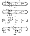
- the figure 3 represents a top view of a chairlift comprising a departure station 7 comprising an RF reader 19 and an arrival station 9 and three intermediate pylons 11 noted P1, P2 and P3. Only certain vehicles or seats 3 are represented by a rhombus. In addition, the seats are each equipped with a vehicle RF tag 4 coupled to a strain gauge located on a seat arm to measure the deformations of the latter. Moreover, the three pylons 11 noted P1, and P2 and P3 are equipped with a communicating sensor 6 respectively corresponding to a thermocouple, a hygrometer and an anemometer.
- the path of a seat noted S and represented by a black diamond throughout the journey from the departure station to return to the departure station 7 will be described.
- the other vehicles 3 are represented by a white diamond.
- the seat preceding the seat S is noted S-1 and the following seat is noted S + 1.
- the seat located on the other side of the pylon will be noted So for the first pylon P1, So 'for the second pylon P2 and So "for the third pylon P3
- the seats preceding and following the seat So are respectively denoted So-1 and So + 1
- the seats preceding and following the seat So 'are respectively denoted So'-1 and So' + 1
- the seats preceding and following the seat So "are respectively denoted So" -1 and So "+1.
- the seat S approaches the first pylon noted P1 so that the seat S-1 is at the pylon P1.
- the vehicle RF tag 4 of the seat S-1 is therefore activated and fed by the vibrations generated by the passage of the seat S-1 at the pylon P1 so that the seat S-1 can send signals to the label. of the seat S, for example data corresponding to measurements retrieved by the vehicle RFID tag 4 of the seat S-1.
- the vehicle RFID tag 4 of the seat S is then awakened by these signals, which enables it, for example, to store the data sent by the RF tag 4 of the seat S-1.
- the measurement data transferred between the vehicle RF tags 4 comprises, for example, the measurement made, an identifier of the sensor having made the measurement and the time at which the measurement was made.
- the seat S is at the first pylon noted P1 and the vehicle RF tag 4 associated with the seat S is thus awakened and powered by the vibrations generated by the passage of the seat S at the P1 pylon.
- the vehicle RF tag 4 therefore performs a measurement of constraints using the associated strain gauge and sends a signal to the communicating temperature sensor 6 or thermocouple positioned on the tower P1 to recover the data associated with the temperature measurement. .
- This data is then stored in the internal memory of the vehicle RF tag 4 associated with the seat S.
- This data is also sent to the vehicle RF tags 4 associated with the seats S-1. S + 1 and So which are in the vicinity of the seat S. This data is then stored in the different vehicle RF tags 4.
- the data received by the RF vehicle tag 4 of the seat So may be returned by the vehicle seat RF tag 4 So to the vehicle RF tags 4 of the seats So-1 and So + 1.
- the vehicle RF tag 4 of the seat S can receive data sent by the seat label So, these data are then stored in the vehicle RF tag 4 associated with the seat S.
- the seat S moves away from the first pylon noted P1 and therefore goes into a standby mode.
- the seat S + 1 is at the pylon P1.
- the vehicle RF tag 4 of the seat S + 1 is therefore activated and fed by the vibrations generated by the passage of the seat S + 1 at the pylon P1 so that the vehicle RF tag 4 of the seat S + 1 can send signals to the vehicle seat RF tag 4 of the seat S, for example data corresponding to measurements retrieved by the vehicle RF tag 4 of the seat S + 1.
- the vehicle RF tag 4 of the seat S is then awakened by these signals, which enables it, for example, to store the data sent by the vehicle RF tag 4 of the seat S + 1.
- the seat S approaches the second pylon noted P2 so that the seat S-1 is at the pylon P2.
- the vehicle RF tag 4 of the seat S-1 is therefore activated and fed by the vibrations generated by the passage of the seat S-1 at the pylon P2 so that the vehicle RF tag 4 of the seat S-1 can send signals to the vehicle seat RF tag 4 of the seat S, for example data corresponding to measurements retrieved by the vehicle RF tag 4 of the seat S-1.
- the vehicle RF tag 4 of the seat S is then awakened and activated by these signals, which enables it, for example, to store the data sent by the vehicle RF tag 4 of the seat S-1.
- the seat So approaches the departure station 7 and the seat So-1 is at the departure station 7 so that the data recovered by the vehicle RF tag 4 of the seat S at the pylon P1 can already be retrieved by the RF reader 19 if they were transferred to the So-1 seat label.
- the seat S is at the second pylon 11 noted P2.
- the vehicle RF tag 4 of the seat S is therefore activated and fed by the vibrations generated by the passage of the seat S at the pylon P2 so that the vehicle RF tag 4 of the seat S can perform a measurement of constraints and retrieve data associated with a measurement of humidity of the communicating sensor 6 including the hygrometer of the pylon P2. These measurements can then be transmitted to the vehicle RF labels 4 of the seats So ', S-1 and S + 1. Once these data have been recovered, the vehicle RF tag 4 of the seat S can store them and send them to the vehicle RF labels 4 of the seats S-1, S + 1 and So ', the latter being able to send back the measurements.
- the seat S is at the third pylon noted P3.
- the vehicle RF tag 4 of the seat S is therefore activated and fed by the vibrations generated by the passage of the seat S at the pylon P3 so that the vehicle RF tag 4 of the seat S can perform a measurement of constraints and recovering data associated with a speed measurement of the communicating sensor 6 comprising the anemometer of the pylon P3.
- This data can then be transmitted to the So ", S-1 and S + 1 seat labels.
- the vehicle's RFID tag 4 can store them in memory and send them to the RF tags. 4 of the seats S-1, S + 1 and So ", the latter being able to send the data to the vehicle RF tag 4 of the seat So -l.
- the data associated with the measurements made at the Pylon P2 are transferred from the vehicle RFID tag 4 from the seat So'-1 to the vehicle RF tag 4 of the seat So'-2 at the pylon P1 so that when the seat So'-2 arrives at the from the departure station 7, the data retrieved by the vehicle RF tag 4 of the seat S at the level of the pylon P2 are retrieved by the RF reader 19.
- the seat label S can retrieve data associated with measurements at the different pylons 11 during its journey from the arrival station 9 to the departure station 7, the data also being transferred to the labels.
- RF vehicle 4 seats in range.
- the seat S arrives at the departure station 7 so that the RF reader 19 can recover the data saved in the internal memory of the vehicle RF tag 4 and in particular the data recovered at the various pylons 11 and that the data retrieved from the vehicle RF tags 4 from the other seats.
- Vehicle RF tags 4 may also include a permanent power source, such as for example a photovoltaic cell or an energy storage element such as a battery, and thus remain in active mode at all times so that the measurements made are transmitted gradually between the vehicle RF tags 4 and arrive in real time at the RF reader 19.
- the communicating sensors 6 can be configured to be awake and to recover the energy of the vibrations generated. by the passage of vehicles 3 at the level of the tower 11.
- the communicating sensor 6 itself that sends the measurement data to the vehicle RF label (s) 4 of the vehicles 3 located within range.
- the latter only having to put the data in memory and / or to transmit the data to the vehicle RF tags 4 of the other vehicles 3.
- vehicle RF tags 4 for example RFID tags, makes it possible to recover measurement data from the energy recovered from the vibrations.
- the plurality of vehicle RF tags 4 is used to transfer the data associated with the measurements of the distributed sensors on the cable transport equipment 1 to the RF reader 19 remote from the sensors while using short-range communications, the transfer being realized. in a relatively short time.
- these communications make it possible to duplicate the transferred data and thus to enhance the overall reliability of the system.
Landscapes
- Engineering & Computer Science (AREA)
- Transportation (AREA)
- Mechanical Engineering (AREA)
- Arrangements For Transmission Of Measured Signals (AREA)
Applications Claiming Priority (1)
| Application Number | Priority Date | Filing Date | Title |
|---|---|---|---|
| FR1457173A FR3024116A1 (fr) | 2014-07-24 | 2014-07-24 | Equipement de transport par cable |
Publications (1)
| Publication Number | Publication Date |
|---|---|
| EP2977286A1 true EP2977286A1 (de) | 2016-01-27 |
Family
ID=51830500
Family Applications (1)
| Application Number | Title | Priority Date | Filing Date |
|---|---|---|---|
| EP15178210.9A Withdrawn EP2977286A1 (de) | 2014-07-24 | 2015-07-24 | Kabeltransportausrüstung |
Country Status (2)
| Country | Link |
|---|---|
| EP (1) | EP2977286A1 (de) |
| FR (1) | FR3024116A1 (de) |
Cited By (4)
| Publication number | Priority date | Publication date | Assignee | Title |
|---|---|---|---|---|
| DE102016206191A1 (de) * | 2016-04-13 | 2017-10-19 | Zf Friedrichshafen Ag | Datenübertragung mittels Seilbahngondel |
| WO2018108636A1 (de) * | 2016-12-12 | 2018-06-21 | Innova Patent Gmbh | Verfahren zum betrieb einer seilbahnanlage und seilbahnanlage zur durchführung dieses betriebsverfahrens |
| WO2021250132A1 (fr) | 2020-06-10 | 2021-12-16 | Poma | Procédé et dispositif de contrôle d'une installation de transport par câble et installation comprenant un tel dispositif de contrôle |
| US11332166B2 (en) * | 2017-06-12 | 2022-05-17 | Innova Patent Gmbh | Cableway with lock monitoring for a vehicle |
Citations (3)
| Publication number | Priority date | Publication date | Assignee | Title |
|---|---|---|---|---|
| WO1995030216A1 (en) * | 1994-04-28 | 1995-11-09 | Doppelmayr Seilbahn-Vertriebs-Gmbh | Ropeway safety monitoring system |
| EP1849675A1 (de) * | 2006-04-25 | 2007-10-31 | Pomagalski S.A. | Verfahren zur Kontrolle einer Seilbahn mit einem Abschnitt zum Regulieren des Abstandes und Vorrichtung zur Durchführung dieses Verfahrens |
| FR2991649A1 (fr) * | 2012-06-06 | 2013-12-13 | Eurolase | Methode de controle de securite pour telesiege |
-
2014
- 2014-07-24 FR FR1457173A patent/FR3024116A1/fr not_active Withdrawn
-
2015
- 2015-07-24 EP EP15178210.9A patent/EP2977286A1/de not_active Withdrawn
Patent Citations (3)
| Publication number | Priority date | Publication date | Assignee | Title |
|---|---|---|---|---|
| WO1995030216A1 (en) * | 1994-04-28 | 1995-11-09 | Doppelmayr Seilbahn-Vertriebs-Gmbh | Ropeway safety monitoring system |
| EP1849675A1 (de) * | 2006-04-25 | 2007-10-31 | Pomagalski S.A. | Verfahren zur Kontrolle einer Seilbahn mit einem Abschnitt zum Regulieren des Abstandes und Vorrichtung zur Durchführung dieses Verfahrens |
| FR2991649A1 (fr) * | 2012-06-06 | 2013-12-13 | Eurolase | Methode de controle de securite pour telesiege |
Cited By (8)
| Publication number | Priority date | Publication date | Assignee | Title |
|---|---|---|---|---|
| DE102016206191A1 (de) * | 2016-04-13 | 2017-10-19 | Zf Friedrichshafen Ag | Datenübertragung mittels Seilbahngondel |
| AT518852A3 (de) * | 2016-04-13 | 2018-09-15 | Zahnradfabrik Friedrichshafen | Datenübertragung mittels Seilbahngondel |
| WO2018108636A1 (de) * | 2016-12-12 | 2018-06-21 | Innova Patent Gmbh | Verfahren zum betrieb einer seilbahnanlage und seilbahnanlage zur durchführung dieses betriebsverfahrens |
| RU2723573C1 (ru) * | 2016-12-12 | 2020-06-16 | Ропетранс Аг | Способ эксплуатации системы подвесной канатной дороги и система подвесной канатной дороги для осуществления этого способа эксплуатации |
| US11198450B2 (en) | 2016-12-12 | 2021-12-14 | Ropetrans Ag | Method for operating a cable car system and cable car system for carrying out this operating method |
| US11332166B2 (en) * | 2017-06-12 | 2022-05-17 | Innova Patent Gmbh | Cableway with lock monitoring for a vehicle |
| WO2021250132A1 (fr) | 2020-06-10 | 2021-12-16 | Poma | Procédé et dispositif de contrôle d'une installation de transport par câble et installation comprenant un tel dispositif de contrôle |
| FR3111315A1 (fr) | 2020-06-10 | 2021-12-17 | Poma | Procédé et dispositif de contrôle d’une installation de transport par câble et installation comprenant un tel dispositif de contrôle |
Also Published As
| Publication number | Publication date |
|---|---|
| FR3024116A1 (fr) | 2016-01-29 |
Similar Documents
| Publication | Publication Date | Title |
|---|---|---|
| WO2014079956A1 (fr) | Bagage comportant un module de geolocalisation associe a un module de communication | |
| EP2977286A1 (de) | Kabeltransportausrüstung | |
| FR3013870A1 (fr) | Systeme de lecture dynamique de donnees de transpondeurs | |
| EP3074917A1 (de) | System zum dynamischen lesen von daten aus transpondern | |
| FR3113328A1 (fr) | Procédé et dispositif de prédiction d’une condition météorologie sur un réseau routier | |
| WO2017216119A1 (fr) | Système de surveillance d'un équipement d'aéronef | |
| EP3642641B1 (de) | Geolokalisierung ohne gps mit einen gemischtem wifi- und lpwan-plotter | |
| FR2928763A1 (fr) | Systeme de suivi d'au moins un dispositif destine a etre transporte | |
| EP4457115A1 (de) | Verfahren und system zur verwaltung einer elektrischen batterievorrichtung eines elektro- oder hybridfahrzeugs | |
| EP3896469B1 (de) | Isolator für elektrische hochspannungsleitungen mit einer leckstrommesseinrichtung mit verlängerter reichweite | |
| EP3501940A1 (de) | Schienenfahrzeug, entsprechendes schienensystem und verfahren zur zusammensetzung des schienenfahrzeugs | |
| WO2014167080A1 (fr) | Marqueur d'identification | |
| WO2015082834A1 (fr) | Système de transport par câble aérien, notamment un télésiège ou télécabine | |
| EP3100465B1 (de) | System und entsprechendes verfahren zur verwaltung einer batterie mit mehreren batteriezellen | |
| EP3492290A1 (de) | Erfassungs- und analysesystem von daten, die von in fahrzeugen eingebauten sensoren ausgesandt werden, entsprechendes verfahren, tragbares kontrollgerät und entsprechende eingebaute kontrolleinheit | |
| EP3182287B1 (de) | Verfahren und vorrichtung der zuverlässigskeitüberwachung eines elektronischen geräts in einem flugzeug | |
| WO2003003290A1 (fr) | Systeme et procede de detection d'individus ou d'objets dans les espaces delimites presentant chacun au moins une entree | |
| FR3030991A1 (fr) | Reseau de dispositifs de mesure communiquant par liaison radio | |
| EP4548504B1 (de) | Verfahren und system zur optischen datensammlung | |
| FR3126815A1 (fr) | Dispositif de gestion de la mise en œuvre d’une limitation du courant destiné à alimenter un objet connecté | |
| FR2938718A1 (fr) | Procede de communication et reseau mettant en oeuvre ce procede | |
| FR3142048A1 (fr) | Système de collecte de données sans fil | |
| EP3847629B1 (de) | Angeschlossenes messgerät für ein flugzeug | |
| FR3049145B1 (fr) | Balise d'observation d'un objet, systeme d'observation et procede de transmission de donnees d'observation associes | |
| FR3115649A1 (fr) | Système de détection de mise en fourrière d’un véhicule |
Legal Events
| Date | Code | Title | Description |
|---|---|---|---|
| PUAI | Public reference made under article 153(3) epc to a published international application that has entered the european phase |
Free format text: ORIGINAL CODE: 0009012 |
|
| AK | Designated contracting states |
Kind code of ref document: A1 Designated state(s): AL AT BE BG CH CY CZ DE DK EE ES FI FR GB GR HR HU IE IS IT LI LT LU LV MC MK MT NL NO PL PT RO RS SE SI SK SM TR |
|
| AX | Request for extension of the european patent |
Extension state: BA ME |
|
| RIN1 | Information on inventor provided before grant (corrected) |
Inventor name: VAN PETEGHEM, BENJAMIN Inventor name: DELILLE, BENOIT Inventor name: DELMAS, BRUNO Inventor name: CAILBAULT, JEAN-FRANCOIS Inventor name: LE DEVENTEC, GAEL |
|
| STAA | Information on the status of an ep patent application or granted ep patent |
Free format text: STATUS: THE APPLICATION IS DEEMED TO BE WITHDRAWN |
|
| 18D | Application deemed to be withdrawn |
Effective date: 20160728 |