EP2977295A1 - Dispositif de direction assistée électrique - Google Patents
Dispositif de direction assistée électrique Download PDFInfo
- Publication number
- EP2977295A1 EP2977295A1 EP13879032.4A EP13879032A EP2977295A1 EP 2977295 A1 EP2977295 A1 EP 2977295A1 EP 13879032 A EP13879032 A EP 13879032A EP 2977295 A1 EP2977295 A1 EP 2977295A1
- Authority
- EP
- European Patent Office
- Prior art keywords
- loss
- voltage
- integrating
- calculating section
- power
- Prior art date
- Legal status (The legal status is an assumption and is not a legal conclusion. Google has not performed a legal analysis and makes no representation as to the accuracy of the status listed.)
- Granted
Links
- 238000010438 heat treatment Methods 0.000 description 14
- 101150073536 FET3 gene Proteins 0.000 description 7
- 101100484930 Saccharomyces cerevisiae (strain ATCC 204508 / S288c) VPS41 gene Proteins 0.000 description 7
- 238000010586 diagram Methods 0.000 description 6
- 101100119059 Saccharomyces cerevisiae (strain ATCC 204508 / S288c) ERG25 gene Proteins 0.000 description 5
- 238000004364 calculation method Methods 0.000 description 5
- 230000006870 function Effects 0.000 description 5
- 230000009467 reduction Effects 0.000 description 5
- 230000007246 mechanism Effects 0.000 description 4
- 230000006641 stabilisation Effects 0.000 description 4
- 238000011105 stabilization Methods 0.000 description 4
- 101150015217 FET4 gene Proteins 0.000 description 2
- 230000002146 bilateral effect Effects 0.000 description 2
- 230000008859 change Effects 0.000 description 2
- 101150079361 fet5 gene Proteins 0.000 description 2
- 230000007935 neutral effect Effects 0.000 description 2
- 230000004044 response Effects 0.000 description 2
- 238000005070 sampling Methods 0.000 description 2
- 238000004904 shortening Methods 0.000 description 2
- 230000002159 abnormal effect Effects 0.000 description 1
- 238000003491 array Methods 0.000 description 1
- 230000006399 behavior Effects 0.000 description 1
- 230000005540 biological transmission Effects 0.000 description 1
- 230000007423 decrease Effects 0.000 description 1
- 230000003247 decreasing effect Effects 0.000 description 1
- 230000000694 effects Effects 0.000 description 1
- 230000007613 environmental effect Effects 0.000 description 1
- 230000005669 field effect Effects 0.000 description 1
- 230000008571 general function Effects 0.000 description 1
- 238000012886 linear function Methods 0.000 description 1
- 230000000630 rising effect Effects 0.000 description 1
- 239000004065 semiconductor Substances 0.000 description 1
Images


Classifications
-
- B—PERFORMING OPERATIONS; TRANSPORTING
- B62—LAND VEHICLES FOR TRAVELLING OTHERWISE THAN ON RAILS
- B62D—MOTOR VEHICLES; TRAILERS
- B62D5/00—Power-assisted or power-driven steering
- B62D5/04—Power-assisted or power-driven steering electrical, e.g. using an electric servo-motor connected to, or forming part of, the steering gear
- B62D5/0457—Power-assisted or power-driven steering electrical, e.g. using an electric servo-motor connected to, or forming part of, the steering gear characterised by control features of the drive means as such
- B62D5/046—Controlling the motor
- B62D5/0463—Controlling the motor calculating assisting torque from the motor based on driver input
-
- B—PERFORMING OPERATIONS; TRANSPORTING
- B62—LAND VEHICLES FOR TRAVELLING OTHERWISE THAN ON RAILS
- B62D—MOTOR VEHICLES; TRAILERS
- B62D5/00—Power-assisted or power-driven steering
- B62D5/04—Power-assisted or power-driven steering electrical, e.g. using an electric servo-motor connected to, or forming part of, the steering gear
- B62D5/0457—Power-assisted or power-driven steering electrical, e.g. using an electric servo-motor connected to, or forming part of, the steering gear characterised by control features of the drive means as such
- B62D5/0481—Power-assisted or power-driven steering electrical, e.g. using an electric servo-motor connected to, or forming part of, the steering gear characterised by control features of the drive means as such monitoring the steering system, e.g. failures
Definitions
- the present invention relates to an electric power steering apparatus that provides a steering system of a vehicle with an assist force generated by a motor, and in particular to an electric power steering apparatus that is capable of certainly protecting Zener diodes mounted on an FET bridge circuit without impairing steering performances by limiting a duty ratio even when a power-source voltage (a battery voltage) decreases.
- An electric power steering apparatus which provides a steering mechanism of a vehicle with a steering assist torque (an assist torque) by means of a rotational torque of a motor, applies a driving force of the motor as the assist torque to a steering shaft or a rack shaft by means of a transmission mechanism such as gears or a belt through a reduction mechanism.
- a conventional electric power steering apparatus performs a feedback control of a motor current.
- the feedback control adjusts a voltage supplied to the motor so that a difference between a steering assist command value (a current command value) and a detectedmotor current value becomes small, and the adjustment of the voltage applied to the motor is generally performed by an adjustment of the duty ratio of a PWM (Pulse Width Modulation) control.
- PWM Pulse Width Modulation
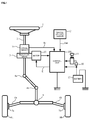
- a column shaft (a steering shaft) 2 connected to a steering wheel (a steering handle) 1, is connected to steered wheels 8L and 8R through reduction gears 3, universal joints 4a and 4b, a rack and pinion mechanism 5, and tie rods 6a and 6b, further via hub units 7a and 7b.
- the column shaft 2 is provided with a torque sensor 10 for detecting a steering torque of the steering wheel 1, and a motor 20 for assisting the steering force of the steering wheel 1 is connected to the column shaft 2 through the reduction gears 3.
- Electric power is supplied to a control unit 100 for controlling the electric power steering apparatus from a battery 13, and an ignition key signal is inputted into the control unit 100 through an ignition key 11. Further, in a vehicle with an idling stop function, the ignition key signal is inputted into the control unit 100 via a voltage stabilization circuit 30 and then through the ignition key 11.
- the control unit 100 calculates a steering assist command value of an assist (steering assist) command based on a steering torque Tr detected by the torque sensor 10 and a vehicle velocity Vel detected by a vehicle velocity sensor 12, and controls a current supplied to the motor 20 based on a current control value E obtained by performing compensation and so on with respect to the steering assist command value. Moreover, it is also possible to receive the vehicle velocity Vel from a CAN (Controller Area Network) and so on.
- CAN Controller Area Network
- the control unit 100 mainly comprises a CPU (or an MPU or an MCU), and general functions performed by programs within the CPU are shown in FIG.2 .
- the steering torque Tr detected by the torque sensor 10 and the vehicle velocity Vel from the vehicle velocity sensor 12 are inputted into a steering assist command value calculating section 101, and a steering assist command value Iref is calculated by means of an assist map.
- the calculated steering assist command value Iref is inputted into a maximum output limiting section 102 and an output is limited based on an overheat protection condition or the like in the maximum output limiting section 102.
- a current command value I that maximum output is limited, is inputted into a subtracting section 103.
- the steering assist command value Iref performed in the steering assist command value calculating section 101, it is also possible to calculate the steering assist command value Iref by using not only the steering torque Tr and the vehicle velocity Vel but also a steering angle.
- the motor current i of the motor 20 is detected by a motor current detecting circuit 107, and the detected motor current i is inputted into the subtracting section 103 to feed back.
- the motor drive circuit 106 comprises an FET gate drive circuit 106A that drives each gate of field-effect transistors (FET1 to FET6) based on the PWM-signal PS from the PWM control section 105, an inverter 106B comprising a three-phase bridge circuit of FET1 to FET6 and a booster circuit 106C that boosts high side FETs (FET1, FET2 and FET3).
- FET1 to FET6 diodes D1 to D6 for surge absorbing are built between their respective sources and their respective drains in anti-parallel.
- each pair of Zener diodes ZD1 to ZD3 for protecting gate is connected between their respective gates and their respective sources.
- the inverter 106B comprises an FET-array that the FET1 and the FET4 are connected in series, an FET-array that the FET2 and the FET5 are connected in series, and an FET-array that the FET3 and the FET6 are connected in series, and these three FET-arrays connected in series are connected in parallel.
- each motor phase current is supplied to the motor 20 through supply routes "a", "b” and "c".
- the battery 13 supplies the electric power to loading apparatuses such as the control unit 100, the torque sensor 10, the motor 20 and so on.
- loading apparatuses such as the control unit 100, the torque sensor 10, the motor 20 and so on.
- the power-source voltage the battery voltage
- a given stable range for example, 10V-15V.
- the power-source voltage reduction occurs.
- Patent Document 1 Japanese Published Unexamined Patent Application No. 2005-193751 A
- Patent Document 2 Japanese Unexamined Patent Application No.
- Patent Document 2 reduces the heating amount by using FETs with a low on-state resistance at a time of low voltage and works even in a low voltage, there is a possibility that the voltage drop occurs in the cranking, the variation is large, when the power-source voltage is less than the operation voltage of the torque sensor, the control become unstable.
- an ignition voltage of an electric power steering apparatus mounted on a vehicle with the idling stop function is compensated by boosting the voltage drop at the time of restart of the engine by means of the voltage stabilization circuit so as to reach a certain voltage, when restarting the engine, a voltage potential difference occurs between the battery voltage and the ignition voltage due to the battery voltage drop.
- a voltage obtained by boosting the ignition voltage by means of the booster circuit 106C is applied to gate terminals of high side the FET1, the FET2 and the FET3, and an inverter applying voltage corresponding to the battery voltage is applied to source terminals of high side the FET1, the FET2 and the FET3.
- the voltage from gate to source becomes large so that the battery voltage drops, and voltages that are applied to the Zener diodes ZD1 to ZD3 for protecting gate connected between gate and source also become large.
- Zener diodes ZD1 to ZD3 When the voltages that are applied to the Zener diodes ZD1 to ZD3 exceed Zener voltage, since the current flows and self-heating occurs, it is necessary to suppress the self-heating by limiting the duty ratio of the PWM-signal and shortening on-state time of high side the FET1, the FET2 and the FET3 or increase rated electric power of the Zener diodes ZD1 to ZD3.
- Patent Document 1 limits assist in accordance with the power-source voltage, there is a problem that it is impossible to effectively suppress the self-heating of the Zener diodes.
- the present invention has been developed in view of the above-described circumstances, and an object of the present invention is to provide an electric power steering apparatus that certainly protects Zener diodes that are built into a drive circuit without increasing the rated electric power of the Zener diodes and further without impairing steering performances by time-integrating a loss power of the Zener diodes and limiting a duty ratio with an increase in an integrating loss even though a power-source voltage varies drastically and drops due to cranking or the like.
- the present invention relates to an electric power steering apparatus that calculates a steering assist command value based on a steering torque and a vehicle velocity, generates a PWM-signal based on said steering assist command value, PWM-drives a motor through an FET bridge circuit having Zener diodes for protecting FETs, and performs an assist control of a steering system by a PWM-drive control of said motor, the above-described object of the present invention is achieved by that comprising: a loss power calculating section that calculates a loss power of said Zener diodes when a difference between an ignition voltage and an inverter applying voltage is equal to or more than a predetermined voltage; an integrating loss calculating section to calculate an integrating loss of said loss power; a permissible loss calculating section to calculate a permissible loss of said Zener diodes based on a temperature; a minimum value selecting section to select a minimum value of a loss difference of said permissible loss and said integrating loss; and a limit value calculating section to calculate
- the above-described object of the present invention is more effectively achieved by that wherein further comprising a rate limiter to limit a rate of said limit value; or wherein after said difference becomes equal to or more than said predetermined voltage, said integrating loss of said integrating loss calculating section is cleared to "0" when a progress time after said difference becomes less than said predetermined voltage becomes a predetermined time; or wherein said limit value calculating section outputs said limit value with a proportional relation to said minimum value of said loss difference; or wherein as said temperature raises up, an output characteristic gain of said limit value calculating section increases.
- the electric power steering apparatus of the present invention it is possible to realize protecting of the Zener diodes without impairing the steering performances by time-integrating the loss power of the Zener diodes mounted on the inverter of the motor drive circuit and limiting the duty ratio with the increase in the integrating loss and further using a temperature as a parameter even though the power-source voltage (the battery voltage) varies drastically (drops) due to cranking or the like. Since the present invention limits the duty ratio, also it is not necessary to increase the rated electric power of the Zener diodes.
- the present invention removes limiting of the duty ratio by gradually changing, there is also no impairing the steering performances. Moreover, in the case that a progress time after the difference between the ignition voltage and the battery voltage becomes less than the predetermined voltage passes over the predetermined time, since the present invention clears the integrating loss to "0" as a result that the self-heating temperature of the Zener diodes decreased, it is possible to correctly associate the integrating loss with the self-heating temperature.
- an ignition voltage of an electric power steering apparatus mounted on a vehicle with an idling stop function is compensated by boosting a voltage drop at a time of restart of an engine by means of a voltage stabilization circuit so as to reach a certain voltage, when restarting the engine, a voltage potential difference occurs between a battery voltage and an ignition voltage due to the battery voltage drop.
- the voltage obtained by boosting the ignition voltage is applied to gate terminals of high side FETs of a FET bridge circuit that configures an inverter, the inverter applying voltage corresponding to a power-source voltage is applied to source terminals of the high side FETs, the voltage from gate to source becomes large so that the power-source voltage drops, and the voltages that are applied to Zener diodes for protecting gate connected between gate and source also become large.
- the present invention suppresses the self-heating by limiting the duty ratio and shortening an on-state time of the high side FETs when the difference between the ignition voltage and the power-source voltage becomes equal to or more than the predetermined voltage. Therefore, it is not necessary to increase the rated electric power of the Zener diodes, and it is possible to use inexpensive Zener diodes being small in size.
- the present invention removes limiting of the duty ratio by gradually changing so as not to impair the steering performances. Further, in the case that the predetermined time lapsed, since the present invention clears the integrating loss to "0", it is possible to correctly associate the integrating loss with the self-heating temperature.
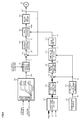
- FIG.4 is a block diagram showing a configuration example of a control unit 100 of an electric power steering apparatus according to the present invention. Since FIG.4 is shown as corresponding to the above-described FIG.2 , with respect to identical configurations (members), identical reference numerals are given without adding explanations.
- the control unit 100 is newly provided with a loss power calculating section 110 that calculates each-phase loss power Pz of three phases, an integrating loss calculating section 112 that calculate an integrating loss Wz of the each-phase loss power of three phases, a temperature sensor 114 that measures an ambient temperature Tf, a permissible loss calculating section 115 that calculates a permissible loss AL based on the measured temperature Tf, a subtracting section 113 that subtracts the integrating loss Wz from the permissible loss AL, a minimum value selecting section 120 that selects a minimum value LD of a loss difference of the permissible loss AL and the integrating loss Wz from three phases and outputs the minimum value LD of the loss difference, a limit value calculating section 130 that calculates a limit value Lv of the duty ratio based on the selected loss difference LD of the minimum value and the permissible loss AL, and a rate limiter 131 that limits (gradually changes) an addition-subtraction speed (a rate) of the limit value Lv
- the PWM-signal PSm of three phases, the ignition voltage Vb and the inverter applying voltage Vr are inputted into the loss power calculating section 110.
- the loss power calculating section 110 calculates the loss power Pz of each-phase Zener diodes (DZ1 to DZ3) based on the PWM-signal PSm, the ignition voltage Vb and the inverter applying voltage Vr, and outputs the calculated each-phase loss power Pz. Only when a self-heating condition of the Zener diode holds, that is, only when "the ignition voltage Vb - the inverter applying voltage Vr ⁇ a predetermined voltage Vc" holds, the loss power calculating section 110 calculates the loss power Pz and outputs the calculated loss power Pz. When the above-described self-heating condition does not hold, since the loss power Pz does not occur, the loss power calculating section 110 outputs "0".
- the integrating loss calculating section 112 calculates the integrating loss Wz by adding the present current (sampling) loss power Pz and the previous (sampling) loss power Pz(Z -1 ) and subtraction-inputs the integrating loss Wz obtained by calculation into the subtracting section 113. That is to say, the integrating loss calculating section 112 time-integrates the loss power Pz, and calculates the integrating loss Wz of the Zener diodes in accordance with the following Expression 2.
- Wz ⁇ Pz ⁇ ⁇ t where, ⁇ t is a processing time.
- the permissible loss calculating section 115 calculates the permissible loss AL of the Zener diodes depending on the measured temperature Tf. Although the permissible loss of the Zener diodes is determined by the degree of permissible temperature rise, when the ambient temperature changes, since the permissible temperature rise of the Zener diodes also changes, it is necessary to calculate the permissible loss AL depending on the ambient temperature Tf. The calculated permissible loss AL is addition-inputted into the subtracting section 113.
- the subtracting section 113 subtracts the integrating loss Wz (three phases) from the permissible loss AL calculated by the permissible loss calculating section 115, and inputs results of subtraction (loss differences) into the minimum value selecting section 120.
- the minimum value selecting section 120 selects a loss difference of a minimum value among three phases and outputs the selected loss difference of the minimum value as the loss difference LD.
- the rate limiter 131 In removing limiting of the duty ratio, in order to suppress a steering uncomfortable feeling, the rate limiter 131 gradually changes.
- Step S1 When the ignition key 11 of the vehicle is turned on, the ignition voltage Vb is measured and inputted, the inverter applying voltage Vr is measured and inputted, and simultaneously the PWM-signal PSm is inputted (Step S1). Then, determining whether "the ignition voltage Vb - the inverter applying voltage Vr" is equal to or more than the predetermined voltage Vc or not (Step S2), in the case that "the ignition voltage Vb - the inverter applying voltage Vr" is equal to or more than the predetermined voltage Vc, the loss power calculating section 110 calculates the loss power Pz based on the ignition voltage Vb, the inverter applying voltage Vr and the PWM-signal PSm (step S3), and the integrating loss calculating section 112 calculates the integrating loss Wz based on the loss power Pz (Step S10).
- Step S11 the temperature Tf measured by the temperature sensor 114 is inputted (Step S11), the permissible loss calculating section 115 calculates the permissible loss AL based on the temperature Tf (Step S12), and the subtracting section 113 calculates "the permissible loss AL - the integrating loss Wz" with respect to each phase (Step S13).
- the subtraction results of "the permissible loss AL - the integrating loss Wz" are inputted into the minimum value selecting section 120, and the loss difference LD of the minimum value among three phases is selected and outputted (Step S14).
- the selected loss difference LD is inputted into the limit value calculating section 130, and the limit value calculating section 130 calculates the limit value Lv by setting the temperature Tf as a parameter and by using the characteristic proportional to the loss difference LD shown in FIG.5 (Step S15).
- the calculated limit value Lv is gradually changed and processed by the rate limiter 131 (Step S16), and the gradually-changed limit value Lm is inputted into the PWM control section 105 and PWM-controlled.
- Step S2 in the case of determining that "the ignition voltage Vb - the inverter applying voltage Vr" is smaller than the predetermined voltage Vc, a progress time from that point of time is measured (Step S4), when the progress time becomes equal to or more than the predetermined time T 0 (Step S5), the integrating loss Wz of the integrating loss calculating section 112 is cleared to "0" (Step S7), skipping to the above Step S11. Further, in the above Step S5, in the case that the progress time is less than the predetermined time T 0 , "0" is outputted and skipping to the above Step S10 (Step S6).
- FIGs. 7 (A) to 7 (E) show one operating example of the present invention.
- FIG.7(A) shows a changing state of the inverter applying voltage Vr
- FIG.7(B) shows a changing state of "the ignition voltage Vb - the inverter applying voltage Vr" by means of a relation with the predetermined voltage Vc.
- FIG. 7 (C) shows the loss power Pz
- FIG.7 (D) shows the integrating loss Wz
- FIG.7(E) shows the limit value Lm of the duty ratio.
- the inverter applying voltage Vr stops dropping at a certain value (for example, 6V) and gradually shifts to rise after holding the certain value (FIG.(A)).
- a certain value for example, 6V
- the difference "Vb-Vr” stops rising at a certain value as shown in FIG.7(B) , gradually drops after holding the certain value, and finally at a time point t3, the difference "Vb-Vr" becomes the predetermined voltage Vc.
- the limit value calculating section 130 shows the example ( FIG.5 ) of the limit value Lv proportional to the loss difference LD, it is also possible for the limit value calculating section 130 to use a non-linear function characteristic. Furthermore, it is possible to arbitrarily change input timing of the ignition voltage Vb, the inverter applying voltage Vr, the temperature Tf, the steering torque Tr and the vehicle velocity Vel.
Landscapes
- Engineering & Computer Science (AREA)
- Chemical & Material Sciences (AREA)
- Combustion & Propulsion (AREA)
- Transportation (AREA)
- Mechanical Engineering (AREA)
- Steering Control In Accordance With Driving Conditions (AREA)
- Power Steering Mechanism (AREA)
Applications Claiming Priority (1)
| Application Number | Priority Date | Filing Date | Title |
|---|---|---|---|
| PCT/JP2013/057599 WO2014147694A1 (fr) | 2013-03-18 | 2013-03-18 | Dispositif de direction assistée électrique |
Publications (3)
| Publication Number | Publication Date |
|---|---|
| EP2977295A1 true EP2977295A1 (fr) | 2016-01-27 |
| EP2977295A4 EP2977295A4 (fr) | 2016-11-02 |
| EP2977295B1 EP2977295B1 (fr) | 2018-08-08 |
Family
ID=51579434
Family Applications (1)
| Application Number | Title | Priority Date | Filing Date |
|---|---|---|---|
| EP13879032.4A Not-in-force EP2977295B1 (fr) | 2013-03-18 | 2013-03-18 | Dispositif de direction assistée électrique |
Country Status (4)
| Country | Link |
|---|---|
| US (1) | US9604666B2 (fr) |
| EP (1) | EP2977295B1 (fr) |
| CN (1) | CN105163999B (fr) |
| WO (1) | WO2014147694A1 (fr) |
Families Citing this family (6)
| Publication number | Priority date | Publication date | Assignee | Title |
|---|---|---|---|---|
| US9762173B2 (en) * | 2015-07-28 | 2017-09-12 | GM Global Technology Operations LLC | Method and apparatus to control an inverter |
| JP6740777B2 (ja) * | 2016-07-27 | 2020-08-19 | 株式会社デンソー | 電動パワーステアリング装置 |
| DE102018114977A1 (de) | 2018-06-21 | 2019-12-24 | Thyssenkrupp Ag | Schutzvorrichtung für einen Halbleiterschalter eines Elektromotors einer elektromechanischen Kraftfahrzeuglenkung |
| CN112805203B (zh) * | 2019-07-18 | 2022-08-26 | 日本精工株式会社 | 电动助力转向控制装置 |
| JP7767750B2 (ja) * | 2021-06-30 | 2025-11-12 | 富士電機株式会社 | 集積回路、及びパワーモジュール |
| US12473019B2 (en) * | 2022-03-31 | 2025-11-18 | Honda Motor Co., Ltd. | Vehicle control device |
Family Cites Families (19)
| Publication number | Priority date | Publication date | Assignee | Title |
|---|---|---|---|---|
| JPH0386094A (ja) * | 1989-08-30 | 1991-04-11 | Nippon Seiko Kk | 3相y結線dcブラシレスモータ駆動用ドライバ |
| US6002226A (en) * | 1998-06-17 | 1999-12-14 | General Motors Corporation | Brushless DC motor control method and apparatus for reduced commutation noise |
| US6448724B1 (en) * | 1999-10-28 | 2002-09-10 | Delphi Technologies, Inc. | Apparatus and method for commutation noise reduction |
| JP3946991B2 (ja) * | 2001-12-14 | 2007-07-18 | 株式会社ジェイテクト | 電動パワーステアリング装置の制御装置 |
| JP2004080851A (ja) * | 2002-08-09 | 2004-03-11 | Aisin Aw Co Ltd | 駆動用電源装置 |
| JP4042848B2 (ja) * | 2002-11-14 | 2008-02-06 | 株式会社ジェイテクト | 電動式ステアリングの制御装置 |
| JP4266690B2 (ja) * | 2003-04-10 | 2009-05-20 | 三菱電機株式会社 | 電動パワーステアリング装置 |
| KR20060119925A (ko) * | 2003-09-02 | 2006-11-24 | 닛본 세이고 가부시끼가이샤 | 전동 파워 스티어링 장치의 제어 장치 |
| JP4356456B2 (ja) | 2004-01-06 | 2009-11-04 | 日本精工株式会社 | 電動パワーステアリング装置の制御装置 |
| JP4517734B2 (ja) * | 2004-06-03 | 2010-08-04 | 日本精工株式会社 | 電動パワーステアリング装置 |
| JP4501599B2 (ja) * | 2004-09-01 | 2010-07-14 | 株式会社ジェイテクト | 電動パワーステアリング装置 |
| US7163080B2 (en) * | 2005-03-11 | 2007-01-16 | Trw Automotive U.S. Llc | Method and apparatus for detecting a failed temperature sensor in an electric assist steering system |
| EP1886897A4 (fr) * | 2005-05-20 | 2010-03-17 | Nsk Ltd | Contrôleur de dispositif de système de direction de puissance électrique |
| JP2007290429A (ja) | 2006-04-21 | 2007-11-08 | Nsk Ltd | 電動パワーステアリング制御装置 |
| CA2593889C (fr) * | 2006-07-26 | 2011-09-27 | Sumitaka Ogawa | Systeme de protection de moteur |
| JP4641293B2 (ja) | 2006-08-25 | 2011-03-02 | 本田技研工業株式会社 | 鞍乗り型車両の過熱保護装置 |
| CN102224059B (zh) * | 2010-02-17 | 2013-03-20 | 日本精工株式会社 | 电动动力转向装置 |
| JP2012196084A (ja) * | 2011-03-17 | 2012-10-11 | Ricoh Co Ltd | 充電装置、電子機器、及び充電方法 |
| JP5670258B2 (ja) * | 2011-05-31 | 2015-02-18 | 日立オートモティブシステムズ株式会社 | ブラシレスモータの駆動装置 |
-
2013
- 2013-03-18 WO PCT/JP2013/057599 patent/WO2014147694A1/fr not_active Ceased
- 2013-03-18 US US14/777,547 patent/US9604666B2/en not_active Expired - Fee Related
- 2013-03-18 CN CN201380074827.0A patent/CN105163999B/zh not_active Expired - Fee Related
- 2013-03-18 EP EP13879032.4A patent/EP2977295B1/fr not_active Not-in-force
Also Published As
| Publication number | Publication date |
|---|---|
| US20160052541A1 (en) | 2016-02-25 |
| WO2014147694A1 (fr) | 2014-09-25 |
| US9604666B2 (en) | 2017-03-28 |
| CN105163999B (zh) | 2017-05-17 |
| CN105163999A (zh) | 2015-12-16 |
| EP2977295A4 (fr) | 2016-11-02 |
| EP2977295B1 (fr) | 2018-08-08 |
Similar Documents
| Publication | Publication Date | Title |
|---|---|---|
| EP2377744B1 (fr) | Dispositif de direction assistée électrique | |
| EP2977295B1 (fr) | Dispositif de direction assistée électrique | |
| US9407190B2 (en) | Electric power steering apparatus | |
| EP2246239B1 (fr) | Dispositif d'alimentation electrique auxiliaire et dispositif de direction a assistance electrique | |
| EP2559608B1 (fr) | Appareil de commande d'appareil de direction assistée électrique | |
| US7091684B2 (en) | Electric power steering apparatus | |
| US20080004773A1 (en) | Control device for electric power steering apparatus | |
| US20190308657A1 (en) | Motor control unit, electric power steering apparatus equipped with the same, and vehicle | |
| EP2945277A1 (fr) | Dispositif de commande pour moteur multiphase et dispositif de direction a assistance électrique l'utilisant | |
| EP2544365A2 (fr) | Dispositif de commande de moteur | |
| EP3255781B1 (fr) | Dispositif de commande de moteur et dispositif de direction assistée électrique équipé de celui-ci | |
| JP2009113676A (ja) | 電動パワーステアリング装置 | |
| JP5838841B2 (ja) | 電動パワーステアリング装置 | |
| EP3616970A1 (fr) | Appareil de commande de véhicule | |
| US20070068727A1 (en) | Electric power steering control device | |
| JP4779499B2 (ja) | 電動パワーステアリング装置 | |
| CN112805203B (zh) | 电动助力转向控制装置 | |
| JP3839424B2 (ja) | 車両の操舵制御装置 | |
| JP5157511B2 (ja) | 電動パワーステアリング装置 | |
| JP6103079B2 (ja) | 電動パワーステアリング装置 | |
| JP3862223B2 (ja) | 電動パワーステアリング制御装置 |
Legal Events
| Date | Code | Title | Description |
|---|---|---|---|
| PUAI | Public reference made under article 153(3) epc to a published international application that has entered the european phase |
Free format text: ORIGINAL CODE: 0009012 |
|
| 17P | Request for examination filed |
Effective date: 20151012 |
|
| AK | Designated contracting states |
Kind code of ref document: A1 Designated state(s): AL AT BE BG CH CY CZ DE DK EE ES FI FR GB GR HR HU IE IS IT LI LT LU LV MC MK MT NL NO PL PT RO RS SE SI SK SM TR |
|
| AX | Request for extension of the european patent |
Extension state: BA ME |
|
| DAX | Request for extension of the european patent (deleted) | ||
| A4 | Supplementary search report drawn up and despatched |
Effective date: 20161006 |
|
| RIC1 | Information provided on ipc code assigned before grant |
Ipc: B62D 119/00 20060101ALI20160929BHEP Ipc: B62D 5/04 20060101AFI20160929BHEP Ipc: B62D 101/00 20060101ALI20160929BHEP Ipc: B62D 6/00 20060101ALI20160929BHEP |
|
| GRAP | Despatch of communication of intention to grant a patent |
Free format text: ORIGINAL CODE: EPIDOSNIGR1 |
|
| STAA | Information on the status of an ep patent application or granted ep patent |
Free format text: STATUS: GRANT OF PATENT IS INTENDED |
|
| INTG | Intention to grant announced |
Effective date: 20180323 |
|
| GRAS | Grant fee paid |
Free format text: ORIGINAL CODE: EPIDOSNIGR3 |
|
| GRAA | (expected) grant |
Free format text: ORIGINAL CODE: 0009210 |
|
| STAA | Information on the status of an ep patent application or granted ep patent |
Free format text: STATUS: THE PATENT HAS BEEN GRANTED |
|
| AK | Designated contracting states |
Kind code of ref document: B1 Designated state(s): AL AT BE BG CH CY CZ DE DK EE ES FI FR GB GR HR HU IE IS IT LI LT LU LV MC MK MT NL NO PL PT RO RS SE SI SK SM TR |
|
| REG | Reference to a national code |
Ref country code: GB Ref legal event code: FG4D |
|
| REG | Reference to a national code |
Ref country code: CH Ref legal event code: EP Ref country code: AT Ref legal event code: REF Ref document number: 1026645 Country of ref document: AT Kind code of ref document: T Effective date: 20180815 |
|
| REG | Reference to a national code |
Ref country code: IE Ref legal event code: FG4D |
|
| REG | Reference to a national code |
Ref country code: DE Ref legal event code: R096 Ref document number: 602013041870 Country of ref document: DE |
|
| REG | Reference to a national code |
Ref country code: NL Ref legal event code: MP Effective date: 20180808 |
|
| REG | Reference to a national code |
Ref country code: LT Ref legal event code: MG4D |
|
| REG | Reference to a national code |
Ref country code: AT Ref legal event code: MK05 Ref document number: 1026645 Country of ref document: AT Kind code of ref document: T Effective date: 20180808 |
|
| PG25 | Lapsed in a contracting state [announced via postgrant information from national office to epo] |
Ref country code: LT Free format text: LAPSE BECAUSE OF FAILURE TO SUBMIT A TRANSLATION OF THE DESCRIPTION OR TO PAY THE FEE WITHIN THE PRESCRIBED TIME-LIMIT Effective date: 20180808 Ref country code: IS Free format text: LAPSE BECAUSE OF FAILURE TO SUBMIT A TRANSLATION OF THE DESCRIPTION OR TO PAY THE FEE WITHIN THE PRESCRIBED TIME-LIMIT Effective date: 20181208 Ref country code: RS Free format text: LAPSE BECAUSE OF FAILURE TO SUBMIT A TRANSLATION OF THE DESCRIPTION OR TO PAY THE FEE WITHIN THE PRESCRIBED TIME-LIMIT Effective date: 20180808 Ref country code: AT Free format text: LAPSE BECAUSE OF FAILURE TO SUBMIT A TRANSLATION OF THE DESCRIPTION OR TO PAY THE FEE WITHIN THE PRESCRIBED TIME-LIMIT Effective date: 20180808 Ref country code: NL Free format text: LAPSE BECAUSE OF FAILURE TO SUBMIT A TRANSLATION OF THE DESCRIPTION OR TO PAY THE FEE WITHIN THE PRESCRIBED TIME-LIMIT Effective date: 20180808 Ref country code: PL Free format text: LAPSE BECAUSE OF FAILURE TO SUBMIT A TRANSLATION OF THE DESCRIPTION OR TO PAY THE FEE WITHIN THE PRESCRIBED TIME-LIMIT Effective date: 20180808 Ref country code: BG Free format text: LAPSE BECAUSE OF FAILURE TO SUBMIT A TRANSLATION OF THE DESCRIPTION OR TO PAY THE FEE WITHIN THE PRESCRIBED TIME-LIMIT Effective date: 20181108 Ref country code: SE Free format text: LAPSE BECAUSE OF FAILURE TO SUBMIT A TRANSLATION OF THE DESCRIPTION OR TO PAY THE FEE WITHIN THE PRESCRIBED TIME-LIMIT Effective date: 20180808 Ref country code: FI Free format text: LAPSE BECAUSE OF FAILURE TO SUBMIT A TRANSLATION OF THE DESCRIPTION OR TO PAY THE FEE WITHIN THE PRESCRIBED TIME-LIMIT Effective date: 20180808 Ref country code: NO Free format text: LAPSE BECAUSE OF FAILURE TO SUBMIT A TRANSLATION OF THE DESCRIPTION OR TO PAY THE FEE WITHIN THE PRESCRIBED TIME-LIMIT Effective date: 20181108 Ref country code: GR Free format text: LAPSE BECAUSE OF FAILURE TO SUBMIT A TRANSLATION OF THE DESCRIPTION OR TO PAY THE FEE WITHIN THE PRESCRIBED TIME-LIMIT Effective date: 20181109 |
|
| PG25 | Lapsed in a contracting state [announced via postgrant information from national office to epo] |
Ref country code: HR Free format text: LAPSE BECAUSE OF FAILURE TO SUBMIT A TRANSLATION OF THE DESCRIPTION OR TO PAY THE FEE WITHIN THE PRESCRIBED TIME-LIMIT Effective date: 20180808 Ref country code: AL Free format text: LAPSE BECAUSE OF FAILURE TO SUBMIT A TRANSLATION OF THE DESCRIPTION OR TO PAY THE FEE WITHIN THE PRESCRIBED TIME-LIMIT Effective date: 20180808 Ref country code: LV Free format text: LAPSE BECAUSE OF FAILURE TO SUBMIT A TRANSLATION OF THE DESCRIPTION OR TO PAY THE FEE WITHIN THE PRESCRIBED TIME-LIMIT Effective date: 20180808 |
|
| PG25 | Lapsed in a contracting state [announced via postgrant information from national office to epo] |
Ref country code: EE Free format text: LAPSE BECAUSE OF FAILURE TO SUBMIT A TRANSLATION OF THE DESCRIPTION OR TO PAY THE FEE WITHIN THE PRESCRIBED TIME-LIMIT Effective date: 20180808 Ref country code: RO Free format text: LAPSE BECAUSE OF FAILURE TO SUBMIT A TRANSLATION OF THE DESCRIPTION OR TO PAY THE FEE WITHIN THE PRESCRIBED TIME-LIMIT Effective date: 20180808 Ref country code: IT Free format text: LAPSE BECAUSE OF FAILURE TO SUBMIT A TRANSLATION OF THE DESCRIPTION OR TO PAY THE FEE WITHIN THE PRESCRIBED TIME-LIMIT Effective date: 20180808 Ref country code: CZ Free format text: LAPSE BECAUSE OF FAILURE TO SUBMIT A TRANSLATION OF THE DESCRIPTION OR TO PAY THE FEE WITHIN THE PRESCRIBED TIME-LIMIT Effective date: 20180808 Ref country code: ES Free format text: LAPSE BECAUSE OF FAILURE TO SUBMIT A TRANSLATION OF THE DESCRIPTION OR TO PAY THE FEE WITHIN THE PRESCRIBED TIME-LIMIT Effective date: 20180808 |
|
| REG | Reference to a national code |
Ref country code: DE Ref legal event code: R097 Ref document number: 602013041870 Country of ref document: DE |
|
| PG25 | Lapsed in a contracting state [announced via postgrant information from national office to epo] |
Ref country code: SM Free format text: LAPSE BECAUSE OF FAILURE TO SUBMIT A TRANSLATION OF THE DESCRIPTION OR TO PAY THE FEE WITHIN THE PRESCRIBED TIME-LIMIT Effective date: 20180808 Ref country code: SK Free format text: LAPSE BECAUSE OF FAILURE TO SUBMIT A TRANSLATION OF THE DESCRIPTION OR TO PAY THE FEE WITHIN THE PRESCRIBED TIME-LIMIT Effective date: 20180808 Ref country code: DK Free format text: LAPSE BECAUSE OF FAILURE TO SUBMIT A TRANSLATION OF THE DESCRIPTION OR TO PAY THE FEE WITHIN THE PRESCRIBED TIME-LIMIT Effective date: 20180808 |
|
| PLBE | No opposition filed within time limit |
Free format text: ORIGINAL CODE: 0009261 |
|
| STAA | Information on the status of an ep patent application or granted ep patent |
Free format text: STATUS: NO OPPOSITION FILED WITHIN TIME LIMIT |
|
| 26N | No opposition filed |
Effective date: 20190509 |
|
| PG25 | Lapsed in a contracting state [announced via postgrant information from national office to epo] |
Ref country code: SI Free format text: LAPSE BECAUSE OF FAILURE TO SUBMIT A TRANSLATION OF THE DESCRIPTION OR TO PAY THE FEE WITHIN THE PRESCRIBED TIME-LIMIT Effective date: 20180808 |
|
| PG25 | Lapsed in a contracting state [announced via postgrant information from national office to epo] |
Ref country code: MC Free format text: LAPSE BECAUSE OF FAILURE TO SUBMIT A TRANSLATION OF THE DESCRIPTION OR TO PAY THE FEE WITHIN THE PRESCRIBED TIME-LIMIT Effective date: 20180808 |
|
| REG | Reference to a national code |
Ref country code: CH Ref legal event code: PL |
|
| GBPC | Gb: european patent ceased through non-payment of renewal fee |
Effective date: 20190318 |
|
| PG25 | Lapsed in a contracting state [announced via postgrant information from national office to epo] |
Ref country code: LU Free format text: LAPSE BECAUSE OF NON-PAYMENT OF DUE FEES Effective date: 20190318 |
|
| REG | Reference to a national code |
Ref country code: BE Ref legal event code: MM Effective date: 20190331 |
|
| PG25 | Lapsed in a contracting state [announced via postgrant information from national office to epo] |
Ref country code: CH Free format text: LAPSE BECAUSE OF NON-PAYMENT OF DUE FEES Effective date: 20190331 Ref country code: IE Free format text: LAPSE BECAUSE OF NON-PAYMENT OF DUE FEES Effective date: 20190318 Ref country code: GB Free format text: LAPSE BECAUSE OF NON-PAYMENT OF DUE FEES Effective date: 20190318 Ref country code: LI Free format text: LAPSE BECAUSE OF NON-PAYMENT OF DUE FEES Effective date: 20190331 |
|
| PG25 | Lapsed in a contracting state [announced via postgrant information from national office to epo] |
Ref country code: BE Free format text: LAPSE BECAUSE OF NON-PAYMENT OF DUE FEES Effective date: 20190331 |
|
| PG25 | Lapsed in a contracting state [announced via postgrant information from national office to epo] |
Ref country code: TR Free format text: LAPSE BECAUSE OF FAILURE TO SUBMIT A TRANSLATION OF THE DESCRIPTION OR TO PAY THE FEE WITHIN THE PRESCRIBED TIME-LIMIT Effective date: 20180808 |
|
| PG25 | Lapsed in a contracting state [announced via postgrant information from national office to epo] |
Ref country code: MT Free format text: LAPSE BECAUSE OF NON-PAYMENT OF DUE FEES Effective date: 20190318 Ref country code: PT Free format text: LAPSE BECAUSE OF FAILURE TO SUBMIT A TRANSLATION OF THE DESCRIPTION OR TO PAY THE FEE WITHIN THE PRESCRIBED TIME-LIMIT Effective date: 20181208 |
|
| PGFP | Annual fee paid to national office [announced via postgrant information from national office to epo] |
Ref country code: FR Payment date: 20200214 Year of fee payment: 8 |
|
| PG25 | Lapsed in a contracting state [announced via postgrant information from national office to epo] |
Ref country code: CY Free format text: LAPSE BECAUSE OF FAILURE TO SUBMIT A TRANSLATION OF THE DESCRIPTION OR TO PAY THE FEE WITHIN THE PRESCRIBED TIME-LIMIT Effective date: 20180808 |
|
| PGFP | Annual fee paid to national office [announced via postgrant information from national office to epo] |
Ref country code: DE Payment date: 20210302 Year of fee payment: 9 |
|
| PG25 | Lapsed in a contracting state [announced via postgrant information from national office to epo] |
Ref country code: HU Free format text: LAPSE BECAUSE OF FAILURE TO SUBMIT A TRANSLATION OF THE DESCRIPTION OR TO PAY THE FEE WITHIN THE PRESCRIBED TIME-LIMIT; INVALID AB INITIO Effective date: 20130318 |
|
| PG25 | Lapsed in a contracting state [announced via postgrant information from national office to epo] |
Ref country code: FR Free format text: LAPSE BECAUSE OF NON-PAYMENT OF DUE FEES Effective date: 20210331 |
|
| PG25 | Lapsed in a contracting state [announced via postgrant information from national office to epo] |
Ref country code: MK Free format text: LAPSE BECAUSE OF FAILURE TO SUBMIT A TRANSLATION OF THE DESCRIPTION OR TO PAY THE FEE WITHIN THE PRESCRIBED TIME-LIMIT Effective date: 20180808 |
|
| REG | Reference to a national code |
Ref country code: DE Ref legal event code: R119 Ref document number: 602013041870 Country of ref document: DE |
|
| PG25 | Lapsed in a contracting state [announced via postgrant information from national office to epo] |
Ref country code: DE Free format text: LAPSE BECAUSE OF NON-PAYMENT OF DUE FEES Effective date: 20221001 |