EP2977308A1 - System aus schwimmenden Plattformen, und Lastkahn zum Eingreifen - Google Patents
System aus schwimmenden Plattformen, und Lastkahn zum Eingreifen Download PDFInfo
- Publication number
- EP2977308A1 EP2977308A1 EP14178603.8A EP14178603A EP2977308A1 EP 2977308 A1 EP2977308 A1 EP 2977308A1 EP 14178603 A EP14178603 A EP 14178603A EP 2977308 A1 EP2977308 A1 EP 2977308A1
- Authority
- EP
- European Patent Office
- Prior art keywords
- barge
- platform
- compartment
- float
- floating
- Prior art date
- Legal status (The legal status is an assumption and is not a legal conclusion. Google has not performed a legal analysis and makes no representation as to the accuracy of the status listed.)
- Withdrawn
Links
- 238000007667 floating Methods 0.000 title claims abstract description 32
- 238000007654 immersion Methods 0.000 claims abstract description 25
- 238000012546 transfer Methods 0.000 claims abstract description 11
- 230000000295 complement effect Effects 0.000 claims description 21
- 238000000034 method Methods 0.000 claims description 11
- XLYOFNOQVPJJNP-UHFFFAOYSA-N water Substances O XLYOFNOQVPJJNP-UHFFFAOYSA-N 0.000 claims description 10
- 229910001868 water Inorganic materials 0.000 claims description 10
- 230000000694 effects Effects 0.000 claims description 8
- 238000000605 extraction Methods 0.000 claims description 7
- 238000002347 injection Methods 0.000 claims description 4
- 239000007924 injection Substances 0.000 claims description 4
- 238000010010 raising Methods 0.000 claims description 4
- 238000005086 pumping Methods 0.000 claims description 3
- 238000005070 sampling Methods 0.000 claims description 3
- 238000010276 construction Methods 0.000 description 3
- 239000000463 material Substances 0.000 description 3
- 238000003032 molecular docking Methods 0.000 description 3
- 238000013459 approach Methods 0.000 description 2
- 238000012550 audit Methods 0.000 description 2
- 238000003780 insertion Methods 0.000 description 2
- 230000037431 insertion Effects 0.000 description 2
- 230000000670 limiting effect Effects 0.000 description 2
- 239000002184 metal Substances 0.000 description 2
- 229910052751 metal Inorganic materials 0.000 description 2
- 229920003023 plastic Polymers 0.000 description 2
- 239000004033 plastic Substances 0.000 description 2
- 230000008569 process Effects 0.000 description 2
- 230000008439 repair process Effects 0.000 description 2
- 230000001010 compromised effect Effects 0.000 description 1
- 238000005260 corrosion Methods 0.000 description 1
- 230000007797 corrosion Effects 0.000 description 1
- 230000008878 coupling Effects 0.000 description 1
- 238000010168 coupling process Methods 0.000 description 1
- 238000005859 coupling reaction Methods 0.000 description 1
- 238000013461 design Methods 0.000 description 1
- 238000011161 development Methods 0.000 description 1
- 238000011049 filling Methods 0.000 description 1
- 238000011065 in-situ storage Methods 0.000 description 1
- 238000012966 insertion method Methods 0.000 description 1
- 238000012423 maintenance Methods 0.000 description 1
- 230000036961 partial effect Effects 0.000 description 1
- 238000011084 recovery Methods 0.000 description 1
- 238000007789 sealing Methods 0.000 description 1
Images


Classifications
-
- B—PERFORMING OPERATIONS; TRANSPORTING
- B63—SHIPS OR OTHER WATERBORNE VESSELS; RELATED EQUIPMENT
- B63B—SHIPS OR OTHER WATERBORNE VESSELS; EQUIPMENT FOR SHIPPING
- B63B27/00—Arrangement of ship-based loading or unloading equipment for cargo or passengers
- B63B27/36—Arrangement of ship-based loading or unloading equipment for floating cargo
-
- B—PERFORMING OPERATIONS; TRANSPORTING
- B63—SHIPS OR OTHER WATERBORNE VESSELS; RELATED EQUIPMENT
- B63B—SHIPS OR OTHER WATERBORNE VESSELS; EQUIPMENT FOR SHIPPING
- B63B25/00—Load-accommodating arrangements, e.g. stowing, trimming; Vessels characterised thereby
- B63B25/002—Load-accommodating arrangements, e.g. stowing, trimming; Vessels characterised thereby for goods other than bulk goods
- B63B25/006—Load-accommodating arrangements, e.g. stowing, trimming; Vessels characterised thereby for goods other than bulk goods for floating containers, barges or other floating cargo
-
- B—PERFORMING OPERATIONS; TRANSPORTING
- B63—SHIPS OR OTHER WATERBORNE VESSELS; RELATED EQUIPMENT
- B63B—SHIPS OR OTHER WATERBORNE VESSELS; EQUIPMENT FOR SHIPPING
- B63B35/00—Vessels or similar floating structures specially adapted for specific purposes and not otherwise provided for
- B63B35/34—Pontoons
Definitions
- the invention relates to a system of floating platforms and of intervention barge for the replacement of the floats of said floating platforms.
- the invention relates more particularly to a system of floating platforms and of intervention barge for the replacement of the floats of said floating platforms, said floating platforms each comprising an at least partially immersed platform structure divided into substantially horizontal compartments each of which opens at least at one end of said structure and is capable of receiving at least one partially immersed float.
- Floating platforms of the type described above are commonly used for the development of lakes, ponds, or other types of water in which it is desired to install a foundation-free platform, which can be installed quickly on said body of water.
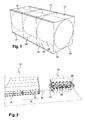
- Such platforms comprise, in known manner, a substantially parallelepipedal tubular structure, of which an emergent part receives, for example, a floor or various installations, and which delimits under these floors or installations a series of partially immersed cage-shaped compartments each receiving a corresponding float. .
- the floats can be made in different ways, especially in plastic materials, but also more generally in the form of tanks or metal cylinders trapped in a parallelepipedal frame of the same substantially rectangular section that the compartments, so as to be introduced horizontally sliding in said compartments or cages.
- the floats are intended to be partially immersed with the platform so as to ensure the lift.
- This intervention is particularly expensive because it requires, especially in the case of large platforms, to have significant lifting means, all the more important that the floats are pierced and / or that they are likely to contain significant amounts of water and that their weight opposes the lifting of the platform.
- the invention overcomes this disadvantage by proposing an intervention barge allowing the replacement of the floats of such floating platforms in situ, these remaining immersed.
- the invention also relates to a method of extracting or inserting a float received in a compartment of a floating platform comprising a substantially longitudinal tubular platform structure which delimits substantially parallelepipedic cages forming the compartments,
- FIG. 2 a system according to the invention comprising an intervention barge 10 for the replacement of floats 12 of a floating platform 14.
- the intervention barge 10 is intended in particular to allow the replacement of floats 12 of floating platforms 14 similar to that which has been shown in FIG. figure 1 .
- the floating platform 14 essentially comprises a platform structure 16 of which at least partially immersed part is divided into compartments 18 of substantially horizontal orientation which open at ends 20 of the structure 16 and which are each likely to receive at least one float 12 partially immersed.
- the intervention barge 10 comprises an at least partially submerged barge structure 20 comprising at least one compartment 22 of dimensions corresponding to those of the compartments 18 of the platform 14 and whose end 24 is able to be closed at the end of the corresponding compartment of the platform 14.
- the intervention barge 10 also comprises means for securing the barge structure 20 to the structure 16 of the platform 18.
- the barge 10 includes a control means (not shown on the figure 2 ) of the immersion level of said barge structure.
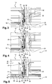
- these means successively allow the stowage of the barge 10 to the platform 14, as shown in FIGS. Figures 3 to 5 and 8 to 10 , the control of the immersion level of the barge 10 with respect to the platform 14 so as to allow the alignment of at least one compartment 22 of the barge 10 with a compartment 18 of the platform, as shown to the figures 5 and 10 , then the transfer of a float 12 from the platform 14 to the barge 10 when it comes to taking a float 12 on a platform 14, or the transfer of a float 12 of the barge 10 to the platform 14 when it comes to replace a float 12 in the platform 14 from which it comes, as shown in the figure 7 .
- the intervention barge 10 is intended to cooperate with a type of platform commonly known current of the type represented by Figures 2 to 10 which comprises a parallelepipedal tubular platform structure 16 of substantially longitudinal orientation in the sense of the longitudinal orientation of the compartments 18, which delimits substantially horizontal parallelepipedic cages forming the compartments 18.
- the barge 10 comprises a barge structure 20 also parallelepipedal tubular, of substantially longitudinal orientation, which delimits at least one sampling chamber 22 substantially horizontal parallelepiped of dimensions corresponding to those of the compartments 18 of the platform 14.
- substantially parallelepipedic cages forming the compartments 18 are thus open at the longitudinal ends of the platform 14 to allow horizontal extraction of the floats 12.
- figure 1 a float 12 intended to be received in a platform 14 of the system according to the invention.
- such a float 12 comprises a central element 28 made in the form of a tank of substantially cylindrical section on which are welded at regular intervals blanks 30 of substantially square section connected by angles 31 whose dimensions correspond to the dimensions of compartments 18, 22, in order to allow the introduction of the float 12 in the compartment 18 by simply sliding on the lower edges 26 of its blanks 30.
- This configuration makes it possible to reduce the points of contact between the central element 28 of the reservoir 12 and the compartment 18, as well as the risks of jamming of said element 28.
- the float 12 could be made of another material, for example in the form of a tank made of plastic material, or be made in a welded mechanical design having another form compatible with the shape of the compartment 18.
- the securing means comprise high coupling means in the vertical direction comprising at least a first high element integral with the platform and at least a second upper element 32 complementary moved by a device 34 of vertical jack carried by the barge 10.
- the securing means also comprise low hooking means in the vertical direction comprising at least a first lower member 36 integral with the platform 14 and at least one second base member 38 integral with the complementary barge 10.
- the upper and lower hooking means successively allow the approach of the barge 10 to the contact of the platform 14 as shown in FIGS. figures 3 and 8 each second high element 32 being arranged under a first high element 30 and each second low element 38 being arranged above a first low element 36.
- the jack device 34 performs a first ascent so as to cause the first and second high elements 30 and 32 to interlock.
- the barge 10 is lowered under the effect of the immersion control means accompanied simultaneously by a second ascent of the jack device 32 so as to maintaining the attachment of the first and second high elements 30 and 32 at the same time as the second lower elements 38 move towards the first lower elements 36 so as to cause them to interlock as shown in FIGS. figure 5 and 10 .
- the barges 10 and platforms 14 are securely locked to one another with their respective compartments 16, 22 arranged facing each other.
- an upper end 40 of the float 12 is arranged in contact with an upper face 42 of the compartment 18.
- the lower end 44 of the float 12 is arranged with a set clearance "J" above a bottom 46 of the compartment 18.
- the means for controlling the immersion level of the barge 10 are provided simply by the jack device 34.
- the jack device 34 is dimensioned so as to be able to move the barge 10 relative to the platform 14 by opposing the buoyancy force acting on the barge 10, as shown in FIG. Figures 4 and 5 .
- This configuration makes it possible in a simple manner to control the level of immersion.
- the means for controlling the immersion level of the barge structure 10 could comprise at least one ballast immersion device of the barge 10.
- the jack device 34 could be dimensioned downwards only to cause the hooking of the first and second high elements 30 and 32 and to accompany the barge 10 as it descends under the effect of the ballast immersion device (not shown), without having to oppose the Archimedean thrust.
- the barge structure 20 has at its end 24 a gantry 50 of substantially vertical and transverse orientation receiving at each of its transverse ends 52 a free end 54 of a body 56 of a jack 58 double effect comprising a rod 60 whose free end 62 is connected to at least a second high element 32 of the platform 10.
- the jack device 34 is movable between a low position, shown in FIGS. figures 3 and 8 corresponding to the deployment of the rods 60 of the jacks 58 out of their body 56 and a high position, shown in FIGS. Figures 5 to 7 and 10 corresponding to the retraction of the rods 60 of the cylinders 58 in their bodies 56 and
- second high elements 32 of the barge 10 comprise upwardly open hooks carried by the ends 62 of the cylinders 58, which are complementary to a transverse bar forming the second elements 30 which extends parallel to an upper edge 21 of the end 20 of the structure 16 of the platform 10, said barge being fixed at regular intervals to said upper edges 21 of the platform 10.
- the second lower members 38 of the barge 10 comprise open hooks which are fixed at regular intervals on a lower edge 25 of the structure 20 of the barge 10, said hooks 38 being complementary to a transverse bar forming the first lower members 36 which extends parallel to a lower edge 23 of the structure 16 of the platform 10, this transverse bar being fixed at regular intervals to said lower edge 23 of the platform structure.
- the fasteners of the bars 30, 36 are preferably made in alignment with the structural elements of the parallelepipedic structure 16 of the platform 14, and the lower hooks forming the elements.
- the bottom 38 of the platform are preferably also arranged in the extension of the structural elements of the structure 20 of the barge 10.
- the second upper element 32 of the barge 10 comprises a transverse bar which extends parallel to a cross member 64 of the gantry 50 and which is fixed to the ends 62 of the jacks 58.
- the bar is fixed at regular intervals to the crossmember 64 via supports and the bar is complementary to hooks forming the first high elements 30 of the platform which are open downwards and which are carried by the upper edge 21 of the structure 16 of the platform 10.
- the second lower members 38 of the barge are shaped as vertical fingers which extend downwards from the ends of associated members 66 which are fixed at regular intervals on a lower edge of the structure 20 of the barge 10.
- these fingers 38 being complementary to corresponding hooks 36 forming the first low elements of the platform, said hooks being open upwards and carried by a lower edge 23 of the structure 16 of the platform.
- the method comprises a first step in which approaching a platform 14 a barge intervention 10 at least partly immersed, then a second step during which the second upper element 32 of the barge 10 is positioned under a first high element 30 of the platform 10 and each second lower element 38 of the barge 10 above a first lower element 36 of the platform -form 14, then a third step during which it performs a first rise of the cylinder device 34 so as to cause the attachment of the first and second high elements 30 and 32, and a fourth step of descent of the barge under the effect of a second recovery actuator device 34 during which it causes the attachment of the first and second lower members 36 and 38.
- the float 12 In the case of a float extraction, the float 12 must then be filled before pouring it into the compartment 18, then in a sixth step which has been shown in FIG. figure 7 , the float 12 is extracted from its compartment 18 of the platform 10 to convey it to the compartment 22 of the barge 10.
- the method comprises a fifth step during which the float 12 is filled to sink it completely. receiving compartment 22 of the barge 10, then a sixth step during which the float 12 is transferred from its compartment 22 of the barge 10 to its compartment 18 of the platform 10, and finally, a seventh step during which float the float 12, in particular by pumping or by air injection so that it can again support the platform 10.
- an eighth step is carried out in which the first to fourth steps are carried out in order and in opposite directions so as to enable the barge 10 to be uncoupled from the platform 14.
- the invention thus makes it possible to ensure in a simple and effective manner the replacement of the floats of the floating platforms without requiring a dry-docking line thereof, which makes it possible to very substantially reduce the maintenance costs.
Landscapes
- Engineering & Computer Science (AREA)
- Chemical & Material Sciences (AREA)
- Combustion & Propulsion (AREA)
- Mechanical Engineering (AREA)
- Ocean & Marine Engineering (AREA)
- Transportation (AREA)
- Earth Drilling (AREA)
Priority Applications (1)
| Application Number | Priority Date | Filing Date | Title |
|---|---|---|---|
| EP14178603.8A EP2977308A1 (de) | 2014-07-25 | 2014-07-25 | System aus schwimmenden Plattformen, und Lastkahn zum Eingreifen |
Applications Claiming Priority (1)
| Application Number | Priority Date | Filing Date | Title |
|---|---|---|---|
| EP14178603.8A EP2977308A1 (de) | 2014-07-25 | 2014-07-25 | System aus schwimmenden Plattformen, und Lastkahn zum Eingreifen |
Publications (1)
| Publication Number | Publication Date |
|---|---|
| EP2977308A1 true EP2977308A1 (de) | 2016-01-27 |
Family
ID=51224828
Family Applications (1)
| Application Number | Title | Priority Date | Filing Date |
|---|---|---|---|
| EP14178603.8A Withdrawn EP2977308A1 (de) | 2014-07-25 | 2014-07-25 | System aus schwimmenden Plattformen, und Lastkahn zum Eingreifen |
Country Status (1)
| Country | Link |
|---|---|
| EP (1) | EP2977308A1 (de) |
Citations (3)
| Publication number | Priority date | Publication date | Assignee | Title |
|---|---|---|---|---|
| US3978807A (en) * | 1974-03-16 | 1976-09-07 | Aktiengesellschaft "Weser" | Offshore station and method of maintaining the same |
| US6901877B1 (en) * | 2003-10-07 | 2005-06-07 | Michael Winnett | Foam block replacement barge |
| US20080190346A1 (en) * | 2007-02-09 | 2008-08-14 | Drew Linden Krehbiel | Method and apparatus for variable floating structures |
-
2014
- 2014-07-25 EP EP14178603.8A patent/EP2977308A1/de not_active Withdrawn
Patent Citations (3)
| Publication number | Priority date | Publication date | Assignee | Title |
|---|---|---|---|---|
| US3978807A (en) * | 1974-03-16 | 1976-09-07 | Aktiengesellschaft "Weser" | Offshore station and method of maintaining the same |
| US6901877B1 (en) * | 2003-10-07 | 2005-06-07 | Michael Winnett | Foam block replacement barge |
| US20080190346A1 (en) * | 2007-02-09 | 2008-08-14 | Drew Linden Krehbiel | Method and apparatus for variable floating structures |
Similar Documents
| Publication | Publication Date | Title |
|---|---|---|
| EP2495162B1 (de) | Transportschiff einer Windkraftanlage an einen Offshore-Standort und Verfahren zu ihrer Aufstellung | |
| FR2583799A1 (fr) | Procede pour installer la superstructure monobloc d'une plate-forme marine sur les piles d'une structure inferieure reposant sur le fond de la mer. | |
| FR2852917A1 (fr) | Receptacle a compartiments etanches et procede de mise en place pour recuperer des effluents polluants d'une epave | |
| WO2005083183A1 (fr) | Structure de transport, d'installation et de demantelement des elements d'une plate-forme petroliere fixe et procedes de mise en oeuvre d'une telle structure. | |
| FR3017595A1 (fr) | Dispositif de levage d'embarcation fluviale ou maritime | |
| EP0942102B1 (de) | Selbsthebende Plattform mit Eintauchbehälter und Verfahren zum Installieren und Heben des Behälters | |
| FR3080357A1 (fr) | Procede et dispositif d'entretien d'une plateforme flottante | |
| EP1675768B1 (de) | Verfahren und vorrichtung zur rückgewinnung von erdöl aus einem auf einem meeresboden angeordneten tank, insbesondere einem wrack | |
| EP2977308A1 (de) | System aus schwimmenden Plattformen, und Lastkahn zum Eingreifen | |
| WO2004087495A2 (fr) | Dispositif et procede de stabilisation et de controle de la descente ou remontee d’une structure lourde entre la surface et le fond de la mer | |
| FR3140065A1 (fr) | Plateforme flottante off-shore pour fabrication, assemblage, maintenance et/ou démontage d’éoliennes flottantes | |
| FR3001435A1 (fr) | "systeme de plates-formes flottantes et de barge d'intervention" | |
| WO2014108631A1 (fr) | Barge flottante submersible | |
| EP3013639B2 (de) | Anlage zum laden und entladen von containern | |
| FR2486561A1 (fr) | Procede de montage en eau relativement peu profonde, ou moyennement profonde, et d'installation sur le site d'exploitation, d'une plate-forme de forage et de production petroliere a embase-poids | |
| FR3119367A1 (fr) | Plateforme flottante, procédés de désassemblage et d’assemblage associés | |
| WO2014009514A2 (fr) | Installation de stockage de gaz comprimés sous l'eau et procédé d'installation correspondant | |
| EP2162371B1 (de) | Ausrüstung mit einer vorrichtung zum empfangen einer struktur zur aufnahme durch ein trägerfahrzeug mit einem greifarm oder einer rampe | |
| FR2645827A1 (fr) | Plate-forme marine formee d'une pluralite d'elements modulaires pour le stockage de produits et pour l'amarrage et le chargement directs des navires, et procede d'installation, de demontage et de reinstallation en un autre endroit de cette plate-forme | |
| WO2016132056A1 (fr) | Structure de support et d'ancrage d'eolienne maritime du type tour treillis et procede de remorquage et depose en mer | |
| EP1797245B1 (de) | Ölbohrvorrichtung für das offene meer und verfahren zu ihrer installierung auf einer ölbohranlage auf dem offenen meer | |
| FR3040410A1 (fr) | Plancher mobile pour piscine et piscine equipee d'un tel plancher | |
| FR2636042A1 (fr) | Porte-barges et conteneurs monte sur des elements submersibles porteurs et propulseurs | |
| FR2506716A1 (fr) | Installation pour la mise a l'eau, ou hors d'eau, d'un navire | |
| EP0097069B1 (de) | Verfahren zum Installieren einer Plattform im Meer, Plattformüberbau zum Ausführen dieses Verfahrens |
Legal Events
| Date | Code | Title | Description |
|---|---|---|---|
| PUAI | Public reference made under article 153(3) epc to a published international application that has entered the european phase |
Free format text: ORIGINAL CODE: 0009012 |
|
| AK | Designated contracting states |
Kind code of ref document: A1 Designated state(s): AL AT BE BG CH CY CZ DE DK EE ES FI FR GB GR HR HU IE IS IT LI LT LU LV MC MK MT NL NO PL PT RO RS SE SI SK SM TR |
|
| AX | Request for extension of the european patent |
Extension state: BA ME |
|
| STAA | Information on the status of an ep patent application or granted ep patent |
Free format text: STATUS: THE APPLICATION IS DEEMED TO BE WITHDRAWN |
|
| 18D | Application deemed to be withdrawn |
Effective date: 20160728 |