EP2977317B1 - Überwachungssystem zur wartung eines pitch-trimm-aktuators - Google Patents
Überwachungssystem zur wartung eines pitch-trimm-aktuators Download PDFInfo
- Publication number
- EP2977317B1 EP2977317B1 EP15177984.0A EP15177984A EP2977317B1 EP 2977317 B1 EP2977317 B1 EP 2977317B1 EP 15177984 A EP15177984 A EP 15177984A EP 2977317 B1 EP2977317 B1 EP 2977317B1
- Authority
- EP
- European Patent Office
- Prior art keywords
- gas
- oil
- landing
- temperature
- pressure
- Prior art date
- Legal status (The legal status is an assumption and is not a legal conclusion. Google has not performed a legal analysis and makes no representation as to the accuracy of the status listed.)
- Active
Links
Images




Classifications
-
- B—PERFORMING OPERATIONS; TRANSPORTING
- B64—AIRCRAFT; AVIATION; COSMONAUTICS
- B64C—AEROPLANES; HELICOPTERS
- B64C25/00—Alighting gear
- B64C25/32—Alighting gear characterised by elements which contact the ground or similar surface
- B64C25/58—Arrangements or adaptations of shock-absorbers or springs
- B64C25/60—Oleo legs
-
- G—PHYSICS
- G07—CHECKING-DEVICES
- G07C—TIME OR ATTENDANCE REGISTERS; REGISTERING OR INDICATING THE WORKING OF MACHINES; GENERATING RANDOM NUMBERS; VOTING OR LOTTERY APPARATUS; ARRANGEMENTS, SYSTEMS OR APPARATUS FOR CHECKING NOT PROVIDED FOR ELSEWHERE
- G07C5/00—Registering or indicating the working of vehicles
- G07C5/08—Registering or indicating performance data other than driving, working, idle, or waiting time, with or without registering driving, working, idle or waiting time
- G07C5/0808—Diagnosing performance data
-
- B—PERFORMING OPERATIONS; TRANSPORTING
- B64—AIRCRAFT; AVIATION; COSMONAUTICS
- B64D—EQUIPMENT FOR FITTING IN OR TO AIRCRAFT; FLIGHT SUITS; PARACHUTES; ARRANGEMENT OR MOUNTING OF POWER PLANTS OR PROPULSION TRANSMISSIONS IN AIRCRAFT
- B64D45/00—Aircraft indicators or protectors not otherwise provided for
-
- F—MECHANICAL ENGINEERING; LIGHTING; HEATING; WEAPONS; BLASTING
- F15—FLUID-PRESSURE ACTUATORS; HYDRAULICS OR PNEUMATICS IN GENERAL
- F15B—SYSTEMS ACTING BY MEANS OF FLUIDS IN GENERAL; FLUID-PRESSURE ACTUATORS, e.g. SERVOMOTORS; DETAILS OF FLUID-PRESSURE SYSTEMS, NOT OTHERWISE PROVIDED FOR
- F15B1/00—Installations or systems with accumulators; Supply reservoir or sump assemblies
- F15B1/02—Installations or systems with accumulators
- F15B1/04—Accumulators
- F15B1/08—Accumulators using a gas cushion; Gas charging devices; Indicators or floats therefor
- F15B1/24—Accumulators using a gas cushion; Gas charging devices; Indicators or floats therefor with rigid separating means, e.g. pistons
-
- F—MECHANICAL ENGINEERING; LIGHTING; HEATING; WEAPONS; BLASTING
- F15—FLUID-PRESSURE ACTUATORS; HYDRAULICS OR PNEUMATICS IN GENERAL
- F15B—SYSTEMS ACTING BY MEANS OF FLUIDS IN GENERAL; FLUID-PRESSURE ACTUATORS, e.g. SERVOMOTORS; DETAILS OF FLUID-PRESSURE SYSTEMS, NOT OTHERWISE PROVIDED FOR
- F15B19/00—Testing; Calibrating; Fault detection or monitoring; Simulation or modelling of fluid-pressure systems or apparatus not otherwise provided for
- F15B19/005—Fault detection or monitoring
-
- B—PERFORMING OPERATIONS; TRANSPORTING
- B64—AIRCRAFT; AVIATION; COSMONAUTICS
- B64D—EQUIPMENT FOR FITTING IN OR TO AIRCRAFT; FLIGHT SUITS; PARACHUTES; ARRANGEMENT OR MOUNTING OF POWER PLANTS OR PROPULSION TRANSMISSIONS IN AIRCRAFT
- B64D45/00—Aircraft indicators or protectors not otherwise provided for
- B64D2045/0085—Devices for aircraft health monitoring, e.g. monitoring flutter or vibration
-
- F—MECHANICAL ENGINEERING; LIGHTING; HEATING; WEAPONS; BLASTING
- F15—FLUID-PRESSURE ACTUATORS; HYDRAULICS OR PNEUMATICS IN GENERAL
- F15B—SYSTEMS ACTING BY MEANS OF FLUIDS IN GENERAL; FLUID-PRESSURE ACTUATORS, e.g. SERVOMOTORS; DETAILS OF FLUID-PRESSURE SYSTEMS, NOT OTHERWISE PROVIDED FOR
- F15B20/00—Safety arrangements for fluid actuator systems; Applications of safety devices in fluid actuator systems; Emergency measures for fluid actuator systems
- F15B20/005—Leakage; Spillage; Hose burst
-
- F—MECHANICAL ENGINEERING; LIGHTING; HEATING; WEAPONS; BLASTING
- F15—FLUID-PRESSURE ACTUATORS; HYDRAULICS OR PNEUMATICS IN GENERAL
- F15B—SYSTEMS ACTING BY MEANS OF FLUIDS IN GENERAL; FLUID-PRESSURE ACTUATORS, e.g. SERVOMOTORS; DETAILS OF FLUID-PRESSURE SYSTEMS, NOT OTHERWISE PROVIDED FOR
- F15B2201/00—Accumulators
- F15B2201/50—Monitoring, detection and testing means for accumulators
-
- F—MECHANICAL ENGINEERING; LIGHTING; HEATING; WEAPONS; BLASTING
- F15—FLUID-PRESSURE ACTUATORS; HYDRAULICS OR PNEUMATICS IN GENERAL
- F15B—SYSTEMS ACTING BY MEANS OF FLUIDS IN GENERAL; FLUID-PRESSURE ACTUATORS, e.g. SERVOMOTORS; DETAILS OF FLUID-PRESSURE SYSTEMS, NOT OTHERWISE PROVIDED FOR
- F15B2201/00—Accumulators
- F15B2201/50—Monitoring, detection and testing means for accumulators
- F15B2201/51—Pressure detection
-
- F—MECHANICAL ENGINEERING; LIGHTING; HEATING; WEAPONS; BLASTING
- F15—FLUID-PRESSURE ACTUATORS; HYDRAULICS OR PNEUMATICS IN GENERAL
- F15B—SYSTEMS ACTING BY MEANS OF FLUIDS IN GENERAL; FLUID-PRESSURE ACTUATORS, e.g. SERVOMOTORS; DETAILS OF FLUID-PRESSURE SYSTEMS, NOT OTHERWISE PROVIDED FOR
- F15B2201/00—Accumulators
- F15B2201/50—Monitoring, detection and testing means for accumulators
- F15B2201/515—Position detection for separating means
-
- F—MECHANICAL ENGINEERING; LIGHTING; HEATING; WEAPONS; BLASTING
- F15—FLUID-PRESSURE ACTUATORS; HYDRAULICS OR PNEUMATICS IN GENERAL
- F15B—SYSTEMS ACTING BY MEANS OF FLUIDS IN GENERAL; FLUID-PRESSURE ACTUATORS, e.g. SERVOMOTORS; DETAILS OF FLUID-PRESSURE SYSTEMS, NOT OTHERWISE PROVIDED FOR
- F15B2211/00—Circuits for servomotor systems
- F15B2211/60—Circuit components or control therefor
- F15B2211/625—Accumulators
-
- F—MECHANICAL ENGINEERING; LIGHTING; HEATING; WEAPONS; BLASTING
- F15—FLUID-PRESSURE ACTUATORS; HYDRAULICS OR PNEUMATICS IN GENERAL
- F15B—SYSTEMS ACTING BY MEANS OF FLUIDS IN GENERAL; FLUID-PRESSURE ACTUATORS, e.g. SERVOMOTORS; DETAILS OF FLUID-PRESSURE SYSTEMS, NOT OTHERWISE PROVIDED FOR
- F15B2211/00—Circuits for servomotor systems
- F15B2211/70—Output members, e.g. hydraulic motors or cylinders or control therefor
- F15B2211/705—Output members, e.g. hydraulic motors or cylinders or control therefor characterised by the type of output members or actuators
- F15B2211/7051—Linear output members
- F15B2211/7053—Double-acting output members
- F15B2211/7054—Having equal piston areas
-
- F—MECHANICAL ENGINEERING; LIGHTING; HEATING; WEAPONS; BLASTING
- F15—FLUID-PRESSURE ACTUATORS; HYDRAULICS OR PNEUMATICS IN GENERAL
- F15B—SYSTEMS ACTING BY MEANS OF FLUIDS IN GENERAL; FLUID-PRESSURE ACTUATORS, e.g. SERVOMOTORS; DETAILS OF FLUID-PRESSURE SYSTEMS, NOT OTHERWISE PROVIDED FOR
- F15B2211/00—Circuits for servomotor systems
- F15B2211/80—Other types of control related to particular problems or conditions
- F15B2211/857—Monitoring of fluid pressure systems
Definitions
- the present disclosure relates to landing gear, and more particularly, to systems and methods for monitoring the service requirements of a pitch trim actuator.
- the prior art dealing with the monitoring of the fluid levels in oleopneumatic devices is illustrated by document US 2012/0053783 A1 .
- Landing gear supports an aircraft while the aircraft is on the ground.
- Some landing gear may include a bogie beam which supports one or more pairs of wheels.
- the bogie beam may pivot relative to the landing gear.
- a pitch trim actuator may orient the bogie beam to a flight position during landing gear retraction and extension.
- a method for determining a status of fluids within an oleopneumatic pitch trim actuator of an aircraft landing gear is claimed in claim 1.
- FIG. 1 a portion of a landing gear is illustrated in a deployed position, according to various embodiments.
- Landing gear may comprise strut 2 and bogie beam 4.
- Bogie beam 4 may support one or more axles.
- the one or more axles may have one or more wheels mounted for rotation. In that regard, when on the ground, the weight of the aircraft is transferred through the landing gear to the one or more axles and finally to the one or more wheels.
- Pitch trim actuator 100 has a first terminus 111 (as illustrated in FIG. 2A ) and a second terminus 113 (as also illustrated in FIG. 2B ).
- Pitch trim actuator 100 comprises pitch trim actuator piston 101 and pitch trim actuator housing 103.
- Pitch trim actuator piston 101 is configured to translate within pitch trim actuator housing 103.
- a hydraulic system may be disposed within pitch trim actuator 100 to damp relative translational motion between pitch trim actuator piston 101 and pitch trim actuator housing 103.
- Pitch trim actuator 100 may orient bogie beam 4 to the flight position during gear retraction and extension, as well as any other time in which the aircraft is airborn (between take-off and touchdown).
- Pitch trim actuator 100 may also assist in damping the oscillation of bogie beam 4 relative to strut 2.
- the first terminus 111 of pitch trim actuator 100 may comprise a portion of pitch trim actuator piston 101.
- the first terminus 111 of pitch trim actuator 100 is coupled to a pivot joint 10 of bogie beam 4, with momentary reference to FIG. 1 .
- the second terminus 113 of pitch trim actuator 100 may comprise a portion of pitch trim actuator housing 103.
- the second terminus 113 of pitch trim actuator 100 may be coupled to strut 2, with momentary reference to FIG. 1 .
- the first terminus 111 of pitch trim actuator 100 may be coupled to strut 2 and the second terminus 113 of pitch trim actuator 100 may be coupled to pivot joint 10.
- pitch trim actuator 100 may be positioned elsewhere in relation to strut 2 and bogie beam 2.
- pitch trim actuator 100 While the discussion herein is directed to pitch trim actuator 100, it will be obvious to one skilled in the art that the systems and methods described herein are applicable to many types of actuators and shocks and struts. Therefore, the disclosure herein is not limited to applications solely directed to pitch trim actuator 100.
- FIG. 2A illustrates a cross section of pitch trim actuator 100.
- Pitch trim actuator 100 includes a main actuator 102 and an accumulator 109.
- Pitch trim actuator 100 includes pitch trim actuator piston 101 and pitch trim actuator housing 103.
- Pitch trim actuator 100 includes a gas chamber 106 positioned entirely in accumulator 109.
- Gas chamber 106 may include a gas, such as air or nitrogen gas.
- Pitch trim actuator 100 includes an oil chamber 108 positioned within main actuator 102 and accumulator 109. Oil chamber 108 is continuous within main actuator 102 and accumulator 109, and thus main actuator 102 is in fluid communication with accumulator 109 via oil chamber 108.
- Oil chamber 108 may include hydraulic fluid, such as oil.
- a separator piston 104 is positioned between gas chamber 106 and oil chamber 108.
- Separator piston 104 may float between mechanical stop 105 and mechanical stop 107. Separator piston 104 separates oil chamber 108 from gas chamber 106. Because separator piston 104 floats, volume of gas chamber 106 and oil chamber 108 are dependent upon position of separator piston 104.
- a temperature/pressure sensor 124 may be positioned within oil chamber 108. Temperature/pressure sensor 124 may refer to a single sensor that is adapted to determine the temperature and pressure of oil within oil chamber 108. In various embodiments, temperature/pressure sensor 124 may include a separate temperature sensor and a separate pressure sensor.
- a temperature/pressure sensor 128 may be positioned within gas chamber 106. Temperature/pressure sensor 128 may refer to a single sensor that is adapted to determine the temperature and pressure of gas within gas chamber 106. In various embodiments, temperature/pressure sensor 128 may include a separate temperature sensor and a separate pressure sensor.
- a position sensor 126 may be positioned within gas chamber 106 and/or within oil chamber 108. Position sensor 126 may be able to determine the position of separator piston 104 relative to accumulator 109 (i.e., the stroke). The position of separator piston 104 may be used to determine a volume of gas chamber 106 and/or oil chamber 108. This is because the total volume of gas chamber 106 and oil chamber 108 is known. By knowing the position of separator position, the volume of gas chamber 106 can be determined. Because the total volume is known, and the volume of the gas chamber 106 is determinable, the volume of oil chamber 108 is also determinable
- oil and/or gas may leak from pitch trim actuator 100.
- the pressure of the gas and volume of the oil should be within predetermined ranges for pitch trim actuator 100 to function properly.
- the leakage of oil and/or gas could cause the pressure of the gas and the volume of the oil to fall outside of the predetermined acceptable range of pressures and volumes.
- first seal 110 is positioned around separator piston 104.
- the second seal 112 is positioned where actuator piston 101 enters housing 103 of pitch trim actuator 100.
- the third seal 114 is positioned at the end of actuator piston 101 that is within housing 103.
- first seal 110, second seal 112 and/or third seal 114 may be positioned elsewhere in pitch trim actuator 100.
- pitch trim actuator 100 may include greater or fewer seals than illustrated.
- Oil bleed interface 122 allows oil to be removed from oil chamber 108.
- Oil servicing interface 118 allows oil to be added to oil chamber 108.
- the pressure of the gas may be altered by adding or removing gas from gas chamber 106.
- Drain interface 116 exists for draining gas from gas chamber 106.
- Gas servicing interface 116 allows gas to be added to gas chamber 106.
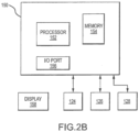
- FIG. 2B illustrates a system 150 for determining fluid levels of pitch trim actuator 100.
- System 150 may be positioned adjacent pitch trim actuator 100 or may be remote from pitch trim actuator 100.
- System 150 includes a processor 152, a memory 154 and an I/O interface 156.
- system 150 may include greater or fewer elements than illustrated in FIG. 2B .
- Processor 152 may be a computer processor such as an ARM processor, DSP processor, distributed processor or other form of central processing. Processor 152 may be adapted to run machine-readable instructions.
- Memory 154 may be a tangible, non-transitory memory and/or a data storage device, such as a hard disk drive, a solid-state disk drive, a hybrid disk drive, or other appropriate data storage. Memory 154 may further store machine-readable instructions which may be loaded and executed by processor 152.
- I/O interface 156 may be any interface capable of allowing data to transfer to and from system 150.
- I/O interface 156 may support a 802.11a/b/g/n/ac signal (e.g., Wi-Fi), a wireless communications protocol using short wavelength UHF radio waves and defined at least in part by IEEE 802.15.1 (e.g., the BLUETOOTH protocol maintained by Bluetooth Special Interest Group), an infrared signal, an optical signal, or any other signal capable of transmitting and receiving information wirelessly to and from I/O interface 156.
- IEEE 802.15.1 e.g., the BLUETOOTH protocol maintained by Bluetooth Special Interest Group
- Display 158 may be any display capable of providing output to a user, such as an LCD display, an OLED display, a touch screen display or the like.
- System 150 may be in logical communication with position sensor 126, temperature/pressure sensor 124 and/or temperature/pressure sensor 128. In that regard, system 150 may send and receive data from position sensor 126, temperature/pressure sensor 124 and/or temperature/pressure sensor 128. Processor 152 may receive data from position sensor 126, temperature/pressure sensor 124, temperature/pressure sensor 128 and/or memory 154. Processor 152 may be adapted to determine the status of oil and gas within pitch trim actuator 100 based on the data received from position sensor 126, temperature/pressure sensor 124, temperature/pressure sensor 128 and/or data stored in memory 154. The status may include oil leakage rates, seal leakage rates, gas leakage rates, estimated number of flight cycles until the next servicing is due and/or current fluid levels of gas and/or oil.
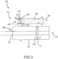
- FIG. 3 illustrates a cross section of pitch trim actuator 100 showing dynamic gas and oil leakage paths.
- a first leakage path 200 may exist around first seal 110 whereby gas exits gas chamber 106 and enters oil chamber 108. If gas leaks via first seal 110 or via a static seal within accumulator 109, no other leakage exists, pressure of the gas in gas chamber 106 will decrease when gas leaks via first leakage path 200. However, the volume of oil will not change because gas that leaks into oil chamber 108 will dissolve in oil and not change the volume of the oil. Gas leakage to the atmosphere also will not change the oil volume. Gas leakage is referred to as gas loss (n gas_loss ).
- a second leakage path 202 may exist around first seal 110. Oil can leak from oil chamber 108 to gas chamber 106 via second leakage path 202. When this happens, the total oil volume within pitch trim actuator 100 remains unchanged. However, gas pressure drops slightly as some gas is dissolved into the leaked oil. Additionally, separator piston 104 moves towards oil chamber 108, and the volume of oil within oil chamber 108 is decreased. Oil leakage via second leakage path 202 is referred to as leaked oil (V oil_leaked ).
- the third leakage path 206 exists between housing 103 and pitch trim actuator piston 101. Oil may be displaced from oil chamber 108 to the atmosphere via third leakage path 206.
- the fourth leakage path 208 exists around the internal end of pitch trim actuator piston 101, such that oil may be displaced from oil chamber 108 into housing 103, which will be considered atmospheric loss.
- oil leaks via third leakage path 206 or fourth leakage path 208 oil volume within oil chamber 108 will reduce.
- separator piston 104 moves towards oil chamber 108. This enlarges the volume of gas chamber 106, allowing gas to expand, resulting in a drop of gas pressure.
- Oil leakage via third leakage path 206 and fourth leakage path 208 is referred to as oil loss (V oil_loss ),
- FIG. 4 illustrates a method 300 for monitoring fluid levels and leakage rates within pitch trim actuator 100.
- Method 300 includes at least three inputs.
- One input is stroke 301, which is the positioning of separator piston 104 within accumulator 109. Stroke 301 may be detected by position sensor 126 on separator piston 104.
- Gas pressure 302 is another input to method 300. Gas pressure 302 may be detected by gas temperature/pressure sensor 128 within gas chamber 106.
- Gas temperature 303 is another input to method 300. Gas temperature 303 may be detected by gas temperature/pressure sensor 128 as well.
- Method 300 includes a recorder module 310, a landing detector module 320, a counter module 330, a fluid level detector module 340, a performance analyzer module 350 and a data logger module 360.
- functions performed by each module may be stored in memory 154 and performed using processor 152. Additionally, inputs and outputs from each module may be stored in memory 154.
- Recorder module 310 receives the inputs to method 300, including stroke 301, gas pressure 302 and gas temperature 303. Recorder module 310 stores these inputs in an array 311 within memory 154 at a desired frequency, such as, for example, between 1 hertz (Hz) and 100Hz. Array 311 is a sliding window containing the most recent 15 seconds of data provided to recorder module 310. The data includes the measured positions of separator piston 104, the gas pressure and the gas temperature measured at periodic intervals. When method 300 initializes, 15 seconds of data are not present. Therefore, for the first 15 seconds after initialization, a detection-state discrete signal 312 indicates that sufficient data is unavailable.
- a detection-state discrete signal 312 indicates that sufficient data is unavailable.
- detection-state discrete signal 312 switches, indicating that 15 seconds of data have been collected.
- array 311 will include the first 15 seconds of data.
- array 311 will include the data between the five second point and the 20 second point.
- method 300 is initiated after the landing gear is deployed and locked and before landing (i.e., while landing gear is deployed and locked and weight is off wheels (WOFFW)). Method 300 remains active for one minute after landing (or weight on wheels (WOW)). It is desired that the inputs to method 300 are continuously recorded between initiation and one minute post WOW at a rate greater than 100 Hz.
- Landing detector module 320 determines the time of WOW. Landing detector module 320 also outputs landing data 322, which includes the data of array 311 at a point in time in which array 311 includes pre-WOW and post-WOW data.
- Landing detector module 320 receives array 311 as input. Landing detector module 320 compares array 311 against certain criteria.
- the first criterion is the separator piston 104 displacement within the recorded 15 sets of data and array 311.
- the specific first criterion is whether the maximum distance from separator piston 104 to one of the mechanical stops ( max (S)) minus the minimum distance from separator piston 104 to one of the mechanical stops ( min (S)) is greater than a tunable parameter ( ⁇ S).
- the first criterion ensures that the set of data is associated with a landing or a takeoff or another event that caused separator piston 104 to become displaced.
- ⁇ S is chosen to be an order of magnitude larger than the possible piston displacement due to temperature variations over a 15 second interval.
- the second criterion is that the separator piston displacement for the first 5 seconds of array 311 is less than a tunable parameter (dS).
- the second criterion ensures that the set of data is associated with a landing event. This is because it ensures that no displacement has been recorded with any first 5 seconds of data in array 311.
- the second criterion also ensures that the chosen set of data includes 5 seconds of steady state measurements before landing.
- the event is categorized as a landing event.
- landing data 322 is provided as an output and a counter-enable signal is provided to counter module 330.
- landing detector module 320 it is desired that landing detector module 320 not provide additional landing data after the initial set of landing data 322 is provided. This is because it allows for a low speed processor to be used for the method 300.
- the counter module 330 ensures this lack of additional landing data from landing detector module 320 for a predetermined period of time. When counter-enable signal 321 is received at counter module 330, counter module 330 sends a counter-state discrete signal 331 to landing detector module 320. While this signal is engaged, landing detector module 320 does not output any more data.
- the predetermined period of time may be five minutes. The predetermined period of time is sufficient for all modules within method 300 to complete their processing.
- Fluid level detector module 340 receives landing data 322 and uses a two-point dynamic check method to determine the levels of oil and gas within pitch trim actuator 100. In order to determine the fluid levels, fluid level detector module 340 makes two assumptions. The first assumption is that transient gas entrainment in the oil that has leaked into accumulator 109 is negligible. The second assumption is that during landing, the gas pressure follows a polytropic compression process with a known polytropic index. The polytropic index can be obtained experimentally. The polytropic index may also change with a compression rate of the oil.
- fluid level detector module 340 oil and gas levels are compared with design values (nominal values) and the oil volume and gas pressure losses are determined.
- Equation 1 is used to estimate the volume of oil leakage into gas chamber 106 via oil chamber 108 for the i th landing event after servicing (via second leakage path 202).
- V oil_leaked_i@ ⁇ gas_i ,1 indicates the oil volume leaked into gas chamber 106 for the i th landing after servicing.
- ⁇ i,1 is the measured separator piston 104 position (stroke) before landing.
- V acc ( ⁇ i,1 ) is the volume of gas chamber 106 at ⁇ i,1 .
- A indicates the area of separator piston 104.
- ⁇ i,2 is the stroke after the landing event.
- P gas_i,2 is the transient gas pressure measured at ⁇ i,2 .
- P gas_i,2 is the measured transient pressure of gas during landing at stroke ⁇ i,2 .
- n may be a known constant value or a known function of compression rate.
- P gas_i, 1 is the measured gas pressure before landing at stroke ⁇ i,1 .
- Equation 2 may be used to determine the external oil leakage through second seal 112 and third seal 114 (via third leakage paths 206 and fourth leakage path 208) for the i th landing after servicing.
- V oil_loss_i@ ⁇ gas _ i, 1 indicates the external oil leakage through the second seal 112 and the third seal 114.
- S( ⁇ gas _ i ,1 ) indicates the displacement of separator piston 104 relative to a reference position.
- the gas loss of pitch trim actuator 100 for the i th landing after servicing may be determined using equation 3.
- n gas _ loss _ i indicates the number of moles of gas lost for the i th landing after servicing.
- P gas , nom indicates nominal gas pressure at the nominal temperature.
- V gas,nom indicates the nominal gas volume at the nominal temperature.
- T nom indicates the nominal temperature.
- R indicates the ideal gas constant.
- Equation 4 may be used to determine oil loss adjusted to the nominal temperature and pressure ( V oil_leaked_i@ ⁇ nom ) for the i th landing after servicing.
- ⁇ represents the oil thermal expansion/contraction coefficient and B represents oil bulk modulus.
- Performance analyzer module 350 receives gas pressure loss 341, oil volume loss 342 and oil volume leakage 343 from fluid level detector module 340 and performs tasks based on these inputs.
- the first task performed by performance analyzer module 350 is verification of servicing of pitch trim actuator 100. This verification of servicing of pitch trim actuator 100 is only performed for the first landing after servicing of pitch trim actuator 100.
- the volume of oil in oil chamber 108 ( V oil@ ⁇ nom ) is determined using equation 7.
- V oil ⁇ 1 @ T nom V oil _ nom ⁇ V oil _ loss _ 1 @ T nom ⁇ V oil _ leaked _ 1 @ T nom
- V oil_nom indicates the nominal oil volume.
- V gas_1@T nom The gas volume in gas chamber 106 (V gas_1@T nom ) is determined using equation 8.
- V gas ⁇ 1 @ T nom V tot ⁇ V oil _ 1 @ T nom ⁇ V oil _ leaked _ 1 @ T nom
- V tot represents the total volume of oil and gas within pitch trim actuator 100.
- P gas _1@T nom The pressure of the gas within gas chamber 106 ( P gas _1@T nom ) can be determined using equation 9.
- P gas _ 1 @ T nom P gas _ nom V gas _ nom ⁇ P gas _ loss _ 1 @ T nom V gas _ nom V gas _ 1 @ T nom
- the total oil volume in pitch trim actuator 100 including oil leaked into gas chamber 106 ( V oil_tot_ 1@ T nom ), may be determined using equation 10.
- V oil _ tot _ 1 @ T nom V oil _ nom ⁇
- V oil _ loss _ 1 @ T nom V oil _ 1 @ T nom + V oil _ leaked _ 1 @ T nom
- the oil volume and gas pressure are compared with a set of predetermined values.
- the volume of the oil in oil chamber 108 is to be greater than a minimum oil volume parameter ( V oil,min,servicing ) and less than a maximum oil volume parameter ( V oil,max,servicing ).
- the minimum and maximum oil volume parameters are predefined and define the operable conditions of oil volume within pitch trim actuator 100.
- the gas pressure in gas chamber 106 is to be greater than a minimum gas pressure parameter ( Pgas , min,servicing ) and less than a maximum gas pressure parameter ( Pgas , max,servicing ).
- the minimum and maximum gas pressure parameters are predetermined parameters that indicate the operable conditions of the gas pressure of pitch trim actuator 100. Equation 11 indicates the relationships discussed above. V oil , min , servicing ⁇ V oil _ 1 @ T nom ⁇ V oil , max , servicing P gas , min , servicing ⁇ P gas _ 1 @ T nom ⁇ P gas , max , servicing
- Performance analyzer module 350 may also determine an average leak rate across first seal 110. Initially after servicing of pitch trim actuator 100, the leakage rate across all seals is expected to be insignificant. In various embodiments, the internal and external leakage rate for the first 100 flight cycles post servicing may not be detectable. Therefore, performance analyzer module 350 devised to apply more weight to the nominal leakage rate of first seal 110 for the first 100 flight cycles. After the first 100 flight cycles post servicing, the leakage volume over the previous 100 flight cycles is used for the determination of the leakage rate.
- the leakage across the first seal 110 ( Q seal #1_ i ) may be determined using equation 12 for the first flight cycle.
- Q seal #1_ nom represents the nominal leakage rate of first seal 110.
- the leakage rate of first seal 110 for flights 2 through 100 post servicing may be calculated using equation 13.
- Q seal # 1 _ i V oil _ leaked _ i @ T nom ⁇ V oil _ leaked _ 1 @ T nom i ⁇ i ⁇ 1 99 + Q seal # 1 , nom 100 ⁇ i 99 for 2 ⁇ i ⁇ 100
- Q seal #1_ i represents the leakage of first seal 110 for the i th landing.
- Equation 14 may be used to determine the leakage across first seal 110 for the i th landing after servicing ( Q seal #1_ i ).
- Q seal # 1 _ i V oil _ leaked _ i @ T nom ⁇ V oil _ leaked _ i ⁇ 100 @ T nom 100 for i > 100
- Equation 15 may be used to determine whether first seal 110 is faulty.
- equation 15 If equation 15 is satisfied, then it may be concluded that first seal 110 is faulty. In equation 15, k is a tunable parameter.
- Performance analyzer module 350 may also determine the average leakage rate across second seal 112 and third seal 114. Equation 16 may be used to determine the average leakage across second seal 112 and third seal 114 for the first landing after servicing.
- Q seal#2&3 _ i represents the oil leakage rate across second seal 112 and third seal 114 and Q seal#2&3,nom indicates the nominal leakage rate across second seal 112 and third seal 114.
- Equation 17 may be used to determine the leakage rate across second seal 112 and third seal 114 for the 2 nd through 100 th landing after servicing.
- Q seal # 2 & 3 _ i V oil _ loss _ i @ T nom ⁇ V oil _ loss _ 1 @ T nom i ⁇ 1 ⁇ i ⁇ 1 99 + Q seal # 2 & 3 , nom 100 ⁇ i 99 for 2 ⁇ i ⁇ 100
- Equation 18 may be used to determine the oil leakage rate across second seal 112 and third seal 114 for each landing beyond the 100 th landing.
- Q seal # 2 & 3 _ i V oil _ loss _ i @ T nom ⁇ V oil _ loss _ i ⁇ 100 @ T nom 100 for i > 100
- the leakage rate across second seal 112 and third seal 114 may be compared to the nominal leakage rate across second seal 112 and third seal 114 ( Q seal#2&3_nom ) to determine whether second seal 112 and/or third seal 114 are faulty.
- Equation 19 illustrates this comparison.
- Equation 19 If Equation 19 is satisfied, second seal 112 and/or third seal 114 are determined to be faulty.
- k is a tunable parameter and may be set to a different value than k in equation 15..
- Equation 22 may be used to determine gas leakage after the first 100 landings post servicing.
- Q gas _ loss _ i P gas _ loss _ i @ T nom ⁇ P gas _ loss _ i ⁇ 100 @ T nom 100
- Equation 23 may be used to determine the remaining oil volume after the i th landing after servicing at the nominal temperature.
- V oil_loss_i@T nom V oil , nom ⁇ V oil _ loss _ i @ T nom ⁇ V oil _ leaked _ i @ T nom
- Equation 24 may be used to determine the volume of gas remaining after the i th landing after servicing at the nominal temperature ( V gas_i@T nom ).
- V gas_i @ T nom V tot ⁇ V oil _ i @ T nom ⁇ V oil _ leaked _ i @ T nom
- Equation 25 may be used to determine the gas pressure after the i th landing after servicing at the nominal temperature ( P gas _ i@T nom ).
- P gas _ i @ T nom P gas , nom V gas , nom ⁇ P gas _ loss _ i @ T nom V gas , nom V gas _ i @ T nom
- Equation 26 may be used to determine the total volume of oil after the i th landing post servicing at the nominal temperature ( V oil_tot_i@T nom ).
- V oil _ tot _ i @ T nom V oil , nom ⁇ V oil , loss _ i @ T nom
- Equation 27 may be used to determine the volume of oil after the i th landing adjusted to -55°C ( V oil_tot_i@ -55 C ).
- V oil_tot_i@ -55 C V oil _ i @ T nom 1 + ⁇ ⁇ 55 ⁇ T nom 1 ⁇ P gas _ i @ ⁇ 55 C ⁇ P gas _ i @ T nom B
- Equation 28 may be used to determine the total volume of oil after the i th landing at -55°C ( V oil_tot_i@- 55 C ).
- V oil_ tot _ i @ ⁇ 55 C V oil _ tot _ i @ T nom 1 + ⁇ ⁇ 55 ⁇ T nom 1 ⁇ P gas _ i @ ⁇ 55 C ⁇ P gas _ i @ T nom B
- Equation 29 may be used to calculate the total gas pressure after the i th landing at -55°C ( P gas_i@- 55 C ).
- P gas_i @ ⁇ 55 C P gas _ i @ T nom V gas _ i @ T nom T nom 273 ⁇ 55 1 V tot ⁇ V oil _ tot _ i @ ⁇ 55 C
- N -1 represents the number of flight cycles remaining until the next servicing.
- N is set to 0.
- the volume of oil at the i+N th landing after servicing adjusted to -55°C V oil _( i+N )@ - 55 C
- the gas pressure at the i+N th landing after servicing adjusted to - 55° P gas_ ( i+N )@-55 C ) is set to the gas pressure after the i th landing adjusted to -55°C.
- V oil _ i + N @ ⁇ 55 C V oil _ i @ T nom ⁇ N ⁇ Q seal # 1 + Q seal # 2,3 1 + ⁇ ⁇ 55 ⁇ T nom 1 ⁇ P gas _ i + N @ ⁇ 55 C ⁇ P gas _ i @ T nom B
- V oil _ tot _ i + N @ ⁇ 55 C V oil _ tot _ i @ T nom ⁇ N ⁇ Q seal # 2,3 1 + ⁇ ⁇ 55 ⁇ T nom 1 ⁇ P gas _ i + N @ ⁇ 55 C ⁇ P gas _ i @ T nom B
- P gas _ i + N @ ⁇ 55 C P gas _ i @ T nom V gas _ i @ T nom T nom ⁇ N ⁇ Q gas ⁇ loss V gas _
- N is incremented by one and equations 30-32 are solved.
- the method 300 stops solving equations 30-32.
- the number of flight cycles to the next servicing is then set to be N- 1. If the number of flight cycles to the next servicing is less than a predetermined threshold, for example, 10, then this information is provided to the maintenance crew for preparation for pitch trim actuator 100 servicing. When N equals 1, servicing is due.
- Data logger module 360 may receive the fluid levels 351, seal leakage rates 352 and remaining number of flight cycles 353 and register them after each landing event. Information saved via data logger module 360 may be available for retrieval from a maintenance system.
- FIG. 5 illustrates a method 400 for determining fluid and gas levels and leakage rates within pitch trim actuator 100.
- Method 400 receives three inputs: stroke 401, gas pressure 402 and gas temperature 403. Stroke 401 may be detected by position sensor 126. Gas pressure 402 and/or gas temperature 403 may be determined by gas temperature/pressure sensor 128.
- Method 400 includes a recorder module 410, a timer module 420, an extension onset detector module 430, a counter module 440, a fluid level detector module 450, a performance analyzer module 460 and a data logger module 470.
- Each of these modules may include an algorithm that is stored in memory 154 and performed by the processor 152. Additionally, inputs and outputs from each module may be stored in memory 154.
- Recorder module 410 operates in the same fashion as recorder module 310 of method 300. The only difference between recorder module 410 and recorder module 310 is that recorder module 410 provides array 411 that includes 5 seconds worth of data that is collected WOFFW instead of 15 seconds of data including WOFFW and WOW data.
- Method 400 is initialized after the landing gear has been deployed for landing and during WOFFW. Method 400 continues to function until WOW occurs. Stroke 401, gas pressure 402 and gas temperature 403 are continuously recorded during this time period at a desired frequency, such as, for example, greater than 100 Hz. Stroke 401, gas pressure 402 and gas temperature 403 are stored in array 411. In various embodiments, method 400 may be applied at any point during WOW.
- detection-state discrete signal 412 indicates that 5 seconds of data has been recorded and array 411 includes a full 5 seconds of data. When this happens, array 411 is provided to extension onset detector module 430. Also, timer module 420 is activated via detection-state discrete signal 412. Timer module 420 may count an amount of time, such as 10 seconds, from receipt of detection-state discrete signal 412.
- Extension onset detector module 430 receives array 411 and computes the average value of stroke 401, gas pressure 402 and gas temperature 403 provided in array 411. Extension onset detector module 430 provides the computed average values (as in-air data 431) of these parameters (in-air data 431) to fluid level detector module 450 in response to timer module 420 finishing its countdown. By waiting for timer module 420 to countdown, it is ensured that measurements within array 411 are taken once pitch trim actuator 100 internal fluids are stabilized for at least the amount of time set within timer module 420 post gear extension.
- Counter module 440 operates the same as counter module 330 in method 300.
- Fluid level detector module 450 uses a one point static check method to determine internal fluid levels of pitch trim actuator 100. Algorithms within fluid level detector module 450 are based on two assumptions. The first assumption is that no gas loss occurs over the entire operation of pitch trim actuator 100. The second assumption is that no oil exists in accumulator 109 after servicing.
- In-air data 431 includes average gas pressure ( P gas_ 1,1 ), average gas temperature ( T gas_ 1,1 ) and average separator piston position ( S 1,1 ) that were determined in extension onset detector module 430.
- Fluid level detector module 450 calculates internal fluid levels of pitch trim actuator 100 adjusted to the nominal temperature by solving equations 33-36.
- V gas _ 1 @ T nom V tot ⁇ V oil _ 1 @ T nom
- V gas _ 1@ ⁇ gas_ 1,1 V acc ( ⁇ 1,1 ) assuming zero oil volume in the gas chamber Eq. (36)
- V oil_ 1@ T nom and P gas _1@ T nom the internal fluid levels immediately after servicing of pitch trim actuator 100, are utilized as reference values and used for seal leakage quantification for subsequent landings.
- Equations 37-40 are used to determine the separator piston 104 reference position (S(T)).
- V oil @ T V oil _ 1 @ T nom 1 + ⁇ T ⁇ T nom 1 ⁇ P gas @ T ⁇ P gas _ 1 @ T nom B
- P gas @ T P gas _ 1 @ T nom
- Equation 41 may be used to calculate the volume of oil leaked after the i th landing post servicing ( V oil_leaked_i @ T gas_i, 1 ).
- Equation 42 may be used to determine the oil loss after the i th landing post servicing ( V oil_loss_i@T gas_ 1,1 ).
- Equation 43 may be used to determine the volume of oil loss adjusted to the nominal temperature ( V oil_loss_i@T nom ).
- Equation 44 may be used to determine the volume of oil leaked through first seal 110 adjusted to the nominal temperature ( V oil_leaked_i@T nom ).
- Performance analyzer module 460 operates the same as performance analyzer module 350. Performance analyzer module 460 uses the values determined in fluid level detector module 450 to solve the equations given in performance analyzer module 350. The only difference between performance analyzer module 460 and performance analyzer module 350 is that performance analyzer module 460 does not determine a gas leakage rate.
- Data logger module 470 operates in the same fashion as data logger module 360.
- FIG. 6 illustrates a method 500 for determining a servicing status of pitch trim actuator 100.
- Method 500 receives stroke 501 as an input.
- Method 500 may also receive gas pressure 502 and gas temperature 503 as an input.
- method 500 may receive oil pressure and oil temperature as inputs via temperature/pressure sensor 124 instead of gas pressure 502 and gas temperature 503.
- Method 500 may include a recorder module 510, a timer module 520, an extension onset detector module 530, a counter module 540 and a performance analyzer module 550. Each module may perform an algorithm that is stored in memory 154 and performed by processor 152. Additionally, inputs outputs from each module may be stored in memory 154.
- Recorder module 510 provides array 511 as output.
- Array 511 includes 5 seconds of data input collected after the landing gear has been extended and during WOFFW.
- Array 511 may include a position of separator piston 104 and either gas temperature and gas pressure or oil pressure and oil temperature.
- Timer module 520, extension onset detector module 530 and counter module 540 operate the same as timer module 420, extension onset detector module 430 and counter module 440.
- method 500 may be applied at any point during WOW.
- Detection state discreet signal 512, counter enable signal 532, counter state discreet signal 541 and timer output 521 operate the same as detection-state discrete signal 412, counter enable signal 432, counter state discreet signal 441 and timer output signal 421.
- In-air data 531 includes an average stroke 501, an average oil or gas pressure 502 and an average oil or gas temperature 503 calculated from array 511. Either oil pressure and oil temperature or gas pressure and gas temperature are provided in in-air data 531.
- Performance analyzer module 550 uses a one point static check method to verify performance of pitch trim actuator 100.
- the total oil volume in oil chamber 108 shall be above a certain threshold in order to ensure that oil in main actuator 102 is maintained pressurized at -55°C. This ensures that separator piston 104 does not "bottom out," (i.e., hit mechanical stop 107) thus degrading operation of pitch trim actuator 100.
- Oil pressure may also be above a certain threshold at -55°C to support loads of bogie beam 4.
- Performance analyzer module 550 calculates internal fluid levels at the nominal temperature by solving equations 45-48.
- Performance analyzer module 550 makes the assumption that no leakage occurred over the first flight and that friction of separator piston 104 is nonexistent.
- oil volume V oil_i@T oil_i, 1
- gas pressure P gas _ i@T oil _ i ,1
- gas temperature T gas_i ) is estimated to be equal to the oil temperature, as illustrated in Equation 51.
- Equations 52-57 the oil volume and gas pressure are adjusted to -55°C to verify that they will remain above corresponding thresholds at that temperature.
- P oil _ i @ ⁇ 55 C P gas _ i @ ⁇ 55 C
- pitch trim actuator 100 can be operated safely. If either oil volume or oil pressure is below its corresponding threshold but above a minimum threshold, then servicing will be due in a predetermined number of cycles.
- pitch trim actuator 100 should not be operated and should be serviced prior to any future landing event.
- references to "one embodiment”, “an embodiment”, “various embodiments”, etc. indicate that the embodiment described may include a particular feature, structure, or characteristic, but every embodiment may not necessarily include the particular feature, structure, or characteristic. Moreover, such phrases are not necessarily referring to the same embodiment. Further, when a particular feature, structure, or characteristic is described in connection with an embodiment, it is submitted that it is within the knowledge of one skilled in the art to affect such feature, structure, or characteristic in connection with other embodiments whether or not explicitly described. After reading the description, it will be apparent to one skilled in the relevant art(s) how to implement the disclosure in alternative embodiments.
Landscapes
- Engineering & Computer Science (AREA)
- Mechanical Engineering (AREA)
- Physics & Mathematics (AREA)
- Fluid Mechanics (AREA)
- General Engineering & Computer Science (AREA)
- Aviation & Aerospace Engineering (AREA)
- General Physics & Mathematics (AREA)
- Fluid-Pressure Circuits (AREA)
- Examining Or Testing Airtightness (AREA)
Claims (8)
- Verfahren zum Bestimmen eines Status von Fluiden in einem oleopneumatischen Pitch-Trimm-Aktuator (100) eines Luftfahrzeugfahrwerks, wobei der Pitch-Trimm-Aktuator einen Hauptaktuator (102) umfasst, der fluidisch mit einem Akkumulator (109) verbunden ist, wobei eine Gaskammer (106) vollständig innerhalb des Akkumulators (109) positioniert ist und eine Ölkammer (108) kontinuierlich innerhalb des Hauptaktuators (102) und des Akkumulators (109) ausgebildet ist, und wobei ein Trennkolben (104) zwischen Gaskammer (106) und Ölkammer (108) positioniert ist, wobei der Pitch-Trimm-Aktuator Nominalwerte für ein Ölvolumen, einen Gasdruck, ein Gasvolumen, eine Gastemperatur und eine Position des Trennkolbens umfasst; wobei das Verfahren Folgendes umfasst:Erfassen einer ersten Positionsmessung des Trennkolbens (104) durch einen Positionssensor (126) vor einer Landung des Luftfahrzeugs;Erfassen einer ersten Druckmessung des Gases innerhalb der Gaskammer (106) des Pitch-Trimm-Aktuators durch einen Drucksensor (128) vor der Landung des Luftfahrzeugs;Erfassen einer ersten Temperaturmessung des Gases innerhalb der Gaskammer des Pitch-Trimm-Aktuators durch einen Temperatursensor (128) vor der Landung des Luftfahrzeugs;Speichern eines ersten Positionswerts basierend auf der ersten Positionsmessung des Trennkolbens (104), eines ersten Druckwerts basierend auf der ersten Druckmessung des Gases undeines ersten Temperaturwerts basierend auf der mindestens einen ersten Temperaturmessung des Gases in einem Speicher;Bewegen der Trennposition von einer ersten Position vor der Landung des Luftfahrzeugs zu einer zweiten Position während der Landung des Luftfahrzeugs;Erfassen einer zweiten Positionsmessung des Trennkolbens (104) durch den Positionssensor (126) während der Landung des Luftfahrzeugs;Erfassen einer zweiten Druckmessung des Gases innerhalb der Gaskammer (106) des Pitch-Trimm-Aktuators durch den Drucksensor (128) während der Landung des Luftfahrzeugs;Erfassen einer zweiten Temperaturmessung des Gases innerhalb der Gaskammer des Pitch-Trimm-Aktuators durch den Temperatursensor (128) während der Landung des Luftfahrzeugs;Speichern eines zweiten Positionswerts basierend auf der zweiten Positionsmessung des Trennkolbens (104), eines zweiten Druckwerts basierend auf der zweiten Druckmessung des Gases und eines zweiten Temperaturwerts basierend auf der zweiten Temperaturmessung des Gases in einem Speicher;Bestimmen eines Verlustvolumens des Öls, das aus der Ölkammer zu einem anderen Ort als der Gaskammer getreten ist, durch den Prozessor basierend auf dem ersten und dem zweiten Positionswert, dem ersten und dem zweiten Druckwert und dem ersten und dem zweiten Temperaturwert;Bestimmen eines Leckagevolumens von Öl, das aus der Ölkammer in die Gaskammer getreten ist, durch den Prozessor basierend auf dem ersten und dem zweiten Positionswert, dem ersten unddem zweiten Druckwert und dem ersten und dem zweiten Temperaturwert;Bestimmen einer Gasleckage aus der Gaskammer durch den Prozessor basierend auf dem ersten Positionswert, dem Ölvolumen, das in die Gaskammer ausgetreten ist, dem ersten Druckwert, dem ersten Temperaturwert, den Nominalwerten für den Gasdruck, das Gasvolumen und die Gastemperatur und der idealen Gaskonstante.
- Verfahren nach Anspruch 1, wobei:die erste Positionsmessung des Trennkolbens mindestens zwei Positionsmessungen des Trennkolbens vor der Landung des Luftfahrzeugs beinhaltet;die erste Druckmessung des Gases mindestens zwei gespeicherte Druckmessungen des Gases vor der Landung des Luftfahrzeugs beinhaltet;die erste Temperaturmessung des Gases mindestens zwei gespeicherte Temperaturmessungen des Gases vor der Landung des Luftfahrzeugs beinhaltet;der erste Positionswert einen Durchschnitt der mindestens zwei Positionsmessungen des Trennkolbens beinhaltet;der erste Druckwert einen Durchschnitt der mindestens zwei gespeicherten Druckmessungen des Gases beinhaltet; undder erste Temperaturwert einen Durchschnitt der mindestens zwei gespeicherten Temperaturmessungen des Gases beinhaltet.
- Verfahren nach Anspruch 1, ferner umfassend Bestimmen eines Zeitpunkts einer Landung des Luftfahrzeugs durch den Prozessor basierend auf dem ersten und dem zweiten Positionswert, dem ersten und dem zweiten Druckwert und dem ersten und zweiten dem Temperaturwert.
- Verfahren nach Anspruch 1, ferner umfassend:Bestimmen eines angepassten Gasvolumens und eines angepassten Ölvolumens in dem Pitch-Trimm-Aktuator, der auf eine niedrigste Betriebstemperatur eingestellt ist, durch den Prozessor basierend auf dem Gasvolumen und dem Ölvolumen; undVergleichen des angepassten Gasvolumens und des angepassten Ölvolumens in dem auf die niedrigste Betriebstemperatur eingestellten Pitch-Trimm-Aktuator mit einem Satz von vorbestimmten Schwellenwerten durch den Prozessor.
- Verfahren nach Anspruch 1, ferner umfassend Bestimmen eines Druckverlusts innerhalb der Gaskammer durch den Prozessor basierend auf dem ersten und dem zweiten Positionswert, dem ersten und dem zweiten Druckwert und dem ersten und dem zweiten Temperaturwert.
- Verfahren nach Anspruch 1, ferner umfassend Bestimmen einer verbleibenden Anzahl von Flugzyklen durch den Prozessor, bis das Gas oder das Öl zur Wartung fällig ist.
- Verfahren nach Anspruch 1, ferner umfassend Bestimmen einer Leckagerate einer Dichtung der Gaskammer durch den Prozessor.
- Verfahren nach Anspruch 1, ferner umfassend Bestimmen einer Leckagerate einer Dichtung der Ölkammer durch den Prozessor.
Applications Claiming Priority (2)
| Application Number | Priority Date | Filing Date | Title |
|---|---|---|---|
| US201462028351P | 2014-07-24 | 2014-07-24 | |
| US14/522,105 US9652902B2 (en) | 2014-07-24 | 2014-10-23 | Pitch trim actuator servicing monitoring system |
Publications (2)
| Publication Number | Publication Date |
|---|---|
| EP2977317A1 EP2977317A1 (de) | 2016-01-27 |
| EP2977317B1 true EP2977317B1 (de) | 2023-06-14 |
Family
ID=53835880
Family Applications (1)
| Application Number | Title | Priority Date | Filing Date |
|---|---|---|---|
| EP15177984.0A Active EP2977317B1 (de) | 2014-07-24 | 2015-07-23 | Überwachungssystem zur wartung eines pitch-trimm-aktuators |
Country Status (2)
| Country | Link |
|---|---|
| US (2) | US9652902B2 (de) |
| EP (1) | EP2977317B1 (de) |
Families Citing this family (15)
| Publication number | Priority date | Publication date | Assignee | Title |
|---|---|---|---|---|
| US9652902B2 (en) | 2014-07-24 | 2017-05-16 | Goodrich Corporation | Pitch trim actuator servicing monitoring system |
| EP3135581B1 (de) * | 2015-08-25 | 2018-03-21 | Safran Landing Systems UK Limited | Flugzeugfahrwerkanordnung |
| US10018240B2 (en) * | 2015-11-06 | 2018-07-10 | Goodrich Corporation | Servicing procedure for single-stage mixed fluid/gas shock strut |
| GB2555472B (en) | 2016-10-31 | 2020-02-05 | Caterpillar Sarl | Accumulator pressure monitoring system |
| EP3357814B1 (de) * | 2017-02-06 | 2019-11-20 | Airbus Operations Limited | Hydraulische aktuator- und speicheranordnung |
| US10112702B2 (en) | 2017-02-08 | 2018-10-30 | Goodrich Corporation | Hard-landing detection system |
| US10266256B2 (en) | 2017-03-24 | 2019-04-23 | Goodrich Corporation | Dual-stage, pressure-activated, mixed fluid gas shock strut servicing monitoring system |
| US10269188B2 (en) | 2017-07-05 | 2019-04-23 | Goodrich Corporation | Dual-stage, separated gas/fluid shock strut servicing monitoring system using two pressure/temperature sensors |
| US10272993B2 (en) | 2017-07-05 | 2019-04-30 | Goodrich Corporation | Dual-stage, stroke-activated, mixed fluid gas shock strut servicing monitoring system |
| US10269189B2 (en) | 2017-07-05 | 2019-04-23 | Goodrich Corporation | Dual-stage, separated gas/fluid shock strut servicing monitoring system using one pressure/temperature sensor |
| US10865848B2 (en) | 2017-07-05 | 2020-12-15 | Goodrich Corporation | Dual-stage, separated gas/fluid shock strut servicing |
| US11636491B2 (en) | 2019-01-15 | 2023-04-25 | Toyota Motor Engineering & Manufacturing North America, Inc. | Hydrogen fueling station communication |
| GB2588597A (en) * | 2019-10-21 | 2021-05-05 | Airbus Operations Ltd | Monitoring system for aircraft |
| CN118462688B (zh) * | 2024-07-12 | 2024-09-24 | 济宁隆泰能源设备有限公司 | 用于供油组件的液位智能检测分析系统及方法 |
| CN118936590B (zh) * | 2024-07-25 | 2025-12-16 | 中国直升机设计研究所 | 一种直升机液压系统液位健康监测方法 |
Family Cites Families (12)
| Publication number | Priority date | Publication date | Assignee | Title |
|---|---|---|---|---|
| DE3224136A1 (de) | 1982-06-29 | 1983-12-29 | Korkmaz, Feridun, Dr.-Ing., 1000 Berlin | Mess- und ueberwachungssystem fuer hydrospeicher |
| US5458219A (en) * | 1984-02-07 | 1995-10-17 | Anderson; Richard D. | Pressurized shock absorber |
| CA2487704A1 (en) * | 2004-11-18 | 2006-05-18 | R. Kyle Schmidt | Method and system for health monitoring of aircraft landing gear |
| US8695764B2 (en) | 2005-07-26 | 2014-04-15 | Goodrich Corporation | Aircraft shock strut having a fluid level monitor |
| FR2917371B1 (fr) * | 2007-06-15 | 2009-11-20 | Messier Dowty Sa | Amortisseur pour atterisseur d'aeronef |
| GB2453554B (en) | 2007-10-09 | 2012-03-14 | Messier Dowty Ltd | Load detection in an aircraft landing gear |
| CA2940397C (en) * | 2008-05-21 | 2018-11-20 | John Crane Inc. | Seal monitoring and control system |
| US9045237B2 (en) * | 2010-08-31 | 2015-06-02 | C. Kirk Nance | Automated inspection of aircraft landing gear internal fluid levels |
| US8565968B2 (en) | 2010-08-31 | 2013-10-22 | C. Kirk Nance | Automated inspection of aircraft landing gear internal fluid levels |
| WO2012172702A1 (ja) * | 2011-06-13 | 2012-12-20 | トヨタ自動車株式会社 | 液圧発生装置および液圧ブレーキシステム |
| GB2510208B (en) * | 2013-04-25 | 2014-12-10 | Messier Dowty Ltd | Actuator |
| US9652902B2 (en) | 2014-07-24 | 2017-05-16 | Goodrich Corporation | Pitch trim actuator servicing monitoring system |
-
2014
- 2014-10-23 US US14/522,105 patent/US9652902B2/en active Active
-
2015
- 2015-07-23 EP EP15177984.0A patent/EP2977317B1/de active Active
-
2017
- 2017-04-06 US US15/481,136 patent/US10121293B2/en active Active
Also Published As
| Publication number | Publication date |
|---|---|
| EP2977317A1 (de) | 2016-01-27 |
| US9652902B2 (en) | 2017-05-16 |
| US20170213400A1 (en) | 2017-07-27 |
| US10121293B2 (en) | 2018-11-06 |
| US20160027225A1 (en) | 2016-01-28 |
Similar Documents
| Publication | Publication Date | Title |
|---|---|---|
| EP2977317B1 (de) | Überwachungssystem zur wartung eines pitch-trimm-aktuators | |
| EP3424816B1 (de) | Zweistufiges getrenntes gas-/fluid-federbein-wartungsüberwachungssystem mit zwei druck-/temperatursensoren | |
| US9285007B2 (en) | Servicing monitoring system for mixed fluid-gas shock struts | |
| US10464690B2 (en) | Method for monitoring the ageing of a landing gear of an aircraft | |
| EP3428475B1 (de) | Zweistufiges, hubaktiviertes, mischfluid-gasfederbeinwartungsüberwachungssystem | |
| EP3431809B1 (de) | Zweistufiges getrenntes gas-/fluid-federbein-wartungsüberwachungssystem mit einem druck-/temperatursensor | |
| EP3379227B1 (de) | Zweistufiges, druckaktiviertes, mischfluid-gasfederbeinwartungsüberwachungssystem | |
| US9856038B2 (en) | Servicing assisting system for shock struts with positive dead volume | |
| US10489989B2 (en) | Servicing assisting system for shock struts with negative dead volume | |
| US11746850B2 (en) | Shock strut fluid adjustment assisting system | |
| EP2905479B1 (de) | System und Verfahren zur Bestimmung eines Akkumulatorstatus |
Legal Events
| Date | Code | Title | Description |
|---|---|---|---|
| PUAI | Public reference made under article 153(3) epc to a published international application that has entered the european phase |
Free format text: ORIGINAL CODE: 0009012 |
|
| AK | Designated contracting states |
Kind code of ref document: A1 Designated state(s): AL AT BE BG CH CY CZ DE DK EE ES FI FR GB GR HR HU IE IS IT LI LT LU LV MC MK MT NL NO PL PT RO RS SE SI SK SM TR |
|
| AX | Request for extension of the european patent |
Extension state: BA ME |
|
| 17P | Request for examination filed |
Effective date: 20160727 |
|
| RBV | Designated contracting states (corrected) |
Designated state(s): AL AT BE BG CH CY CZ DE DK EE ES FI FR GB GR HR HU IE IS IT LI LT LU LV MC MK MT NL NO PL PT RO RS SE SI SK SM TR |
|
| STAA | Information on the status of an ep patent application or granted ep patent |
Free format text: STATUS: EXAMINATION IS IN PROGRESS |
|
| 17Q | First examination report despatched |
Effective date: 20180511 |
|
| GRAP | Despatch of communication of intention to grant a patent |
Free format text: ORIGINAL CODE: EPIDOSNIGR1 |
|
| STAA | Information on the status of an ep patent application or granted ep patent |
Free format text: STATUS: GRANT OF PATENT IS INTENDED |
|
| INTG | Intention to grant announced |
Effective date: 20230111 |
|
| GRAS | Grant fee paid |
Free format text: ORIGINAL CODE: EPIDOSNIGR3 |
|
| GRAA | (expected) grant |
Free format text: ORIGINAL CODE: 0009210 |
|
| STAA | Information on the status of an ep patent application or granted ep patent |
Free format text: STATUS: THE PATENT HAS BEEN GRANTED |
|
| AK | Designated contracting states |
Kind code of ref document: B1 Designated state(s): AL AT BE BG CH CY CZ DE DK EE ES FI FR GB GR HR HU IE IS IT LI LT LU LV MC MK MT NL NO PL PT RO RS SE SI SK SM TR |
|
| REG | Reference to a national code |
Ref country code: CH Ref legal event code: EP |
|
| REG | Reference to a national code |
Ref country code: DE Ref legal event code: R096 Ref document number: 602015084171 Country of ref document: DE |
|
| REG | Reference to a national code |
Ref country code: AT Ref legal event code: REF Ref document number: 1579073 Country of ref document: AT Kind code of ref document: T Effective date: 20230715 |
|
| REG | Reference to a national code |
Ref country code: LT Ref legal event code: MG9D |
|
| REG | Reference to a national code |
Ref country code: NL Ref legal event code: MP Effective date: 20230614 |
|
| PG25 | Lapsed in a contracting state [announced via postgrant information from national office to epo] |
Ref country code: SE Free format text: LAPSE BECAUSE OF FAILURE TO SUBMIT A TRANSLATION OF THE DESCRIPTION OR TO PAY THE FEE WITHIN THE PRESCRIBED TIME-LIMIT Effective date: 20230614 Ref country code: NO Free format text: LAPSE BECAUSE OF FAILURE TO SUBMIT A TRANSLATION OF THE DESCRIPTION OR TO PAY THE FEE WITHIN THE PRESCRIBED TIME-LIMIT Effective date: 20230914 Ref country code: ES Free format text: LAPSE BECAUSE OF FAILURE TO SUBMIT A TRANSLATION OF THE DESCRIPTION OR TO PAY THE FEE WITHIN THE PRESCRIBED TIME-LIMIT Effective date: 20230614 |
|
| REG | Reference to a national code |
Ref country code: AT Ref legal event code: MK05 Ref document number: 1579073 Country of ref document: AT Kind code of ref document: T Effective date: 20230614 |
|
| PG25 | Lapsed in a contracting state [announced via postgrant information from national office to epo] |
Ref country code: RS Free format text: LAPSE BECAUSE OF FAILURE TO SUBMIT A TRANSLATION OF THE DESCRIPTION OR TO PAY THE FEE WITHIN THE PRESCRIBED TIME-LIMIT Effective date: 20230614 Ref country code: NL Free format text: LAPSE BECAUSE OF FAILURE TO SUBMIT A TRANSLATION OF THE DESCRIPTION OR TO PAY THE FEE WITHIN THE PRESCRIBED TIME-LIMIT Effective date: 20230614 Ref country code: LV Free format text: LAPSE BECAUSE OF FAILURE TO SUBMIT A TRANSLATION OF THE DESCRIPTION OR TO PAY THE FEE WITHIN THE PRESCRIBED TIME-LIMIT Effective date: 20230614 Ref country code: LT Free format text: LAPSE BECAUSE OF FAILURE TO SUBMIT A TRANSLATION OF THE DESCRIPTION OR TO PAY THE FEE WITHIN THE PRESCRIBED TIME-LIMIT Effective date: 20230614 Ref country code: HR Free format text: LAPSE BECAUSE OF FAILURE TO SUBMIT A TRANSLATION OF THE DESCRIPTION OR TO PAY THE FEE WITHIN THE PRESCRIBED TIME-LIMIT Effective date: 20230614 Ref country code: GR Free format text: LAPSE BECAUSE OF FAILURE TO SUBMIT A TRANSLATION OF THE DESCRIPTION OR TO PAY THE FEE WITHIN THE PRESCRIBED TIME-LIMIT Effective date: 20230915 |
|
| PG25 | Lapsed in a contracting state [announced via postgrant information from national office to epo] |
Ref country code: FI Free format text: LAPSE BECAUSE OF FAILURE TO SUBMIT A TRANSLATION OF THE DESCRIPTION OR TO PAY THE FEE WITHIN THE PRESCRIBED TIME-LIMIT Effective date: 20230614 |
|
| PG25 | Lapsed in a contracting state [announced via postgrant information from national office to epo] |
Ref country code: SK Free format text: LAPSE BECAUSE OF FAILURE TO SUBMIT A TRANSLATION OF THE DESCRIPTION OR TO PAY THE FEE WITHIN THE PRESCRIBED TIME-LIMIT Effective date: 20230614 |
|
| PG25 | Lapsed in a contracting state [announced via postgrant information from national office to epo] |
Ref country code: IS Free format text: LAPSE BECAUSE OF FAILURE TO SUBMIT A TRANSLATION OF THE DESCRIPTION OR TO PAY THE FEE WITHIN THE PRESCRIBED TIME-LIMIT Effective date: 20231014 |
|
| PG25 | Lapsed in a contracting state [announced via postgrant information from national office to epo] |
Ref country code: SM Free format text: LAPSE BECAUSE OF FAILURE TO SUBMIT A TRANSLATION OF THE DESCRIPTION OR TO PAY THE FEE WITHIN THE PRESCRIBED TIME-LIMIT Effective date: 20230614 Ref country code: SK Free format text: LAPSE BECAUSE OF FAILURE TO SUBMIT A TRANSLATION OF THE DESCRIPTION OR TO PAY THE FEE WITHIN THE PRESCRIBED TIME-LIMIT Effective date: 20230614 Ref country code: RO Free format text: LAPSE BECAUSE OF FAILURE TO SUBMIT A TRANSLATION OF THE DESCRIPTION OR TO PAY THE FEE WITHIN THE PRESCRIBED TIME-LIMIT Effective date: 20230614 Ref country code: PT Free format text: LAPSE BECAUSE OF FAILURE TO SUBMIT A TRANSLATION OF THE DESCRIPTION OR TO PAY THE FEE WITHIN THE PRESCRIBED TIME-LIMIT Effective date: 20231016 Ref country code: IS Free format text: LAPSE BECAUSE OF FAILURE TO SUBMIT A TRANSLATION OF THE DESCRIPTION OR TO PAY THE FEE WITHIN THE PRESCRIBED TIME-LIMIT Effective date: 20231014 Ref country code: EE Free format text: LAPSE BECAUSE OF FAILURE TO SUBMIT A TRANSLATION OF THE DESCRIPTION OR TO PAY THE FEE WITHIN THE PRESCRIBED TIME-LIMIT Effective date: 20230614 Ref country code: CZ Free format text: LAPSE BECAUSE OF FAILURE TO SUBMIT A TRANSLATION OF THE DESCRIPTION OR TO PAY THE FEE WITHIN THE PRESCRIBED TIME-LIMIT Effective date: 20230614 Ref country code: AT Free format text: LAPSE BECAUSE OF FAILURE TO SUBMIT A TRANSLATION OF THE DESCRIPTION OR TO PAY THE FEE WITHIN THE PRESCRIBED TIME-LIMIT Effective date: 20230614 |
|
| PG25 | Lapsed in a contracting state [announced via postgrant information from national office to epo] |
Ref country code: PL Free format text: LAPSE BECAUSE OF FAILURE TO SUBMIT A TRANSLATION OF THE DESCRIPTION OR TO PAY THE FEE WITHIN THE PRESCRIBED TIME-LIMIT Effective date: 20230614 |
|
| REG | Reference to a national code |
Ref country code: CH Ref legal event code: PL |
|
| PG25 | Lapsed in a contracting state [announced via postgrant information from national office to epo] |
Ref country code: MC Free format text: LAPSE BECAUSE OF FAILURE TO SUBMIT A TRANSLATION OF THE DESCRIPTION OR TO PAY THE FEE WITHIN THE PRESCRIBED TIME-LIMIT Effective date: 20230614 |
|
| REG | Reference to a national code |
Ref country code: DE Ref legal event code: R097 Ref document number: 602015084171 Country of ref document: DE |
|
| REG | Reference to a national code |
Ref country code: BE Ref legal event code: MM Effective date: 20230731 |
|
| PG25 | Lapsed in a contracting state [announced via postgrant information from national office to epo] |
Ref country code: LU Free format text: LAPSE BECAUSE OF NON-PAYMENT OF DUE FEES Effective date: 20230723 |
|
| PG25 | Lapsed in a contracting state [announced via postgrant information from national office to epo] |
Ref country code: MC Free format text: LAPSE BECAUSE OF FAILURE TO SUBMIT A TRANSLATION OF THE DESCRIPTION OR TO PAY THE FEE WITHIN THE PRESCRIBED TIME-LIMIT Effective date: 20230614 Ref country code: LU Free format text: LAPSE BECAUSE OF NON-PAYMENT OF DUE FEES Effective date: 20230723 |
|
| PLBE | No opposition filed within time limit |
Free format text: ORIGINAL CODE: 0009261 |
|
| STAA | Information on the status of an ep patent application or granted ep patent |
Free format text: STATUS: NO OPPOSITION FILED WITHIN TIME LIMIT |
|
| REG | Reference to a national code |
Ref country code: IE Ref legal event code: MM4A |
|
| PG25 | Lapsed in a contracting state [announced via postgrant information from national office to epo] |
Ref country code: DK Free format text: LAPSE BECAUSE OF FAILURE TO SUBMIT A TRANSLATION OF THE DESCRIPTION OR TO PAY THE FEE WITHIN THE PRESCRIBED TIME-LIMIT Effective date: 20230614 Ref country code: CH Free format text: LAPSE BECAUSE OF NON-PAYMENT OF DUE FEES Effective date: 20230731 |
|
| PG25 | Lapsed in a contracting state [announced via postgrant information from national office to epo] |
Ref country code: SI Free format text: LAPSE BECAUSE OF FAILURE TO SUBMIT A TRANSLATION OF THE DESCRIPTION OR TO PAY THE FEE WITHIN THE PRESCRIBED TIME-LIMIT Effective date: 20230614 |
|
| 26N | No opposition filed |
Effective date: 20240315 |
|
| GBPC | Gb: european patent ceased through non-payment of renewal fee |
Effective date: 20230914 |
|
| PG25 | Lapsed in a contracting state [announced via postgrant information from national office to epo] |
Ref country code: SI Free format text: LAPSE BECAUSE OF FAILURE TO SUBMIT A TRANSLATION OF THE DESCRIPTION OR TO PAY THE FEE WITHIN THE PRESCRIBED TIME-LIMIT Effective date: 20230614 Ref country code: IT Free format text: LAPSE BECAUSE OF FAILURE TO SUBMIT A TRANSLATION OF THE DESCRIPTION OR TO PAY THE FEE WITHIN THE PRESCRIBED TIME-LIMIT Effective date: 20230614 Ref country code: BE Free format text: LAPSE BECAUSE OF NON-PAYMENT OF DUE FEES Effective date: 20230731 |
|
| PG25 | Lapsed in a contracting state [announced via postgrant information from national office to epo] |
Ref country code: IE Free format text: LAPSE BECAUSE OF NON-PAYMENT OF DUE FEES Effective date: 20230723 |
|
| PG25 | Lapsed in a contracting state [announced via postgrant information from national office to epo] |
Ref country code: GB Free format text: LAPSE BECAUSE OF NON-PAYMENT OF DUE FEES Effective date: 20230914 |
|
| PG25 | Lapsed in a contracting state [announced via postgrant information from national office to epo] |
Ref country code: IE Free format text: LAPSE BECAUSE OF NON-PAYMENT OF DUE FEES Effective date: 20230723 Ref country code: GB Free format text: LAPSE BECAUSE OF NON-PAYMENT OF DUE FEES Effective date: 20230914 |
|
| PG25 | Lapsed in a contracting state [announced via postgrant information from national office to epo] |
Ref country code: BG Free format text: LAPSE BECAUSE OF FAILURE TO SUBMIT A TRANSLATION OF THE DESCRIPTION OR TO PAY THE FEE WITHIN THE PRESCRIBED TIME-LIMIT Effective date: 20230614 |
|
| PG25 | Lapsed in a contracting state [announced via postgrant information from national office to epo] |
Ref country code: BG Free format text: LAPSE BECAUSE OF FAILURE TO SUBMIT A TRANSLATION OF THE DESCRIPTION OR TO PAY THE FEE WITHIN THE PRESCRIBED TIME-LIMIT Effective date: 20230614 |
|
| PGFP | Annual fee paid to national office [announced via postgrant information from national office to epo] |
Ref country code: FR Payment date: 20250620 Year of fee payment: 11 |
|
| PG25 | Lapsed in a contracting state [announced via postgrant information from national office to epo] |
Ref country code: CY Free format text: LAPSE BECAUSE OF FAILURE TO SUBMIT A TRANSLATION OF THE DESCRIPTION OR TO PAY THE FEE WITHIN THE PRESCRIBED TIME-LIMIT; INVALID AB INITIO Effective date: 20150723 |
|
| PG25 | Lapsed in a contracting state [announced via postgrant information from national office to epo] |
Ref country code: HU Free format text: LAPSE BECAUSE OF FAILURE TO SUBMIT A TRANSLATION OF THE DESCRIPTION OR TO PAY THE FEE WITHIN THE PRESCRIBED TIME-LIMIT; INVALID AB INITIO Effective date: 20150723 |
|
| PGFP | Annual fee paid to national office [announced via postgrant information from national office to epo] |
Ref country code: DE Payment date: 20250620 Year of fee payment: 11 |
|
| PG25 | Lapsed in a contracting state [announced via postgrant information from national office to epo] |
Ref country code: TR Free format text: LAPSE BECAUSE OF FAILURE TO SUBMIT A TRANSLATION OF THE DESCRIPTION OR TO PAY THE FEE WITHIN THE PRESCRIBED TIME-LIMIT Effective date: 20230614 |
|
| P01 | Opt-out of the competence of the unified patent court (upc) registered |
Free format text: CASE NUMBER: UPC_APP_0016743_2977317/2025 Effective date: 20251210 |