EP2977323B1 - Entfaltbare struktur mit federband - Google Patents
Entfaltbare struktur mit federband Download PDFInfo
- Publication number
- EP2977323B1 EP2977323B1 EP15177172.2A EP15177172A EP2977323B1 EP 2977323 B1 EP2977323 B1 EP 2977323B1 EP 15177172 A EP15177172 A EP 15177172A EP 2977323 B1 EP2977323 B1 EP 2977323B1
- Authority
- EP
- European Patent Office
- Prior art keywords
- axis
- tape
- measuring tape
- deployable structure
- deployable
- Prior art date
- Legal status (The legal status is an assumption and is not a legal conclusion. Google has not performed a legal analysis and makes no representation as to the accuracy of the status listed.)
- Active
Links
Images





Classifications
-
- E—FIXED CONSTRUCTIONS
- E04—BUILDING
- E04C—STRUCTURAL ELEMENTS; BUILDING MATERIALS
- E04C3/00—Structural elongated elements designed for load-supporting
- E04C3/005—Girders or columns that are rollable, collapsible or otherwise adjustable in length or height
-
- B—PERFORMING OPERATIONS; TRANSPORTING
- B64—AIRCRAFT; AVIATION; COSMONAUTICS
- B64G—COSMONAUTICS; VEHICLES OR EQUIPMENT THEREFOR
- B64G1/00—Cosmonautic vehicles
- B64G1/22—Parts of, or equipment specially adapted for fitting in or to, cosmonautic vehicles
- B64G1/222—Parts of, or equipment specially adapted for fitting in or to, cosmonautic vehicles for deploying structures between a stowed and deployed state
- B64G1/2229—Parts of, or equipment specially adapted for fitting in or to, cosmonautic vehicles for deploying structures between a stowed and deployed state characterised by the deployment actuating mechanism
-
- B—PERFORMING OPERATIONS; TRANSPORTING
- B65—CONVEYING; PACKING; STORING; HANDLING THIN OR FILAMENTARY MATERIAL
- B65H—HANDLING THIN OR FILAMENTARY MATERIAL, e.g. SHEETS, WEBS, CABLES
- B65H75/00—Storing webs, tapes, or filamentary material, e.g. on reels
- B65H75/02—Cores, formers, supports, or holders for coiled, wound, or folded material, e.g. reels, spindles, bobbins, cop tubes, cans, mandrels or chucks
- B65H75/18—Constructional details
- B65H75/28—Arrangements for positively securing ends of material
-
- B—PERFORMING OPERATIONS; TRANSPORTING
- B65—CONVEYING; PACKING; STORING; HANDLING THIN OR FILAMENTARY MATERIAL
- B65H—HANDLING THIN OR FILAMENTARY MATERIAL, e.g. SHEETS, WEBS, CABLES
- B65H75/00—Storing webs, tapes, or filamentary material, e.g. on reels
- B65H75/02—Cores, formers, supports, or holders for coiled, wound, or folded material, e.g. reels, spindles, bobbins, cop tubes, cans, mandrels or chucks
- B65H75/18—Constructional details
- B65H75/28—Arrangements for positively securing ends of material
- B65H75/285—Holding devices to prevent the wound material from unwinding
-
- B—PERFORMING OPERATIONS; TRANSPORTING
- B65—CONVEYING; PACKING; STORING; HANDLING THIN OR FILAMENTARY MATERIAL
- B65H—HANDLING THIN OR FILAMENTARY MATERIAL, e.g. SHEETS, WEBS, CABLES
- B65H75/00—Storing webs, tapes, or filamentary material, e.g. on reels
- B65H75/02—Cores, formers, supports, or holders for coiled, wound, or folded material, e.g. reels, spindles, bobbins, cop tubes, cans, mandrels or chucks
- B65H75/34—Cores, formers, supports, or holders for coiled, wound, or folded material, e.g. reels, spindles, bobbins, cop tubes, cans, mandrels or chucks specially adapted or mounted for storing and repeatedly paying-out and re-storing lengths of material provided for particular purposes, e.g. anchored hoses, power cables
- B65H75/38—Cores, formers, supports, or holders for coiled, wound, or folded material, e.g. reels, spindles, bobbins, cop tubes, cans, mandrels or chucks specially adapted or mounted for storing and repeatedly paying-out and re-storing lengths of material provided for particular purposes, e.g. anchored hoses, power cables involving the use of a core or former internal to, and supporting, a stored package of material
- B65H75/44—Constructional details
- B65H75/4402—Guiding arrangements to control paying-out and re-storing of the material
-
- B—PERFORMING OPERATIONS; TRANSPORTING
- B64—AIRCRAFT; AVIATION; COSMONAUTICS
- B64G—COSMONAUTICS; VEHICLES OR EQUIPMENT THEREFOR
- B64G1/00—Cosmonautic vehicles
- B64G1/22—Parts of, or equipment specially adapted for fitting in or to, cosmonautic vehicles
- B64G1/222—Parts of, or equipment specially adapted for fitting in or to, cosmonautic vehicles for deploying structures between a stowed and deployed state
- B64G1/2221—Parts of, or equipment specially adapted for fitting in or to, cosmonautic vehicles for deploying structures between a stowed and deployed state characterised by the manner of deployment
- B64G1/2225—Rolling or unfurling
-
- B—PERFORMING OPERATIONS; TRANSPORTING
- B64—AIRCRAFT; AVIATION; COSMONAUTICS
- B64G—COSMONAUTICS; VEHICLES OR EQUIPMENT THEREFOR
- B64G1/00—Cosmonautic vehicles
- B64G1/22—Parts of, or equipment specially adapted for fitting in or to, cosmonautic vehicles
- B64G1/42—Arrangements or adaptations of power supply systems
- B64G1/44—Arrangements or adaptations of power supply systems using radiation, e.g. deployable solar arrays
-
- B—PERFORMING OPERATIONS; TRANSPORTING
- B64—AIRCRAFT; AVIATION; COSMONAUTICS
- B64G—COSMONAUTICS; VEHICLES OR EQUIPMENT THEREFOR
- B64G1/00—Cosmonautic vehicles
- B64G1/22—Parts of, or equipment specially adapted for fitting in or to, cosmonautic vehicles
- B64G1/66—Arrangements or adaptations of apparatus or instruments, not otherwise provided for
-
- B—PERFORMING OPERATIONS; TRANSPORTING
- B65—CONVEYING; PACKING; STORING; HANDLING THIN OR FILAMENTARY MATERIAL
- B65H—HANDLING THIN OR FILAMENTARY MATERIAL, e.g. SHEETS, WEBS, CABLES
- B65H2701/00—Handled material; Storage means
- B65H2701/30—Handled filamentary material
- B65H2701/37—Tapes
- B65H2701/373—Spring steel
-
- B—PERFORMING OPERATIONS; TRANSPORTING
- B65—CONVEYING; PACKING; STORING; HANDLING THIN OR FILAMENTARY MATERIAL
- B65H—HANDLING THIN OR FILAMENTARY MATERIAL, e.g. SHEETS, WEBS, CABLES
- B65H2701/00—Handled material; Storage means
- B65H2701/50—Storage means for webs, tapes, or filamentary material
- B65H2701/52—Integration of elements inside the core or reel
- B65H2701/528—Heating or cooling devices
Definitions
- the present invention relates to a deployable structure with a tape measure for a flexible, rollable and deployable structure. It applies in particular to the field of space equipment which must be deployed in orbit and more particularly to space equipment for satellites, such as antennas, solar generators, thermal screens, baffles or telescopes.
- the deployable structures in space generally consist of rigid panels hinged together, these panels being, in the stored position, stacked one above the other.
- These structures have the advantage of having controlled kinematics but have the disadvantage of a large surface area and inertia.
- the rigid structures occupy, in the stored position, a large space under the cap of a launcher.
- tape measures are known in the space field as being flexible tapes having a circular arc section whose radius of curvature is convex on a first face and concave on a second face, these tapes being able to pass from the wound state in the unwound state essentially thanks to their own elastic energy.
- Monostable ribbons have a natural deployed position and require maintenance in the stored position.
- Monostable measuring tapes therefore have a natural tendency to deploy to be in their unrolled state.
- the deployment of monostable ribbons is often anarchic and uncontrolled.
- Bistable ribbons have two natural positions (stored position and deployed position) and do not require maintenance in the stored position when the section is fully flattened. Their deployment is linear and controlled.
- the measuring tapes do not have the same stiffness along the stress axis.
- a force F applied to the convex face of the measuring tape will tend to bend the measuring tape while the same force applied to the concave face will have no effect, which poses a problem of instability of the flexible structure in its deployed state.
- the measuring tape in the stored configuration, must be as compact as possible, that is to say have the smallest possible winding radius.
- This parameter is given by the physical characteristics of the ribbon, generally the winding radius is substantially equal to that of their radius of curvature.
- the best possible rigidity is sought, which means the largest and most closed section possible associated with the largest possible embedding of the end of the measuring tape.
- FR 1,591,682 , US 8,683,755 B1 and FR 2 998 876 show a deployable structure for a satellite.
- the invention aims to overcome all or part of the problems mentioned above by proposing a deployable structure for a flexible structure, rollable and deployable, having the advantage of being compact, simple to perform, having an optimization of the volume of the structure. deployable when stored under the casing of a launcher, allowing control of deployment and a folding capacity and allowing rigidity and stability of the structure when deployed.
- the invention is defined in the claims.
- the measuring tape having two ends, the measuring tape is fixed between its two ends at a point of fixing on the support, the arm is able to form a second contact with the measuring tape so as to control deployment of the measuring tape, a first end is capable of deploying relative to the fixing point along a first axis perpendicular to the Z axis in a first direction, a second end is capable of unfolding along a second axis perpendicular to the Z axis in a second direction different from the first direction.
- Both ends are able to deploy simultaneously.
- the deployable structure according to the invention may further comprise a mandrel and a shaft substantially parallel to the axis Z, the mandrel is fixed to the shaft and the measuring tape is wound around the mandrel.
- the arm carries two rollers, the rollers being in contact with the measuring tape and the rollers are able to guide the measuring tape.
- the rollers can be heating rollers, capable of locally heating the measuring tape.
- the deployable structure may further comprise means for locking the degree of freedom in rotation about the axis Z of the arm.
- the means for locking the degree of freedom in rotation about the axis Z can be a fitting of a portion of measuring tape in the tree.
- the deployable structure according to the invention can comprise two secondary measuring tapes each comprising two ends, a first end of one of the two secondary measuring tapes is fixed at a distance from a first end of the measuring tape and a second end of the secondary tape measure is attached to one end of the arm.
- the secondary measuring tapes can be flat blades.
- the structure can further comprise a deployable articulated mast fixed on a platform of a satellite by means of a rotational drive motor.
- the invention also relates to a satellite comprising at least one deployable structure.
- the Figures 1a, 1b and 1c represent three diagrams in section in a plane perpendicular to an axis Z, of the deployable structure 10 according to an unclaimed example.
- the deployable structure 10 comprises a support 16 and a measuring tape 11 fixed to the support 16, capable of passing from a configuration wound around an axis Z to a configuration deployed along an unfolded axis X.
- the structure 10 further comprises a arm 15 movable in rotation relative to the support 16 around the axis Z, able to form a first contact with the measuring tape 11 so as to control the deployment of the measuring tape 11.
- the first contact can be a point contact or a longitudinal contact along a substantially axis parallel to the Z axis, along the entire width of the measuring tape 11 or only part of the width of the measuring tape 11. Indeed, without this contact, the measuring tape could deploy uncontrollably depending on any axis.
- This contact can easily be replaced by at least one roller 20, carried by the arm 15.
- This roller 20 can have a degree of freedom in rotation about an axis parallel to the axis Z, allowing it to be in rotation on the surface of the measuring tape 11.
- the arm 15 makes it possible to control the deployment of the measuring tape thanks to a more or less significant resistant torque according to the type of regulation chosen (hybrid or electric *).
- the contact is advantageously positioned near the wound part of the measuring tape 11, in order to contribute to the maintenance of the measuring tape 11 in its wound part.
- the deployable structure 10 can further comprise a mandrel 13 and a shaft 14 substantially parallel to the axis Z.
- the mandrel 13 can be fixed on the shaft 14 and the measuring tape 11 can be wound around the mandrel 13.
- the support 16 can be linked to the shaft 14. The presence of the mandrel 13 is not essential. However, this configuration allows the measuring tape 11 to be positioned and properly guided between the mandrel 13 and the roller 20.
- the measuring tape 11 comprises two ends 81, 83.
- the measuring tape 11 is fixed at its end 83, to the shaft 14 at the level of the support 16.
- the measuring tape 11 is able to deploy in a direction parallel to an axis X, perpendicular to the axis Z.
- the winding of the measuring tape takes place over a diameter corresponding to the diameter of the mandrel 13.
- the diagram 1c illustrates the deployable structure 10 in the fully deployed position.
- the measuring tape 11 is fully deployed along the axis X and always fixed at its end to the shaft 14.
- the Figures 2a, 2b and 2c represent three diagrams in section in a plane perpendicular to an axis Z, of the deployable structure 10 according to the invention.
- the deployable structure 10 comprises at least one measuring tape 11 having a deployment and folding axis substantially parallel to an extended axis X and a winding mandrel 13 carried by a shaft 14 along the axis Z perpendicular to the axis X.
- the measuring tape 11 comprises two ends 81, 82.
- the measuring tape 11 is fixed between its two ends 81, 82 at a fixing point at the level of the support 16, (preferably in the center of the measuring tape 11), on the shaft 14.
- the arm 15 is suitable for form a second contact with the measuring tape 11 along an axis substantially parallel to the axis Z, so as to guide the measuring tape 11 and control its deployment, a first end 81 is capable of deploying relative to the fixing point along a first unfolded axis X perpendicular to the Z axis in a first direction, a second end 82 is able to unfold along a second axis perpendicular to the Z axis in a second direction different from the first direction.
- the second direction can be opposite to the first direction.
- the measuring tape 11 can be wound around the mandrel 13 physically linked to the shaft 14.
- the two ends 81, 82 are capable of being deployed relative to the fixing point 16 each in directions parallel to the axis X and diametrically opposite.
- the storage of the two ends 81 and 82 of the measuring tape 12 is carried out by winding in the same direction.
- This configuration makes it possible to obtain a winding of a measuring tape on a diameter corresponding to the diameter of the mandrel 13.
- This configuration is therefore optimized for storage since it is not very bulky and allows an optimized course since deploys or folds multiple lengths of ribbons simultaneously.
- the two ends 81, 82 are capable of deploying simultaneously.
- Diagram 2c illustrates the deployable structure 10 in the fully deployed position.
- the measuring tape 11 is fully deployed along the X axis and always fixed in its center on the interface 16.
- the figure 3 shows two annotated diagrams respectively 3a and 3b, in section in a plane perpendicular to an axis Z, of the deployable structure 10 according to an unclaimed example.
- the deployable structure 10 with a tape measure for a flexible, rollable and deployable structure comprises at least two measuring tapes 11 and 12 each having a deployment and folding axis having any angle with respect to the deployment axis X of the first measuring tape 11.
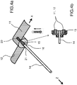
- the figure 4a represents the deployable structure 10 in isometric view and the figure 4b shows a sectional view of the deployable structure.
- the arm 15 is guided in rotation around the shaft 14 at the level of the support 16.
- the arm 15 can form two contacts substantially parallel to the shaft 14 and which can be symmetrical with respect to the shaft 14, the arm being suitable for and controlling the deployment of the measuring tape 11.
- the deployable structure 10 further comprises at least two rollers 20, 21 carried by the arm 15.
- the rollers 20, 21 are in contact with the measuring tape 11.
- the arm 15 has a degree of freedom in rotation around the Z axis.
- the rollers 20, 21 are capable of guiding the measuring tape 11.
- the two rollers 20, 21 make it possible in particular to ensure a correct and synchronized unwinding of the measuring tape 11 around the mandrel 13 and also allow, if the arm 15 is motorized, being able to fold the measuring tape down on the ground or in flight, for example when the flexible structure is mounted on a satellite.
- the rollers 20, 21 make it possible to limit the friction between the arm 15 and the measuring tape 11.
- the invention can be applied to hybrid measuring tapes, consisting of a first motor structure (for example made of carbon fiber) which allows the deployment of the measuring tape, and of a regulating part (thermoelastic or of a material having a transformation temperature significantly lower than that of the main ribbon) which favors or limits deployment as a function of the temperature which is applied to it.
- a first motor structure for example made of carbon fiber
- a regulating part thermoelastic or of a material having a transformation temperature significantly lower than that of the main ribbon
- the rollers 20, 21 can be heating rollers.
- the heating rollers make it possible to locally heat up at two points, at their respective anchorages, the tape measures, thus causing their deployment and also the rotation of the mandrel 13 which can therefore heat the section of tape measure then brought into contact with the rollers 20, 21, as shown diagrammatically on the figure 1b , the arrows indicating the rotation around the Z axis.
- the local heating by the heating rollers makes it possible to obtain a regulated deployment of the structure.
- this configuration is energetically economical since it is not necessary to heat the entire measuring tape and / or the mandrel 13. This characteristic is particularly advantageous for use on satellite.
- the Figures 5a, 5b and 5c represent a deployable structure 50 in the semi-deployed position and in the deployed position as well as a section of the deployable structure 50 comprising two deployable structures 10 according to an unclaimed example.
- the deployable structure 50 can comprise at least one flexible membrane 30.
- the deployable structures 10 respectively comprise two measuring tapes 41 and 42.
- the flexible membrane 30 can be intended to support elements to be deployed such as for example solar cells, metallized cells for the reflection of radio waves, insulating elements to produce a thermal or optical screen, or any other device.
- the flexible membrane 30 is fixed to the tape measures 41, 42.
- the flexible membrane 30 can be stiffened by transverse slats themselves fixed to the tape measures, for example, by gluing, by riveting, stapling or sewing.
- the figure 5c represents a section of the deployable structure 50 comprising two deployable structures 10, and a flexible membrane 30.
- the mandrel 13 is fixed on the shaft 14.
- the arm 15 has a degree of freedom in rotation about the axis Z.
- This example requires a rotating electrical supply system, of the collector or spiral cable type to supply the heating rollers. It is more suitable for a heating mandrel system 13 fixed relative to the shaft 14 and not using a collector. It is also possible to consider another embodiment, as presented on the figure 6 .
- the deployable structure 50 is shown with two measuring tapes. Nevertheless, it is possible to apply the invention to a deployable structure with more than two measuring tapes, for example three or four, in particular to thus obtain better support for the flexible membrane or in the case where the flexible membrane occupies a very large area.
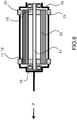
- the figure 6 shows a section of the deployable structure 50 comprising two deployable structures according to a first embodiment.
- the mandrel 13 is fixed on the shaft 14 and both have a degree of freedom in rotation around the axis Z.
- the arm 15 is fixed.
- This embodiment does not require a rotating electrical supply system, of the collector or spiral cable type to supply the heating rollers. In this embodiment, there is no longer any need to compensate for the turns of measuring tape. However, it is necessary to lock the rotation of each measuring tape at the end of deployment of the deployable structure 10.
- the figure 7 represents a means of locking the degree of freedom in rotation about the Z axis of the measuring tape in the deployed position.
- the means of locking the degree of freedom in rotation about the axis Z is a fitting of a portion of measuring tape in the shaft 14.
- the measuring tape 11 can return to its initial position with a slightly concave shape of the face fixed to the mandrel 13 which then fits into the shaft 14. In other words, the measuring tape 11 fits on the shaft 14 in the shape of a key. The rotation along the Z axis of the measuring tape is then locked.
- the figure 8 illustrates in isometric semi-transparent view the locking means of the measuring tape on the mandrel 13 with in detail the curvature of the measuring tape which is embedded at the level of the shaft 14.
- the figure 9 represents another means of stiffening the embedding of the measuring tape. This configuration is similar to that proposed in the figure 8 with an arm 15 carrying the rollers 20, 21 fixed and a shaft 14, a mandrel 13 and measuring tapes 11 and 12 movable in rotation about the axis Z.
- the measuring tape 11 and the mandrel 13 each have two ends.
- the deployable structure 10 comprises two secondary measuring tapes 61, 62 each comprising two ends, a first end 71 of one of the two secondary measuring tapes 61 is fixed at a distance from a first end 81 of the measuring tape 11.
- a second end 72 of the secondary measuring tape 61 is fixed to one end 91 of the mandrel 13.
- a first end 73 of the second secondary measuring tape 62 is fixed at a distance from a second end 82 of the measuring tape 11.
- a second end 74 of the secondary measuring tape 62 is fixed to one end 92 of the mandrel 13.
- Each assembly consisting of a portion of measuring tape, a portion of mandrel and a secondary measuring tape forms in the deployed position a triangulated structure offering excellent rigidity deployed tape measure.
- the arm 15 is shown in dotted lines, but it is obvious that it is linked to the heating rollers 20, 21 to allow good guidance of the measuring tape and the deployment of the measuring tape by local heating as explained above .
- the deployment of the measuring tape can be regulated and controlled.
- Secondary tape measures can be convex section tape measures or flat blades.
- a tape measure in the deployed configuration offers good tensile strength but also compression (within a certain limit). It therefore allows it to be used alone as a "strut” as described above. On the other hand, it offers less good storage capacity than a strip because of this more bulky recess.
- the secondary measuring tapes constitute a triangulation system on the measuring tape 11.
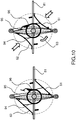
- the figure 10 represents a means 96 for automatic buckling of the secondary tape measures 61, 62.
- the buckling force can be obtained by means of a motor allowing the structure to be rewound.
- the motor is linked to a pulley 93 driving, via cables or tape 94, the measuring tapes 61, 62.
- the pulley 93 via a stop 95, comes into contact with the mandrel 13, the motor drives the mandrel 13 so to rewind the structure.
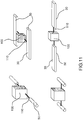
- the figure 11 represents a satellite 100 comprising at least one deployable structure 50 equipped with a flexible membrane 30 and at least 2 deployable structures 10.
- the deployable structure 50 further comprises an articulated mast 110 deployable fixed on a platform of the satellite 100 by the intermediate for example of a rotary drive motor.
- the flexible membrane 30 is fully deployed.
- the satellite 100 includes a second flexible membrane 30.
- the two structures deployable 50 are positioned on either side of the satellite 100.
- the flexible structure 50 can be positioned in a T shape relative to the satellite 100 (configuration shown figure 2 ), that is to say that its main longitudinal direction is perpendicular to the articulated mast 110.
- the flexible structure can also be positioned in the shape of an I (configuration shown figure 1 ), with respect to the satellite 100, that is to say that its main longitudinal direction is in the extension of the articulated mast 110.
- the deployable structure 50 is used only for a single deployment. Nevertheless, new mission needs appear.
- the piloting of the transfer vehicle requires as little inertia as possible, that is to say that the presence of deployable structures of large dimensions is not favorable. It is also necessary to avoid any interference with the satellites that we are trying to dock. Therefore, it is preferable to roll up the deployable structures. When the satellite is attached, the structure can be deployed again.
- the invention presents a simplicity of assembly, with few parts to assemble.
- the course of the measuring tape is well controlled. Indeed, the measuring tape can be guided by the rollers 20, 21, and locally heated in the case where the rollers 20, 21 are heated, thus making it possible to regulate its deployment.
- stacking can be autonomous because it is obtained by the bi-stability of the measuring tape (hybrid or not) with its two stable positions (rolled up and deployed).
- the invention can also be applied with non-hybrid or non-bistable measuring tapes.
- the deployment is regulated by a gearmotor (which retains the torque of the measuring tape), replacing the couple (thermoplastic / heating rollers).
Landscapes
- Engineering & Computer Science (AREA)
- Architecture (AREA)
- Remote Sensing (AREA)
- Aviation & Aerospace Engineering (AREA)
- Civil Engineering (AREA)
- Structural Engineering (AREA)
- Life Sciences & Earth Sciences (AREA)
- Sustainable Development (AREA)
- Details Of Aerials (AREA)
- Aerials With Secondary Devices (AREA)
Claims (10)
- Entfaltbare Struktur (10), Folgendes beinhaltend:• eine Stütze (16),• ein an der Stütze (16) befestigtes Maßband (11, 12), welches geeignet ist, von einer um eine Achse Z eingerollten Konfiguration in eine entfaltete Konfiguration überzugehen, wobei das Maßband zwei Enden (81, 82) besitzt,
dadurch gekennzeichnet, dass sie zudem Folgendes beinhaltet
einen in Bezug auf die Stütze (16) um die Achse Z drehbar beweglichen Arm (15), welcher geeignet ist, einen ersten Kontakt mit dem Maßband (11, 12) zu bilden, um so die Entfaltung des Maßbandes (11, 12) zu steuern, dadurch, dass das Maßband (11, 12) zwischen seinen beiden Enden an einem Befestigungspunkt an der Stütze (16) befestigt ist,
dadurch, dass der Arm (15) geeignet ist, einen zweiten Kontakt mit dem Maßband (11, 12) zu bilden, um so die Entfaltung des Maßbandes (11, 12) zu steuern,
dadurch, dass ein erstes Ende geeignet ist, sich in Bezug auf den Befestigungspunkten entlang einer ersten Achse, welche rechtwinklig zur Achse Z ist, in eine erste Richtung zu entfalten,
dadurch, dass ein zweites Ende geeignet ist, sich entlang einer zweiten Achse, welche rechtwinklig zur Achse Z ist, in eine zweite Richtung zu entfalten, welche sich von der ersten Richtung unterscheidet,
und dadurch, dass die beiden Enden geeignet sind, sich gleichzeitig zu entfalten. - Entfaltbare Struktur (10) nach dem vorhergehenden Anspruch, dadurch gekennzeichnet, dass sie zudem einen Dorn (13) und eine Welle (14) beinhaltet, welche im Wesentlichen parallel zur Achse Z ist, und dadurch, dass der Dorn (13) an der Welle (14) befestigt ist und dadurch, dass das Maßband (11, 12) um den Dorn (13) aufgerollt ist.
- Entfaltbare Struktur (10) nach einem der vorhergehenden Ansprüche, dadurch gekennzeichnet, dass der Arm (15) zwei Rollen (20, 21) trägt, wobei die Rollen in Kontakt mit dem Maßband (11) sind und dadurch gekennzeichnet, dass die Rollen (20, 21) geeignet sind, das Maßband (11) zu führen.
- Entfaltbare Struktur (10) nach Anspruch 3, dadurch gekennzeichnet, dass die Rollen (20, 21) Heizrollen sind, und dadurch, dass die Rollen (20, 21) in der Lage sind, das Maßband (11) lokal zu erwärmen.
- Entfaltbare Struktur (10) nach einem der Ansprüche 3 oder 4, dadurch gekennzeichnet, dass sie zudem ein Verriegelungsmittel des Drehfreiheitsgrades um die Achse Z des Arms (15) beinhaltet.
- Entfaltbare Struktur (10) nach Anspruch 5, dadurch gekennzeichnet, dass das Verriegelungsmittel des Drehfreiheitsgrades um die Achse Z eine Einbettung eines Abschnittes des Maßbandes (11) in der Welle (14) ist.
- Entfaltbare Struktur (10) nach einem der Ansprüche 5 oder 6, wobei der Arm (15) zwei Enden (91, 92) beinhaltet und der Dorn (13) zwei Enden beinhaltet, dadurch gekennzeichnet, dass sie zwei sekundäre Maßbänder (61, 62) beinhaltet, welche jeweils zwei Enden (71, 72, 73, 74) beinhalten, wobei ein erstes Ende (71, 73) eines der beiden sekundären Maßbänder (61, 62) in einem Abstand von einem ersten Ende (81) des Maßbandes (11) befestigt ist und dadurch, dass ein zweites Ende (72, 74) des sekundären Maßbandes (61, 62) an einem Ende (91, 92) des Dorns (13) befestigt ist.
- Entfaltbare Struktur (10) nach Anspruch 7, dadurch gekennzeichnet, dass sie sekundären Maßbänder (61, 62) ebene Blätter sind.
- Entfaltbare Struktur (10) nach einem der vorhergehenden Ansprüche, dadurch gekennzeichnet, dass sie zudem einen entfaltbaren gelenkigen Mast (110) beinhaltet, welcher an einer Plattform eines Satelliten (100) in Vermittlung eines Drehantriebsmotors befestigt ist.
- Satellit (100), dadurch gekennzeichnet, dass er mindestens eine entfaltbare Struktur (10) nach dem vorhergehenden Anspruch beinhaltet.
Applications Claiming Priority (1)
| Application Number | Priority Date | Filing Date | Title |
|---|---|---|---|
| FR1401712A FR3024228B1 (fr) | 2014-07-25 | 2014-07-25 | Structure deployable a metre-ruban |
Publications (2)
| Publication Number | Publication Date |
|---|---|
| EP2977323A1 EP2977323A1 (de) | 2016-01-27 |
| EP2977323B1 true EP2977323B1 (de) | 2020-03-25 |
Family
ID=51688121
Family Applications (1)
| Application Number | Title | Priority Date | Filing Date |
|---|---|---|---|
| EP15177172.2A Active EP2977323B1 (de) | 2014-07-25 | 2015-07-16 | Entfaltbare struktur mit federband |
Country Status (6)
| Country | Link |
|---|---|
| US (1) | US9669949B2 (de) |
| EP (1) | EP2977323B1 (de) |
| JP (1) | JP6669445B2 (de) |
| CA (1) | CA2897024C (de) |
| ES (1) | ES2799423T3 (de) |
| FR (1) | FR3024228B1 (de) |
Families Citing this family (17)
| Publication number | Priority date | Publication date | Assignee | Title |
|---|---|---|---|---|
| FR2998876B1 (fr) * | 2012-12-05 | 2015-07-17 | Thales Sa | Dispositif de deploiement et de reploiement d'une structure flexible, structure deployable flexible et satellite munis d'un tel dispositif |
| US10263316B2 (en) * | 2013-09-06 | 2019-04-16 | MMA Design, LLC | Deployable reflectarray antenna structure |
| US10241293B2 (en) * | 2014-09-26 | 2019-03-26 | Massachusetts Institute Of Technology | Methods and apparatus for deployable sparse-aperture telescopes |
| US9856039B2 (en) * | 2014-10-08 | 2018-01-02 | Analytical Mechanics Associates, Inc. | Extendable solar array for a spacecraft system |
| US10189583B2 (en) * | 2015-05-13 | 2019-01-29 | Analytical Mechanics Associates, Inc. | Deployable sheet material systems and methods |
| FR3048418B1 (fr) * | 2016-03-02 | 2019-04-19 | Thales | Dispositif de deploiement et de pointage |
| EP3468868B1 (de) * | 2016-06-14 | 2021-05-19 | Blomquist, Richard | Raumfahrzeug und steuerungsverfahren |
| KR101872612B1 (ko) * | 2016-11-10 | 2018-06-28 | 한국항공우주연구원 | 우주 쓰레기 제거용 위성 |
| US10326539B2 (en) * | 2017-04-12 | 2019-06-18 | Rohde & Schwarz Gmbh & Co. Kg | Test system and test method |
| FR3070049B1 (fr) * | 2017-08-10 | 2019-09-06 | Airbus Defence And Space Sas | Procede de fabrication dans l'espace de structures de grandes dimensions |
| FR3098651B1 (fr) * | 2019-07-11 | 2022-07-08 | Thales Sa | Dispositif de deploiement tridimensionnel |
| FR3110552A1 (fr) * | 2020-05-20 | 2021-11-26 | Thales | Véhicule en orbite avec membrane enroulable et déployable pour le contrôle d’attitude et d’orbite |
| CN114929075B (zh) * | 2020-07-21 | 2023-08-18 | 黎明科技有限公司 | 电动螺旋抽缩件及利用该电动螺旋抽缩件的系统、设备、装置和方法 |
| CN115367150B (zh) * | 2022-08-03 | 2024-05-17 | 银河航天(北京)网络技术有限公司 | 一种剪叉式太阳翼系统 |
| CN116053767A (zh) * | 2023-02-21 | 2023-05-02 | 南京航空航天大学 | 一种具有缓释功能的卷尺天线 |
| WO2025203256A1 (ja) * | 2024-03-26 | 2025-10-02 | 三菱電機株式会社 | ヒンジ及び展開構造物 |
| CN119683015B (zh) * | 2025-01-23 | 2025-09-02 | 苏州馥昶空间技术有限公司 | 一种展开机构及航天器 |
Family Cites Families (12)
| Publication number | Priority date | Publication date | Assignee | Title |
|---|---|---|---|---|
| FR803986A (fr) | 1935-07-03 | 1936-10-13 | épingle pour fixer les tôles avant rivetage | |
| FR1203300A (fr) | 1958-09-16 | 1960-01-18 | Genre de construction à plates-formes nues étagées pour aménagement de maisons légères individuelles | |
| US3544041A (en) * | 1967-11-07 | 1970-12-01 | Communications Satellite Corp | Deployable flexible solar array |
| US4506446A (en) * | 1983-02-22 | 1985-03-26 | Rodger Mitchell | Tape measure having two tapes |
| GB2216870A (en) * | 1988-04-08 | 1989-10-18 | Peter Joseph Searle | Centre-finding tape measure |
| US6904722B2 (en) * | 2001-02-21 | 2005-06-14 | The United States Of America As Represented By The Secretary Of The Navy | Elongated truss boom structures for space applications |
| US8185783B2 (en) * | 2007-11-22 | 2012-05-22 | Microsoft Corporation | Split user-mode/kernel-mode device driver architecture |
| FR2933771B1 (fr) | 2008-07-11 | 2010-08-13 | Thales Sa | Metre ruban a deploiement thermique et structure deployable comportant ledit metre ruban |
| US8683755B1 (en) * | 2010-01-21 | 2014-04-01 | Deployable Space Systems, Inc. | Directionally controlled elastically deployable roll-out solar array |
| FR2969985B1 (fr) * | 2010-12-30 | 2016-09-09 | Thales Sa | Générateur solaire plan deroulable |
| FR2969984B1 (fr) * | 2010-12-30 | 2013-02-08 | Thales Sa | Générateur solaire deroulable caissonne |
| FR2998876B1 (fr) * | 2012-12-05 | 2015-07-17 | Thales Sa | Dispositif de deploiement et de reploiement d'une structure flexible, structure deployable flexible et satellite munis d'un tel dispositif |
-
2014
- 2014-07-25 FR FR1401712A patent/FR3024228B1/fr not_active Expired - Fee Related
-
2015
- 2015-07-10 CA CA2897024A patent/CA2897024C/en active Active
- 2015-07-16 EP EP15177172.2A patent/EP2977323B1/de active Active
- 2015-07-16 ES ES15177172T patent/ES2799423T3/es active Active
- 2015-07-16 JP JP2015141879A patent/JP6669445B2/ja active Active
- 2015-07-21 US US14/805,317 patent/US9669949B2/en active Active
Non-Patent Citations (1)
| Title |
|---|
| None * |
Also Published As
| Publication number | Publication date |
|---|---|
| US20160023781A1 (en) | 2016-01-28 |
| CA2897024C (en) | 2022-06-21 |
| ES2799423T3 (es) | 2020-12-17 |
| CA2897024A1 (en) | 2016-01-25 |
| FR3024228B1 (fr) | 2018-02-09 |
| US9669949B2 (en) | 2017-06-06 |
| EP2977323A1 (de) | 2016-01-27 |
| JP6669445B2 (ja) | 2020-03-18 |
| FR3024228A1 (fr) | 2016-01-29 |
| JP2016030595A (ja) | 2016-03-07 |
Similar Documents
| Publication | Publication Date | Title |
|---|---|---|
| EP2977322B1 (de) | Verfahren zum versenkbaren einbau eines massbands für eine entfaltbare struktur, und entfaltbare struktur mit massband | |
| EP2977323A1 (de) | Entfaltbare struktur mit federband | |
| EP3023333B1 (de) | Ausfahrbare und einziehbare struktur mit massband | |
| CA2834593C (fr) | Dispositif de deploiement et de reploiement d'une structure flexible, structure deployable flexible et satellite munis d'un tel dispositif | |
| EP2471714B1 (de) | Abrollbarer ebener Solargenerator | |
| WO2009153454A2 (fr) | Structure articulee deployable | |
| EP2471713B1 (de) | Abwickelbarer kastenförmiger Solargenerator | |
| EP3433173B1 (de) | Raumfahrzeug | |
| EP3640146B1 (de) | Entfaltbare vorrichtung mit massbändern | |
| FR2596205A1 (fr) | Ensemble et appareil de deploiement de structures pliees, telles que des antennes | |
| EP3176095A1 (de) | Ausklappbare struktur, die eine gesamtheit von solargeneratoren umfasst, ausklappsystem einer solchen ausklappbaren struktur und satellit, der ein solches system umfasst | |
| FR3015131A1 (fr) | Structure segmentee, en particulier pour reflecteur d'antenne de satellite, pourvue d'au moins un dispositif de deploiement a ruban | |
| EP2520494B1 (de) | Vorrichtung zum Schutz eines optischen Vielfachspiegelinstruments | |
| EP3795480B1 (de) | Ausklappbare vorrichtung | |
| EP0818602A1 (de) | Auf- und Abrollvorrichtung für ein Gewebe | |
| FR2486493A1 (fr) | Perfectionnements apportes aux systemes de repliement et de stabilisation des panneaux solaires | |
| EP4321702B1 (de) | Sonnen- oder wetterschutzanlage | |
| FR3051443A1 (fr) | Engin spatial | |
| FR2466652A1 (fr) | Fleche telescopique | |
| EP0239454A1 (de) | Bewegungsmechanismus für ein Teil und seine Bestimmung für einen entfaltbaren Solarzellengenerator | |
| FR3090024A1 (fr) | Dispositif d’enroulement d’une bâche à barres pour piscine et procédé d’enroulement | |
| WO2025124891A1 (fr) | Dispositif de transmission de données | |
| FR2717207A1 (fr) | Mât porteur du type enroulable en matériau composite et son dispositif de mise en Óoeuvre. | |
| FR3157039A1 (fr) | Dispositif de transmission de données | |
| FR3060536A1 (fr) | Engin spatial |
Legal Events
| Date | Code | Title | Description |
|---|---|---|---|
| PUAI | Public reference made under article 153(3) epc to a published international application that has entered the european phase |
Free format text: ORIGINAL CODE: 0009012 |
|
| AK | Designated contracting states |
Kind code of ref document: A1 Designated state(s): AL AT BE BG CH CY CZ DE DK EE ES FI FR GB GR HR HU IE IS IT LI LT LU LV MC MK MT NL NO PL PT RO RS SE SI SK SM TR |
|
| AX | Request for extension of the european patent |
Extension state: BA ME |
|
| 17P | Request for examination filed |
Effective date: 20160704 |
|
| RBV | Designated contracting states (corrected) |
Designated state(s): AL AT BE BG CH CY CZ DE DK EE ES FI FR GB GR HR HU IE IS IT LI LT LU LV MC MK MT NL NO PL PT RO RS SE SI SK SM TR |
|
| GRAP | Despatch of communication of intention to grant a patent |
Free format text: ORIGINAL CODE: EPIDOSNIGR1 |
|
| STAA | Information on the status of an ep patent application or granted ep patent |
Free format text: STATUS: GRANT OF PATENT IS INTENDED |
|
| INTG | Intention to grant announced |
Effective date: 20191125 |
|
| GRAS | Grant fee paid |
Free format text: ORIGINAL CODE: EPIDOSNIGR3 |
|
| GRAA | (expected) grant |
Free format text: ORIGINAL CODE: 0009210 |
|
| STAA | Information on the status of an ep patent application or granted ep patent |
Free format text: STATUS: THE PATENT HAS BEEN GRANTED |
|
| AK | Designated contracting states |
Kind code of ref document: B1 Designated state(s): AL AT BE BG CH CY CZ DE DK EE ES FI FR GB GR HR HU IE IS IT LI LT LU LV MC MK MT NL NO PL PT RO RS SE SI SK SM TR |
|
| REG | Reference to a national code |
Ref country code: GB Ref legal event code: FG4D Free format text: NOT ENGLISH |
|
| REG | Reference to a national code |
Ref country code: AT Ref legal event code: REF Ref document number: 1248297 Country of ref document: AT Kind code of ref document: T Effective date: 20200415 Ref country code: IE Ref legal event code: FG4D Free format text: LANGUAGE OF EP DOCUMENT: FRENCH |
|
| REG | Reference to a national code |
Ref country code: DE Ref legal event code: R096 Ref document number: 602015049276 Country of ref document: DE |
|
| REG | Reference to a national code |
Ref country code: CH Ref legal event code: NV Representative=s name: SERVOPATENT GMBH, CH |
|
| REG | Reference to a national code |
Ref country code: CH Ref legal event code: PCOW |
|
| REG | Reference to a national code |
Ref country code: NL Ref legal event code: FP |
|
| PG25 | Lapsed in a contracting state [announced via postgrant information from national office to epo] |
Ref country code: RS Free format text: LAPSE BECAUSE OF FAILURE TO SUBMIT A TRANSLATION OF THE DESCRIPTION OR TO PAY THE FEE WITHIN THE PRESCRIBED TIME-LIMIT Effective date: 20200325 Ref country code: FI Free format text: LAPSE BECAUSE OF FAILURE TO SUBMIT A TRANSLATION OF THE DESCRIPTION OR TO PAY THE FEE WITHIN THE PRESCRIBED TIME-LIMIT Effective date: 20200325 Ref country code: NO Free format text: LAPSE BECAUSE OF FAILURE TO SUBMIT A TRANSLATION OF THE DESCRIPTION OR TO PAY THE FEE WITHIN THE PRESCRIBED TIME-LIMIT Effective date: 20200625 |
|
| PG25 | Lapsed in a contracting state [announced via postgrant information from national office to epo] |
Ref country code: BG Free format text: LAPSE BECAUSE OF FAILURE TO SUBMIT A TRANSLATION OF THE DESCRIPTION OR TO PAY THE FEE WITHIN THE PRESCRIBED TIME-LIMIT Effective date: 20200625 Ref country code: GR Free format text: LAPSE BECAUSE OF FAILURE TO SUBMIT A TRANSLATION OF THE DESCRIPTION OR TO PAY THE FEE WITHIN THE PRESCRIBED TIME-LIMIT Effective date: 20200626 Ref country code: HR Free format text: LAPSE BECAUSE OF FAILURE TO SUBMIT A TRANSLATION OF THE DESCRIPTION OR TO PAY THE FEE WITHIN THE PRESCRIBED TIME-LIMIT Effective date: 20200325 Ref country code: LV Free format text: LAPSE BECAUSE OF FAILURE TO SUBMIT A TRANSLATION OF THE DESCRIPTION OR TO PAY THE FEE WITHIN THE PRESCRIBED TIME-LIMIT Effective date: 20200325 Ref country code: SE Free format text: LAPSE BECAUSE OF FAILURE TO SUBMIT A TRANSLATION OF THE DESCRIPTION OR TO PAY THE FEE WITHIN THE PRESCRIBED TIME-LIMIT Effective date: 20200325 |
|
| REG | Reference to a national code |
Ref country code: LT Ref legal event code: MG4D |
|
| PG25 | Lapsed in a contracting state [announced via postgrant information from national office to epo] |
Ref country code: IS Free format text: LAPSE BECAUSE OF FAILURE TO SUBMIT A TRANSLATION OF THE DESCRIPTION OR TO PAY THE FEE WITHIN THE PRESCRIBED TIME-LIMIT Effective date: 20200725 Ref country code: SK Free format text: LAPSE BECAUSE OF FAILURE TO SUBMIT A TRANSLATION OF THE DESCRIPTION OR TO PAY THE FEE WITHIN THE PRESCRIBED TIME-LIMIT Effective date: 20200325 Ref country code: PT Free format text: LAPSE BECAUSE OF FAILURE TO SUBMIT A TRANSLATION OF THE DESCRIPTION OR TO PAY THE FEE WITHIN THE PRESCRIBED TIME-LIMIT Effective date: 20200818 Ref country code: RO Free format text: LAPSE BECAUSE OF FAILURE TO SUBMIT A TRANSLATION OF THE DESCRIPTION OR TO PAY THE FEE WITHIN THE PRESCRIBED TIME-LIMIT Effective date: 20200325 Ref country code: CZ Free format text: LAPSE BECAUSE OF FAILURE TO SUBMIT A TRANSLATION OF THE DESCRIPTION OR TO PAY THE FEE WITHIN THE PRESCRIBED TIME-LIMIT Effective date: 20200325 Ref country code: LT Free format text: LAPSE BECAUSE OF FAILURE TO SUBMIT A TRANSLATION OF THE DESCRIPTION OR TO PAY THE FEE WITHIN THE PRESCRIBED TIME-LIMIT Effective date: 20200325 Ref country code: EE Free format text: LAPSE BECAUSE OF FAILURE TO SUBMIT A TRANSLATION OF THE DESCRIPTION OR TO PAY THE FEE WITHIN THE PRESCRIBED TIME-LIMIT Effective date: 20200325 Ref country code: SM Free format text: LAPSE BECAUSE OF FAILURE TO SUBMIT A TRANSLATION OF THE DESCRIPTION OR TO PAY THE FEE WITHIN THE PRESCRIBED TIME-LIMIT Effective date: 20200325 |
|
| REG | Reference to a national code |
Ref country code: AT Ref legal event code: MK05 Ref document number: 1248297 Country of ref document: AT Kind code of ref document: T Effective date: 20200325 |
|
| REG | Reference to a national code |
Ref country code: ES Ref legal event code: FG2A Ref document number: 2799423 Country of ref document: ES Kind code of ref document: T3 Effective date: 20201217 |
|
| REG | Reference to a national code |
Ref country code: DE Ref legal event code: R097 Ref document number: 602015049276 Country of ref document: DE |
|
| PG25 | Lapsed in a contracting state [announced via postgrant information from national office to epo] |
Ref country code: DK Free format text: LAPSE BECAUSE OF FAILURE TO SUBMIT A TRANSLATION OF THE DESCRIPTION OR TO PAY THE FEE WITHIN THE PRESCRIBED TIME-LIMIT Effective date: 20200325 Ref country code: AT Free format text: LAPSE BECAUSE OF FAILURE TO SUBMIT A TRANSLATION OF THE DESCRIPTION OR TO PAY THE FEE WITHIN THE PRESCRIBED TIME-LIMIT Effective date: 20200325 |
|
| PLBE | No opposition filed within time limit |
Free format text: ORIGINAL CODE: 0009261 |
|
| STAA | Information on the status of an ep patent application or granted ep patent |
Free format text: STATUS: NO OPPOSITION FILED WITHIN TIME LIMIT |
|
| PG25 | Lapsed in a contracting state [announced via postgrant information from national office to epo] |
Ref country code: PL Free format text: LAPSE BECAUSE OF FAILURE TO SUBMIT A TRANSLATION OF THE DESCRIPTION OR TO PAY THE FEE WITHIN THE PRESCRIBED TIME-LIMIT Effective date: 20200325 Ref country code: MC Free format text: LAPSE BECAUSE OF FAILURE TO SUBMIT A TRANSLATION OF THE DESCRIPTION OR TO PAY THE FEE WITHIN THE PRESCRIBED TIME-LIMIT Effective date: 20200325 |
|
| 26N | No opposition filed |
Effective date: 20210112 |
|
| REG | Reference to a national code |
Ref country code: BE Ref legal event code: MM Effective date: 20200731 |
|
| PG25 | Lapsed in a contracting state [announced via postgrant information from national office to epo] |
Ref country code: LU Free format text: LAPSE BECAUSE OF NON-PAYMENT OF DUE FEES Effective date: 20200716 |
|
| PG25 | Lapsed in a contracting state [announced via postgrant information from national office to epo] |
Ref country code: SI Free format text: LAPSE BECAUSE OF FAILURE TO SUBMIT A TRANSLATION OF THE DESCRIPTION OR TO PAY THE FEE WITHIN THE PRESCRIBED TIME-LIMIT Effective date: 20200325 Ref country code: BE Free format text: LAPSE BECAUSE OF NON-PAYMENT OF DUE FEES Effective date: 20200731 |
|
| PG25 | Lapsed in a contracting state [announced via postgrant information from national office to epo] |
Ref country code: IE Free format text: LAPSE BECAUSE OF NON-PAYMENT OF DUE FEES Effective date: 20200716 |
|
| PG25 | Lapsed in a contracting state [announced via postgrant information from national office to epo] |
Ref country code: TR Free format text: LAPSE BECAUSE OF FAILURE TO SUBMIT A TRANSLATION OF THE DESCRIPTION OR TO PAY THE FEE WITHIN THE PRESCRIBED TIME-LIMIT Effective date: 20200325 Ref country code: MT Free format text: LAPSE BECAUSE OF FAILURE TO SUBMIT A TRANSLATION OF THE DESCRIPTION OR TO PAY THE FEE WITHIN THE PRESCRIBED TIME-LIMIT Effective date: 20200325 Ref country code: CY Free format text: LAPSE BECAUSE OF FAILURE TO SUBMIT A TRANSLATION OF THE DESCRIPTION OR TO PAY THE FEE WITHIN THE PRESCRIBED TIME-LIMIT Effective date: 20200325 |
|
| PG25 | Lapsed in a contracting state [announced via postgrant information from national office to epo] |
Ref country code: MK Free format text: LAPSE BECAUSE OF FAILURE TO SUBMIT A TRANSLATION OF THE DESCRIPTION OR TO PAY THE FEE WITHIN THE PRESCRIBED TIME-LIMIT Effective date: 20200325 Ref country code: AL Free format text: LAPSE BECAUSE OF FAILURE TO SUBMIT A TRANSLATION OF THE DESCRIPTION OR TO PAY THE FEE WITHIN THE PRESCRIBED TIME-LIMIT Effective date: 20200325 |
|
| PGFP | Annual fee paid to national office [announced via postgrant information from national office to epo] |
Ref country code: GB Payment date: 20250619 Year of fee payment: 11 |
|
| PGFP | Annual fee paid to national office [announced via postgrant information from national office to epo] |
Ref country code: NL Payment date: 20250627 Year of fee payment: 11 |
|
| PGFP | Annual fee paid to national office [announced via postgrant information from national office to epo] |
Ref country code: FR Payment date: 20250623 Year of fee payment: 11 |
|
| PGFP | Annual fee paid to national office [announced via postgrant information from national office to epo] |
Ref country code: ES Payment date: 20250804 Year of fee payment: 11 |
|
| PGFP | Annual fee paid to national office [announced via postgrant information from national office to epo] |
Ref country code: DE Payment date: 20250618 Year of fee payment: 11 |
|
| PGFP | Annual fee paid to national office [announced via postgrant information from national office to epo] |
Ref country code: IT Payment date: 20250626 Year of fee payment: 11 |
|
| PGFP | Annual fee paid to national office [announced via postgrant information from national office to epo] |
Ref country code: CH Payment date: 20250801 Year of fee payment: 11 |