EP2977331B1 - Manchon d'enfichage destine a recevoir un outil - Google Patents
Manchon d'enfichage destine a recevoir un outil Download PDFInfo
- Publication number
- EP2977331B1 EP2977331B1 EP15002053.5A EP15002053A EP2977331B1 EP 2977331 B1 EP2977331 B1 EP 2977331B1 EP 15002053 A EP15002053 A EP 15002053A EP 2977331 B1 EP2977331 B1 EP 2977331B1
- Authority
- EP
- European Patent Office
- Prior art keywords
- socket
- groove
- sleeve portion
- lobe
- peripheral wall
- Prior art date
- Legal status (The legal status is an assumption and is not a legal conclusion. Google has not performed a legal analysis and makes no representation as to the accuracy of the status listed.)
- Active
Links
Images

Classifications
-
- B—PERFORMING OPERATIONS; TRANSPORTING
- B25—HAND TOOLS; PORTABLE POWER-DRIVEN TOOLS; MANIPULATORS
- B25H—WORKSHOP EQUIPMENT, e.g. FOR MARKING-OUT WORK; STORAGE MEANS FOR WORKSHOPS
- B25H3/00—Storage means or arrangements for workshops facilitating access to, or handling of, work tools or instruments
- B25H3/006—Storage means specially adapted for one specific hand apparatus, e.g. an electric drill
-
- B—PERFORMING OPERATIONS; TRANSPORTING
- B65—CONVEYING; PACKING; STORING; HANDLING THIN OR FILAMENTARY MATERIAL
- B65D—CONTAINERS FOR STORAGE OR TRANSPORT OF ARTICLES OR MATERIALS, e.g. BAGS, BARRELS, BOTTLES, BOXES, CANS, CARTONS, CRATES, DRUMS, JARS, TANKS, HOPPERS, FORWARDING CONTAINERS; ACCESSORIES, CLOSURES, OR FITTINGS THEREFOR; PACKAGING ELEMENTS; PACKAGES
- B65D21/00—Nestable, stackable or joinable containers; Containers of variable capacity
- B65D21/08—Containers of variable capacity
- B65D21/086—Collapsible or telescopic containers
Definitions
- the invention relates to a receptacle for receiving a tool, such as a tool. a milling tool for a milling machine or a drill for a drilling machine.
- the plug-in sleeve consists of an inner sleeve part and a push-on thereto, adjacent outer sleeve part, wherein both sleeve parts have a peripheral wall and a bottom wall.
- the two sleeve parts are pulled apart in the axial direction and thereby separated from each other. Since the two sleeve parts are releasably fixed in the initial position by the engagement of locking knobs, the two sleeve parts are often pulled apart with considerable force quickly, the tool falling from the socket to the ground and can be damaged.
- the WO 94/24008 A1 discloses a receptacle with an inner sleeve part and an outer sleeve part which can be pushed thereon, the respectively selected length of which can be detachably fixed by engagement of latching nubs in webs, wherein one of the sleeve parts has at least one longitudinal groove. This groove, which runs next to the webs, is formed continuously up to the edge of the sleeve part.
- the two sleeve parts can be separated from each other at each length adjustment of the socket by the outer sleeve parts is rotated on the inner sleeve member so that the locking knobs are forced over a running next to the row of webs elevation rib, whereupon the knobs enter the groove , In this position, the outer sleeve part can be removed in the axial direction of the inner sleeve part.
- the sleeve parts can be released by mutual rotation at each length setting of the respective locking connection and deducted from each other.
- the present invention has for its object to develop a receptacle of the type under consideration so that the likelihood of such damage is significantly reduced.
- the invention provides that one of the sleeve parts has at least one groove extending in the longitudinal direction of the plug-in sleeve, into which groove a protruding cam of the other sleeve part engages.
- the end walls at the ends of the groove thereby form stops for the at least one cam, so that the cam can not escape from the groove in the axial direction.
- the invention provides that only at the end remote from the bottom end of the at least one groove means are formed, which allow a lateral exit of the cam from the groove, so that after a rotational movement of the outer sleeve member relative to the inner sleeve member of the cam of the Groove emerges and now the two sleeve parts are separable from each other in the longitudinal direction.
- the socket consists of a material that is elastically deformable so that the two sleeve parts this rotational movement and the subsequent pulling apart of the sleeve parts allows.
- a suitable material is for example polypropylene.
- the at least one groove or trough-shaped recess is formed on the outside or in the peripheral wall of the inner sleeve part, while the at least one cam or projection is formed on the inside of the peripheral wall of the outer sleeve part.
- the at least one cam is also located on the end region of the outer sleeve part facing away from the bottom.
- the arrangement may also be reversed, in that the at least one cam protrudes outwardly from the peripheral wall of the inner sleeve part, while the at least one groove is formed on the inside or in the peripheral wall of the outer sleeve part.
- At least two grooves and two cams are formed. These two grooves and two cams are provided on opposite portions of the peripheral walls.
- grooves are provided in all four wall sections, while the other sleeve part contains two cams.
- This design has the advantage that the two sleeve parts can be reassembled in a particularly simple manner, since the cams in each circumferential position of the two sleeve parts when pushing together automatically get into two grooves or snap.
- the means which allow the exit of the at least one cam from its groove consist of at least one oblique side wall portion of the groove and / or at least one oblique side wall of the cam.
- the peripheral wall of the inner sleeve part includes a guide for separating the two sleeve parts, which is only exposed when the outer sleeve part is advanced to the axial stop.
- these instructions for separating the two sleeve parts may include the words "turn and pull" or consist of two arrows indicating the rotation and subsequent axial displacement. This instruction is only visible when the two sleeve parts are actually rotatable against each other.
- the two sleeve parts have a recessed bottom with an outer web.
- This bridge preferably runs diagonally across the ground. If - as is preferred - the sleeve parts are produced in the extrusion blow molding process, this diagonal mold separation with a suitably sized Quetschsteg causes an effective impact protection for packaged tools, since the Quetschbalken can absorb a shock under the retracted soil.
- the sleeve parts preferably have a square cross-sectional shape, the corners of which can be bevelled.
- the plug-in sleeve can also have a different cross-sectional shape, for example round, oval or generally rectangular.
- the socket can be adapted to the length of the respective tool.
- the advantage of a square or rectangular cross-sectional shape of the receptacle is that the receptacle does not roll on a pad and may possibly fall from a table and that such receptacles are well stackable.
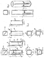
- a groove extending in the longitudinal direction or groove-shaped recess 4 is formed, which ends at a distance from the bottom wall 5 and the free end 6 of the sleeve part 1.
- the front ends 7 of the grooves 4 extend approximately at right angles to the lateral wall sections 3.
- At least one longitudinal wall 8 of the grooves 4 also extends perpendicular to the peripheral wall.
- the illustrated embodiment is produced by an extrusion blow molding process with a diagonal mold separation 14 in which a pinch web 16 is formed under the slightly inwardly curved bottom wall 15 ( FIG. 7 ).
- the relatively long Quetschsteg 16 allows together with the retracted shape of the bottom 15 has a spring action that protects a tool received in the receptacle in a hard impact from damage.
- the outer sleeve part 11 also has a square cylindrical shape with slightly larger dimensions, so that the outer sleeve part 11 can be pushed onto the inner sleeve part 1 so that the parts practically abut each other.
- the outer sleeve member 11 includes on two opposite side walls in each case inwardly projecting cam 9 whose position coincides with two grooves 4 in the circumferential direction.
- the cams 9 have a right angle to the peripheral wall extending end wall 17 and on the opposite side a slope 18.
- the end wall 17 limits the initial pulling apart of the sleeve parts 1 and 11 by abutting the front end wall 7 of the respective groove 4.
- the outer sleeve member When the tool located in the receptacle is to be removed, the outer sleeve member is displaced axially to the stop, which in the Figures 3 . 6 and 8 is shown. In this position, the inscription "turn and pull" on an outer wall 3 of the inner sleeve part 1 is visible. Now, when the outer sleeve member 11 is rotated relative to the inner sleeve member 1 in the direction of the arrow 19 in Figure 8, the knobs slide 9 on the inclined portions 10 at the end portion of the grooves 4 away. Now, the outer sleeve member 11 can be deducted in the direction of arrow 20 in Figure 8 of the inner sleeve part 1.
Landscapes
- Engineering & Computer Science (AREA)
- Mechanical Engineering (AREA)
- Packaging Of Annular Or Rod-Shaped Articles, Wearing Apparel, Cassettes, Or The Like (AREA)
- Mutual Connection Of Rods And Tubes (AREA)
Claims (10)
- Manchon d'enfichage pour recevoir un outil, comprenant une partie de manchon intérieure (1) et une partie de manchon extérieure (11) pouvant être enfilée sur celle-ci, dans lequel les deux parties de manchon (1, 11) ont une paroi périphérique et une paroi de fond (5), dans lequel en outre une longueur respectivement sélectionnée du manchon d'enfichage peut être fixée de manière amovible par la prise de boutons d'encliquetage (12) et de nervures (13) et dans lequel une des parties de manchon (1, 11) présente au moins une rainure (4) longitudinale, caractérisé en ce
qu'une came (9) faisant saillie de l'une des parties de manchon (1, 11) vient en prise avec l'au moins une rainure (4) longitudinale de l'autre partie de manchon (1, 11),
que les parois frontales (7) de l'au moins une rainure (4) forment des butées pour l'au moins une came (9), et que des moyens (10) sont réalisés, seulement au niveau de la zone d'extrémité, opposée au fond (15), de l'au moins une rainure, pour faire sortir de manière latérale la came (9) de la rainure (4) de telle manière que les deux parties de manchon peuvent être séparées l'une de l'autre dans la direction longitudinale après un déplacement par rotation de la partie de manchon extérieure (11) par rapport à la partie de manchon intérieure (1). - Manchon d'enfichage selon la revendication 1, caractérisé en ce
que l'au moins une rainure (4) est réalisée côté extérieur au niveau de la paroi périphérique de la partie de manchon intérieure, et en ce que l'au moins une came (9) est réalisée côté intérieur au niveau de la paroi périphérique de la partie de manchon (11) extérieure. - Manchon d'enfichage selon les revendications 1 ou 2, caractérisé en ce
qu'au moins deux, de préférence quatre rainures (4) et deux cames (9) sont réalisées. - Manchon d'enfichage selon les revendications 1 à 3, caractérisé en ce
que les moyens (10) pour faire sortir la came présentent au moins une section de paroi latérale oblique de la rainure (4) et/ou au moins une paroi latérale oblique de la came. - Manchon d'enfichage selon la revendication 4, caractérisé en ce
que les autres sections de paroi latérale (8) de la rainure et les parois latérales (7) de celle-ci s'étendent à angle droit par rapport à la paroi périphérique. - Manchon d'enfichage selon les revendications 1 à 5, caractérisé en ce
que la paroi périphérique de la partie de manchon intérieure (1) contient une instruction pour séparer les deux parties de manchon (1, 11), qui est alors dégagée quand l'au moins une came (9) repose au niveau de la paroi frontale (7), faisant office de butée, de l'au moins une rainure (4). - Manchon d'enfichage selon les revendications 1 à 6, caractérisé en ce
que les deux parties de manchon (1, 11) présentent un fond (15) rentré pourvu d'une nervure (16). - Manchon d'enfichage selon la revendication 7 caractérisé en ce
que les nervures (16) s'étendent de manière diagonale. - Manchon d'enfichage selon les revendications 1 à 8, caractérisé en ce
que les parties de manchon (1, 11) ont une forme de section de transversale carrée, pourvue de coins (2) biseautés. - Manchon d'enfichage selon la revendication 9, caractérisé en ce
que sont réalisés, au niveau des coins (2) biseautés de la partie de manchon intérieure (1), des boutons d'encliquetage (12) et, au niveau de la partie de manchon extérieure (11) de petites nervures (13), qui sont en prise les uns avec les autres et qui fixent de manière amovible la longueur sélectionnée du manchon d'enfichage.
Applications Claiming Priority (1)
| Application Number | Priority Date | Filing Date | Title |
|---|---|---|---|
| DE202014005960.8U DE202014005960U1 (de) | 2014-07-24 | 2014-07-24 | Steckhülse zur Aufnahme eines Werkzeugs |
Publications (2)
| Publication Number | Publication Date |
|---|---|
| EP2977331A1 EP2977331A1 (fr) | 2016-01-27 |
| EP2977331B1 true EP2977331B1 (fr) | 2016-09-14 |
Family
ID=51618762
Family Applications (1)
| Application Number | Title | Priority Date | Filing Date |
|---|---|---|---|
| EP15002053.5A Active EP2977331B1 (fr) | 2014-07-24 | 2015-07-09 | Manchon d'enfichage destine a recevoir un outil |
Country Status (2)
| Country | Link |
|---|---|
| EP (1) | EP2977331B1 (fr) |
| DE (2) | DE202014005960U1 (fr) |
Families Citing this family (1)
| Publication number | Priority date | Publication date | Assignee | Title |
|---|---|---|---|---|
| DE102015217208A1 (de) | 2015-09-09 | 2017-03-09 | Bayerische Motoren Werke Aktiengesellschaft | Stapelvorrichtung zum Stapeln von Lack- und Montagestopfen |
Citations (11)
| Publication number | Priority date | Publication date | Assignee | Title |
|---|---|---|---|---|
| FR2428577A3 (fr) | 1978-05-19 | 1980-01-11 | Rosler Peter | Receptacle d'emballage pour objets allonges |
| US4596340A (en) | 1985-06-12 | 1986-06-24 | Luther Mark B | Adjustable storage container |
| GB2203729A (en) | 1987-03-19 | 1988-10-26 | Metal Box Plc | Closure systems for containers |
| US4991729A (en) | 1989-04-18 | 1991-02-12 | Hunter Robert M | Elder-accessible child-resistant packaging |
| WO1994024008A1 (fr) | 1991-10-18 | 1994-10-27 | Ab Cerbo-Hertila | Dispositif telescopique |
| GB2287015A (en) | 1994-03-03 | 1995-09-06 | Peter Roesler | Variable length container |
| US5746530A (en) | 1994-03-01 | 1998-05-05 | Oota; Etsuji | Medium container and its spare medium |
| EP1486428A1 (fr) | 2003-06-11 | 2004-12-15 | KH LLoreda, S.A. | Filetage de vis pour bouteilles avec un col de bouteille à une structure asymétrique |
| WO2013171749A1 (fr) | 2012-05-17 | 2013-11-21 | Plasel Plastic Ltd. | Ensemble de fixation et récipient le comprenant |
| DE102012011599A1 (de) | 2012-06-13 | 2013-12-19 | Rose Plastic Ag | Polygonartige Schiebeverpackung mit Dreh-Schub-Bewegung zum Öffnen und Verschließen |
| EP2848548A1 (fr) | 2013-09-16 | 2015-03-18 | rose plastic AG | Emballage coulissant polygonal avec un mouvement de tirer-pousser pour l'ouverture et la fermeture |
-
2014
- 2014-07-24 DE DE202014005960.8U patent/DE202014005960U1/de not_active Expired - Lifetime
- 2014-08-22 DE DE102014012628.5A patent/DE102014012628B3/de not_active Expired - Fee Related
-
2015
- 2015-07-09 EP EP15002053.5A patent/EP2977331B1/fr active Active
Patent Citations (12)
| Publication number | Priority date | Publication date | Assignee | Title |
|---|---|---|---|---|
| FR2428577A3 (fr) | 1978-05-19 | 1980-01-11 | Rosler Peter | Receptacle d'emballage pour objets allonges |
| US4596340A (en) | 1985-06-12 | 1986-06-24 | Luther Mark B | Adjustable storage container |
| GB2203729A (en) | 1987-03-19 | 1988-10-26 | Metal Box Plc | Closure systems for containers |
| US4991729A (en) | 1989-04-18 | 1991-02-12 | Hunter Robert M | Elder-accessible child-resistant packaging |
| WO1994024008A1 (fr) | 1991-10-18 | 1994-10-27 | Ab Cerbo-Hertila | Dispositif telescopique |
| US5746530A (en) | 1994-03-01 | 1998-05-05 | Oota; Etsuji | Medium container and its spare medium |
| GB2287015A (en) | 1994-03-03 | 1995-09-06 | Peter Roesler | Variable length container |
| DE4406932A1 (de) | 1994-03-03 | 1995-09-14 | Peter Roesler | Verpackungsbehälter mit veränderbarer Länge |
| EP1486428A1 (fr) | 2003-06-11 | 2004-12-15 | KH LLoreda, S.A. | Filetage de vis pour bouteilles avec un col de bouteille à une structure asymétrique |
| WO2013171749A1 (fr) | 2012-05-17 | 2013-11-21 | Plasel Plastic Ltd. | Ensemble de fixation et récipient le comprenant |
| DE102012011599A1 (de) | 2012-06-13 | 2013-12-19 | Rose Plastic Ag | Polygonartige Schiebeverpackung mit Dreh-Schub-Bewegung zum Öffnen und Verschließen |
| EP2848548A1 (fr) | 2013-09-16 | 2015-03-18 | rose plastic AG | Emballage coulissant polygonal avec un mouvement de tirer-pousser pour l'ouverture et la fermeture |
Also Published As
| Publication number | Publication date |
|---|---|
| EP2977331A1 (fr) | 2016-01-27 |
| DE202014005960U1 (de) | 2014-09-10 |
| DE102014012628B3 (de) | 2015-09-10 |
Similar Documents
| Publication | Publication Date | Title |
|---|---|---|
| DE69301369T2 (de) | Betonanker | |
| DE2804709A1 (de) | Kunststoffbefestiger | |
| DE8912367U1 (de) | Vorrichtung zum Sichern des Deckels einer Dose, insbesondere Farbdose | |
| DE102007039368A1 (de) | Einfallkern für ein Kunststoffspritzwerkzeug | |
| DE4414381A1 (de) | Vorrichtung zum Verbinden einer Verkleidung mit einer Unterverkleidung | |
| AT10630U1 (de) | Abziehwerkzeug zum abziehen von radschrauben-hutkappen | |
| DE202013008357U1 (de) | Behälterdose und Halteeinrichtung | |
| CH451601A (de) | Befestigungsmittel | |
| EP2848548B1 (fr) | Emballage coulissant polygonal avec un mouvement de tirer-pousser pour l'ouverture et la fermeture | |
| DE102015103222A1 (de) | Zerkleinerungsvorrichtung zum Schneiden von Lebensmitteln, insbesondere zum Schneiden von Knoblauch | |
| EP2156060B1 (fr) | Dispositif de fixation permettant d'assembler un profilé et un contre-profilé de façon libérable | |
| DE102014012628B3 (de) | Steckhülse zur Aufnahme eines Werkzeugs | |
| EP3106684A1 (fr) | Double ecrou | |
| DE2222270A1 (de) | Drehbare befestigungsvorrichtung fuer zwei miteinander zu verbindende elemente | |
| EP3067160B1 (fr) | Dispositif de stockage pour outils | |
| DE102015221765B3 (de) | Zylinderanordnung mit einem Boden und Vorrichtung zur Herstellung einer Formschlussverbindung zwischen dem Boden und einem Zylinder | |
| EP2821042A1 (fr) | Applicateur de tampon et méthode d'assemblage | |
| DE2459506A1 (de) | Klauenanordnung fuer ein expansionswerkzeug | |
| DE102008056202A1 (de) | Gleitlager | |
| DE3424075C2 (de) | Steckverbinder | |
| DE1400222A1 (de) | Selbstschneidender Schraubengewinde-Koerper | |
| DE1750179A1 (de) | Gewinde-Verbindung,insbesondere Sicherungsschraube | |
| DE2058668B2 (de) | Befestigungselement | |
| DE102006027258B4 (de) | Seitenlasche für Kettenglieder einer Energieführungskette | |
| DE102012110294B4 (de) | Griffummantelung, Werkzeugstab mit dieser Griffummantelung und jeweiliges Zusammenbauverfahren dafür |
Legal Events
| Date | Code | Title | Description |
|---|---|---|---|
| PUAI | Public reference made under article 153(3) epc to a published international application that has entered the european phase |
Free format text: ORIGINAL CODE: 0009012 |
|
| AK | Designated contracting states |
Kind code of ref document: A1 Designated state(s): AL AT BE BG CH CY CZ DE DK EE ES FI FR GB GR HR HU IE IS IT LI LT LU LV MC MK MT NL NO PL PT RO RS SE SI SK SM TR |
|
| AX | Request for extension of the european patent |
Extension state: BA ME |
|
| 17P | Request for examination filed |
Effective date: 20160219 |
|
| RBV | Designated contracting states (corrected) |
Designated state(s): AL AT BE BG CH CY CZ DE DK EE ES FI FR GB GR HR HU IE IS IT LI LT LU LV MC MK MT NL NO PL PT RO RS SE SI SK SM TR |
|
| RIC1 | Information provided on ipc code assigned before grant |
Ipc: B65D 21/08 20060101AFI20160420BHEP Ipc: B25H 3/00 20060101ALI20160420BHEP |
|
| GRAP | Despatch of communication of intention to grant a patent |
Free format text: ORIGINAL CODE: EPIDOSNIGR1 |
|
| INTG | Intention to grant announced |
Effective date: 20160610 |
|
| GRAS | Grant fee paid |
Free format text: ORIGINAL CODE: EPIDOSNIGR3 |
|
| GRAA | (expected) grant |
Free format text: ORIGINAL CODE: 0009210 |
|
| AK | Designated contracting states |
Kind code of ref document: B1 Designated state(s): AL AT BE BG CH CY CZ DE DK EE ES FI FR GB GR HR HU IE IS IT LI LT LU LV MC MK MT NL NO PL PT RO RS SE SI SK SM TR |
|
| REG | Reference to a national code |
Ref country code: GB Ref legal event code: FG4D Free format text: NOT ENGLISH |
|
| REG | Reference to a national code |
Ref country code: CH Ref legal event code: EP |
|
| REG | Reference to a national code |
Ref country code: IE Ref legal event code: FG4D Free format text: LANGUAGE OF EP DOCUMENT: GERMAN |
|
| REG | Reference to a national code |
Ref country code: AT Ref legal event code: REF Ref document number: 828689 Country of ref document: AT Kind code of ref document: T Effective date: 20161015 |
|
| REG | Reference to a national code |
Ref country code: DE Ref legal event code: R096 Ref document number: 502015000145 Country of ref document: DE |
|
| REG | Reference to a national code |
Ref country code: CH Ref legal event code: NV Representative=s name: KIRKER AND CIE S.A., CH |
|
| REG | Reference to a national code |
Ref country code: LT Ref legal event code: MG4D |
|
| REG | Reference to a national code |
Ref country code: NL Ref legal event code: MP Effective date: 20160914 |
|
| PG25 | Lapsed in a contracting state [announced via postgrant information from national office to epo] |
Ref country code: RS Free format text: LAPSE BECAUSE OF FAILURE TO SUBMIT A TRANSLATION OF THE DESCRIPTION OR TO PAY THE FEE WITHIN THE PRESCRIBED TIME-LIMIT Effective date: 20160914 Ref country code: LT Free format text: LAPSE BECAUSE OF FAILURE TO SUBMIT A TRANSLATION OF THE DESCRIPTION OR TO PAY THE FEE WITHIN THE PRESCRIBED TIME-LIMIT Effective date: 20160914 Ref country code: HR Free format text: LAPSE BECAUSE OF FAILURE TO SUBMIT A TRANSLATION OF THE DESCRIPTION OR TO PAY THE FEE WITHIN THE PRESCRIBED TIME-LIMIT Effective date: 20160914 Ref country code: NO Free format text: LAPSE BECAUSE OF FAILURE TO SUBMIT A TRANSLATION OF THE DESCRIPTION OR TO PAY THE FEE WITHIN THE PRESCRIBED TIME-LIMIT Effective date: 20161214 Ref country code: FI Free format text: LAPSE BECAUSE OF FAILURE TO SUBMIT A TRANSLATION OF THE DESCRIPTION OR TO PAY THE FEE WITHIN THE PRESCRIBED TIME-LIMIT Effective date: 20160914 |
|
| PG25 | Lapsed in a contracting state [announced via postgrant information from national office to epo] |
Ref country code: NL Free format text: LAPSE BECAUSE OF FAILURE TO SUBMIT A TRANSLATION OF THE DESCRIPTION OR TO PAY THE FEE WITHIN THE PRESCRIBED TIME-LIMIT Effective date: 20160914 Ref country code: SE Free format text: LAPSE BECAUSE OF FAILURE TO SUBMIT A TRANSLATION OF THE DESCRIPTION OR TO PAY THE FEE WITHIN THE PRESCRIBED TIME-LIMIT Effective date: 20160914 Ref country code: GR Free format text: LAPSE BECAUSE OF FAILURE TO SUBMIT A TRANSLATION OF THE DESCRIPTION OR TO PAY THE FEE WITHIN THE PRESCRIBED TIME-LIMIT Effective date: 20161215 Ref country code: LV Free format text: LAPSE BECAUSE OF FAILURE TO SUBMIT A TRANSLATION OF THE DESCRIPTION OR TO PAY THE FEE WITHIN THE PRESCRIBED TIME-LIMIT Effective date: 20160914 |
|
| PG25 | Lapsed in a contracting state [announced via postgrant information from national office to epo] |
Ref country code: RO Free format text: LAPSE BECAUSE OF FAILURE TO SUBMIT A TRANSLATION OF THE DESCRIPTION OR TO PAY THE FEE WITHIN THE PRESCRIBED TIME-LIMIT Effective date: 20160914 Ref country code: EE Free format text: LAPSE BECAUSE OF FAILURE TO SUBMIT A TRANSLATION OF THE DESCRIPTION OR TO PAY THE FEE WITHIN THE PRESCRIBED TIME-LIMIT Effective date: 20160914 |
|
| PG25 | Lapsed in a contracting state [announced via postgrant information from national office to epo] |
Ref country code: SM Free format text: LAPSE BECAUSE OF FAILURE TO SUBMIT A TRANSLATION OF THE DESCRIPTION OR TO PAY THE FEE WITHIN THE PRESCRIBED TIME-LIMIT Effective date: 20160914 Ref country code: CZ Free format text: LAPSE BECAUSE OF FAILURE TO SUBMIT A TRANSLATION OF THE DESCRIPTION OR TO PAY THE FEE WITHIN THE PRESCRIBED TIME-LIMIT Effective date: 20160914 Ref country code: PT Free format text: LAPSE BECAUSE OF FAILURE TO SUBMIT A TRANSLATION OF THE DESCRIPTION OR TO PAY THE FEE WITHIN THE PRESCRIBED TIME-LIMIT Effective date: 20170116 Ref country code: BG Free format text: LAPSE BECAUSE OF FAILURE TO SUBMIT A TRANSLATION OF THE DESCRIPTION OR TO PAY THE FEE WITHIN THE PRESCRIBED TIME-LIMIT Effective date: 20161214 Ref country code: PL Free format text: LAPSE BECAUSE OF FAILURE TO SUBMIT A TRANSLATION OF THE DESCRIPTION OR TO PAY THE FEE WITHIN THE PRESCRIBED TIME-LIMIT Effective date: 20160914 Ref country code: SK Free format text: LAPSE BECAUSE OF FAILURE TO SUBMIT A TRANSLATION OF THE DESCRIPTION OR TO PAY THE FEE WITHIN THE PRESCRIBED TIME-LIMIT Effective date: 20160914 Ref country code: IS Free format text: LAPSE BECAUSE OF FAILURE TO SUBMIT A TRANSLATION OF THE DESCRIPTION OR TO PAY THE FEE WITHIN THE PRESCRIBED TIME-LIMIT Effective date: 20170114 Ref country code: ES Free format text: LAPSE BECAUSE OF FAILURE TO SUBMIT A TRANSLATION OF THE DESCRIPTION OR TO PAY THE FEE WITHIN THE PRESCRIBED TIME-LIMIT Effective date: 20160914 |
|
| REG | Reference to a national code |
Ref country code: DE Ref legal event code: R026 Ref document number: 502015000145 Country of ref document: DE |
|
| REG | Reference to a national code |
Ref country code: FR Ref legal event code: PLFP Year of fee payment: 3 |
|
| PLBI | Opposition filed |
Free format text: ORIGINAL CODE: 0009260 |
|
| PLAX | Notice of opposition and request to file observation + time limit sent |
Free format text: ORIGINAL CODE: EPIDOSNOBS2 |
|
| PG25 | Lapsed in a contracting state [announced via postgrant information from national office to epo] |
Ref country code: DK Free format text: LAPSE BECAUSE OF FAILURE TO SUBMIT A TRANSLATION OF THE DESCRIPTION OR TO PAY THE FEE WITHIN THE PRESCRIBED TIME-LIMIT Effective date: 20160914 |
|
| 26 | Opposition filed |
Opponent name: ROESLER IP GMBH Effective date: 20170613 |
|
| PLBB | Reply of patent proprietor to notice(s) of opposition received |
Free format text: ORIGINAL CODE: EPIDOSNOBS3 |
|
| PG25 | Lapsed in a contracting state [announced via postgrant information from national office to epo] |
Ref country code: SI Free format text: LAPSE BECAUSE OF FAILURE TO SUBMIT A TRANSLATION OF THE DESCRIPTION OR TO PAY THE FEE WITHIN THE PRESCRIBED TIME-LIMIT Effective date: 20160914 |
|
| REG | Reference to a national code |
Ref country code: IE Ref legal event code: MM4A |
|
| PG25 | Lapsed in a contracting state [announced via postgrant information from national office to epo] |
Ref country code: IE Free format text: LAPSE BECAUSE OF NON-PAYMENT OF DUE FEES Effective date: 20170709 |
|
| REG | Reference to a national code |
Ref country code: BE Ref legal event code: MM Effective date: 20170731 |
|
| PG25 | Lapsed in a contracting state [announced via postgrant information from national office to epo] |
Ref country code: LU Free format text: LAPSE BECAUSE OF NON-PAYMENT OF DUE FEES Effective date: 20170709 |
|
| REG | Reference to a national code |
Ref country code: FR Ref legal event code: PLFP Year of fee payment: 4 |
|
| PG25 | Lapsed in a contracting state [announced via postgrant information from national office to epo] |
Ref country code: BE Free format text: LAPSE BECAUSE OF NON-PAYMENT OF DUE FEES Effective date: 20170731 |
|
| PG25 | Lapsed in a contracting state [announced via postgrant information from national office to epo] |
Ref country code: MT Free format text: LAPSE BECAUSE OF FAILURE TO SUBMIT A TRANSLATION OF THE DESCRIPTION OR TO PAY THE FEE WITHIN THE PRESCRIBED TIME-LIMIT Effective date: 20160914 |
|
| PLCK | Communication despatched that opposition was rejected |
Free format text: ORIGINAL CODE: EPIDOSNREJ1 |
|
| STAA | Information on the status of an ep patent application or granted ep patent |
Free format text: STATUS: THE PATENT HAS BEEN GRANTED |
|
| REG | Reference to a national code |
Ref country code: DE Ref legal event code: R100 Ref document number: 502015000145 Country of ref document: DE |
|
| PG25 | Lapsed in a contracting state [announced via postgrant information from national office to epo] |
Ref country code: AL Free format text: LAPSE BECAUSE OF FAILURE TO SUBMIT A TRANSLATION OF THE DESCRIPTION OR TO PAY THE FEE WITHIN THE PRESCRIBED TIME-LIMIT Effective date: 20160914 |
|
| PLBN | Opposition rejected |
Free format text: ORIGINAL CODE: 0009273 |
|
| STAA | Information on the status of an ep patent application or granted ep patent |
Free format text: STATUS: OPPOSITION REJECTED |
|
| 27O | Opposition rejected |
Effective date: 20181014 |
|
| PG25 | Lapsed in a contracting state [announced via postgrant information from national office to epo] |
Ref country code: MC Free format text: LAPSE BECAUSE OF FAILURE TO SUBMIT A TRANSLATION OF THE DESCRIPTION OR TO PAY THE FEE WITHIN THE PRESCRIBED TIME-LIMIT Effective date: 20160914 Ref country code: HU Free format text: LAPSE BECAUSE OF FAILURE TO SUBMIT A TRANSLATION OF THE DESCRIPTION OR TO PAY THE FEE WITHIN THE PRESCRIBED TIME-LIMIT; INVALID AB INITIO Effective date: 20150709 |
|
| PG25 | Lapsed in a contracting state [announced via postgrant information from national office to epo] |
Ref country code: CY Free format text: LAPSE BECAUSE OF FAILURE TO SUBMIT A TRANSLATION OF THE DESCRIPTION OR TO PAY THE FEE WITHIN THE PRESCRIBED TIME-LIMIT Effective date: 20160914 |
|
| PG25 | Lapsed in a contracting state [announced via postgrant information from national office to epo] |
Ref country code: MK Free format text: LAPSE BECAUSE OF FAILURE TO SUBMIT A TRANSLATION OF THE DESCRIPTION OR TO PAY THE FEE WITHIN THE PRESCRIBED TIME-LIMIT Effective date: 20160914 |
|
| PG25 | Lapsed in a contracting state [announced via postgrant information from national office to epo] |
Ref country code: TR Free format text: LAPSE BECAUSE OF FAILURE TO SUBMIT A TRANSLATION OF THE DESCRIPTION OR TO PAY THE FEE WITHIN THE PRESCRIBED TIME-LIMIT Effective date: 20160914 |
|
| REG | Reference to a national code |
Ref country code: AT Ref legal event code: MM01 Ref document number: 828689 Country of ref document: AT Kind code of ref document: T Effective date: 20200709 |
|
| PG25 | Lapsed in a contracting state [announced via postgrant information from national office to epo] |
Ref country code: AT Free format text: LAPSE BECAUSE OF NON-PAYMENT OF DUE FEES Effective date: 20200709 |
|
| P01 | Opt-out of the competence of the unified patent court (upc) registered |
Effective date: 20230512 |
|
| PGFP | Annual fee paid to national office [announced via postgrant information from national office to epo] |
Ref country code: FR Payment date: 20230607 Year of fee payment: 9 |
|
| PGFP | Annual fee paid to national office [announced via postgrant information from national office to epo] |
Ref country code: IT Payment date: 20230731 Year of fee payment: 9 Ref country code: CH Payment date: 20230801 Year of fee payment: 9 |
|
| REG | Reference to a national code |
Ref country code: CH Ref legal event code: PL |
|
| PG25 | Lapsed in a contracting state [announced via postgrant information from national office to epo] |
Ref country code: CH Free format text: LAPSE BECAUSE OF NON-PAYMENT OF DUE FEES Effective date: 20240731 |
|
| PG25 | Lapsed in a contracting state [announced via postgrant information from national office to epo] |
Ref country code: FR Free format text: LAPSE BECAUSE OF NON-PAYMENT OF DUE FEES Effective date: 20240731 |
|
| PGFP | Annual fee paid to national office [announced via postgrant information from national office to epo] |
Ref country code: GB Payment date: 20250624 Year of fee payment: 11 |
|
| PG25 | Lapsed in a contracting state [announced via postgrant information from national office to epo] |
Ref country code: IT Free format text: LAPSE BECAUSE OF NON-PAYMENT OF DUE FEES Effective date: 20240709 |
|
| PGFP | Annual fee paid to national office [announced via postgrant information from national office to epo] |
Ref country code: DE Payment date: 20250916 Year of fee payment: 11 |