EP2977532B1 - Système de poignée extérieure pour une porte de véhicule - Google Patents
Système de poignée extérieure pour une porte de véhicule Download PDFInfo
- Publication number
- EP2977532B1 EP2977532B1 EP14382284.9A EP14382284A EP2977532B1 EP 2977532 B1 EP2977532 B1 EP 2977532B1 EP 14382284 A EP14382284 A EP 14382284A EP 2977532 B1 EP2977532 B1 EP 2977532B1
- Authority
- EP
- European Patent Office
- Prior art keywords
- positive
- base part
- handle system
- locking element
- external handle
- Prior art date
- Legal status (The legal status is an assumption and is not a legal conclusion. Google has not performed a legal analysis and makes no representation as to the accuracy of the status listed.)
- Not-in-force
Links
Images


Classifications
-
- E—FIXED CONSTRUCTIONS
- E05—LOCKS; KEYS; WINDOW OR DOOR FITTINGS; SAFES
- E05B—LOCKS; ACCESSORIES THEREFOR; HANDCUFFS
- E05B85/00—Details of vehicle locks not provided for in groups E05B77/00 - E05B83/00
- E05B85/10—Handles
- E05B85/14—Handles pivoted about an axis parallel to the wing
- E05B85/16—Handles pivoted about an axis parallel to the wing a longitudinal grip part being pivoted at one end about an axis perpendicular to the longitudinal axis of the grip part
-
- E—FIXED CONSTRUCTIONS
- E05—LOCKS; KEYS; WINDOW OR DOOR FITTINGS; SAFES
- E05B—LOCKS; ACCESSORIES THEREFOR; HANDCUFFS
- E05B79/00—Mounting or connecting vehicle locks or parts thereof
- E05B79/02—Mounting of vehicle locks or parts thereof
- E05B79/06—Mounting of handles, e.g. to the wing or to the lock
Definitions
- the invention relates to an exterior handle system for a vehicle door according to the combination of features of claim 1 of the invention.
- T2 is an outside handle system for a vehicle door, in particular side door, known, which outer handle system on the one hand has an elongated handle main body which extends in the vehicle longitudinal direction (X-direction).
- the handle main body is pivotally mounted at one end to a first base member made of metal.
- the first base member is mounted by means of a screw on an outer surface of the vehicle door.
- the outer handle system has a second base member made of metal, which connects to the pivot bearing opposite end of the handle main body and is also mounted by means of a screw on the outer surface of the vehicle door.
- EP1026351 A1 Document is also known: A handle has placed carrier in door interior. External handle has fastening heel transversely inward through the hole in the outer panel and engaged to assist. Handle for fastening heel part, locks, to move on support and is controlled between unlocking and locking positions by control mechanism and maneuvered through the opening in the door edge panel.
- the handle has an outdoor unit with a mounting shaft and is transversely engaged in a handle carrier.
- a shaft locking unit is slidably mounted in the carrier between locking and unlocking positions.
- a control screw bolted a threaded portion in the carrier and a front cooperating free end with the portion of the locking unit surface.
- An elastically deformable unit is inserted between the end and the section. A tight is received in a complementary housing of the shaft in the locking position.
- the illustrated actuator is used for doors and flaps, especially on a motor vehicle, use. It contains a support that can be fastened to the door, either a lock cylinder or a lock Verposedungspatrappe having tower, which is subsequently inserted into an opening of the carrier and the turret end is accessible from the outside of the door, and a carrier disposed on the locking element which is movable between a lock in the carrier locking position and a release unlocking the tower position.
- the locking element has at least one arm pivotable to the tower, which engages behind a shoulder on the tower in the locked position.
- a vehicle door handle assembly comprising: a door handle having opposed first and second ends, the first end including a handle leg connectable to an angle lever; a door handle end cap; a slide lock cassette supporting the angle lever; and a frame supporting the door handle and the door handle end cap.
- the frame is fixable to a vehicle door and defines an opening which receives the slide lock cassette therein. The opening is sized to allow sliding movement of the slide lock cassette therein.
- the slide lock cassette is slidable relative to the frame between a first position in which the handle leg is not connected to the bell crank and the door handle end cap is not fixed relative to the frame, and a second position in which the handle leg is connected to the bell crank and the Door handle end cap is caught by the slide lock cassette before leaving the frame.
- the object of the invention is to provide an alternative with respect to the state of the art outer handle system for a vehicle door, which is expandable with simple and cost manufacturability and assembly in its function, for example, can be performed alternatively with or without lock cylinder of a door lock.
- an outer handle system for a vehicle door with an elongated handle main body, which in turn is pivotally mounted at one end to a fixed to the vehicle door base member by means of a pivot bearing, and with a pivot bearing side of the handle main body and attached to the base cap, which a receiving opening formed in the base part for an attachment or fitting closes, wherein the cover is fastened by mediating a content on the base part Klammerelements by an adjustable positive locking element on the base part, wherein the positive locking element is formed in the closing direction spring loaded, so that the positive locking element pulled against the spring force or pressed and then the cap is released.
- the outer handle system with an attachment or built-in part, for example, a lock cylinder of a door opening and - closing mechanism, which lock cylinder occupies the said receiving opening
- a simple and cost-effective installation of the cap allows, if such an attachment or fitting is not desired.
- the invention is not limited to a built-in or attachment in the form of a door lock cylinder, but covers any arranged in said receiving opening attachment or attachment, for example, a proximity sensor, which is covered by said cap / is.
- the form-locking element is designed to be spring-loaded in the closing direction, whereby an assembly of the cap is allowed without any auxiliary tool.
- the cap is one or two parts formed by a cap support member and a cover member, wherein in assembly the cap support member of the cap on the opposite side of the handle main body of its side wall by the intermediary of the clamping element by the adjustable Positive locking element is attached to the base part.
- Ihara is in training of the invention to the form-locking element associated with a cap formed form-fitting receptacle, in which the positive-locking element automatically penetrates during assembly and causes the desired fit.
- the positive-locking element is formed by an axially adjustable slide element according to a particularly simple design of the invention.
- the positive locking element in the form of the slider element is formed integrally with the clamping element and axially adjustable due to an elastic design of at least one portion of the clamping element carrying the form-locking element.
- the positive-locking element in the form of the slide element can also be designed as a separate component and guided in an axially adjustable manner in a guide bore of the clamping element.
- the clamp element is preferably frame-shaped and, with the receiving opening in the base part at least partially enclosing, preferably held on the base part by positive locking, in particular latching.
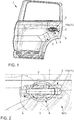
- Fig. 1 first shows a vehicle door 1, in this case a rear left side door of a passenger car, with an outside handle system 2.
- the purposegriffsystem 2 an elongated handle main body 3, which in turn by means of one in the Fig. 4 and 5 pivot bearing 4 shown pivotally mounted on a base part 5 fixed to the vehicle door 1.
- the handle main body 3 is vehicle or door outside in the area of a vehicle-inwardly curved portion or a handle 6 with recess 7 of a door outer part 8, in particular a the outer skin of the vehicle with determining door outer panel arranged, whereas the base part 5 inside door on the door outer part. 8 , in particular door outer panel of the vehicle door 1 is attached.
- the handle main body 3 serves to actuate a door opening and closing mechanism (not shown in the drawing) and is preferably made of a metal and / or plastic.
- the handle main body 3 is designed to be spring-loaded in the pivoting direction by means of a helical torsion spring 9.
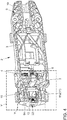
- the base part 5 is formed largely plate-shaped with a plurality of stiffening webs 10 and also formed of metal or plastic. It acts essentially as a support member for the handle main body 3 and any other attachment or mounting parts, which will be discussed further below.
- Swivel bearing side ie, according to the Fig. 1 to 3 right side of the handle main body 3, adjoins the handle main body 3 attached to the base part 5 cap 11 made of, for example, plastic.
- the cap 11 closes a formed in the base part 5 Receiving opening 12 (see. 4 to 6 ) for any provided attached or not illustrated drawing or built-in part.
- the vehicle door / s can also be opened manually by means of a key.
- actuated by means of a key door lock cylinder is considered unnecessary especially for the rear vehicle doors 1 of a passenger car.
- the receiving opening 12 of said attached or built-in part such as a lock cylinder occupied or not. If according to this embodiment, for the said rear vehicle door 1, such an attachment or built-in part is not provided, the receiving opening 12 is closed or covered by means of the cover 11.
- the cap 11 is formed by a cap carrier part 11a and an externally visible lid part 11b.
- Cap carrier part 11a and cover part 11b may be integrally or alternatively formed in two parts, in the latter case, a positive connection between the cap carrier part 11a and the lid part 11b is favored by latching (not shown in the drawing).
- the cap 11 is formed in two parts, which is allowed to inexpensively adjust the visible cover part 11b in terms of color and / or shape to different designs.
- the cap carrier part 11a has on the side opposite the handle main body 3 side of its side wall as a form-fitting receptacle 11c (see. Fig. 6 and 7 ) for an adjustable positive locking element 14 acting opening. Through the intermediary of a retaining element 15 held on the base part 5, the covering cap 11 is fastened to the base part 5 by the adjustable positive-locking element 14 (cf., in particular, FIG. 4 to 6 ).
- the clamp member 15 is formed according to this embodiment frame-shaped and by means of latching elements 16 of the base part 5, which correspond with counter-latching elements 17 of the clamping element 15 on the base part 5 positively fixed.
- the receiving opening 12 in the base part 5 is partially enclosed by the clamping element 15.
- the clamp member 15 also has a limiting web 18 ( Fig. 4-6 . 8th ).
- the form-locking element 14 is formed by an axially adjustable respectively axially in the form of an opening formed form-fitting receptacle 11c of the cap 11 insertable slide element.
- the slide-like form-fitting element 14 is designed to spring-loaded in the closing direction.
- the slide-like interlocking element 14 is integrally formed with the clamp member 15 and axially adjustable due to an elastic design of the form-locking element 14 supporting portion 15a of the present frame-shaped clamp member 15.
- the spring force is applied by means of a spring element 19 in the form of a helical compression spring.
- the spring element 19 respectively the helical compression spring is supported at one end on said side wall 15a and at the other end on an end wall 5a of the base part 5.
- this / s is guided both in a hollow-cylindrical guide element 13 of the base part 5 and on a guide pin 20 of the positive-locking element 14.
- the guide of the helical compression spring can also be limited to the hollow-cylindrical guide element 13 or the guide pin 20 or said guide means can be dispensed with entirely if the helical compression spring has sufficient inherent rigidity against lateral deflection.
- the invention is not limited to said helical compression spring, but covers any suitable spring element 19, for example also a leaf spring or a leaf spring stack, which is accordingly covered by the invention.
- a spring element 19 respectively a helical compression spring, which is formed or connected in one piece with the base part 5 or the clamp element 15.
- the spring element 19 and the helical compression spring for example, by plastic coating with the base part 5 or the clip member 15 are connected from each plastic or even material of uniform design formed in a cast with the base part 5 or the clip member 15.
- the positive-locking element 14 is formed in the form of the slider element as a separate component and guided in a guide bore of the clamping element 15 axially adjustable and spring loaded.
- the receiving opening 12 is not occupied by an attachment or installation part, such as a lock cylinder of a door opening and closing mechanism and should be closed or covered by the above-described cap 11
- such cap 11 is orthogonal or largely orthogonal with the free end of the cap carrier part 11b pressed against the reaching into the receiving opening 12 free end of the spring-loaded and located in the closed position slide-like form-fitting element 14.
- the positive-locking element 14 gives way against the spring force.
- cap 11 respectively the flap support member 11a inserted so far into the receiving opening 12 that positive-locking element 14 and form-fitting receptacle 11c are arranged coaxially to each other, snaps the slide-like interlocking element 14 axially into the opening formed in the cap support member 11a form-fitting receptacle 11c, whereby the cap 11 on Base part 5 is fixed.
- a release of the composite can be achieved, for example, by means of a non-illustrated tool by a in the Fig. 4 and 5 shown disassembly opening 22 in the end wall 5a of the base member 5 through the positive connection element 14 against the spring force of the spring element 19, in the present case in the form of the helical compression spring, pulled or pressed from the positive terminal receptacle 11c and then the cap 11 is released.
- said tool engages on the side wall 15a of the clamping element 15 or on an in Fig. 8 shown dismantling element 23 of the slide-like positive locking element 14.
Landscapes
- Lock And Its Accessories (AREA)
Claims (9)
- Système de poignée externe (2) pour une porte de véhicule (1), ayant un corps principal de poignée longiligne (3), qui est, d'une part, monté de façon pivotante sur une partie de base (5) fixée à la porte de véhicule (1) au moyen d'un palier pivotant (4) et ayant un cache (11) adjacent au corps principal de la poignée (3) sur le côté du palier de pivot et fixé à la partie de base (5), qui scelle une ouverture de réception (12) formée dans la partie de base (5) pour une partie de liaison ou de montage, dans lequel le cache (11) est fixé à la partie de base (5) par un élément de verrouillage positif réglable (14) avec la mise en place d'un élément de fermeture (15) supporté sur la partie de base (5), caractérisé en ce que l'élément de verrouillage positif (14) est conçu de façon montée sur ressort dans le sens de fermeture de sorte que l'élément de verrouillage positif est tiré ou poussé contre la force du ressort et le cache est alors libéré.
- Système de poignée externe (2) selon la revendication 1, caractérisé en ce que le cache (11) est formé en une ou deux pièces par une partie porteuse de cache (11a) et une partie de cache (11b), dans lequel, lorsqu'elles sont assemblées, la partie porteuse de cache (11a) du cache (11) sur le côté de sa paroi latérale en regard du corps principal de la poignée (3) est fixée sur la partie de base (5) par l'élément de verrouillage positif réglable (14) avec la mise en place de l'élément de serrage (15).
- Système de poignée externe (2) selon l'une des revendications 1 à 2, caractérisé en ce qu'une portion de réception de verrouillage positif (11c) formée sur le cache (11) est assignée à l'élément de verrouillage positif (14).
- Système de poignée externe (2) selon l'une quelconque des revendications 1 à 3, caractérisé en ce que l'élément de verrouillage positif est formé par un élément coulissant réglable axialement.
- Système de poignée externe (2) selon la revendication 4, caractérisé en ce que l'élément de verrouillage positif (14) sous la forme de l'élément coulissant est intégralement formé avec l'élément de serrage (15) et est axialement réglable à la suite d'une conception élastique d'au moins une section (15a) de l'élément de serrage (15) portant l'élément de verrouillage positif (14).
- Système de poignée externe (2) selon la revendication 4, caractérisé en ce que l'élément de verrouillage positif (14) sous la forme de l'élément coulissant est formé comme un composant distinct et est guidé de façon réglable axialement dans un orifice de guidage de l'élément de serrage (15).
- Système de poignée externe (2) selon l'une quelconque des revendications 1 à 6, caractérisé en ce que l'élément de serrage (15) est formé sous la forme d'un châssis et l'ouverture de réception (12) dans la partie de base (5) est supportée au moins partiellement refermé sur la partie de base (5).
- Système de poignée externe (2) selon l'une des revendications 1 à 7, caractérisé en ce que l'élément de serrage (15) est supporté sur la partie de base (5) par un assemblage à verrouillage positif.
- Système de poignée externe (2) selon la revendication 8, caractérisé en ce que l'élément de serrage (15) est supporté sur la partie de base (5) par mécanisme à cliquet.
Priority Applications (1)
| Application Number | Priority Date | Filing Date | Title |
|---|---|---|---|
| EP14382284.9A EP2977532B1 (fr) | 2014-07-22 | 2014-07-22 | Système de poignée extérieure pour une porte de véhicule |
Applications Claiming Priority (1)
| Application Number | Priority Date | Filing Date | Title |
|---|---|---|---|
| EP14382284.9A EP2977532B1 (fr) | 2014-07-22 | 2014-07-22 | Système de poignée extérieure pour une porte de véhicule |
Publications (2)
| Publication Number | Publication Date |
|---|---|
| EP2977532A1 EP2977532A1 (fr) | 2016-01-27 |
| EP2977532B1 true EP2977532B1 (fr) | 2018-05-09 |
Family
ID=51228404
Family Applications (1)
| Application Number | Title | Priority Date | Filing Date |
|---|---|---|---|
| EP14382284.9A Not-in-force EP2977532B1 (fr) | 2014-07-22 | 2014-07-22 | Système de poignée extérieure pour une porte de véhicule |
Country Status (1)
| Country | Link |
|---|---|
| EP (1) | EP2977532B1 (fr) |
Families Citing this family (2)
| Publication number | Priority date | Publication date | Assignee | Title |
|---|---|---|---|---|
| US10196842B2 (en) | 2014-06-20 | 2019-02-05 | Huf North America Automotive Parts Manufacturing Corp. | Retention mechanism for insertion member in vehicular door handle assembly |
| EP3667002B1 (fr) * | 2018-12-12 | 2021-05-12 | U-Shin Italia S.p.A. | Dispositif d assemblage d'une poignée d'ouvrant et méthode d'assemblage d'une telle poignée |
Family Cites Families (5)
| Publication number | Priority date | Publication date | Assignee | Title |
|---|---|---|---|---|
| FR2789428B1 (fr) * | 1999-02-05 | 2001-04-13 | Valeo Securite Habitacle | Poignee d'ouvrant de vehicule automobile comportant des moyens perfectionnes de blocage d'un element externe |
| JP3614789B2 (ja) | 2001-03-28 | 2005-01-26 | 株式会社ホンダロック | 車両のアウトハンドル装置 |
| FR2851282B1 (fr) * | 2003-02-18 | 2005-04-08 | Valeo Securite Habitacle | Poignee de vehicule automobile comportant des moyens de blocage d'un element externe |
| DE102004007083B3 (de) * | 2004-02-13 | 2005-09-01 | Huf Hülsbeck & Fürst Gmbh & Co. Kg | Betätigungsvorrichtung für Türen oder Klappen |
| WO2013109306A2 (fr) * | 2011-06-20 | 2013-07-25 | Adac Plastics, Inc. | Ensemble poignée de porte, sous-ensemble et leur procédé d'installation |
-
2014
- 2014-07-22 EP EP14382284.9A patent/EP2977532B1/fr not_active Not-in-force
Non-Patent Citations (1)
| Title |
|---|
| None * |
Also Published As
| Publication number | Publication date |
|---|---|
| EP2977532A1 (fr) | 2016-01-27 |
Similar Documents
| Publication | Publication Date | Title |
|---|---|---|
| EP3245365A1 (fr) | Portière pour véhicule à moteur | |
| EP2491210A1 (fr) | Dispositif poignée doté d'un support de cuvette | |
| EP2845974A2 (fr) | Dispositif de clapet d'obturation pour un dispositif de poignée d'une porte de véhicule automobile | |
| DE102007027845A1 (de) | Vorrichtung zum Betätigen eines Verschlusses eines beweglichen Teils | |
| EP2977532B1 (fr) | Système de poignée extérieure pour une porte de véhicule | |
| EP2167767B1 (fr) | Dispositif d'actionnement d'une serrure d'une pièce mobile | |
| DE10218838C1 (de) | Flächengebilde mit einer Durchgriffsöffnung | |
| DE19924028A1 (de) | Kraftfahrzeugtür | |
| DE102007025359A1 (de) | Betätigungsvorrichtung für ein Türschloss, insbesondere einer Schiebe- oder Schiebeschwenktür | |
| WO2014060154A1 (fr) | Habillage intérieur pour une porte de véhicule, porte de véhicule pourvue d'un tel habillage intérieur ainsi que véhicule | |
| DE102006028570B4 (de) | Schließbügelanordnung für einen Kraftwagen | |
| DE102010007216B4 (de) | Klappenscharnier für Kraftfahrzeug | |
| DE102006032700B3 (de) | Anbindungsvorrichtung für eine Halteeinrichtung eines Deckels eines öffnungsfähigen Fahrzeugdaches | |
| DE102008039442B4 (de) | Kfz-Fronthaubenschloss | |
| EP3394369B1 (fr) | Dispositif permettant d'empêcher mécaniquement une ouverture automatique d'une porte de véhicule, et véhicule muni dudit dispositif | |
| DE102004061141B4 (de) | Türzuziehgriff | |
| DE10032499A1 (de) | An einem Modulträger einer Fahrzeugtür vormontierbare Vorrichtung mit einem Lagerbügel zur Befestigung eines Tür-Außengriffes | |
| DE102007052771A1 (de) | Vorrichtung zur Verbindung von wenigstens zwei Seilzügen miteinander | |
| EP4077843B1 (fr) | Dispositif de guidage pour guider au moins un élément de mobilier mobile | |
| DE102019104161A1 (de) | Fenster für ein Fahrzeug oder einen Container mit einem Verriegelungsmechanismus | |
| EP1525362B1 (fr) | Système comprenant une gâche fixe et un dispositif à fermeture assistée | |
| DE4328494C2 (de) | Schloß für ein Kraftfahrzeug | |
| DE102018204141B4 (de) | System, aufweisend ein Karosserieelement und ein Demontagewerkzeug | |
| DE4446904C1 (de) | Kraftfahrzeug-Türgriff | |
| DE102013003672A1 (de) | Fahrzeug mit einem Haubenelement |
Legal Events
| Date | Code | Title | Description |
|---|---|---|---|
| PUAI | Public reference made under article 153(3) epc to a published international application that has entered the european phase |
Free format text: ORIGINAL CODE: 0009012 |
|
| AK | Designated contracting states |
Kind code of ref document: A1 Designated state(s): AL AT BE BG CH CY CZ DE DK EE ES FI FR GB GR HR HU IE IS IT LI LT LU LV MC MK MT NL NO PL PT RO RS SE SI SK SM TR |
|
| AX | Request for extension of the european patent |
Extension state: BA ME |
|
| 17P | Request for examination filed |
Effective date: 20160725 |
|
| GRAP | Despatch of communication of intention to grant a patent |
Free format text: ORIGINAL CODE: EPIDOSNIGR1 |
|
| INTG | Intention to grant announced |
Effective date: 20180118 |
|
| GRAS | Grant fee paid |
Free format text: ORIGINAL CODE: EPIDOSNIGR3 |
|
| GRAA | (expected) grant |
Free format text: ORIGINAL CODE: 0009210 |
|
| AK | Designated contracting states |
Kind code of ref document: B1 Designated state(s): AL AT BE BG CH CY CZ DE DK EE ES FI FR GB GR HR HU IE IS IT LI LT LU LV MC MK MT NL NO PL PT RO RS SE SI SK SM TR |
|
| REG | Reference to a national code |
Ref country code: GB Ref legal event code: FG4D Free format text: NOT ENGLISH |
|
| REG | Reference to a national code |
Ref country code: CH Ref legal event code: EP Ref country code: AT Ref legal event code: REF Ref document number: 997703 Country of ref document: AT Kind code of ref document: T Effective date: 20180515 |
|
| REG | Reference to a national code |
Ref country code: DE Ref legal event code: R096 Ref document number: 502014008205 Country of ref document: DE Ref country code: IE Ref legal event code: FG4D Free format text: LANGUAGE OF EP DOCUMENT: GERMAN |
|
| REG | Reference to a national code |
Ref country code: FR Ref legal event code: PLFP Year of fee payment: 5 |
|
| REG | Reference to a national code |
Ref country code: NL Ref legal event code: MP Effective date: 20180509 |
|
| REG | Reference to a national code |
Ref country code: LT Ref legal event code: MG4D |
|
| PG25 | Lapsed in a contracting state [announced via postgrant information from national office to epo] |
Ref country code: BG Free format text: LAPSE BECAUSE OF FAILURE TO SUBMIT A TRANSLATION OF THE DESCRIPTION OR TO PAY THE FEE WITHIN THE PRESCRIBED TIME-LIMIT Effective date: 20180809 Ref country code: ES Free format text: LAPSE BECAUSE OF FAILURE TO SUBMIT A TRANSLATION OF THE DESCRIPTION OR TO PAY THE FEE WITHIN THE PRESCRIBED TIME-LIMIT Effective date: 20180509 Ref country code: LT Free format text: LAPSE BECAUSE OF FAILURE TO SUBMIT A TRANSLATION OF THE DESCRIPTION OR TO PAY THE FEE WITHIN THE PRESCRIBED TIME-LIMIT Effective date: 20180509 Ref country code: SE Free format text: LAPSE BECAUSE OF FAILURE TO SUBMIT A TRANSLATION OF THE DESCRIPTION OR TO PAY THE FEE WITHIN THE PRESCRIBED TIME-LIMIT Effective date: 20180509 Ref country code: NO Free format text: LAPSE BECAUSE OF FAILURE TO SUBMIT A TRANSLATION OF THE DESCRIPTION OR TO PAY THE FEE WITHIN THE PRESCRIBED TIME-LIMIT Effective date: 20180809 Ref country code: FI Free format text: LAPSE BECAUSE OF FAILURE TO SUBMIT A TRANSLATION OF THE DESCRIPTION OR TO PAY THE FEE WITHIN THE PRESCRIBED TIME-LIMIT Effective date: 20180509 |
|
| PG25 | Lapsed in a contracting state [announced via postgrant information from national office to epo] |
Ref country code: RS Free format text: LAPSE BECAUSE OF FAILURE TO SUBMIT A TRANSLATION OF THE DESCRIPTION OR TO PAY THE FEE WITHIN THE PRESCRIBED TIME-LIMIT Effective date: 20180509 Ref country code: HR Free format text: LAPSE BECAUSE OF FAILURE TO SUBMIT A TRANSLATION OF THE DESCRIPTION OR TO PAY THE FEE WITHIN THE PRESCRIBED TIME-LIMIT Effective date: 20180509 Ref country code: LV Free format text: LAPSE BECAUSE OF FAILURE TO SUBMIT A TRANSLATION OF THE DESCRIPTION OR TO PAY THE FEE WITHIN THE PRESCRIBED TIME-LIMIT Effective date: 20180509 Ref country code: GR Free format text: LAPSE BECAUSE OF FAILURE TO SUBMIT A TRANSLATION OF THE DESCRIPTION OR TO PAY THE FEE WITHIN THE PRESCRIBED TIME-LIMIT Effective date: 20180810 Ref country code: NL Free format text: LAPSE BECAUSE OF FAILURE TO SUBMIT A TRANSLATION OF THE DESCRIPTION OR TO PAY THE FEE WITHIN THE PRESCRIBED TIME-LIMIT Effective date: 20180509 |
|
| PG25 | Lapsed in a contracting state [announced via postgrant information from national office to epo] |
Ref country code: PL Free format text: LAPSE BECAUSE OF FAILURE TO SUBMIT A TRANSLATION OF THE DESCRIPTION OR TO PAY THE FEE WITHIN THE PRESCRIBED TIME-LIMIT Effective date: 20180509 Ref country code: SK Free format text: LAPSE BECAUSE OF FAILURE TO SUBMIT A TRANSLATION OF THE DESCRIPTION OR TO PAY THE FEE WITHIN THE PRESCRIBED TIME-LIMIT Effective date: 20180509 Ref country code: CZ Free format text: LAPSE BECAUSE OF FAILURE TO SUBMIT A TRANSLATION OF THE DESCRIPTION OR TO PAY THE FEE WITHIN THE PRESCRIBED TIME-LIMIT Effective date: 20180509 Ref country code: DK Free format text: LAPSE BECAUSE OF FAILURE TO SUBMIT A TRANSLATION OF THE DESCRIPTION OR TO PAY THE FEE WITHIN THE PRESCRIBED TIME-LIMIT Effective date: 20180509 Ref country code: RO Free format text: LAPSE BECAUSE OF FAILURE TO SUBMIT A TRANSLATION OF THE DESCRIPTION OR TO PAY THE FEE WITHIN THE PRESCRIBED TIME-LIMIT Effective date: 20180509 Ref country code: EE Free format text: LAPSE BECAUSE OF FAILURE TO SUBMIT A TRANSLATION OF THE DESCRIPTION OR TO PAY THE FEE WITHIN THE PRESCRIBED TIME-LIMIT Effective date: 20180509 |
|
| REG | Reference to a national code |
Ref country code: DE Ref legal event code: R097 Ref document number: 502014008205 Country of ref document: DE |
|
| PG25 | Lapsed in a contracting state [announced via postgrant information from national office to epo] |
Ref country code: SM Free format text: LAPSE BECAUSE OF FAILURE TO SUBMIT A TRANSLATION OF THE DESCRIPTION OR TO PAY THE FEE WITHIN THE PRESCRIBED TIME-LIMIT Effective date: 20180509 Ref country code: IT Free format text: LAPSE BECAUSE OF FAILURE TO SUBMIT A TRANSLATION OF THE DESCRIPTION OR TO PAY THE FEE WITHIN THE PRESCRIBED TIME-LIMIT Effective date: 20180509 |
|
| REG | Reference to a national code |
Ref country code: CH Ref legal event code: PL |
|
| PLBE | No opposition filed within time limit |
Free format text: ORIGINAL CODE: 0009261 |
|
| STAA | Information on the status of an ep patent application or granted ep patent |
Free format text: STATUS: NO OPPOSITION FILED WITHIN TIME LIMIT |
|
| PG25 | Lapsed in a contracting state [announced via postgrant information from national office to epo] |
Ref country code: MC Free format text: LAPSE BECAUSE OF FAILURE TO SUBMIT A TRANSLATION OF THE DESCRIPTION OR TO PAY THE FEE WITHIN THE PRESCRIBED TIME-LIMIT Effective date: 20180509 Ref country code: LU Free format text: LAPSE BECAUSE OF NON-PAYMENT OF DUE FEES Effective date: 20180722 |
|
| REG | Reference to a national code |
Ref country code: BE Ref legal event code: MM Effective date: 20180731 |
|
| 26N | No opposition filed |
Effective date: 20190212 |
|
| REG | Reference to a national code |
Ref country code: IE Ref legal event code: MM4A |
|
| GBPC | Gb: european patent ceased through non-payment of renewal fee |
Effective date: 20180809 |
|
| PG25 | Lapsed in a contracting state [announced via postgrant information from national office to epo] |
Ref country code: LI Free format text: LAPSE BECAUSE OF NON-PAYMENT OF DUE FEES Effective date: 20180731 Ref country code: CH Free format text: LAPSE BECAUSE OF NON-PAYMENT OF DUE FEES Effective date: 20180731 Ref country code: IE Free format text: LAPSE BECAUSE OF NON-PAYMENT OF DUE FEES Effective date: 20180722 |
|
| PG25 | Lapsed in a contracting state [announced via postgrant information from national office to epo] |
Ref country code: BE Free format text: LAPSE BECAUSE OF NON-PAYMENT OF DUE FEES Effective date: 20180731 Ref country code: SI Free format text: LAPSE BECAUSE OF FAILURE TO SUBMIT A TRANSLATION OF THE DESCRIPTION OR TO PAY THE FEE WITHIN THE PRESCRIBED TIME-LIMIT Effective date: 20180509 |
|
| PG25 | Lapsed in a contracting state [announced via postgrant information from national office to epo] |
Ref country code: GB Free format text: LAPSE BECAUSE OF NON-PAYMENT OF DUE FEES Effective date: 20180809 |
|
| PG25 | Lapsed in a contracting state [announced via postgrant information from national office to epo] |
Ref country code: AL Free format text: LAPSE BECAUSE OF FAILURE TO SUBMIT A TRANSLATION OF THE DESCRIPTION OR TO PAY THE FEE WITHIN THE PRESCRIBED TIME-LIMIT Effective date: 20180509 |
|
| PG25 | Lapsed in a contracting state [announced via postgrant information from national office to epo] |
Ref country code: MT Free format text: LAPSE BECAUSE OF FAILURE TO SUBMIT A TRANSLATION OF THE DESCRIPTION OR TO PAY THE FEE WITHIN THE PRESCRIBED TIME-LIMIT Effective date: 20180509 |
|
| REG | Reference to a national code |
Ref country code: DE Ref legal event code: R081 Ref document number: 502014008205 Country of ref document: DE Owner name: VOLKSWAGEN AKTIENGESELLSCHAFT, DE Free format text: FORMER OWNERS: VOLKSWAGEN AKTIENGESELLSCHAFT, 38440 WOLFSBURG, DE; VOLKSWAGEN NAVARRA, S.A., PAMPLONA, ES |
|
| PG25 | Lapsed in a contracting state [announced via postgrant information from national office to epo] |
Ref country code: TR Free format text: LAPSE BECAUSE OF FAILURE TO SUBMIT A TRANSLATION OF THE DESCRIPTION OR TO PAY THE FEE WITHIN THE PRESCRIBED TIME-LIMIT Effective date: 20180509 |
|
| PG25 | Lapsed in a contracting state [announced via postgrant information from national office to epo] |
Ref country code: PT Free format text: LAPSE BECAUSE OF FAILURE TO SUBMIT A TRANSLATION OF THE DESCRIPTION OR TO PAY THE FEE WITHIN THE PRESCRIBED TIME-LIMIT Effective date: 20180509 |
|
| PG25 | Lapsed in a contracting state [announced via postgrant information from national office to epo] |
Ref country code: MK Free format text: LAPSE BECAUSE OF NON-PAYMENT OF DUE FEES Effective date: 20180509 Ref country code: CY Free format text: LAPSE BECAUSE OF FAILURE TO SUBMIT A TRANSLATION OF THE DESCRIPTION OR TO PAY THE FEE WITHIN THE PRESCRIBED TIME-LIMIT Effective date: 20180509 Ref country code: HU Free format text: LAPSE BECAUSE OF FAILURE TO SUBMIT A TRANSLATION OF THE DESCRIPTION OR TO PAY THE FEE WITHIN THE PRESCRIBED TIME-LIMIT; INVALID AB INITIO Effective date: 20140722 |
|
| PG25 | Lapsed in a contracting state [announced via postgrant information from national office to epo] |
Ref country code: IS Free format text: LAPSE BECAUSE OF FAILURE TO SUBMIT A TRANSLATION OF THE DESCRIPTION OR TO PAY THE FEE WITHIN THE PRESCRIBED TIME-LIMIT Effective date: 20180909 |
|
| REG | Reference to a national code |
Ref country code: AT Ref legal event code: MM01 Ref document number: 997703 Country of ref document: AT Kind code of ref document: T Effective date: 20190722 |
|
| PG25 | Lapsed in a contracting state [announced via postgrant information from national office to epo] |
Ref country code: AT Free format text: LAPSE BECAUSE OF NON-PAYMENT OF DUE FEES Effective date: 20190722 |
|
| PGFP | Annual fee paid to national office [announced via postgrant information from national office to epo] |
Ref country code: FR Payment date: 20230725 Year of fee payment: 10 Ref country code: DE Payment date: 20230731 Year of fee payment: 10 |
|
| REG | Reference to a national code |
Ref country code: DE Ref legal event code: R119 Ref document number: 502014008205 Country of ref document: DE |
|
| PG25 | Lapsed in a contracting state [announced via postgrant information from national office to epo] |
Ref country code: DE Free format text: LAPSE BECAUSE OF NON-PAYMENT OF DUE FEES Effective date: 20250201 |
|
| PG25 | Lapsed in a contracting state [announced via postgrant information from national office to epo] |
Ref country code: FR Free format text: LAPSE BECAUSE OF NON-PAYMENT OF DUE FEES Effective date: 20240731 |