EP2977545A1 - Procédé et dispositif de nettoyage de particules de commande dans un puits de forage - Google Patents
Procédé et dispositif de nettoyage de particules de commande dans un puits de forage Download PDFInfo
- Publication number
- EP2977545A1 EP2977545A1 EP14178419.9A EP14178419A EP2977545A1 EP 2977545 A1 EP2977545 A1 EP 2977545A1 EP 14178419 A EP14178419 A EP 14178419A EP 2977545 A1 EP2977545 A1 EP 2977545A1
- Authority
- EP
- European Patent Office
- Prior art keywords
- shock wave
- control
- control particles
- borehole
- particles
- Prior art date
- Legal status (The legal status is an assumption and is not a legal conclusion. Google has not performed a legal analysis and makes no representation as to the accuracy of the status listed.)
- Granted
Links
Images



Classifications
-
- E—FIXED CONSTRUCTIONS
- E21—EARTH OR ROCK DRILLING; MINING
- E21B—EARTH OR ROCK DRILLING; OBTAINING OIL, GAS, WATER, SOLUBLE OR MELTABLE MATERIALS OR A SLURRY OF MINERALS FROM WELLS
- E21B37/00—Methods or apparatus for cleaning boreholes or wells
- E21B37/08—Methods or apparatus for cleaning boreholes or wells cleaning in situ of down-hole filters, screens, e.g. casing perforations, or gravel packs
-
- B—PERFORMING OPERATIONS; TRANSPORTING
- B08—CLEANING
- B08B—CLEANING IN GENERAL; PREVENTION OF FOULING IN GENERAL
- B08B7/00—Cleaning by methods not provided for in a single other subclass or a single group in this subclass
- B08B7/02—Cleaning by methods not provided for in a single other subclass or a single group in this subclass by distortion, beating, or vibration of the surface to be cleaned
Definitions
- the field of the invention relates to the cleaning of a wellbore and associated equipment and, more particularly, to a method and device for cleaning control particles arranged in a wellbore in order to improve the recovery of formation fluids and/or gases.
- a preferred application of the invention concerns removing mineral deposits and reservoir fines from control particles arranged in a wellbore of a subterranean formation and/or redistributing mineral deposits and reservoir fines between control particles arranged in a wellbore of a subterranean formation.
- a borehole is drilled into the earth through the oil or gas producing subterranean formation or, for some purposes, through a water bearing formation or a formation into which water or gas or other liquids that are to be injected.
- Completion of a well may be carried out in a number of ways dependent upon the nature of the formation of interest.
- the formation itself or formations above the formation of interest have a tendency to disintegrate and/or cave into the hole, like e.g. sand formations, it is known to use a filter apparatus to control unconsolidated formation elements while allowing the passage of oil or gas from the formation in conjunction with particles or solids.
- one common type of filter apparatus in sand formations, involves placing a control screen in the wellbore and packing the annulus between the screen and the wellbore wall with control particles of a specific size designed to prevent the passage of formation sand.
- control particles are made of a granular material such as for example gravels, ceramics or sintered bauxite.
- the main objective is to stabilize the formation while causing minimal impairment to well productivity, which means that it is critical to completely pack the space between the screen and the formation, preventing the movement of formation particles.
- gravel packing operations may involve the use of a wide variety of control equipment, including liners (e.g., slotted liners, perforated liners, etc.), combinations of liners and screens, and other suitable apparatus.
- liners e.g., slotted liners, perforated liners, etc.
- combinations of liners and screens and other suitable apparatus.
- a wide range of sizes and screen configurations are available to suit the characteristics of the control particles used.
- a wide range of sizes of control particles are available to suit the characteristics of the unconsolidated formation elements.
- the resulting structure presents a barrier to migrating sand from the formation while still permitting fluid or gas flow.
- Another type of filter apparatus involves placing a control screen in the wellbore and packing the annulus between said control screen and the wellbore wall with control particles of a specific size designed to keep formation fissures open.
- the control particles called proppant agents, may be for example sand or stone, ceramics or sintered bauxite.
- migrating fines that plug the control particles and the control screen, impeding fluid flow and causing production levels to drop.
- fines refers to loose elements, such as formation fines, formation sand, clay particles, coal fines, resin particles, crushed control particles, and the like. These migrating fines may also obstruct fluid pathways through the control apparatus lining the well. In particular, in situ fines mobilized during production, or injection, may lodge themselves in control screens, preventing or reducing fluid flow there through. Migrating fines may also be associated with either organic and or mineral precipitation byproducts downhole.
- a cleanup liquid may be introduced into control particles utilizing pressure pulses or jets as described in patent application US2005061503A1 or in patent application US2007187090A1 .
- these techniques do not facilitate removal of significant amounts of the plugging materials as the cleanup liquid does not penetrate more than a few inches behind or into the control screen.
- the cleanup liquid may damage the control particles, which can break into pieces, therefore reducing or completely preventing the flow of fluids or gases through the control particles to the screen.
- such techniques are not efficient in horizontal borehole as the cleanup liquid falls down with gravity.
- the present invention concerns a method for cleaning control particles in a wellbore of a subterranean formation to improve the recovery of formation fluids and/or gases, said wellbore comprising a wall defining a borehole, at least one control equipment arranged into said borehole and a plurality of control particles arranged between said control equipment and said wall, said method comprising the steps of generating at least one shock wave nearby said control equipment and propagating said at least one shock wave through said control equipment toward said control particles for cleaning said control particles.
- control particles of a specific size are designed to prevent the passage of elements such as sand and/or fines and constitute a barrier to migrating elements while still permitting fluid flow from the formation.
- the control equipment acts as a filter which allows the passage of formation fluids and/or gases while retaining the control particles against the wall of the borehole and preventing elements such as e.g. sand from passing through.
- the propagated at least one shock wave may reach control particles which are accessible with difficulty or inaccessible to chemical and/or mechanical means.
- the propagated at least one shock wave may reach control particles which are arranged in perforations extending into the formation for collecting formation fluids.
- the method according to the invention is particularly efficient for removing deposits, in particular mineral deposits, from said control particles.
- the method according to the invention In fact the shock wave invention would complement the use chemical or mechanical means by creating pathways through said control particles and control equipment.
- control particles are ceramic control particles.
- the control particles may also be other types of granular material such as gravel, sand, sintered bauxite, proppant particles, metals, any other suitable control particles allowing preventing the passage of formation sand while still permitting fluid flow from the formation.
- the method according to the invention is particularly efficient for removing mineral deposits from ceramic control particles.
- control equipment may be a screen, a liner (e.g. a slotted liner, a perforated liner, a mesh screen etc.), a combination of a liner and a screen or any other suitable apparatus.
- the control equipment is a control screen.
- control screen is a pipe, the control particles being packed or wound into the annulus defined between said pipe and the wellbore wall.
- the at least one propagated shock wave may reach areas where the control particles are located and which accessible with difficulty or inaccessible to mechanical means such as e.g. brushes, scrapers or pigs or to chemical means such as e.g. acid.
- a series of at least ten shock waves is generated for efficiently removing deposits from the control particles.
- a plurality of series of shock waves is generated, each series of shock waves being generated repeatedly at different locations near the control equipment, for example different heights of a control screen.
- the different locations are regularly spaced.
- Using a plurality of series of shock waves allows advantageously removing most of the deposits from control particles, between 80-95% and preferably more than 95% of the deposits.
- the at least one shock wave propagates radially.
- the at least one shock wave propagates in a predetermined direction.
- the at least one shock wave is generated in a transmitting liquid which is at least partially delimited by a membrane and the at least one shock wave is propagated through said membrane toward the control particles for cleaning said control particles.
- a membrane improves the effectiveness of the propagation from the liquid to the control particles.
- the invention also concerns a shock wave generation device for cleaning control particles in a wellbore of a subterranean formation to improve the recovery of formation fluids and/or gases, said wellbore comprising a wall defining a borehole, at least one control equipment arranged into said borehole and a plurality of control particles arranged between said control equipment and said wall, said device comprising:
- the chamber is at least partially delimited by a membrane and the electrical discharge unit is configured for generating at least one electrical discharge that propagates at least one shock wave into said shock wave transmitting liquid through said membrane nearby said control equipment for cleaning said control particles.
- the membrane improves the effectiveness of the propagation from the liquid to the control equipment and the control particles. Moreover, such a membrane isolates the liquid in the chamber from elements of the wellbore surrounding the shock wave generating device, such as e.g. mud or other fluids, while maintaining acoustic coupling with the control equipment.
- a flexible membrane prevents in particular the deposits and other elements from damaging electrodes and other components (insulators) of the electrical discharge unit.
- the membrane is deformable and/or flexible and/or elastic in order to conduct efficiently the shock wave toward the control particles.
- the membrane is made of fluorinated rubber or other fluoroelastomer.
- the relative elongation of the membrane is at least 150 %, preferably at least 200% in order to be used efficiently in oils, fuels, liquid reservoirs, aliphatic or aromatic hydrocarbons etc...
- the membrane is operable between -35°C and 250°C in order to be used in oils, fuels, liquid reservoirs, aliphatic and/or aromatic hydrocarbons etc...
- the electrical discharge unit comprises a power conversion unit, a power storage unit, a discharge control unit and a discharge system.
- the discharge system comprises a first electrode and a second electrode for generating a high voltage arc in the shock wave transmitting liquid.
- the electrical discharge unit is configured for generating at least one electrical discharge that propagates at least one shock wave radially.
- the electrical discharge unit is configured for generating at least one electrical discharge that propagates at least one shock wave in a predetermined direction.
- the invention also concerns the use of a shock wave generation device as previously described for cleaning control particles in a wellbore of a subterranean formation to improve the recovery of formation fluids and/or gases, said wellbore comprising a wall defining a borehole, at least one control equipment arranged into said borehole and a plurality of control particles arranged between said control equipment and said wall.
- the invention also concerns a system for cleaning control particles in a wellbore of a subterranean formation to improve the recovery of formation fluids and/or gases, said wellbore comprising a wall defining a borehole, at least one control equipment arranged into said borehole and a plurality of control particles arranged between said control equipment and said wall, said system comprising:
- the invention also concerns a wellbore for recovering formation fluids or gases from a subterranean formation, said wellbore comprising a wall defining a borehole, at least one control equipment arranged into said borehole, a plurality of control particles arranged between said control equipment and said wall, and a device as previously described.
- Spatial terms describe the relative position of an object or a group of objects relative to another object or group of objects.
- the spatial relationships apply along vertical and horizontal axes.
- Orientation and relational words including “uphole” and “downhole”; “above” and “below”; “up” and “down” and other like terms are for descriptive convenience and are not limiting unless otherwise indicated.
- the invention is described hereunder in reference to a well for producing formation fluids or gases such as e.g. oil wherein the formation is a sand formation. This does not limit the scope of the present invention which may be used with any type of formation wherein formation elements arranged on or between control particles of a formation control apparatus could prevent the passage of formation fluids or gases.
- an exemplary wellbore 1 comprising a system 5 according to the invention arranged in the wellbore 1.
- the wellbore 1 comprises a borehole 10 which is drilled through the earth 12 from a drilling rig 14 located at the surface 16.
- the borehole 10 defines a wall 10a and is drilled down to a sand hydrocarbon-bearing subterranean formation 18.
- Perforations 20 extend outwardly into the formation 18, creating therefore fractures within said formation near the borehole 10.
- a production tubing string 22 extends within the borehole 10 from the surface 16.
- An annulus 24 is defined between the production tubing string 22 and a wall of the surrounding borehole 10.
- a production flowbore 26 passes inside the production tubing string 22 for the transport of production fluids from the formation 18 to the surface 16.
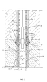
- FIG. 2 shows a detailed view of the wellbore 1 and the production tubing string 22 in the formation 18.
- a cemented wall 28 is built against the borehole wall 10a and perforations 20 extend outwardly through said cemented wall into the formation 18.
- a sand control apparatus is arranged in a portion of the borehole 10 located in the formation 18.
- the sand control apparatus comprises a control screen 30 and a plurality of control particles 32 arranged between the cemented wall 28 and said control screen 30.
- the wellbore 1 may be deprived of cemented wall and be thus an open wellbore 1.
- control particles 32 of a specific size designed to prevent the passage of formation sand and/or fines from the formation 18 to the production flowbore 26.
- control particles 32 constitute a barrier or filter to migrating sand or formation particles while still permitting fluid flow from the formation 18.
- the control screen 30 and the control particles 32 allow stabilizing the formation 18 while causing minimal impairment to well productivity.
- control particles 32 could be used for example as proppant control particles.
- a proppant is a solid material, typically treated sand or man-made ceramic materials, designed to keep an induced hydraulic fracture open, during or following a fracturing treatment.
- sand control screens In addition to the use of sand control screens, other types of sand control equipment known from the person skilled in the art may be used in the borehole 10, including liners (e.g., slotted liners, perforated liners, etc.), combinations of liners and screens, and other suitable apparatus.
- liners e.g., slotted liners, perforated liners, etc.
- a cylindrical metallic casing could also be installed in the borehole 10 between the control screen 30 and the wall 10a of the borehole 10.
- control particles 32 A wide range of sizes and screen configurations are available to suit the characteristics of the control particles 32 used. Similarly, a wide range of sizes of control particles 32 are available to suit the characteristics of the formation sand or reservoir particles.
- Control particles 32 may be for example gravels, sintered bauxite or ceramics such as e.g. CARBOLITE ® . Ceramic control particles have a bulk density and specific gravity similar to sand, yet providing high flow capacity for enhanced production rates. Standard sizes for ceramic control particles are: 12/18, 16/20, 20/40 and 30/50 Mesh.
- FIG. 3 an exemplary embodiment of an arrangement of control particles 32 is shown.
- a significant amount of blocking elements 35 such as e.g. mineral deposits, fines and/or formation sand grains, is located on or in between control particles 32 prior to applying the method according to the invention.
- the system 5 comprises a shock wave generation device 36, a wireline 37 coupled to said shock wave generation device 36 for raising and lowering said shock wave generation device 36 in the production tubing string 22 nearby control screen 30 and control particles 32, a voltage source 38 located external of the borehole 10 and an electrical circuit within said wireline 37 for connecting said voltage source 38 to the shock wave generation device 36.
- the shock wave generation device 36 is a source of electrohydraulic energy, which comprises a membrane 40 and an electrical discharge unit 42.
- the membrane 40 delimits a chamber 44 which is filled with a shock wave transmitting liquid 46.
- Such a membrane 40 isolates the liquid 46 in the chamber 44 from the production tubing string 22 while maintaining acoustic coupling with said production tubing string 22, improving the propagation of shockwaves while preventing external fluids from damaging the electrical discharge unit 42.
- the membrane 40 is flexible in order to an efficient propagation of shock waves in many directions and prevent shock waves to bounce on it, allowing therefore an efficient conduction of the shock wave toward control particles 32, in particular toward areas of control particles 32 which are accessible with difficulty or inaccessible to mechanical means such as e.g. brushes or chemical means such as e.g. acid.
- the membrane 40 may be made of fluorine rubber or fluoroelastomer with a relative elongation of at least 150 %, preferably at least 200% and being operable between -35°C and 250°C.
- the electrical discharge unit 42 is configured for generating a series of electrical discharges that propagate a series of shock waves into the shock wave transmitting liquid 46 and through the membrane 40 toward the control particles 32 for removing blocking elements 35 from said control particles 32.
- the electrical discharge unit 42 may be configured to propagate shock waves radially or in a predetermined direction.
- the electrical discharge unit 42 comprises a power conversion unit 48, a power storage unit 50, a discharge control unit 52 and a discharge system 54.
- the discharge system 54 comprises a first electrode 56 and a second electrode 58 configured for triggering an electrical discharge.
- the discharge system 54 comprises a plurality of capacitors (not represented) for storage of electrical energy configured for generating one or a plurality of electrical discharges into the shock wave transmitting liquid 46.
- the chamber 44 is delimited by the membrane 40 around the discharge system 54 which is filled with the shock wave transmitting liquid 46, allowing transmitting shock waves through the membrane 40 toward the control particles 32.
- the power conversion unit 48 comprises suitable circuitry for charging of the capacitors in the power storage unit 50. Timing of the discharge of the energy in the power from the power storage unit 50 through the discharge system 54 is accomplished using the discharge control unit 52.
- the discharge control unit 52 is a switch, which discharges when the voltage reaches a predefined threshold. Upon discharge of the capacitors in the power storage section through the first electrodes 56 and the second electrode 58 of the discharge control unit 52, electrohydraulic shock waves 60 (in reference to FIG. 2 ) are transmitted to the control particles 32 for cleaning said control particle 32 .
- the invention is describes in its application to removing deposits, in particular mineral deposits, and/or fines from control particles 32 and/or or redistributing deposits and/or fines located in between control particles 32, said control particles 32 being arranged in annulus 24 and perforations 20 for preventing the passage of sand formation when collecting formation fluids.
- FIG. 5 illustrates an embodiment of the method for cleaning control particles 32 arranged in a borehole 10 of a subterranean formation 18 according to the invention.
- the sand control apparatus Prior to operate the method according to the invention, the sand control apparatus is at least partially blocked with blocking elements 35 (as described here above in reference to FIG. 3 ).
- a series of shock waves is generated into the control screen 30 nearby the control particles 32.
- the series of shock waves is generated into the shock wave transmitting liquid 46 of the shock wave generating device 36.
- a second step S2 the series of shock waves propagates through the membrane 40 toward the control screen 30 and control particles 32 for removing blocking elements 35 located on or in between said control particles 32.
- the series of shock waves comprises at least ten shock waves, for example propagated at a periodic interval of time, e.g. every 5 to 20 seconds.
- a plurality of series may be advantageously repeated at different heights in the production tubing string 22 to remove blocking elements 35 in areas which would be inaccessible to mechanical or chemical means such as e.g. acid.
- FIG. 6 shows the variation of pressure with time nearby control particles 32.
- the pressure generated by the shock wave increases in a very short time dT, e.g. a few microseconds, until a maximum P1.
- dT very short time
- P1 maximum pressure
- Such a peak phase characterizes a compression of blocking elements 35.
- the pressure generated by the shock wave decreases to a negative value P2 for a significant amount of time, e.g. a few milliseconds.
- This second phase characterizes a traction effort applied on blocking elements, which allows breaking said blocking elements 35, in particular in areas which are accessible with difficulty or inaccessible to mechanical or chemical means.
- Such an traction effort is improved by the quality of propagation of the shock wave trough the shock wave transmitting liquid 46 and the membrane 40, allowing removing blocking elements 35 efficiently.
- Embodiments include many additional standard components or equipment that enables and makes operable the described device, process, method and system.
- control and performance of portions of or entire steps of a process or method can occur through human interaction, pre-programmed computer control and response systems, or combinations thereof.
- This method shows good results as at least 80 % of blocking elements 35 are removed from or between control particles 32.
- the invention is not limited to the described embodiment and can be applied to all type of formation fluids or gases transportation means.
Landscapes
- Life Sciences & Earth Sciences (AREA)
- Engineering & Computer Science (AREA)
- Geology (AREA)
- Mining & Mineral Resources (AREA)
- Physics & Mathematics (AREA)
- Environmental & Geological Engineering (AREA)
- Fluid Mechanics (AREA)
- General Life Sciences & Earth Sciences (AREA)
- Geochemistry & Mineralogy (AREA)
- Physical Or Chemical Processes And Apparatus (AREA)
- Earth Drilling (AREA)
Priority Applications (1)
| Application Number | Priority Date | Filing Date | Title |
|---|---|---|---|
| EP14178419.9A EP2977545B1 (fr) | 2014-07-24 | 2014-07-24 | Procédé et dispositif de nettoyage de particules de commande dans un puits de forage |
Applications Claiming Priority (1)
| Application Number | Priority Date | Filing Date | Title |
|---|---|---|---|
| EP14178419.9A EP2977545B1 (fr) | 2014-07-24 | 2014-07-24 | Procédé et dispositif de nettoyage de particules de commande dans un puits de forage |
Publications (2)
| Publication Number | Publication Date |
|---|---|
| EP2977545A1 true EP2977545A1 (fr) | 2016-01-27 |
| EP2977545B1 EP2977545B1 (fr) | 2019-06-05 |
Family
ID=51224785
Family Applications (1)
| Application Number | Title | Priority Date | Filing Date |
|---|---|---|---|
| EP14178419.9A Active EP2977545B1 (fr) | 2014-07-24 | 2014-07-24 | Procédé et dispositif de nettoyage de particules de commande dans un puits de forage |
Country Status (1)
| Country | Link |
|---|---|
| EP (1) | EP2977545B1 (fr) |
Cited By (4)
| Publication number | Priority date | Publication date | Assignee | Title |
|---|---|---|---|---|
| US20150308233A1 (en) * | 2014-04-28 | 2015-10-29 | Blue Spark Energy Inc. | Method and device for removing deposits from a formation fluid or gas transportation means |
| EP3461990A1 (fr) * | 2017-10-02 | 2019-04-03 | Blue Spark Energy Inc. | Dispositif et procédé pour nettoyer un équipement de forage |
| US20190100981A1 (en) * | 2017-10-02 | 2019-04-04 | Blue Spark Energy Inc. | Device and method for cleaning a wellbore equipment |
| CN113789694A (zh) * | 2021-08-21 | 2021-12-14 | 杭州萧山水利建筑工程有限公司 | 一种装配式环保透水混凝土道路 |
Citations (10)
| Publication number | Priority date | Publication date | Assignee | Title |
|---|---|---|---|---|
| US4345650A (en) | 1980-04-11 | 1982-08-24 | Wesley Richard H | Process and apparatus for electrohydraulic recovery of crude oil |
| US4997044A (en) * | 1989-12-01 | 1991-03-05 | Stack Walter E | Apparatus for generating hydraulic shock waves in a well |
| US5004050A (en) * | 1988-05-20 | 1991-04-02 | Sizonenko Olga N | Method for well stimulation in the process of oil production and device for carrying same into effect |
| US5579845A (en) * | 1995-02-07 | 1996-12-03 | William C. Frazier | Method for improved water well production |
| US6227293B1 (en) | 2000-02-09 | 2001-05-08 | Conoco Inc. | Process and apparatus for coupled electromagnetic and acoustic stimulation of crude oil reservoirs using pulsed power electrohydraulic and electromagnetic discharge |
| US20020153135A1 (en) * | 2001-04-24 | 2002-10-24 | Layne Christensen Company | Method and apparatus for stimulating well production |
| US20050061503A1 (en) | 2002-09-27 | 2005-03-24 | Misselbrook John Gordon | Method for cleaning gravel packs |
| US20070187090A1 (en) | 2006-02-15 | 2007-08-16 | Halliburton Energy Services, Inc. | Methods of cleaning sand control screens and gravel packs |
| US7896080B1 (en) | 2006-09-08 | 2011-03-01 | Larry Watters | Method of improving hydrocarbon production from a gravel packed oil and gas well |
| US20140008073A1 (en) * | 2011-03-14 | 2014-01-09 | Total S.A. | Electrical and static fracturing of a reservoir |
Family Cites Families (1)
| Publication number | Priority date | Publication date | Assignee | Title |
|---|---|---|---|---|
| EP2940244B1 (fr) * | 2014-04-28 | 2019-07-24 | Blue Spark Energy Inc. | Procédé et dispositif permettant d'éliminer la formation de dépôts d'un moyen de transport de fluide ou de gaz |
-
2014
- 2014-07-24 EP EP14178419.9A patent/EP2977545B1/fr active Active
Patent Citations (10)
| Publication number | Priority date | Publication date | Assignee | Title |
|---|---|---|---|---|
| US4345650A (en) | 1980-04-11 | 1982-08-24 | Wesley Richard H | Process and apparatus for electrohydraulic recovery of crude oil |
| US5004050A (en) * | 1988-05-20 | 1991-04-02 | Sizonenko Olga N | Method for well stimulation in the process of oil production and device for carrying same into effect |
| US4997044A (en) * | 1989-12-01 | 1991-03-05 | Stack Walter E | Apparatus for generating hydraulic shock waves in a well |
| US5579845A (en) * | 1995-02-07 | 1996-12-03 | William C. Frazier | Method for improved water well production |
| US6227293B1 (en) | 2000-02-09 | 2001-05-08 | Conoco Inc. | Process and apparatus for coupled electromagnetic and acoustic stimulation of crude oil reservoirs using pulsed power electrohydraulic and electromagnetic discharge |
| US20020153135A1 (en) * | 2001-04-24 | 2002-10-24 | Layne Christensen Company | Method and apparatus for stimulating well production |
| US20050061503A1 (en) | 2002-09-27 | 2005-03-24 | Misselbrook John Gordon | Method for cleaning gravel packs |
| US20070187090A1 (en) | 2006-02-15 | 2007-08-16 | Halliburton Energy Services, Inc. | Methods of cleaning sand control screens and gravel packs |
| US7896080B1 (en) | 2006-09-08 | 2011-03-01 | Larry Watters | Method of improving hydrocarbon production from a gravel packed oil and gas well |
| US20140008073A1 (en) * | 2011-03-14 | 2014-01-09 | Total S.A. | Electrical and static fracturing of a reservoir |
Cited By (6)
| Publication number | Priority date | Publication date | Assignee | Title |
|---|---|---|---|---|
| US20150308233A1 (en) * | 2014-04-28 | 2015-10-29 | Blue Spark Energy Inc. | Method and device for removing deposits from a formation fluid or gas transportation means |
| US9890613B2 (en) * | 2014-04-28 | 2018-02-13 | Blue Spark Energy Inc. | Method and device for removing deposits from a formation fluid or gas transportation means |
| EP3461990A1 (fr) * | 2017-10-02 | 2019-04-03 | Blue Spark Energy Inc. | Dispositif et procédé pour nettoyer un équipement de forage |
| US20190100981A1 (en) * | 2017-10-02 | 2019-04-04 | Blue Spark Energy Inc. | Device and method for cleaning a wellbore equipment |
| US10865622B2 (en) * | 2017-10-02 | 2020-12-15 | Blue Spark Energy Inc. | Device and method for cleaning a wellbore equipment |
| CN113789694A (zh) * | 2021-08-21 | 2021-12-14 | 杭州萧山水利建筑工程有限公司 | 一种装配式环保透水混凝土道路 |
Also Published As
| Publication number | Publication date |
|---|---|
| EP2977545B1 (fr) | 2019-06-05 |
Similar Documents
| Publication | Publication Date | Title |
|---|---|---|
| US9810041B2 (en) | Method and device for cleaning control particles in a wellbore | |
| US7882895B2 (en) | Method for impulse stimulation of oil and gas well production | |
| US8640772B2 (en) | Enhanced geothermal systems and reservoir optimization | |
| US8082989B2 (en) | Method for impulse stimulation of oil and gas well production | |
| US10309202B2 (en) | Fracturing treatment of subterranean formations using shock waves | |
| CN102301088A (zh) | 增强注射作业并促进油气产出的方法 | |
| CN104420859B (zh) | 驱移水平井或斜井中的支撑剂至液力压裂裂缝中的方法 | |
| EP2977545B1 (fr) | Procédé et dispositif de nettoyage de particules de commande dans un puits de forage | |
| US9890613B2 (en) | Method and device for removing deposits from a formation fluid or gas transportation means | |
| RU2600249C1 (ru) | Способ и устройство воздействия на нефтенасыщенные пласты и призабойную зону горизонтальной скважины | |
| EP4634486A1 (fr) | Utilisation de résonateurs à ondes de pression dans des opérations de fond de trou | |
| US10865622B2 (en) | Device and method for cleaning a wellbore equipment | |
| EP2940244B1 (fr) | Procédé et dispositif permettant d'éliminer la formation de dépôts d'un moyen de transport de fluide ou de gaz | |
| US7059411B2 (en) | Process of using a propellant treatment and continuous foam removal of well debris and apparatus therefore | |
| US9567828B2 (en) | Apparatus and method for sealing a portion of a component disposed in a wellbore | |
| US20050045336A1 (en) | Propellant treatment and continuous foam removal of well debris | |
| US20160348475A1 (en) | Method for sealing an opening of a wellbore equipment | |
| EP3461990B1 (fr) | Dispositif et procédé pour nettoyer un équipement de forage | |
| EP3098379B1 (fr) | Procédé permettant de rendre étanche une ouverture d'un équipement de forage | |
| CA2447556C (fr) | Traitement par charge propulsive et evacuation continue des debris de puits a l'aide de mousse | |
| López–Bonetti et al. | Hydraulic fracture assisted with coiled tubing in unconventional wells: lessons learned and case histories from northern Mexico | |
| Pinto et al. | Coiled Tubing and a Fluidic Oscillator Used as an Aid for Selective Placement Technique to Wells in Huila, Colombia | |
| CA2438640A1 (fr) | Utilisation d'un propulsif combinee a une elimination continue des debris de puits a l'aide de mousse |
Legal Events
| Date | Code | Title | Description |
|---|---|---|---|
| PUAI | Public reference made under article 153(3) epc to a published international application that has entered the european phase |
Free format text: ORIGINAL CODE: 0009012 |
|
| AK | Designated contracting states |
Kind code of ref document: A1 Designated state(s): AL AT BE BG CH CY CZ DE DK EE ES FI FR GB GR HR HU IE IS IT LI LT LU LV MC MK MT NL NO PL PT RO RS SE SI SK SM TR |
|
| AX | Request for extension of the european patent |
Extension state: BA ME |
|
| 17P | Request for examination filed |
Effective date: 20160622 |
|
| RBV | Designated contracting states (corrected) |
Designated state(s): AL AT BE BG CH CY CZ DE DK EE ES FI FR GB GR HR HU IE IS IT LI LT LU LV MC MK MT NL NO PL PT RO RS SE SI SK SM TR |
|
| STAA | Information on the status of an ep patent application or granted ep patent |
Free format text: STATUS: EXAMINATION IS IN PROGRESS |
|
| 17Q | First examination report despatched |
Effective date: 20161222 |
|
| GRAP | Despatch of communication of intention to grant a patent |
Free format text: ORIGINAL CODE: EPIDOSNIGR1 |
|
| STAA | Information on the status of an ep patent application or granted ep patent |
Free format text: STATUS: GRANT OF PATENT IS INTENDED |
|
| RIC1 | Information provided on ipc code assigned before grant |
Ipc: E21B 37/08 20060101AFI20190301BHEP Ipc: B08B 7/02 20060101ALI20190301BHEP |
|
| INTG | Intention to grant announced |
Effective date: 20190322 |
|
| RIN1 | Information on inventor provided before grant (corrected) |
Inventor name: CARROLL, SHAWN Inventor name: PARKER, TODD Inventor name: SKIBISNKI, DAN |
|
| GRAS | Grant fee paid |
Free format text: ORIGINAL CODE: EPIDOSNIGR3 |
|
| GRAA | (expected) grant |
Free format text: ORIGINAL CODE: 0009210 |
|
| STAA | Information on the status of an ep patent application or granted ep patent |
Free format text: STATUS: THE PATENT HAS BEEN GRANTED |
|
| AK | Designated contracting states |
Kind code of ref document: B1 Designated state(s): AL AT BE BG CH CY CZ DE DK EE ES FI FR GB GR HR HU IE IS IT LI LT LU LV MC MK MT NL NO PL PT RO RS SE SI SK SM TR |
|
| REG | Reference to a national code |
Ref country code: GB Ref legal event code: FG4D |
|
| REG | Reference to a national code |
Ref country code: CH Ref legal event code: EP |
|
| REG | Reference to a national code |
Ref country code: AT Ref legal event code: REF Ref document number: 1140151 Country of ref document: AT Kind code of ref document: T Effective date: 20190615 |
|
| REG | Reference to a national code |
Ref country code: IE Ref legal event code: FG4D |
|
| REG | Reference to a national code |
Ref country code: DE Ref legal event code: R096 Ref document number: 602014047755 Country of ref document: DE |
|
| REG | Reference to a national code |
Ref country code: NO Ref legal event code: T2 Effective date: 20190605 |
|
| REG | Reference to a national code |
Ref country code: NL Ref legal event code: MP Effective date: 20190605 |
|
| REG | Reference to a national code |
Ref country code: LT Ref legal event code: MG4D |
|
| PG25 | Lapsed in a contracting state [announced via postgrant information from national office to epo] |
Ref country code: AL Free format text: LAPSE BECAUSE OF FAILURE TO SUBMIT A TRANSLATION OF THE DESCRIPTION OR TO PAY THE FEE WITHIN THE PRESCRIBED TIME-LIMIT Effective date: 20190605 Ref country code: ES Free format text: LAPSE BECAUSE OF FAILURE TO SUBMIT A TRANSLATION OF THE DESCRIPTION OR TO PAY THE FEE WITHIN THE PRESCRIBED TIME-LIMIT Effective date: 20190605 Ref country code: SE Free format text: LAPSE BECAUSE OF FAILURE TO SUBMIT A TRANSLATION OF THE DESCRIPTION OR TO PAY THE FEE WITHIN THE PRESCRIBED TIME-LIMIT Effective date: 20190605 Ref country code: HR Free format text: LAPSE BECAUSE OF FAILURE TO SUBMIT A TRANSLATION OF THE DESCRIPTION OR TO PAY THE FEE WITHIN THE PRESCRIBED TIME-LIMIT Effective date: 20190605 Ref country code: LT Free format text: LAPSE BECAUSE OF FAILURE TO SUBMIT A TRANSLATION OF THE DESCRIPTION OR TO PAY THE FEE WITHIN THE PRESCRIBED TIME-LIMIT Effective date: 20190605 Ref country code: FI Free format text: LAPSE BECAUSE OF FAILURE TO SUBMIT A TRANSLATION OF THE DESCRIPTION OR TO PAY THE FEE WITHIN THE PRESCRIBED TIME-LIMIT Effective date: 20190605 |
|
| PG25 | Lapsed in a contracting state [announced via postgrant information from national office to epo] |
Ref country code: LV Free format text: LAPSE BECAUSE OF FAILURE TO SUBMIT A TRANSLATION OF THE DESCRIPTION OR TO PAY THE FEE WITHIN THE PRESCRIBED TIME-LIMIT Effective date: 20190605 Ref country code: RS Free format text: LAPSE BECAUSE OF FAILURE TO SUBMIT A TRANSLATION OF THE DESCRIPTION OR TO PAY THE FEE WITHIN THE PRESCRIBED TIME-LIMIT Effective date: 20190605 Ref country code: BG Free format text: LAPSE BECAUSE OF FAILURE TO SUBMIT A TRANSLATION OF THE DESCRIPTION OR TO PAY THE FEE WITHIN THE PRESCRIBED TIME-LIMIT Effective date: 20190905 Ref country code: GR Free format text: LAPSE BECAUSE OF FAILURE TO SUBMIT A TRANSLATION OF THE DESCRIPTION OR TO PAY THE FEE WITHIN THE PRESCRIBED TIME-LIMIT Effective date: 20190906 |
|
| REG | Reference to a national code |
Ref country code: AT Ref legal event code: MK05 Ref document number: 1140151 Country of ref document: AT Kind code of ref document: T Effective date: 20190605 |
|
| PG25 | Lapsed in a contracting state [announced via postgrant information from national office to epo] |
Ref country code: PT Free format text: LAPSE BECAUSE OF FAILURE TO SUBMIT A TRANSLATION OF THE DESCRIPTION OR TO PAY THE FEE WITHIN THE PRESCRIBED TIME-LIMIT Effective date: 20191007 Ref country code: SK Free format text: LAPSE BECAUSE OF FAILURE TO SUBMIT A TRANSLATION OF THE DESCRIPTION OR TO PAY THE FEE WITHIN THE PRESCRIBED TIME-LIMIT Effective date: 20190605 Ref country code: EE Free format text: LAPSE BECAUSE OF FAILURE TO SUBMIT A TRANSLATION OF THE DESCRIPTION OR TO PAY THE FEE WITHIN THE PRESCRIBED TIME-LIMIT Effective date: 20190605 Ref country code: AT Free format text: LAPSE BECAUSE OF FAILURE TO SUBMIT A TRANSLATION OF THE DESCRIPTION OR TO PAY THE FEE WITHIN THE PRESCRIBED TIME-LIMIT Effective date: 20190605 Ref country code: CZ Free format text: LAPSE BECAUSE OF FAILURE TO SUBMIT A TRANSLATION OF THE DESCRIPTION OR TO PAY THE FEE WITHIN THE PRESCRIBED TIME-LIMIT Effective date: 20190605 Ref country code: NL Free format text: LAPSE BECAUSE OF FAILURE TO SUBMIT A TRANSLATION OF THE DESCRIPTION OR TO PAY THE FEE WITHIN THE PRESCRIBED TIME-LIMIT Effective date: 20190605 Ref country code: RO Free format text: LAPSE BECAUSE OF FAILURE TO SUBMIT A TRANSLATION OF THE DESCRIPTION OR TO PAY THE FEE WITHIN THE PRESCRIBED TIME-LIMIT Effective date: 20190605 |
|
| REG | Reference to a national code |
Ref country code: DE Ref legal event code: R119 Ref document number: 602014047755 Country of ref document: DE |
|
| PG25 | Lapsed in a contracting state [announced via postgrant information from national office to epo] |
Ref country code: SM Free format text: LAPSE BECAUSE OF FAILURE TO SUBMIT A TRANSLATION OF THE DESCRIPTION OR TO PAY THE FEE WITHIN THE PRESCRIBED TIME-LIMIT Effective date: 20190605 Ref country code: IT Free format text: LAPSE BECAUSE OF FAILURE TO SUBMIT A TRANSLATION OF THE DESCRIPTION OR TO PAY THE FEE WITHIN THE PRESCRIBED TIME-LIMIT Effective date: 20190605 Ref country code: IS Free format text: LAPSE BECAUSE OF FAILURE TO SUBMIT A TRANSLATION OF THE DESCRIPTION OR TO PAY THE FEE WITHIN THE PRESCRIBED TIME-LIMIT Effective date: 20191005 |
|
| REG | Reference to a national code |
Ref country code: CH Ref legal event code: PL |
|
| PG25 | Lapsed in a contracting state [announced via postgrant information from national office to epo] |
Ref country code: TR Free format text: LAPSE BECAUSE OF FAILURE TO SUBMIT A TRANSLATION OF THE DESCRIPTION OR TO PAY THE FEE WITHIN THE PRESCRIBED TIME-LIMIT Effective date: 20190605 Ref country code: MC Free format text: LAPSE BECAUSE OF FAILURE TO SUBMIT A TRANSLATION OF THE DESCRIPTION OR TO PAY THE FEE WITHIN THE PRESCRIBED TIME-LIMIT Effective date: 20190605 |
|
| PLBE | No opposition filed within time limit |
Free format text: ORIGINAL CODE: 0009261 |
|
| STAA | Information on the status of an ep patent application or granted ep patent |
Free format text: STATUS: NO OPPOSITION FILED WITHIN TIME LIMIT |
|
| REG | Reference to a national code |
Ref country code: BE Ref legal event code: MM Effective date: 20190731 |
|
| PG25 | Lapsed in a contracting state [announced via postgrant information from national office to epo] |
Ref country code: PL Free format text: LAPSE BECAUSE OF FAILURE TO SUBMIT A TRANSLATION OF THE DESCRIPTION OR TO PAY THE FEE WITHIN THE PRESCRIBED TIME-LIMIT Effective date: 20190605 Ref country code: DE Free format text: LAPSE BECAUSE OF NON-PAYMENT OF DUE FEES Effective date: 20200201 Ref country code: DK Free format text: LAPSE BECAUSE OF FAILURE TO SUBMIT A TRANSLATION OF THE DESCRIPTION OR TO PAY THE FEE WITHIN THE PRESCRIBED TIME-LIMIT Effective date: 20190605 |
|
| 26N | No opposition filed |
Effective date: 20200306 |
|
| PG25 | Lapsed in a contracting state [announced via postgrant information from national office to epo] |
Ref country code: LI Free format text: LAPSE BECAUSE OF NON-PAYMENT OF DUE FEES Effective date: 20190731 Ref country code: SI Free format text: LAPSE BECAUSE OF FAILURE TO SUBMIT A TRANSLATION OF THE DESCRIPTION OR TO PAY THE FEE WITHIN THE PRESCRIBED TIME-LIMIT Effective date: 20190605 Ref country code: BE Free format text: LAPSE BECAUSE OF NON-PAYMENT OF DUE FEES Effective date: 20190731 Ref country code: LU Free format text: LAPSE BECAUSE OF NON-PAYMENT OF DUE FEES Effective date: 20190724 Ref country code: CH Free format text: LAPSE BECAUSE OF NON-PAYMENT OF DUE FEES Effective date: 20190731 |
|
| PG25 | Lapsed in a contracting state [announced via postgrant information from national office to epo] |
Ref country code: IE Free format text: LAPSE BECAUSE OF NON-PAYMENT OF DUE FEES Effective date: 20190724 |
|
| PG25 | Lapsed in a contracting state [announced via postgrant information from national office to epo] |
Ref country code: CY Free format text: LAPSE BECAUSE OF FAILURE TO SUBMIT A TRANSLATION OF THE DESCRIPTION OR TO PAY THE FEE WITHIN THE PRESCRIBED TIME-LIMIT Effective date: 20190605 |
|
| PG25 | Lapsed in a contracting state [announced via postgrant information from national office to epo] |
Ref country code: HU Free format text: LAPSE BECAUSE OF FAILURE TO SUBMIT A TRANSLATION OF THE DESCRIPTION OR TO PAY THE FEE WITHIN THE PRESCRIBED TIME-LIMIT; INVALID AB INITIO Effective date: 20140724 Ref country code: MT Free format text: LAPSE BECAUSE OF FAILURE TO SUBMIT A TRANSLATION OF THE DESCRIPTION OR TO PAY THE FEE WITHIN THE PRESCRIBED TIME-LIMIT Effective date: 20190605 |
|
| PG25 | Lapsed in a contracting state [announced via postgrant information from national office to epo] |
Ref country code: MK Free format text: LAPSE BECAUSE OF FAILURE TO SUBMIT A TRANSLATION OF THE DESCRIPTION OR TO PAY THE FEE WITHIN THE PRESCRIBED TIME-LIMIT Effective date: 20190605 |
|
| PGFP | Annual fee paid to national office [announced via postgrant information from national office to epo] |
Ref country code: NO Payment date: 20250725 Year of fee payment: 12 |
|
| PGFP | Annual fee paid to national office [announced via postgrant information from national office to epo] |
Ref country code: GB Payment date: 20250722 Year of fee payment: 12 |
|
| PGFP | Annual fee paid to national office [announced via postgrant information from national office to epo] |
Ref country code: FR Payment date: 20250721 Year of fee payment: 12 |