EP2977559B1 - Stator einer axialen strömungsmaschine und zugehörige strömungsmaschine - Google Patents
Stator einer axialen strömungsmaschine und zugehörige strömungsmaschine Download PDFInfo
- Publication number
- EP2977559B1 EP2977559B1 EP14178502.2A EP14178502A EP2977559B1 EP 2977559 B1 EP2977559 B1 EP 2977559B1 EP 14178502 A EP14178502 A EP 14178502A EP 2977559 B1 EP2977559 B1 EP 2977559B1
- Authority
- EP
- European Patent Office
- Prior art keywords
- lattice
- stator
- wall
- accordance
- turbomachine
- Prior art date
- Legal status (The legal status is an assumption and is not a legal conclusion. Google has not performed a legal analysis and makes no representation as to the accuracy of the status listed.)
- Active
Links
Images

Classifications
-
- F—MECHANICAL ENGINEERING; LIGHTING; HEATING; WEAPONS; BLASTING
- F04—POSITIVE - DISPLACEMENT MACHINES FOR LIQUIDS; PUMPS FOR LIQUIDS OR ELASTIC FLUIDS
- F04D—NON-POSITIVE-DISPLACEMENT PUMPS
- F04D29/00—Details, component parts, or accessories
- F04D29/60—Mounting; Assembling; Disassembling
- F04D29/64—Mounting; Assembling; Disassembling of axial pumps
- F04D29/644—Mounting; Assembling; Disassembling of axial pumps especially adapted for elastic fluid pumps
-
- F—MECHANICAL ENGINEERING; LIGHTING; HEATING; WEAPONS; BLASTING
- F01—MACHINES OR ENGINES IN GENERAL; ENGINE PLANTS IN GENERAL; STEAM ENGINES
- F01D—NON-POSITIVE DISPLACEMENT MACHINES OR ENGINES, e.g. STEAM TURBINES
- F01D11/00—Preventing or minimising internal leakage of working-fluid, e.g. between stages
- F01D11/001—Preventing or minimising internal leakage of working-fluid, e.g. between stages for sealing space between stator blade and rotor
-
- F—MECHANICAL ENGINEERING; LIGHTING; HEATING; WEAPONS; BLASTING
- F01—MACHINES OR ENGINES IN GENERAL; ENGINE PLANTS IN GENERAL; STEAM ENGINES
- F01D—NON-POSITIVE DISPLACEMENT MACHINES OR ENGINES, e.g. STEAM TURBINES
- F01D9/00—Stators
- F01D9/02—Nozzles; Nozzle boxes; Stator blades; Guide conduits, e.g. individual nozzles
- F01D9/04—Nozzles; Nozzle boxes; Stator blades; Guide conduits, e.g. individual nozzles forming ring or sector
- F01D9/042—Nozzles; Nozzle boxes; Stator blades; Guide conduits, e.g. individual nozzles forming ring or sector fixing blades to stators
-
- F—MECHANICAL ENGINEERING; LIGHTING; HEATING; WEAPONS; BLASTING
- F04—POSITIVE - DISPLACEMENT MACHINES FOR LIQUIDS; PUMPS FOR LIQUIDS OR ELASTIC FLUIDS
- F04D—NON-POSITIVE-DISPLACEMENT PUMPS
- F04D19/00—Axial-flow pumps
- F04D19/02—Multi-stage pumps
- F04D19/022—Multi-stage pumps with concentric rows of vanes
-
- F—MECHANICAL ENGINEERING; LIGHTING; HEATING; WEAPONS; BLASTING
- F04—POSITIVE - DISPLACEMENT MACHINES FOR LIQUIDS; PUMPS FOR LIQUIDS OR ELASTIC FLUIDS
- F04D—NON-POSITIVE-DISPLACEMENT PUMPS
- F04D29/00—Details, component parts, or accessories
- F04D29/08—Sealings
- F04D29/083—Sealings especially adapted for elastic fluid pumps
-
- F—MECHANICAL ENGINEERING; LIGHTING; HEATING; WEAPONS; BLASTING
- F04—POSITIVE - DISPLACEMENT MACHINES FOR LIQUIDS; PUMPS FOR LIQUIDS OR ELASTIC FLUIDS
- F04D—NON-POSITIVE-DISPLACEMENT PUMPS
- F04D29/00—Details, component parts, or accessories
- F04D29/08—Sealings
- F04D29/10—Shaft sealings
- F04D29/102—Shaft sealings especially adapted for elastic fluid pumps
-
- F—MECHANICAL ENGINEERING; LIGHTING; HEATING; WEAPONS; BLASTING
- F04—POSITIVE - DISPLACEMENT MACHINES FOR LIQUIDS; PUMPS FOR LIQUIDS OR ELASTIC FLUIDS
- F04D—NON-POSITIVE-DISPLACEMENT PUMPS
- F04D29/00—Details, component parts, or accessories
- F04D29/40—Casings; Connections of working fluid
- F04D29/52—Casings; Connections of working fluid for axial pumps
- F04D29/54—Fluid-guiding means, e.g. diffusers
- F04D29/541—Specially adapted for elastic fluid pumps
- F04D29/542—Bladed diffusers
Definitions
- the invention relates to a stator stage of axial turbomachine. More specifically, the invention relates to the attachment between a shell and a stator blade of axial turbomachine. The invention also relates to an axial turbomachine provided with a stator blade.
- a turbomachine offers mechanical work thanks to the gas flows that pass through it. These flows are guided by casings and series of internal ferrules.
- the inner shells are generally connected to the casing of the turbomachine via the stator vanes.
- the latter have internal ends with attachment portions to which the ferrules are connected. For example, it is known to anchor a ferrule to an annular row of vanes with the aid of a retention rod.
- the document EP 2 735 707 A1 discloses an axial turbomachine compressor stator.
- the rectifier comprises an outer casing, an annular array of vanes extending radially from the casing, and an inner ferrule connected to the inner ends of the vanes. These blade tips each have a retention hook in which is engaged a retention rod.
- the rod and the hooks are embedded in an abradable layer applied inside the blade, which allows the retention of the ferrule.
- the retention provided by this architecture is strong; it is particularly resistant to ingestions. However, it requires the addition of a retention rod that increases assembly costs and weighs down the rectifier. In the context of a segmented ferrule, the ferrule can tilt around the rod. The abradable wrapping wand at the rod is then strongly stressed and can degrade.
- the object of the invention is to solve at least one of the problems posed by the prior art. More specifically, the invention aims to improve the anchoring between a blade and a wall. The invention also aims to reduce the costs of assembling a stator with a wall connected to blades while improving anchoring and optimizing the distribution of forces between a blade and a wall.
- the subject of the invention is an axial turbomachine stator, in particular a compressor, the stator comprising: a circular or arcuate wall, the wall comprising a guide surface intended to guide a flow of the turbomachine; a circular or semicircular array of stator vanes, at least one of the stator vanes comprising a blade for extending radially in the flow from the guide surface and an anchor portion extending from the guide surface to the radially opposite of the blade; remarkable in that the anchoring portion of the blade comprises a lattice anchored to the wall so as to fix said blade to the wall via the lattice.
- the lattice is a three-dimensional lattice with intersecting rods and joined to each other so as to form meshes, the lattice comprising several meshes according to the thickness and / or the length of the blade and or in the radial direction.
- the at least one blade comprises a leading edge, a trailing edge, an intrados surface and an extrados surface, the intrados surface and the extrados surface extending from the leading edge to the upper surface. trailing edge; and the mesh extending from the leading edge to the trailing edge of the blade, and from the intrados surface to the extrados surface.
- the wall is an inner ferrule or an inner ferrule segment, preferably the inner ferrule and / or the wall is made of an organic matrix composite material.
- the wall comprises at least one opening in which the anchoring portion is arranged, preferably the mesh projects radially beyond the opening, more preferably the mesh is at a distance radially from the opening.
- the wall is made of material and is formed of a material that fills the lattice.
- the stator comprises a seal placed against the wall opposite the radially of the guide surface, the mesh being at least partially anchored in the radial thickness of the seal, possibly the seal comprises a matrix and balls in contact with the mesh.
- the seal comprises a layer of abradable material intended to cooperate by abrasion with the rotor of the turbomachine, the lattice being at least partially disposed in the radial thickness of the abradable layer, optionally the Abradable layer comprises a silicone material.
- the lattice extends over the majority of the axial length of the wall and / or the radial height of the wall.
- the blade comprises a solid body which extends over most of its radial height, preferably at least over its entire radial height.
- the mesh comprises a compactness of less than 60%, preferably less than 30%, more preferably less than 10%.
- the anchoring portion is a first anchoring portion
- the lattice is a first lattice
- the wall is a first wall
- the at least one blade further comprising a second portion of anchoring with a second lattice radially opposite the first lattice with respect to the blade and anchored in a second wall which is concentric with the first wall.
- the blade comprises a fixing platform, possibly with a fixing pin, arranged radially opposite the mesh relative to the blade; preferably the stator comprises an outer casing, the platform being fixed to said outer casing.
- the blade, the lattice, and possibly the attachment platform are made of material and are produced by additive manufacturing, preferably based on titanium powder.
- the guide surface being at a height radially between the blade and the anchoring portion.
- At least one or each anchoring portion is joined to a blade.
- the wall comprises an upstream axial half and a downstream axial half, preferably the lattice is axially spaced from one of the axial halves, possibly spaced from the upstream half.
- the wall may be annular or generally tubular, or form an angular portion of a ring or tube.
- the anchoring portion comprises an array of channels passing through the anchoring portion and the mesh, optionally axially and / or laterally.
- the mesh comprises a regular mesh; or the mesh is variable, possibly the mesh densifies in the radial direction of the blade, or densifies in the vicinity of the leading edge or the trailing edge.
- the lattice and the wall are made of different materials.
- the mesh is filled with a polymeric material, such as an elastomeric resin.
- the mesh comprises at least one rod extending over the majority, preferably the entire length or width of the blade.
- the lattice comprises at least two sets, preferably at least three sets of parallel rods, each set comprising rods perpendicular to the rods of the other games.
- the mesh comprises at least four sets of parallel rods, each set comprising rods oriented at 60 ° with respect to the rods of the other games.
- the lattice extends over the majority, preferably over the whole, of the axial length and / or the thickness of the blade.
- the lattice in the state not anchored to the shell, is predominantly empty, preferably 75% empty, more preferably 90% empty.
- the compactness of the lattice is understood as the ratio between the volume that is occupied by the material forming the lattice and the total volume in which the lattice is disposed.
- the mesh is shorter axially than the opening or each opening.
- the blade and each anchoring portion form a radial stack.
- the subject of the invention is also a turbomachine, comprising a stator, which is remarkable in that the stator is in accordance with the invention.
- the wall comprises an upstream axial half and a downstream axial half, preferably the trellis is axially distant from the trunk. one of the axial halves, possibly at a distance from the upstream half.
- the invention makes it possible to improve the stability of the anchoring between a blade and a wall.
- the invention increases and distributes the contact surface between the anchoring portion and the wall; possibly via the joint, so that the Inclined and asymmetrical ferrules as on the first rectifier and on the last rectifier are more stable.
- the trellis distributes the forces between the dawn and the wall. Its lower compactness than that of the blade reduces the stator mass.
- the mesh forms a zone of less stiffness in the dawn, it is more flexible and can absorb, damping a shock by limiting the energy transmitted to the wall.
- the rods may be inclined relative to the radial direction to promote the radial elongation of the mesh and further reduce the energy transmitted in case of radial tearing force. In this way, retention and fixation become safer.
- inner or inner and outer or outer refer to a positioning relative to the axis of rotation of an axial turbomachine.
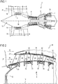
- the figure 1 represents in simplified manner an axial turbomachine. It is in this case a double-flow turbojet engine.
- the turbojet engine 2 comprises a first compression level, called a low-pressure compressor 4, a second compression level, called a high-pressure compressor 6, a combustion chamber 8 and one or more levels of turbines 10.
- a first compression level called a low-pressure compressor 4
- a second compression level called a high-pressure compressor 6
- a combustion chamber 8 and one or more levels of turbines 10.
- Reducing means can increase the speed of rotation transmitted to the compressors.
- the different turbine stages can each be connected to the compressor stages via concentric shafts.
- the latter comprise several rows of rotor blades associated with rows of stator vanes. The rotation of the rotor about its axis of rotation 14 thus makes it possible to generate an air flow and to compress it progressively until it reaches the combustion chamber 8.
- An inlet fan commonly referred to as fan or blower 16 is coupled to the rotor 12 and generates an air flow which splits into a primary flow 18 passing through the various aforementioned levels of the turbomachine, and a secondary flow 20 passing through an annular duct (partially shown) along the machine to then join the primary flow at the turbine outlet.
- the secondary stream can be accelerated to generate a reaction.
- the primary 18 and secondary 20 streams are annular flows, they are channeled by the casing of the turbomachine.
- the casing has cylindrical walls or ferrules which can be internal and external.
- the figure 2 is a sectional view of a compressor of an axial turbomachine 2 such as that of the figure 1 .
- the compressor may be a low-pressure compressor 4.
- the rotor 12 comprises several rows of rotor blades 24, in the occurrence three.
- the compressor 4 comprises several rectifiers, in this case four, each containing a row of stator vanes 26.
- the rectifiers are associated with the fan 16 or a row of rotor blades 24 to straighten the air flow, so to convert the speed of the flow into pressure.
- the compressor comprises a stator 28, possibly with an outer casing 30 which forms a partition supporting the separation spout 22.
- the partition supports the straighteners and annular layers of abradable materials disposed between the straighteners.
- the outer casing 30 can have a circular or annular shape and / or be formed of half-shells. It can be made of organic matrix composite material.
- the stator vanes 26 extend essentially radially from the partition of the outer casing 30, and can be fixed thereto by means of a through axis 32.
- the stator 28 comprises at least one wall 34, preferably several walls, such as inner rings 34, connected to the inner ends of the stator vanes 26 via anchoring portions.
- the wall 34 and the outer casing 30 are concentric.
- the anchoring portion of at least one stator vane 26 comprises a trellis 36, preferably each vane of a row of stator vanes 26 comprises an anchoring portion with a trellis 36, more preferably each stator vane 26 of at least one compressor 4 of the turbomachine comprises an anchoring portion with a mesh 36.
- the or each mesh 36 may be anchored or sealed to the wall 34 and / or to the inner shell 34.
- the stator 28 may comprise at least one seal 38 associated with the wall 34 or with each wall 34.
- the or at least one or each mesh 36 may be engaged in the seal 38 so as to anchor thereon and form a fastener between a stator blade 26 and the seal 38, and therefore between a stator vane 26 and the associated wall 34.
- the stator 28 shown is that of the compressor, but the invention could equally well be applied to a turbine stator or a turbomachine fan stator.
- the figure 3 represents the stator 28. There is an inner ferrule connected to the outer casing 30 via a stator blade 26, the mesh 36 of the blade is housed in the seal 38.
- the blade or each blade 26 comprises several radial portions, including a blade 40 extending radially in the flow and at least one anchoring portion 42.
- the blade 26 may optionally comprise a fastening platform 44 which forms a support for mounting.
- the platform 44 can be fixed to the outer casing 30 by means of its attachment pin 32 and a lockbolt 46, or have orifices coinciding with orifices of the outer casing. It may be a rectangular or parallelogram plate, and may be axially bordered by annular layers 48 of material abradable upstream and downstream.
- the platform 44 can be pressed against the outer casing 30, and / or can marry the outer casing 30, possibly over most of the length.
- the blade comprises a leading edge 50 connected to the trailing edge 52 by the intrados surface and the extrados surface. Dawn 26 may be curved, arched.
- the wall 34 may be the inner shell 34.
- the wall may comprise a guide surface 54 for guiding and delimiting a flow, such as the primary flow 18 of the turbomachine.
- This surface is generally annular, possibly substantially cylindrical, and can be segmented angularly. It extends all along the blade 40, and can extend beyond upstream and downstream.
- the wall 34 may comprise at least one opening 56 or a row of openings 56, each opening 56 receiving an anchoring portion 42 of blade 26 for attachment, in particular by anchoring.
- This attachment can be made in different ways, for example with a rod.
- the space between the opening 56 that the blade 26 passes through and the blade 40 can be closed with a silicone bead 58 to prevent leakage.
- the anchoring portion 42 may comprise a smooth portion to cooperate with the cord 58, the mesh being recessed radially with respect to the cord 58 and / or the opening 56.
- the blade 40 may extend radially outwards from the wall 34, from an opening 56.
- the wall may comprise pockets in which are anchored the trellises.
- the wall may have a web with a profile of revolution about the axis of rotation 14 in the shape of an inverted "U", with an axial portion, such as a sleeve, extended radially and delimited axially by radial portions.
- the veil can delimit an internal annular space.
- the wall 34 may be metallic or of organic matrix composite material to reduce the mass while optimizing rigidity.
- the wall 34 may be circular or form a circular arc. It can be a ferrule segment, that is to say have a shape of angular sector of a circle. In this case, a stator forms a circle through several segments put end-to-end.
- the stator 28 may comprise an annular or semi-annular seal 38, disposed against the wall 34, opposite the blade 40 relative to the guide surface 54.
- This seal 38 may be placed in the space annular wall of the wall 34, and can fill this space. It can wrap the ends of blades 26 or blades 40, and penetrate the or each anchoring portion 42.
- the seal 38 may be an elastomeric material that forms a matrix, such as silicone. It may be an annular layer of abradable material capable of crumbling in the event of contact with the rotor. It may comprise a matrix and particles, such as beads to promote the friable character of the seal. These balls can cooperate with the mesh and be configured to improve the anchoring.
- the or each mesh 36 may form the inner end, the tip of the blade 26.
- the or each mesh 36 may comprise rods 60 connected to each other. They can be straight or curved. They can be related to each other at their crossings.
- the rods 60 may form nodes at their intersections, possibly integrated into their sections.
- the mesh can be monobloc.
- the or each lattice 36 may be plane, and / or be formed along a left surface, for example parallel to the radial extension of the intrados surface or the extrados surface. It can be essentially bidirectional, for example by presenting flat meshes formed by its rods 60.
- the or each trellis can be three-dimensional, and present polyhedral meshes whose edges are formed by the rods 60.
- the meshes can be tetrahedra and / or cubes.
- Its rods 60 may be arranged in at least three directions, for example perpendicular to each other.
- the rods 60 may form sets of rods 60 having the same directions, and / or the same hangers.
- the or each mesh 36 may extend in the radial extension of the blade 40. It may extend between the leading edge 50 and the trailing edge 52, possibly it exceeds these edges. It may extend over the majority, preferably over the entire rope of the blade 40 at the guide surface 54.
- the or each mesh 36 may form several meshes along the blade 40, preferably at least ten meshes, more preferably at least fifty meshes.
- the or each mesh 36 may extend over the majority of the axial length of the wall 34.
- the axial elongation of the mesh 36 limits the tilting of the wall 34 relative to the blade 26, which may occur when the wall is short depending on the circumference.
- At least one rod 60 or a set of rods 60 may extend over the majority, possibly over the entire axial axis of the blade 40 and / or the anchoring portion 42.
- the or each trellis 36 may have a variable, heterogeneous mesh.
- the meshes can be tightened towards the blade 40, and possibly at the leading edge 50 and the trailing edge 52, for example to increase the efforts that can be transmitted to the rods 60 of the mesh 36 if ingested.
- the rods 60 can multiply and / or become thinner inwards.
- the compactness of each mesh 36 is less than 90%, preferably less than 50%, more preferably less than 5%. Compactness can double from one extreme to another. It can vary from 10%, preferably 30%. Alternatively, the mesh can be constant, homogeneous, possibly locally.
- the or each mesh 36 may be anchored in the gasket 38 and / or in the material itself forming the wall 34 and the guide surface 54.
- the mesh 36 is embedded in the material of the gasket 38, the rods 60 mingle with the gasket 38
- the seal 38 penetrates and occupies the meshes of the lattice so as to fill them. In this way, the seal 38 completely fills the space that the lattice, via its rods, does not occupy. All these properties of the seal are transposable to the material of the wall.
- the seal 38 may be molded on the wall, or projected.
- the mesh 36 may extend over most of the thickness of the revolution profile of the seal 36. This anchoring depth in the seal improves the retention, and the sealing effect.
- stator 28 of the turbomachine roughing a portion of the stator 28 of the turbomachine.
- stator vanes 26 fix a wall 34 to another wall 30 via mesh 36 integral with the seal 38.
- the row of blades may be an annular or semi-annular row; that is to say which describes an angular sector of a circle.
- Platforms 44 may be in contact with each other through their lateral edges to position the blades 26, and therefore the wall 34.
- At least one or each mesh 36 may extend radially in the extension of the thickness of the blade 40, the thickness that can be heard according to the circumference.
- At least one or each mesh 36 may extend the aerodynamic profile of the blade 40 at the guiding surface 54, possibly by reproducing the arched appearance of said profile.
- At least one or each mesh 36 may form several meshes according to the thickness of the blade 40, for example at least two, preferably at least five, more preferably at least ten meshes. At least one or each trellis 36 may have, radially at its maximum thickness, several rods which extend mainly axially. The mesh 36 may be wider than the blade 40 and less wide than the associated opening 56.
- the height of at least one or each mesh 36 may be greater than the maximum thickness of the blade 40, preferably at least three times greater. At least one or each mesh 36 may be spaced radially from the associated opening 56, and / or from the inner surface of the seal 38. At least one or each mesh 36 may have a general envelope whose surfaces are inclined with respect to the intrados surface 62 and the extrados surface 64 of the associated blade at the level of the guiding surface 54.
- each blade may comprise two lattices to be anchored to two walls.
- At least one or each blade 26 of the row may comprise a first internal anchoring portion anchored by its first lattice to the inner shell 34, and a second external anchoring portion anchored by a second lattice to the outer casing 30.
- the trellises are separated by the blade, each of them can be anchored in the thickness of the web of the outer casing, especially when the latter is molded.
- At least one or each blade 26, in particular its blade 40, its mesh 36 and possibly its platform 44; or its blade and lattices are made of material and can be made by additive manufacturing. They can be made of titanium powder or polymer so as to form a set of matter. The blade can form a monoblock element with a mixed structure, having a full blade and a partially empty lattice.
- the blade may be produced in the form of a row of vanes, with at least one or more anchor lattice vanes, and possibly other attachment means on the same radial side as the lattice on other vanes.
- the row of blades may have a common platform with several blades.
Landscapes
- Engineering & Computer Science (AREA)
- Mechanical Engineering (AREA)
- General Engineering & Computer Science (AREA)
- Structures Of Non-Positive Displacement Pumps (AREA)
Claims (15)
- Stator (28) einer axialen Turbomaschine (2), insbesondere eines Kompressors (4; 6), wobei der Stator Folgendes beinhaltet:- eine runde oder kreisbogenförmige Wandung (34), wobei die Wandung eine Leitfläche (54) beinhaltet, die für die Lenkung eines Stroms (18; 20) der Turbomaschine bestimmt ist;- eine kreis- oder halbkreisförmige Reihe von Statorschaufeln (26), wobei mindestens eine der Statorschaufeln (26) ein Blatt (49) aufweist, das dazu bestimmt ist, um sich von der Leitfläche (54) ausgehend radial im Strom zu erstrecken und einen Verankerungsabschnitt (42), der sich von der Leitfläche (54) aus erstreckt, die dem Schaufelblatt (40) radial gegenüberliegt;dadurch gekennzeichnet, dass:der Verankerungsabschnitt (42) der Schaufel ein Gitter (36) beinhaltet, das in der Weise an der Wandung (34) verankert ist, dass die genannte Schaufel (26) anhand des Gitters (36) an der Wandung (34) befestigt ist.
- Stator (28) nach Anspruch 1, dadurch gekennzeichnet, dass das Gitter (36) ein dreidimensionales Gitter mit gekreuzten Stäben (60) ist, die so miteinander verbunden sind, dass sie Maschen bilden, wobei das Gitter (36) mehrere Maschen entlang der Dicke und/oder Länge des Schaufelblattes (42) und/oder entlang der radialen Richtung beinhaltet.
- Stator (28) nach einem der Ansprüche 1 bis 2, dadurch gekennzeichnet, dass mindestens eine Schaufel eine Vorderkante (50), eine Hinterkante (52) und eine Druckseite (62) und eine Saugseite (64) beinhaltet, wobei sich die Druckseite und die Saugseite von der Vorderkante bis zur Hinterkante erstrecken; und sich das Gitter (36) von der Vorderkante bis zur Hinterkante der Schaufel (40) und von der Druckseite bis zur Saugseite erstreckt.
- Stator (28) nach einem der Ansprüche 1 bis 3, dadurch gekennzeichnet, dass die Wandung (34) ein Innenmantel (34) oder ein Segment des Innenmantels (34) ist, wobei der Innenmantel (34) und/oder die Wandung (34) aus einem Verbundmaterial mit organischer Matrix besteht.
- Stator (28) nach einem der Ansprüche 1 bis 4, dadurch gekennzeichnet, dass die Wandung mindestens eine Öffnung (56) beinhaltet, in der der Verankerungsabschnitt (42) angeordnet ist, wobei das Gitter (36) vorzugsweise die Öffnung (56) übersteht und sich das Gitter (36) noch bevorzugter in einem radialen Abstand von der Öffnung (56) befindet.
- Stator (28) nach einem der Ansprüche 1 bis 5, dadurch gekennzeichnet, dass die Wandung (36) aus dem gleichen Material besteht, das das Gitter (36) ausfüllt.
- Stator (28) nach einem der Ansprüche 1 bis 6, dadurch gekennzeichnet, dass er eine Dichtung (38) beinhaltet, die an der Wandung (34) anliegt, die radial der Leitfläche (54) gegenüberliegt, wobei das Gitter (36) mindestens teilweise in der radialen Dicke der Dichtung (38) verankert ist und die Dichtung (38) eventuell eine Matrix und Kugeln beinhaltet, die mit dem Gitter in Kontakt stehen.
- Stator (28) nach Anspruch 7, dadurch gekennzeichnet, dass die Dichtung (38) eine Schicht eines Abriebmaterials beinhaltet, die dazu bestimmt ist, um mittels Abrieb mit dem Rotor (12) der Turbomaschine (2) zusammenzuwirken, wobei das Gitter (38) mindestens teilweise in der radialen Dicke der Abriebschicht angeordnet ist und die Abriebschicht eventuell ein Silikonmaterial beinhaltet.
- Stator (28) nach einem der Ansprüche 1 bis 8, dadurch gekennzeichnet, dass sich das Gitter (36) über den größten Teil der axialen Länge der Wandung (34) und/oder der radialen Höhe der Wandung (34) erstreckt.
- Stator (28) nach einem der Ansprüche 1 bis 9, dadurch gekennzeichnet, dass die Schaufel (40) einen massiven Korpus beinhaltet, der sich über den größten Teil ihrer radialen Höhe erstreckt, vorzugsweise über mindestens ihre gesamte radiale Höhe.
- Stator (28) nach einem der Ansprüche 1 bis 10, dadurch gekennzeichnet, dass das Gitter (36) eine Kompaktheit von weniger als 60%, vorzugsweise von weniger als 30% und noch bevorzugter von weniger als 10% aufweist.
- Stator (28) nach einem der Ansprüche 1 bis 11, dadurch gekennzeichnet, dass der Verankerungsabschnitt (42) ein erster Verankerungsabschnitt und das Gitter (36) ein erstes Gitter und die Wandung eine erste Wandung ist, wobei die oder mindestens eine Schaufel außerdem einen zweiten Verankerungsabschnitt mit einem zweiten Gitter beinhaltet, das dem ersten Gitter im Verhältnis zur Schaufel radial gegenüber liegt und die Schaufel in einer zweiten Wandung verankert ist, die sich konzentrisch zur ersten Wandung verhält.
- Stator (28) nach einem der Ansprüche 1 bis 12, dadurch gekennzeichnet, dass die Schaufel (26) eine Befestigungsplattform (44) beinhaltet, eventuell mit einer Befestigungsachse (32), die dem Gitter (36) im Verhältnis zur Schaufel (40) radial gegenüberliegend angeordnet ist; wobei der Stator (28) vorzugsweise ein Außengehäuse (30) beinhaltet und die Plattform (44) an dem genannten Außengehäuse angebracht ist.
- Stator (28) nach einem der Ansprüche 1 bis 13, dadurch gekennzeichnet, dass die Schaufel (40), das Gitter (36) und eventuell die Befestigungsplattform (44) aus einem Material bestehen und durch additive Fertigung hergestellt werden, vorzugsweise auf der Basis von Titanpulver.
- Turbomaschine (2) mit einem Stator (28), dadurch gekennzeichnet, dass der Stator (28) einem der Ansprüche 1 bis 14 entspricht, wobei die Wandung (34) eventuell eine axiale obere Hälfte und eine axiale untere Hälfte beinhaltet und das Gitter vorzugsweise in axialem Abstand von einer der axialen Hälften und eventuell in Abstand von der unteren Hälfte angeordnet ist.
Priority Applications (5)
| Application Number | Priority Date | Filing Date | Title |
|---|---|---|---|
| EP14178502.2A EP2977559B1 (de) | 2014-07-25 | 2014-07-25 | Stator einer axialen strömungsmaschine und zugehörige strömungsmaschine |
| CA2897889A CA2897889A1 (en) | 2014-07-25 | 2015-07-20 | Blade with sealed lattice in a shroud of an axial turbomachine compressor |
| RU2015130479A RU2696177C2 (ru) | 2014-07-25 | 2015-07-23 | Осевая турбомашина |
| US14/808,256 US9957980B2 (en) | 2014-07-25 | 2015-07-24 | Vane with sealed lattice in a shroud of an axial turbomachine compressor |
| CN201510445706.3A CN105275869B (zh) | 2014-07-25 | 2015-07-27 | 轴流式涡轮机组压缩机的罩中具有密封格架的叶片 |
Applications Claiming Priority (1)
| Application Number | Priority Date | Filing Date | Title |
|---|---|---|---|
| EP14178502.2A EP2977559B1 (de) | 2014-07-25 | 2014-07-25 | Stator einer axialen strömungsmaschine und zugehörige strömungsmaschine |
Publications (2)
| Publication Number | Publication Date |
|---|---|
| EP2977559A1 EP2977559A1 (de) | 2016-01-27 |
| EP2977559B1 true EP2977559B1 (de) | 2017-06-07 |
Family
ID=51228321
Family Applications (1)
| Application Number | Title | Priority Date | Filing Date |
|---|---|---|---|
| EP14178502.2A Active EP2977559B1 (de) | 2014-07-25 | 2014-07-25 | Stator einer axialen strömungsmaschine und zugehörige strömungsmaschine |
Country Status (5)
| Country | Link |
|---|---|
| US (1) | US9957980B2 (de) |
| EP (1) | EP2977559B1 (de) |
| CN (1) | CN105275869B (de) |
| CA (1) | CA2897889A1 (de) |
| RU (1) | RU2696177C2 (de) |
Families Citing this family (10)
| Publication number | Priority date | Publication date | Assignee | Title |
|---|---|---|---|---|
| US10830071B2 (en) | 2017-01-23 | 2020-11-10 | General Electric Company | System and method for the hybrid construction of multi-piece parts |
| USD871468S1 (en) * | 2017-03-28 | 2019-12-31 | General Electric Company | Flow ingestion discourager with ridged pattern for a turbomachine shroud |
| BE1025753B1 (fr) * | 2017-11-30 | 2019-07-04 | Safran Aero Boosters S.A. | Etancheite plateforme d’aube - carter dans un compresseur de turbomachine axiale |
| GB201816989D0 (en) * | 2018-10-18 | 2018-12-05 | Rolls Royce Plc | Debris retention |
| FR3091893B1 (fr) * | 2019-01-18 | 2021-09-03 | Safran Helicopter Engines | Aube creuse contenant un treillis interieur |
| FR3092137B1 (fr) * | 2019-01-30 | 2021-02-12 | Safran Aircraft Engines | Secteur de stator de turbomachine à zones soumises à des contraintes élevées |
| US11352895B2 (en) | 2019-10-29 | 2022-06-07 | Raytheon Technologies Corporation | System for an improved stator assembly |
| DE102022103319A1 (de) | 2022-02-11 | 2023-08-17 | MTU Aero Engines AG | Leitschaufel für eine Strömungsmaschine |
| CN115163207A (zh) * | 2022-07-29 | 2022-10-11 | 中国航发沈阳发动机研究所 | 一种静子叶片和静子内环连接结构 |
| US12006842B1 (en) | 2023-06-02 | 2024-06-11 | Rtx Corporation | Airfoil with sandwich composite |
Family Cites Families (19)
| Publication number | Priority date | Publication date | Assignee | Title |
|---|---|---|---|---|
| US2772069A (en) * | 1951-10-31 | 1956-11-27 | Gen Motors Corp | Segmented stator ring assembly |
| FR2073239A1 (de) * | 1969-12-01 | 1971-10-01 | Snecma | |
| US3932056A (en) * | 1973-09-27 | 1976-01-13 | Barry Wright Corporation | Vane damping |
| GB2043798B (en) * | 1979-03-14 | 1983-01-12 | Rolls Royce | Gas turbine stator vane assembly |
| GB2254378B (en) * | 1981-12-30 | 1993-03-31 | Rolls Royce | Gas turbine engine ring shroud ring mounting |
| US4861229A (en) * | 1987-11-16 | 1989-08-29 | Williams International Corporation | Ceramic-matrix composite nozzle assembly for a turbine engine |
| RU2006591C1 (ru) * | 1992-01-27 | 1994-01-30 | Уральский научно-исследовательский институт композиционных материалов | Композиционная лопатка компрессора |
| US6264369B1 (en) * | 1999-01-29 | 2001-07-24 | General Electric Company | Variable vane seal and washer materials |
| DE60026687T2 (de) * | 2000-12-06 | 2006-11-09 | Techspace Aero S.A. | Statorstufe eines Verdichters |
| DE10346239A1 (de) * | 2003-10-06 | 2005-04-21 | Alstom Technology Ltd Baden | Verfahren zur Fixierung für die Beschaufelung einer Strömungsmaschine und Fixiervorrichtung |
| ATE556197T1 (de) * | 2006-12-22 | 2012-05-15 | Techspace Aero | Winkelfixierung für leitschaufeln von turbomachinen |
| FR2928963B1 (fr) * | 2008-03-19 | 2017-12-08 | Snecma | Distributeur de turbine pour une turbomachine. |
| EP2196629B1 (de) * | 2008-12-11 | 2018-05-16 | Safran Aero Boosters SA | Segmentierter Verbundmantelring eines axialen Verdichters |
| EP2218918A1 (de) * | 2009-02-13 | 2010-08-18 | Siemens Aktiengesellschaft | Axialturboverdichter für eine Gasturbine mit geringen Spaltverlusten und Diffusorverlusten |
| FR2952052B1 (fr) * | 2009-10-30 | 2012-06-01 | Snecma Propulsion Solide | Piece en materiau composite thermostructural de faible epaisseur et procede de fabrication. |
| EP2418387B1 (de) * | 2010-08-11 | 2015-04-01 | Techspace Aero S.A. | Gehäusering eines Kompressors eines axialen Turbotriebwerks |
| FR2976968B1 (fr) * | 2011-06-21 | 2015-06-05 | Snecma | Piece de turbomachine formant redresseur de compresseur ou distributeur de turbine et procede pour sa fabrication |
| EP2586989B1 (de) * | 2011-10-27 | 2015-04-29 | Techspace Aero S.A. | Koinjizierter Verbundring eines Kompressors eines axialen Turbotriebwerks |
| EP2735707B1 (de) | 2012-11-27 | 2017-04-05 | Safran Aero Boosters SA | Leitrad einer axialen Turbomaschine mit segmentiertem Innendeckband und zugehöriger Verdichter |
-
2014
- 2014-07-25 EP EP14178502.2A patent/EP2977559B1/de active Active
-
2015
- 2015-07-20 CA CA2897889A patent/CA2897889A1/en not_active Abandoned
- 2015-07-23 RU RU2015130479A patent/RU2696177C2/ru active
- 2015-07-24 US US14/808,256 patent/US9957980B2/en active Active
- 2015-07-27 CN CN201510445706.3A patent/CN105275869B/zh active Active
Also Published As
| Publication number | Publication date |
|---|---|
| EP2977559A1 (de) | 2016-01-27 |
| CN105275869A (zh) | 2016-01-27 |
| US20160025108A1 (en) | 2016-01-28 |
| RU2015130479A3 (de) | 2019-01-17 |
| US9957980B2 (en) | 2018-05-01 |
| CN105275869B (zh) | 2018-08-28 |
| RU2696177C2 (ru) | 2019-07-31 |
| CA2897889A1 (en) | 2016-01-25 |
| RU2015130479A (ru) | 2017-01-26 |
Similar Documents
| Publication | Publication Date | Title |
|---|---|---|
| EP2977559B1 (de) | Stator einer axialen strömungsmaschine und zugehörige strömungsmaschine | |
| EP3064708B1 (de) | Verbundwerkstoffschaufel eines kompressors eines axialen turbotriebwerks mit einem verstäkungsblech und zugehörige turbomachine mit solch eine schaufel. | |
| EP2977549B1 (de) | Beschaufelung einer axialen strömungsmaschine und zugehörige turbomachine | |
| EP2937517B1 (de) | Stator einer axialen Turbomaschine und zugehörige Turbomaschine | |
| EP3273003B1 (de) | Leitschaufelsegment eines verdichters eines axialen turbotriebwerks | |
| EP2735707B1 (de) | Leitrad einer axialen Turbomaschine mit segmentiertem Innendeckband und zugehöriger Verdichter | |
| EP3109406B1 (de) | Gehäuse für kompressor eines axialen turbotriebwerks | |
| EP2977548B1 (de) | Schaufel und zugehörige strömungsmaschine | |
| EP3121375B1 (de) | Verbundwerkstoffschaufelarmatur eines kompressors eines axialen turbotriebwerks | |
| EP3095963B1 (de) | Laufradschaufel und deckband eines kompressors eines axialen turbotriebwerks | |
| EP2811121B1 (de) | Verbundgehäuse für einen Kompressor einer axialen Turbomaschine mit Metallbefestigungsflansch | |
| EP2801702A1 (de) | Stator-Innenring eines Turbotriebwerks mit Abriebmaterial | |
| EP2843196B1 (de) | Verdichter einer turbomaschine und zugehörige turbomaschine | |
| EP3521569B1 (de) | Strukturgehäuse für axiale turbomaschine | |
| CA2858797A1 (fr) | Redresseur de compresseur pour turbomachine | |
| EP2886802B1 (de) | Innenringdichtung der letzten Kompressorstufe eines axialen Turbotriebwerks | |
| EP3717749A1 (de) | Anordnung für axialturbomaschine, zugehörige axialturbomaschine, montageverfahren und dichtungsverbindung | |
| EP3265654B1 (de) | Integral beschaufelte scheibe umfassend eine gekürtze nabe und ein trägerelement | |
| EP2977550B1 (de) | Schaufel einer axialen strömungsmaschine und zugehörige strömungsmaschine | |
| BE1026460B1 (fr) | Carter structural pour turbomachine axiale | |
| EP3382155A1 (de) | Dichtungssystem für eine strömungsmaschine, und zugehörige strömungsmaschine | |
| BE1025984B1 (fr) | Veine de compresseur basse-pression pour turbomachine | |
| BE1023031B1 (fr) | Bec de separation composite de compresseur de turbomachine axiale | |
| BE1023367A1 (fr) | Fixation de virole interne de compresseur de turbomachine axiale |
Legal Events
| Date | Code | Title | Description |
|---|---|---|---|
| PUAI | Public reference made under article 153(3) epc to a published international application that has entered the european phase |
Free format text: ORIGINAL CODE: 0009012 |
|
| AK | Designated contracting states |
Kind code of ref document: A1 Designated state(s): AL AT BE BG CH CY CZ DE DK EE ES FI FR GB GR HR HU IE IS IT LI LT LU LV MC MK MT NL NO PL PT RO RS SE SI SK SM TR |
|
| AX | Request for extension of the european patent |
Extension state: BA ME |
|
| 17P | Request for examination filed |
Effective date: 20160721 |
|
| RBV | Designated contracting states (corrected) |
Designated state(s): AL AT BE BG CH CY CZ DE DK EE ES FI FR GB GR HR HU IE IS IT LI LT LU LV MC MK MT NL NO PL PT RO RS SE SI SK SM TR |
|
| GRAP | Despatch of communication of intention to grant a patent |
Free format text: ORIGINAL CODE: EPIDOSNIGR1 |
|
| STAA | Information on the status of an ep patent application or granted ep patent |
Free format text: STATUS: GRANT OF PATENT IS INTENDED |
|
| INTG | Intention to grant announced |
Effective date: 20161219 |
|
| RAP1 | Party data changed (applicant data changed or rights of an application transferred) |
Owner name: SAFRAN AERO BOOSTERS SA |
|
| GRAS | Grant fee paid |
Free format text: ORIGINAL CODE: EPIDOSNIGR3 |
|
| AK | Designated contracting states |
Kind code of ref document: B1 Designated state(s): AL AT BE BG CH CY CZ DE DK EE ES FI FR GB GR HR HU IE IS IT LI LT LU LV MC MK MT NL NO PL PT RO RS SE SI SK SM TR |
|
| REG | Reference to a national code |
Ref country code: GB Ref legal event code: FG4D Free format text: NOT ENGLISH |
|
| GRAA | (expected) grant |
Free format text: ORIGINAL CODE: 0009210 |
|
| REG | Reference to a national code |
Ref country code: CH Ref legal event code: EP Ref country code: AT Ref legal event code: REF Ref document number: 899388 Country of ref document: AT Kind code of ref document: T Effective date: 20170615 |
|
| STAA | Information on the status of an ep patent application or granted ep patent |
Free format text: STATUS: THE PATENT HAS BEEN GRANTED |
|
| REG | Reference to a national code |
Ref country code: FR Ref legal event code: PLFP Year of fee payment: 4 |
|
| REG | Reference to a national code |
Ref country code: IE Ref legal event code: FG4D Free format text: LANGUAGE OF EP DOCUMENT: FRENCH |
|
| REG | Reference to a national code |
Ref country code: DE Ref legal event code: R096 Ref document number: 602014010453 Country of ref document: DE |
|
| REG | Reference to a national code |
Ref country code: NL Ref legal event code: MP Effective date: 20170607 |
|
| REG | Reference to a national code |
Ref country code: LT Ref legal event code: MG4D |
|
| PG25 | Lapsed in a contracting state [announced via postgrant information from national office to epo] |
Ref country code: HR Free format text: LAPSE BECAUSE OF FAILURE TO SUBMIT A TRANSLATION OF THE DESCRIPTION OR TO PAY THE FEE WITHIN THE PRESCRIBED TIME-LIMIT Effective date: 20170607 Ref country code: GR Free format text: LAPSE BECAUSE OF FAILURE TO SUBMIT A TRANSLATION OF THE DESCRIPTION OR TO PAY THE FEE WITHIN THE PRESCRIBED TIME-LIMIT Effective date: 20170908 Ref country code: ES Free format text: LAPSE BECAUSE OF FAILURE TO SUBMIT A TRANSLATION OF THE DESCRIPTION OR TO PAY THE FEE WITHIN THE PRESCRIBED TIME-LIMIT Effective date: 20170607 Ref country code: NO Free format text: LAPSE BECAUSE OF FAILURE TO SUBMIT A TRANSLATION OF THE DESCRIPTION OR TO PAY THE FEE WITHIN THE PRESCRIBED TIME-LIMIT Effective date: 20170907 Ref country code: FI Free format text: LAPSE BECAUSE OF FAILURE TO SUBMIT A TRANSLATION OF THE DESCRIPTION OR TO PAY THE FEE WITHIN THE PRESCRIBED TIME-LIMIT Effective date: 20170607 Ref country code: LT Free format text: LAPSE BECAUSE OF FAILURE TO SUBMIT A TRANSLATION OF THE DESCRIPTION OR TO PAY THE FEE WITHIN THE PRESCRIBED TIME-LIMIT Effective date: 20170607 |
|
| REG | Reference to a national code |
Ref country code: AT Ref legal event code: MK05 Ref document number: 899388 Country of ref document: AT Kind code of ref document: T Effective date: 20170607 |
|
| PG25 | Lapsed in a contracting state [announced via postgrant information from national office to epo] |
Ref country code: BG Free format text: LAPSE BECAUSE OF FAILURE TO SUBMIT A TRANSLATION OF THE DESCRIPTION OR TO PAY THE FEE WITHIN THE PRESCRIBED TIME-LIMIT Effective date: 20170907 Ref country code: SE Free format text: LAPSE BECAUSE OF FAILURE TO SUBMIT A TRANSLATION OF THE DESCRIPTION OR TO PAY THE FEE WITHIN THE PRESCRIBED TIME-LIMIT Effective date: 20170607 Ref country code: LV Free format text: LAPSE BECAUSE OF FAILURE TO SUBMIT A TRANSLATION OF THE DESCRIPTION OR TO PAY THE FEE WITHIN THE PRESCRIBED TIME-LIMIT Effective date: 20170607 Ref country code: RS Free format text: LAPSE BECAUSE OF FAILURE TO SUBMIT A TRANSLATION OF THE DESCRIPTION OR TO PAY THE FEE WITHIN THE PRESCRIBED TIME-LIMIT Effective date: 20170607 Ref country code: NL Free format text: LAPSE BECAUSE OF FAILURE TO SUBMIT A TRANSLATION OF THE DESCRIPTION OR TO PAY THE FEE WITHIN THE PRESCRIBED TIME-LIMIT Effective date: 20170607 |
|
| PG25 | Lapsed in a contracting state [announced via postgrant information from national office to epo] |
Ref country code: RO Free format text: LAPSE BECAUSE OF FAILURE TO SUBMIT A TRANSLATION OF THE DESCRIPTION OR TO PAY THE FEE WITHIN THE PRESCRIBED TIME-LIMIT Effective date: 20170607 Ref country code: CZ Free format text: LAPSE BECAUSE OF FAILURE TO SUBMIT A TRANSLATION OF THE DESCRIPTION OR TO PAY THE FEE WITHIN THE PRESCRIBED TIME-LIMIT Effective date: 20170607 Ref country code: EE Free format text: LAPSE BECAUSE OF FAILURE TO SUBMIT A TRANSLATION OF THE DESCRIPTION OR TO PAY THE FEE WITHIN THE PRESCRIBED TIME-LIMIT Effective date: 20170607 Ref country code: SK Free format text: LAPSE BECAUSE OF FAILURE TO SUBMIT A TRANSLATION OF THE DESCRIPTION OR TO PAY THE FEE WITHIN THE PRESCRIBED TIME-LIMIT Effective date: 20170607 Ref country code: AT Free format text: LAPSE BECAUSE OF FAILURE TO SUBMIT A TRANSLATION OF THE DESCRIPTION OR TO PAY THE FEE WITHIN THE PRESCRIBED TIME-LIMIT Effective date: 20170607 |
|
| PG25 | Lapsed in a contracting state [announced via postgrant information from national office to epo] |
Ref country code: IT Free format text: LAPSE BECAUSE OF FAILURE TO SUBMIT A TRANSLATION OF THE DESCRIPTION OR TO PAY THE FEE WITHIN THE PRESCRIBED TIME-LIMIT Effective date: 20170607 Ref country code: IS Free format text: LAPSE BECAUSE OF FAILURE TO SUBMIT A TRANSLATION OF THE DESCRIPTION OR TO PAY THE FEE WITHIN THE PRESCRIBED TIME-LIMIT Effective date: 20171007 Ref country code: PL Free format text: LAPSE BECAUSE OF FAILURE TO SUBMIT A TRANSLATION OF THE DESCRIPTION OR TO PAY THE FEE WITHIN THE PRESCRIBED TIME-LIMIT Effective date: 20170607 Ref country code: SM Free format text: LAPSE BECAUSE OF FAILURE TO SUBMIT A TRANSLATION OF THE DESCRIPTION OR TO PAY THE FEE WITHIN THE PRESCRIBED TIME-LIMIT Effective date: 20170607 |
|
| REG | Reference to a national code |
Ref country code: CH Ref legal event code: PL |
|
| REG | Reference to a national code |
Ref country code: DE Ref legal event code: R097 Ref document number: 602014010453 Country of ref document: DE |
|
| PG25 | Lapsed in a contracting state [announced via postgrant information from national office to epo] |
Ref country code: MC Free format text: LAPSE BECAUSE OF FAILURE TO SUBMIT A TRANSLATION OF THE DESCRIPTION OR TO PAY THE FEE WITHIN THE PRESCRIBED TIME-LIMIT Effective date: 20170607 |
|
| PLBE | No opposition filed within time limit |
Free format text: ORIGINAL CODE: 0009261 |
|
| STAA | Information on the status of an ep patent application or granted ep patent |
Free format text: STATUS: NO OPPOSITION FILED WITHIN TIME LIMIT |
|
| REG | Reference to a national code |
Ref country code: IE Ref legal event code: MM4A |
|
| PG25 | Lapsed in a contracting state [announced via postgrant information from national office to epo] |
Ref country code: IE Free format text: LAPSE BECAUSE OF NON-PAYMENT OF DUE FEES Effective date: 20170725 Ref country code: CH Free format text: LAPSE BECAUSE OF NON-PAYMENT OF DUE FEES Effective date: 20170731 Ref country code: DK Free format text: LAPSE BECAUSE OF FAILURE TO SUBMIT A TRANSLATION OF THE DESCRIPTION OR TO PAY THE FEE WITHIN THE PRESCRIBED TIME-LIMIT Effective date: 20170607 Ref country code: LI Free format text: LAPSE BECAUSE OF NON-PAYMENT OF DUE FEES Effective date: 20170731 |
|
| 26N | No opposition filed |
Effective date: 20180308 |
|
| PG25 | Lapsed in a contracting state [announced via postgrant information from national office to epo] |
Ref country code: SI Free format text: LAPSE BECAUSE OF FAILURE TO SUBMIT A TRANSLATION OF THE DESCRIPTION OR TO PAY THE FEE WITHIN THE PRESCRIBED TIME-LIMIT Effective date: 20170607 |
|
| REG | Reference to a national code |
Ref country code: FR Ref legal event code: PLFP Year of fee payment: 5 |
|
| PG25 | Lapsed in a contracting state [announced via postgrant information from national office to epo] |
Ref country code: LU Free format text: LAPSE BECAUSE OF NON-PAYMENT OF DUE FEES Effective date: 20170725 |
|
| PG25 | Lapsed in a contracting state [announced via postgrant information from national office to epo] |
Ref country code: MT Free format text: LAPSE BECAUSE OF FAILURE TO SUBMIT A TRANSLATION OF THE DESCRIPTION OR TO PAY THE FEE WITHIN THE PRESCRIBED TIME-LIMIT Effective date: 20170607 |
|
| PG25 | Lapsed in a contracting state [announced via postgrant information from national office to epo] |
Ref country code: HU Free format text: LAPSE BECAUSE OF FAILURE TO SUBMIT A TRANSLATION OF THE DESCRIPTION OR TO PAY THE FEE WITHIN THE PRESCRIBED TIME-LIMIT; INVALID AB INITIO Effective date: 20140725 |
|
| PG25 | Lapsed in a contracting state [announced via postgrant information from national office to epo] |
Ref country code: CY Free format text: LAPSE BECAUSE OF FAILURE TO SUBMIT A TRANSLATION OF THE DESCRIPTION OR TO PAY THE FEE WITHIN THE PRESCRIBED TIME-LIMIT Effective date: 20170607 |
|
| PG25 | Lapsed in a contracting state [announced via postgrant information from national office to epo] |
Ref country code: MK Free format text: LAPSE BECAUSE OF FAILURE TO SUBMIT A TRANSLATION OF THE DESCRIPTION OR TO PAY THE FEE WITHIN THE PRESCRIBED TIME-LIMIT Effective date: 20170607 |
|
| PG25 | Lapsed in a contracting state [announced via postgrant information from national office to epo] |
Ref country code: TR Free format text: LAPSE BECAUSE OF FAILURE TO SUBMIT A TRANSLATION OF THE DESCRIPTION OR TO PAY THE FEE WITHIN THE PRESCRIBED TIME-LIMIT Effective date: 20170607 |
|
| PG25 | Lapsed in a contracting state [announced via postgrant information from national office to epo] |
Ref country code: PT Free format text: LAPSE BECAUSE OF FAILURE TO SUBMIT A TRANSLATION OF THE DESCRIPTION OR TO PAY THE FEE WITHIN THE PRESCRIBED TIME-LIMIT Effective date: 20170607 |
|
| PG25 | Lapsed in a contracting state [announced via postgrant information from national office to epo] |
Ref country code: AL Free format text: LAPSE BECAUSE OF FAILURE TO SUBMIT A TRANSLATION OF THE DESCRIPTION OR TO PAY THE FEE WITHIN THE PRESCRIBED TIME-LIMIT Effective date: 20170607 |
|
| PGFP | Annual fee paid to national office [announced via postgrant information from national office to epo] |
Ref country code: DE Payment date: 20250722 Year of fee payment: 12 |
|
| PGFP | Annual fee paid to national office [announced via postgrant information from national office to epo] |
Ref country code: BE Payment date: 20250722 Year of fee payment: 12 Ref country code: GB Payment date: 20250724 Year of fee payment: 12 |
|
| PGFP | Annual fee paid to national office [announced via postgrant information from national office to epo] |
Ref country code: FR Payment date: 20250722 Year of fee payment: 12 |