EP2977596A1 - Moteur a combustion interne dote d'un dispositif de reglage - Google Patents
Moteur a combustion interne dote d'un dispositif de reglage Download PDFInfo
- Publication number
- EP2977596A1 EP2977596A1 EP15002250.7A EP15002250A EP2977596A1 EP 2977596 A1 EP2977596 A1 EP 2977596A1 EP 15002250 A EP15002250 A EP 15002250A EP 2977596 A1 EP2977596 A1 EP 2977596A1
- Authority
- EP
- European Patent Office
- Prior art keywords
- power
- combustion engine
- internal combustion
- actual
- boost pressure
- Prior art date
- Legal status (The legal status is an assumption and is not a legal conclusion. Google has not performed a legal analysis and makes no representation as to the accuracy of the status listed.)
- Granted
Links
Images



Classifications
-
- F—MECHANICAL ENGINEERING; LIGHTING; HEATING; WEAPONS; BLASTING
- F02—COMBUSTION ENGINES; HOT-GAS OR COMBUSTION-PRODUCT ENGINE PLANTS
- F02D—CONTROLLING COMBUSTION ENGINES
- F02D41/00—Electrical control of supply of combustible mixture or its constituents
- F02D41/02—Circuit arrangements for generating control signals
- F02D41/14—Introducing closed-loop corrections
- F02D41/1401—Introducing closed-loop corrections characterised by the control or regulation method
-
- F—MECHANICAL ENGINEERING; LIGHTING; HEATING; WEAPONS; BLASTING
- F02—COMBUSTION ENGINES; HOT-GAS OR COMBUSTION-PRODUCT ENGINE PLANTS
- F02D—CONTROLLING COMBUSTION ENGINES
- F02D41/00—Electrical control of supply of combustible mixture or its constituents
- F02D41/02—Circuit arrangements for generating control signals
- F02D41/14—Introducing closed-loop corrections
- F02D41/1438—Introducing closed-loop corrections using means for determining characteristics of the combustion gases; Sensors therefor
- F02D41/1444—Introducing closed-loop corrections using means for determining characteristics of the combustion gases; Sensors therefor characterised by the characteristics of the combustion gases
- F02D41/1454—Introducing closed-loop corrections using means for determining characteristics of the combustion gases; Sensors therefor characterised by the characteristics of the combustion gases the characteristics being an oxygen content or concentration or the air-fuel ratio
-
- F—MECHANICAL ENGINEERING; LIGHTING; HEATING; WEAPONS; BLASTING
- F02—COMBUSTION ENGINES; HOT-GAS OR COMBUSTION-PRODUCT ENGINE PLANTS
- F02B—INTERNAL-COMBUSTION PISTON ENGINES; COMBUSTION ENGINES IN GENERAL
- F02B75/00—Other engines
- F02B75/10—Engines with means for rendering exhaust gases innocuous
-
- F—MECHANICAL ENGINEERING; LIGHTING; HEATING; WEAPONS; BLASTING
- F02—COMBUSTION ENGINES; HOT-GAS OR COMBUSTION-PRODUCT ENGINE PLANTS
- F02B—INTERNAL-COMBUSTION PISTON ENGINES; COMBUSTION ENGINES IN GENERAL
- F02B63/00—Adaptations of engines for driving pumps, hand-held tools or electric generators; Portable combinations of engines with engine-driven devices
- F02B63/04—Adaptations of engines for driving pumps, hand-held tools or electric generators; Portable combinations of engines with engine-driven devices for electric generators
-
- F—MECHANICAL ENGINEERING; LIGHTING; HEATING; WEAPONS; BLASTING
- F02—COMBUSTION ENGINES; HOT-GAS OR COMBUSTION-PRODUCT ENGINE PLANTS
- F02D—CONTROLLING COMBUSTION ENGINES
- F02D19/00—Controlling engines characterised by their use of non-liquid fuels, pluralities of fuels, or non-fuel substances added to the combustible mixtures
- F02D19/02—Controlling engines characterised by their use of non-liquid fuels, pluralities of fuels, or non-fuel substances added to the combustible mixtures peculiar to engines working with gaseous fuels
- F02D19/021—Control of components of the fuel supply system
- F02D19/023—Control of components of the fuel supply system to adjust the fuel mass or volume flow
-
- F—MECHANICAL ENGINEERING; LIGHTING; HEATING; WEAPONS; BLASTING
- F02—COMBUSTION ENGINES; HOT-GAS OR COMBUSTION-PRODUCT ENGINE PLANTS
- F02D—CONTROLLING COMBUSTION ENGINES
- F02D41/00—Electrical control of supply of combustible mixture or its constituents
- F02D41/0002—Controlling intake air
-
- F—MECHANICAL ENGINEERING; LIGHTING; HEATING; WEAPONS; BLASTING
- F02—COMBUSTION ENGINES; HOT-GAS OR COMBUSTION-PRODUCT ENGINE PLANTS
- F02D—CONTROLLING COMBUSTION ENGINES
- F02D41/00—Electrical control of supply of combustible mixture or its constituents
- F02D41/0002—Controlling intake air
- F02D41/0007—Controlling intake air for control of turbo-charged or super-charged engines
-
- F—MECHANICAL ENGINEERING; LIGHTING; HEATING; WEAPONS; BLASTING
- F02—COMBUSTION ENGINES; HOT-GAS OR COMBUSTION-PRODUCT ENGINE PLANTS
- F02D—CONTROLLING COMBUSTION ENGINES
- F02D41/00—Electrical control of supply of combustible mixture or its constituents
- F02D41/0025—Controlling engines characterised by use of non-liquid fuels, pluralities of fuels, or non-fuel substances added to the combustible mixtures
- F02D41/0027—Controlling engines characterised by use of non-liquid fuels, pluralities of fuels, or non-fuel substances added to the combustible mixtures the fuel being gaseous
-
- F—MECHANICAL ENGINEERING; LIGHTING; HEATING; WEAPONS; BLASTING
- F02—COMBUSTION ENGINES; HOT-GAS OR COMBUSTION-PRODUCT ENGINE PLANTS
- F02D—CONTROLLING COMBUSTION ENGINES
- F02D41/00—Electrical control of supply of combustible mixture or its constituents
- F02D41/008—Controlling each cylinder individually
- F02D41/0085—Balancing of cylinder outputs, e.g. speed, torque or air-fuel ratio
-
- F—MECHANICAL ENGINEERING; LIGHTING; HEATING; WEAPONS; BLASTING
- F02—COMBUSTION ENGINES; HOT-GAS OR COMBUSTION-PRODUCT ENGINE PLANTS
- F02D—CONTROLLING COMBUSTION ENGINES
- F02D41/00—Electrical control of supply of combustible mixture or its constituents
- F02D41/008—Controlling each cylinder individually
- F02D41/0087—Selective cylinder activation, i.e. partial cylinder operation
-
- F—MECHANICAL ENGINEERING; LIGHTING; HEATING; WEAPONS; BLASTING
- F02—COMBUSTION ENGINES; HOT-GAS OR COMBUSTION-PRODUCT ENGINE PLANTS
- F02D—CONTROLLING COMBUSTION ENGINES
- F02D41/00—Electrical control of supply of combustible mixture or its constituents
- F02D41/02—Circuit arrangements for generating control signals
- F02D41/14—Introducing closed-loop corrections
- F02D41/1438—Introducing closed-loop corrections using means for determining characteristics of the combustion gases; Sensors therefor
- F02D41/1444—Introducing closed-loop corrections using means for determining characteristics of the combustion gases; Sensors therefor characterised by the characteristics of the combustion gases
- F02D41/146—Introducing closed-loop corrections using means for determining characteristics of the combustion gases; Sensors therefor characterised by the characteristics of the combustion gases the characteristics being an NOx content or concentration
-
- F—MECHANICAL ENGINEERING; LIGHTING; HEATING; WEAPONS; BLASTING
- F02—COMBUSTION ENGINES; HOT-GAS OR COMBUSTION-PRODUCT ENGINE PLANTS
- F02D—CONTROLLING COMBUSTION ENGINES
- F02D41/00—Electrical control of supply of combustible mixture or its constituents
- F02D41/02—Circuit arrangements for generating control signals
- F02D41/14—Introducing closed-loop corrections
- F02D41/1438—Introducing closed-loop corrections using means for determining characteristics of the combustion gases; Sensors therefor
- F02D41/1473—Introducing closed-loop corrections using means for determining characteristics of the combustion gases; Sensors therefor characterised by the regulation method
- F02D41/1475—Regulating the air fuel ratio at a value other than stoichiometry
-
- F—MECHANICAL ENGINEERING; LIGHTING; HEATING; WEAPONS; BLASTING
- F02—COMBUSTION ENGINES; HOT-GAS OR COMBUSTION-PRODUCT ENGINE PLANTS
- F02D—CONTROLLING COMBUSTION ENGINES
- F02D41/00—Electrical control of supply of combustible mixture or its constituents
- F02D41/02—Circuit arrangements for generating control signals
- F02D41/14—Introducing closed-loop corrections
- F02D41/1438—Introducing closed-loop corrections using means for determining characteristics of the combustion gases; Sensors therefor
- F02D41/1477—Introducing closed-loop corrections using means for determining characteristics of the combustion gases; Sensors therefor characterised by the regulation circuit or part of it,(e.g. comparator, PI regulator, output)
-
- F—MECHANICAL ENGINEERING; LIGHTING; HEATING; WEAPONS; BLASTING
- F02—COMBUSTION ENGINES; HOT-GAS OR COMBUSTION-PRODUCT ENGINE PLANTS
- F02D—CONTROLLING COMBUSTION ENGINES
- F02D41/00—Electrical control of supply of combustible mixture or its constituents
- F02D41/02—Circuit arrangements for generating control signals
- F02D41/14—Introducing closed-loop corrections
- F02D41/1438—Introducing closed-loop corrections using means for determining characteristics of the combustion gases; Sensors therefor
- F02D41/1477—Introducing closed-loop corrections using means for determining characteristics of the combustion gases; Sensors therefor characterised by the regulation circuit or part of it,(e.g. comparator, PI regulator, output)
- F02D41/1479—Using a comparator with variable reference
-
- F—MECHANICAL ENGINEERING; LIGHTING; HEATING; WEAPONS; BLASTING
- F02—COMBUSTION ENGINES; HOT-GAS OR COMBUSTION-PRODUCT ENGINE PLANTS
- F02D—CONTROLLING COMBUSTION ENGINES
- F02D41/00—Electrical control of supply of combustible mixture or its constituents
- F02D41/24—Electrical control of supply of combustible mixture or its constituents characterised by the use of digital means
- F02D41/26—Electrical control of supply of combustible mixture or its constituents characterised by the use of digital means using computer, e.g. microprocessor
-
- F—MECHANICAL ENGINEERING; LIGHTING; HEATING; WEAPONS; BLASTING
- F02—COMBUSTION ENGINES; HOT-GAS OR COMBUSTION-PRODUCT ENGINE PLANTS
- F02D—CONTROLLING COMBUSTION ENGINES
- F02D41/00—Electrical control of supply of combustible mixture or its constituents
- F02D41/30—Controlling fuel injection
-
- F—MECHANICAL ENGINEERING; LIGHTING; HEATING; WEAPONS; BLASTING
- F02—COMBUSTION ENGINES; HOT-GAS OR COMBUSTION-PRODUCT ENGINE PLANTS
- F02D—CONTROLLING COMBUSTION ENGINES
- F02D41/00—Electrical control of supply of combustible mixture or its constituents
- F02D41/02—Circuit arrangements for generating control signals
- F02D41/14—Introducing closed-loop corrections
- F02D41/1401—Introducing closed-loop corrections characterised by the control or regulation method
- F02D2041/1409—Introducing closed-loop corrections characterised by the control or regulation method using at least a proportional, integral or derivative controller
-
- F—MECHANICAL ENGINEERING; LIGHTING; HEATING; WEAPONS; BLASTING
- F02—COMBUSTION ENGINES; HOT-GAS OR COMBUSTION-PRODUCT ENGINE PLANTS
- F02D—CONTROLLING COMBUSTION ENGINES
- F02D41/00—Electrical control of supply of combustible mixture or its constituents
- F02D41/02—Circuit arrangements for generating control signals
- F02D41/14—Introducing closed-loop corrections
- F02D41/1401—Introducing closed-loop corrections characterised by the control or regulation method
- F02D2041/1412—Introducing closed-loop corrections characterised by the control or regulation method using a predictive controller
-
- F—MECHANICAL ENGINEERING; LIGHTING; HEATING; WEAPONS; BLASTING
- F02—COMBUSTION ENGINES; HOT-GAS OR COMBUSTION-PRODUCT ENGINE PLANTS
- F02D—CONTROLLING COMBUSTION ENGINES
- F02D41/00—Electrical control of supply of combustible mixture or its constituents
- F02D41/02—Circuit arrangements for generating control signals
- F02D41/14—Introducing closed-loop corrections
- F02D41/1401—Introducing closed-loop corrections characterised by the control or regulation method
- F02D2041/1413—Controller structures or design
- F02D2041/1418—Several control loops, either as alternatives or simultaneous
-
- F—MECHANICAL ENGINEERING; LIGHTING; HEATING; WEAPONS; BLASTING
- F02—COMBUSTION ENGINES; HOT-GAS OR COMBUSTION-PRODUCT ENGINE PLANTS
- F02D—CONTROLLING COMBUSTION ENGINES
- F02D41/00—Electrical control of supply of combustible mixture or its constituents
- F02D41/02—Circuit arrangements for generating control signals
- F02D41/14—Introducing closed-loop corrections
- F02D41/1401—Introducing closed-loop corrections characterised by the control or regulation method
- F02D2041/1413—Controller structures or design
- F02D2041/142—Controller structures or design using different types of control law in combination, e.g. adaptive combined with PID and sliding mode
-
- F—MECHANICAL ENGINEERING; LIGHTING; HEATING; WEAPONS; BLASTING
- F02—COMBUSTION ENGINES; HOT-GAS OR COMBUSTION-PRODUCT ENGINE PLANTS
- F02D—CONTROLLING COMBUSTION ENGINES
- F02D41/00—Electrical control of supply of combustible mixture or its constituents
- F02D41/02—Circuit arrangements for generating control signals
- F02D41/14—Introducing closed-loop corrections
- F02D41/1401—Introducing closed-loop corrections characterised by the control or regulation method
- F02D2041/1433—Introducing closed-loop corrections characterised by the control or regulation method using a model or simulation of the system
-
- F—MECHANICAL ENGINEERING; LIGHTING; HEATING; WEAPONS; BLASTING
- F02—COMBUSTION ENGINES; HOT-GAS OR COMBUSTION-PRODUCT ENGINE PLANTS
- F02D—CONTROLLING COMBUSTION ENGINES
- F02D2200/00—Input parameters for engine control
- F02D2200/02—Input parameters for engine control the parameters being related to the engine
- F02D2200/04—Engine intake system parameters
- F02D2200/0406—Intake manifold pressure
-
- F—MECHANICAL ENGINEERING; LIGHTING; HEATING; WEAPONS; BLASTING
- F02—COMBUSTION ENGINES; HOT-GAS OR COMBUSTION-PRODUCT ENGINE PLANTS
- F02D—CONTROLLING COMBUSTION ENGINES
- F02D2200/00—Input parameters for engine control
- F02D2200/02—Input parameters for engine control the parameters being related to the engine
- F02D2200/10—Parameters related to the engine output, e.g. engine torque or engine speed
-
- F—MECHANICAL ENGINEERING; LIGHTING; HEATING; WEAPONS; BLASTING
- F02—COMBUSTION ENGINES; HOT-GAS OR COMBUSTION-PRODUCT ENGINE PLANTS
- F02D—CONTROLLING COMBUSTION ENGINES
- F02D2250/00—Engine control related to specific problems or objectives
- F02D2250/18—Control of the engine output torque
-
- F—MECHANICAL ENGINEERING; LIGHTING; HEATING; WEAPONS; BLASTING
- F02—COMBUSTION ENGINES; HOT-GAS OR COMBUSTION-PRODUCT ENGINE PLANTS
- F02D—CONTROLLING COMBUSTION ENGINES
- F02D2250/00—Engine control related to specific problems or objectives
- F02D2250/18—Control of the engine output torque
- F02D2250/21—Control of the engine output torque during a transition between engine operation modes or states
-
- F—MECHANICAL ENGINEERING; LIGHTING; HEATING; WEAPONS; BLASTING
- F02—COMBUSTION ENGINES; HOT-GAS OR COMBUSTION-PRODUCT ENGINE PLANTS
- F02D—CONTROLLING COMBUSTION ENGINES
- F02D2250/00—Engine control related to specific problems or objectives
- F02D2250/36—Control for minimising NOx emissions
-
- F—MECHANICAL ENGINEERING; LIGHTING; HEATING; WEAPONS; BLASTING
- F02—COMBUSTION ENGINES; HOT-GAS OR COMBUSTION-PRODUCT ENGINE PLANTS
- F02D—CONTROLLING COMBUSTION ENGINES
- F02D41/00—Electrical control of supply of combustible mixture or its constituents
- F02D41/02—Circuit arrangements for generating control signals
- F02D41/14—Introducing closed-loop corrections
- F02D41/1497—With detection of the mechanical response of the engine
-
- Y—GENERAL TAGGING OF NEW TECHNOLOGICAL DEVELOPMENTS; GENERAL TAGGING OF CROSS-SECTIONAL TECHNOLOGIES SPANNING OVER SEVERAL SECTIONS OF THE IPC; TECHNICAL SUBJECTS COVERED BY FORMER USPC CROSS-REFERENCE ART COLLECTIONS [XRACs] AND DIGESTS
- Y02—TECHNOLOGIES OR APPLICATIONS FOR MITIGATION OR ADAPTATION AGAINST CLIMATE CHANGE
- Y02T—CLIMATE CHANGE MITIGATION TECHNOLOGIES RELATED TO TRANSPORTATION
- Y02T10/00—Road transport of goods or passengers
- Y02T10/10—Internal combustion engine [ICE] based vehicles
- Y02T10/12—Improving ICE efficiencies
-
- Y—GENERAL TAGGING OF NEW TECHNOLOGICAL DEVELOPMENTS; GENERAL TAGGING OF CROSS-SECTIONAL TECHNOLOGIES SPANNING OVER SEVERAL SECTIONS OF THE IPC; TECHNICAL SUBJECTS COVERED BY FORMER USPC CROSS-REFERENCE ART COLLECTIONS [XRACs] AND DIGESTS
- Y02—TECHNOLOGIES OR APPLICATIONS FOR MITIGATION OR ADAPTATION AGAINST CLIMATE CHANGE
- Y02T—CLIMATE CHANGE MITIGATION TECHNOLOGIES RELATED TO TRANSPORTATION
- Y02T10/00—Road transport of goods or passengers
- Y02T10/10—Internal combustion engine [ICE] based vehicles
- Y02T10/30—Use of alternative fuels, e.g. biofuels
-
- Y—GENERAL TAGGING OF NEW TECHNOLOGICAL DEVELOPMENTS; GENERAL TAGGING OF CROSS-SECTIONAL TECHNOLOGIES SPANNING OVER SEVERAL SECTIONS OF THE IPC; TECHNICAL SUBJECTS COVERED BY FORMER USPC CROSS-REFERENCE ART COLLECTIONS [XRACs] AND DIGESTS
- Y02—TECHNOLOGIES OR APPLICATIONS FOR MITIGATION OR ADAPTATION AGAINST CLIMATE CHANGE
- Y02T—CLIMATE CHANGE MITIGATION TECHNOLOGIES RELATED TO TRANSPORTATION
- Y02T10/00—Road transport of goods or passengers
- Y02T10/10—Internal combustion engine [ICE] based vehicles
- Y02T10/40—Engine management systems
Definitions
- the present invention relates to an internal combustion engine with a control device.
- a boost pressure setpoint is generated in response to a measured actual power of the internal combustion engine and adjusted by a first control loop (boost pressure regulator) via a desired-actual value comparison of lambda value (ratio of air to fuel) that the Istladebuch the Charge pressure setpoint and there is a specific target value of the NOx emission at this boost pressure setpoint. Since the NOx emission is not known directly, the boost pressure is used as an auxiliary control variable. The functional relationship is in the form of a set of curves, with each curve indicating the relationship between the actual power and the boost pressure setpoint for a given NOx value. In this respect, the boost pressure regulator is actually an emission control loop with respect to the NOx emission (NOx emission control loop).
- the adjustment of the lambda value takes place by influencing a gas metering device.
- the change in the lambda value would in itself cause a change in the power of the internal combustion engine, which must be compensated by a second control circuit (power control loop).
- This compensation in the power control loop takes place via those actuators that directly influence the boost pressure (throttle flap and compressor blow-by).
- the boost pressure is thus controlled indirectly via the lambda value.
- This control strategy is known as LEANOX ® process.
- the output of the boost pressure measurement is connected to an actual value input of the first control loop.
- a programmable device for determining a power-dependent setpoint for the boost pressure from the power measurement device supplied by the power measurement signal.
- the control of the boost pressure takes place indirectly via the regulation of the combustion air ratio (lambda) in the air-gas mixer, wherein, for example, a lean of the mixture (increasing lambda) causes an increase of the boost pressure before the intake valves (in the demand of a constant engine power ).
- the object of the invention is to provide an internal combustion engine with a control device which, while maintaining compliance with a target value of the NOx emission avoids the disadvantages described above and in particular has a favorable transient behavior.
- the NOx emission control is carried out by means of the auxiliary variable boost pressure, but the power control is performed on the lambda value.
- the invention provides that the power control circuit is adapted to match an actual power of the internal combustion engine to a desired power of the internal combustion engine via an adjustment of the lambda value and the NOx emission control loop is designed to control the supercharging pressure as a substitute variable for the NOx emission, the boost pressure influencing actuators via a - known per se - functional relationship between target power and boost pressure so that for each target power of the internal combustion engine, a target boost pressure is adjustable.
- the boost pressure is set via a boost pressure regulator, the direct, d. H. without including the power control, which affects the corresponding actuators to influence the boost pressure.
- the NOx emission control circuit controls the boost pressure influencing actuators so that a target boost pressure is set for each target power of the internal combustion engine. Examples of such boost pressure influencing actuators include a Ver Whyrumblaseventil, a throttle valve, a variable compressor geometry, a wastegate and a variable turbine geometry.
- the actuation of the boost pressure influencing actuators is thus not in the power control loop but directly in the NOx emission control loop and only in dependence on the target power, not the actual power. There is thus no coupling of NOx emission control and power control with respect to the control loops, but there is a coupling only on the unavoidable physical relationships within the internal combustion engine.
- the NOx emission control loop has a boost pressure regulator, by means of which a Istladedruck can be equalized to a boost pressure setpoint, wherein boost pressure regulator either in Form of a first comparator and a first PID controller or as a model-based controller is executed.
- the power control loop has a first controller, by which actuators - preferably port injection valves or a gas metering device of a gas mixer - which influence the fuel gas mass flow u gas , are controllable, wherein the controller either a second comparator and a second PID Controller or is designed as a model-based controller.
- a skip fire control module is provided in the power control loop, which is the input power supplied to the input and which is adapted to control the first controller for the fuel gas mass flow so that in selected cylinders of the engine lack of fuel gas no combustion occurs.
- the first controller within the power control loop is designed such that further actual variables can be fed to the controller as input to the controller, the controller limiting the manipulated variable of the lambda value taking into account the further actual variables in that, when limit values of the actual variables are reached, no further change of the manipulated variable of the lambda value takes place in a direction which further influences the actual variable (s).
- a detrimental influence would be, for example, a further enrichment (lower lambda value) with an already high exhaust gas temperature on the outlet side of the internal combustion engine or a leaning (higher lambda value) in the presence of dropout signals from cylinders of the internal combustion engine.
- the power control loop and the NOx emission control loop is preceded by a trajectory generator, which designed to convert a non-steady, step-shaped specification of the desired power by a user into a continuous trajectory for the desired power.
- the trajectory generator is configured to additionally receive the actual power as input and to monitor a deviation between the instantaneous value of the desired power according to the continuous function and the actual power in such a way that if the power is too high Deviation the steady function of the target power is limited to a certain value above the actual power.
- a dead time compensation device which is adapted to receive the target power, the actual power and the actual boost pressure at a time and in outputting a dead time D in the future predicted form as output again.
- the dead time D is either constantly estimated during operation by means of suitable models, or predefined from experiments.
- a further controller is provided, which is designed to receive the output of the dead time compensation device as input and to output a desired value for the lambda value as a function of the input.
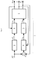
- FIG. 1 shows the state of the art according to the EP 0 259 382 B1 .
- the said logic modules need not be present as physical components, but can be realized as circuits in the control device of the internal combustion engine.
- FIG. 1 shows the state of the art according to the EP 0 259 382 B1 , Shown schematically is an internal combustion engine 1, the one
- Fuel gas mass flow u gas is supplied.
- the fuel gas mass flow u gas can be influenced via a regulator 5, which activates suitable actuators (for example port injection valves or gas metering device of a gas mixer).
- the in FIG. 1 The control loop shown above is the NOx emission control loop.
- the NOx emission control loop comprises in this case the modules or logical relationships with the reference numerals 2, 3, 4, 5 and the respective input and output variables. It contains in a suitable form (for example in the form of a look-up table or a function) the functional relationship 2 between boost pressure set point p d im (as output of functional relationship 2) and actual power Pg (as input of functional relationship 2) for a given NOx value in the form of a curve.
- the comparator 3 there is a desired-actual comparison between boost pressure setpoint p d im and actual boost pressure p im .
- the deviation p d im -p im is fed to a PID controller 4.
- the controller 5 can also be designed as a controller, ie without feedback of the target variable ⁇ d .
- the in FIG. 1 The control loop shown below is the power control loop. It includes another PID controller 6, the specific in a further comparator 7 deviation d P g as input - P g is fed between desired power P d g and actual power P g.
- the PID controller 6 outputs as output suitable, the Istladetik p in influencing control signals u p to those actuators (for example, compressor bypass valve or throttle valve), which on the one hand affect the Istladetik p im and on the other hand, the actual power P g resulting in the above-described strong coupling between the NOx emission control loop and the power control loop.
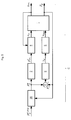
- FIG. 2 shows a first embodiment of the invention, wherein the same reference numerals denote the same components or logical operations as in FIG. 1 ,
- the boost pressure setpoint p d is supplied as input in a boost pressure regulator 8.
- This boost regulator 8 could be quite like in FIG. 1 shown in the form of a comparator 3 and a PID controller 4 be executed.
- an embodiment is preferred as a model-based controller, which in addition to the current actual boost pressure p in also the boost pressure setpoint p d im required as input.
- the output of the boost pressure regulator 8 takes place in the form of control signals u p , to those actuators (for example compressor bypass valve or throttle valve) which influence the actual boost pressure p im .
- These control signals u p were in FIG. 1 the output of the PID controller 6 and thus of the power control loop. Because in FIG. 2 these control signals u p are part of the NOx emission control loop, there is the strong coupling of FIG. 1 between NOx emission control loop and power control loop in the invention not.
- the power control loop of the FIG. 2 is different from that of the FIG. 1 only in that the controller 5, which the actuators (for example, port injection valves or gas metering a Gas mixer), which influence the fuel gas mass flow u gas , controls, is arranged in the power control loop.
- the controller 5 which the actuators (for example, port injection valves or gas metering a Gas mixer), which influence the fuel gas mass flow u gas , controls, is arranged in the power control loop.
- the controller 5 which the actuators (for example, port injection valves or gas metering a Gas mixer), which influence the fuel gas mass flow u gas , controls
- the controller 5 which the actuators (for example, port injection valves or gas metering a Gas mixer), which influence the fuel gas mass flow u gas , controls
- the controller 5 which the actuators (for example, port injection valves or gas metering a Gas mixer), which influence the fuel gas mass flow u gas , controls
- a model-based controller could also be provided.
- the functional relationship 2 results in the form described above as a simple curve.
- the functional relationship 2 can be corrected by including corrections with respect to the ignition timing, the inlet temperature, etc.
- FIG. 3 shows a second embodiment of the invention.
- a skip-fire control module 9 which as an input, the target power P d g is supplied.
- the output of the skip fire control module 9 takes place to the controller 5, which controls the fuel gas mass flow u gas so that no combustion occurs in selected cylinders of the internal combustion engine 1 for lack of fuel gas. This allows rapid adaptation to load changes. This is advantageous for port injection internal combustion engines.
- the FIG. 4 shows a third embodiment of the invention. In comparison to FIG.
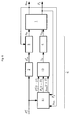
- FIG. 5 shows a fourth embodiment of the invention, wherein compared to FIG. 2 the functional relationship 2 is a Trajektoriengenerator 10 upstream.
- This converts a non-steady, step-shaped specification of the desired power P d, step g by a user in a continuous trajectory for the desired power P d g .
- a continuous function combining these values is selected, for example in the form of a (preferably linear) ramp or in the form of a polynomial or Like.
- the trajectory generator 10 can be supplied as input additionally the actual power P g .
- the deviation between the instantaneous value of the desired power P d g in accordance with the steady state function and the actual power P g can be monitored to such an extent that if the output power P d g is too high Deviation the continuous function of the target power P d g is limited to a certain value above the actual power Pg. This case may be relevant, for example, in a cold engine 1.
- FIG. 6 shows a fifth embodiment of the invention, in which compared to FIG. 2 a dead time compensation device 11 is provided. This is particularly advantageous for mixture-loaded internal combustion engines 1.
- Input of the dead time compensation device 11 are the target power P d g , the actual power P g and the actual boost pressure p im .
- the input signals P d g (t), P g (t), p are in (t) at time t in a (a dead time D time in the between an actual change in the fuel gas mass flow and the corresponding reaction of the internal combustion engine 1 -fit P g is) in the future t + D predicted P d form g (t + D), P g (t + D), p re-issued in the (t + D) as output.
- This output serves as input for a controller 12, which outputs a setpoint value for the lambda value ⁇ d as a function of the input.
- the prediction takes place in a manner known per se model-based by integration of those differential equations which describe the dynamic behavior of these variables. These differential equations are well known to those skilled in the art.
- FIG. 7 shows an embodiment of the invention, in which all measures of the aforementioned embodiments are provided together. Of course, here also individual measures could be omitted.
- the modules required for control / regulation and logical relationships are summarized for all embodiments.
- "controller” does not necessarily mean a physical component, but rather a specific function, which may be represented by a circuit, memory etc., for example.
Landscapes
- Engineering & Computer Science (AREA)
- Chemical & Material Sciences (AREA)
- Combustion & Propulsion (AREA)
- Mechanical Engineering (AREA)
- General Engineering & Computer Science (AREA)
- Computer Hardware Design (AREA)
- Microelectronics & Electronic Packaging (AREA)
- Electrical Control Of Air Or Fuel Supplied To Internal-Combustion Engine (AREA)
- Combined Controls Of Internal Combustion Engines (AREA)
- Output Control And Ontrol Of Special Type Engine (AREA)
Applications Claiming Priority (1)
| Application Number | Priority Date | Filing Date | Title |
|---|---|---|---|
| ATA575/2014A AT516134B1 (de) | 2014-07-22 | 2014-07-22 | Brennkraftmaschine mit einer Regeleinrichtung |
Publications (3)
| Publication Number | Publication Date |
|---|---|
| EP2977596A1 true EP2977596A1 (fr) | 2016-01-27 |
| EP2977596B1 EP2977596B1 (fr) | 2018-11-21 |
| EP2977596B8 EP2977596B8 (fr) | 2019-03-06 |
Family
ID=53761926
Family Applications (1)
| Application Number | Title | Priority Date | Filing Date |
|---|---|---|---|
| EP15002250.7A Active EP2977596B8 (fr) | 2014-07-22 | 2015-07-29 | Moteur a combustion interne dote d'un dispositif de reglage |
Country Status (7)
| Country | Link |
|---|---|
| US (1) | US10077729B2 (fr) |
| EP (1) | EP2977596B8 (fr) |
| JP (1) | JP6431825B2 (fr) |
| KR (2) | KR20160011596A (fr) |
| CN (1) | CN105275641B (fr) |
| AT (1) | AT516134B1 (fr) |
| BR (1) | BR102015016886B8 (fr) |
Cited By (7)
| Publication number | Priority date | Publication date | Assignee | Title |
|---|---|---|---|---|
| WO2020176911A1 (fr) | 2019-03-04 | 2020-09-10 | Innio Jenbacher Gmbh & Co Og | Moteur à combustion interne et procédé de fonctionnement d'un moteur à combustion interne |
| EP3726036A1 (fr) * | 2019-04-15 | 2020-10-21 | Winterthur Gas & Diesel AG | Procédé de fonctionnement d'un grand moteur ainsi que grand moteur |
| WO2024216308A1 (fr) | 2023-04-20 | 2024-10-24 | Innio Jenbacher Gmbh & Co Og | Moteur à combustion interne |
| WO2025010451A1 (fr) | 2023-07-11 | 2025-01-16 | Innio Jenbacher Gmbh & Co Og | Moteur à combustion interne et procédé de commande de celui-ci |
| WO2025147727A1 (fr) | 2024-01-12 | 2025-07-17 | Innio Jenbacher Gmbh & Co Og | Moteur à combustion interne |
| WO2026073295A1 (fr) | 2024-10-03 | 2026-04-09 | Innio Jenbacher Gmbh & Co Og | Moteur à combustion interne, et procédé et produit programme d'ordinateur pour son fonctionnement |
| US12612879B2 (en) | 2022-05-24 | 2026-04-28 | Innio Jenbacher Gmbh & Co Og | Method for operating an internal combustion engine |
Families Citing this family (6)
| Publication number | Priority date | Publication date | Assignee | Title |
|---|---|---|---|---|
| JP6296810B2 (ja) * | 2014-01-24 | 2018-03-20 | ヤンマー株式会社 | ガスエンジン |
| AT516320B1 (de) * | 2014-10-06 | 2016-07-15 | Ge Jenbacher Gmbh & Co Og | Verfahren zum Betreiben einer Selbstzündungs-Brennkraftmaschine |
| AT517216B1 (de) | 2015-06-30 | 2016-12-15 | Ge Jenbacher Gmbh & Co Og | Brennkraftmaschine mit einer Regeleinrichtung |
| US10718286B2 (en) * | 2016-08-23 | 2020-07-21 | Ford Global Technologies, Llc | System and method for controlling fuel supplied to an engine |
| CN108150315B (zh) * | 2017-12-29 | 2021-05-18 | 潍柴动力股份有限公司 | Egr排气处理装置及汽车 |
| CN111997771A (zh) * | 2020-08-27 | 2020-11-27 | 重庆潍柴发动机有限公司 | 一种多点喷射电控发动机的单缸功率自动修正方法 |
Citations (8)
| Publication number | Priority date | Publication date | Assignee | Title |
|---|---|---|---|---|
| EP0259382B1 (fr) | 1986-03-05 | 1989-10-04 | Jenbacher Werke AG | Dispositif de regulation de la proportion d'air de combustion au gaz |
| EP0687809A2 (fr) * | 1994-06-17 | 1995-12-20 | Hitachi, Ltd. | Dispositif et méthode de commande du couple de sortie d'un moteur à combustion interne |
| EP1158149A1 (fr) * | 2000-05-26 | 2001-11-28 | Jenbacher Aktiengesellschaft | Dispositif pour le calcul du rapport air-carburant dans un moteur à gaz |
| EP1225330A2 (fr) * | 2001-01-18 | 2002-07-24 | Jenbacher Aktiengesellschaft | Dispositif pour la régulation d'un moteur à allumage commandé |
| EP1602813A1 (fr) * | 2004-05-21 | 2005-12-07 | GE Jenbacher GmbH & Co. OHG | Procédé de régulation d'un moteur à combustion interne |
| US20080120009A1 (en) * | 2006-11-17 | 2008-05-22 | Michael Livshiz | Engine torque control at high pressure ratio |
| WO2012097389A2 (fr) * | 2011-01-18 | 2012-07-26 | Ge Jenbacher Gmbh & Co Ohg | Procédé pour faire fonctionner un moteur à combustion interne disposant d'au moins deux cylindres |
| EP2594443A1 (fr) * | 2011-11-17 | 2013-05-22 | IFP Energies nouvelles | Procédé de commande d'un système de propulsion hybride d'un véhicule en regime transitoire |
Family Cites Families (14)
| Publication number | Priority date | Publication date | Assignee | Title |
|---|---|---|---|---|
| DE19651238C2 (de) * | 1996-12-10 | 2001-06-21 | Bosch Gmbh Robert | Einrichtung Bestimmung des Zündwinkels einer Brennkraftmaschine |
| US5738070A (en) * | 1996-12-11 | 1998-04-14 | Caterpillar Inc. | Method and apparatus for operation of a speed-governed lean burn engine to improve load response |
| DE19808829B4 (de) | 1998-03-03 | 2006-04-13 | Man B & W Diesel Ag | Gasmotor |
| DE10116295A1 (de) | 2001-03-31 | 2002-10-10 | Nexans France S A | Vorrichtung zur Stromübertragung zwischen zwei Endstellen |
| JP4065784B2 (ja) * | 2001-04-03 | 2008-03-26 | 株式会社日立製作所 | 内燃機関の制御装置 |
| US6728625B2 (en) * | 2002-09-27 | 2004-04-27 | Caterpillar Inc | Humidity compensated charge density control for an internal combustion engine |
| US7932480B2 (en) | 2006-04-05 | 2011-04-26 | Mks Instruments, Inc. | Multiple heater control system with expandable modular functionality |
| JP4599390B2 (ja) | 2007-12-14 | 2010-12-15 | 三菱重工業株式会社 | マイクロパイロット噴射式ガスエンジン |
| US8146569B2 (en) * | 2009-05-12 | 2012-04-03 | GM Global Technology Operations LLC | Control systems and methods for newly assembled engines |
| US9122537B2 (en) | 2009-10-30 | 2015-09-01 | Cisco Technology, Inc. | Balancing server load according to availability of physical resources based on the detection of out-of-sequence packets |
| DE102010062198B4 (de) * | 2010-11-30 | 2015-08-20 | Mtu Onsite Energy Gmbh | Verfahren und Steuereinrichtung zum Betrieb eines Otto-Gasmotors |
| JP5803361B2 (ja) | 2011-07-12 | 2015-11-04 | いすゞ自動車株式会社 | アクチュエータの制御方法及びアクチュエータの制御装置 |
| JP5895570B2 (ja) | 2012-02-09 | 2016-03-30 | 株式会社デンソー | ガスエンジン制御システム |
| JP2013231428A (ja) | 2012-04-06 | 2013-11-14 | Nippon Soken Inc | 内燃機関の吸気システム |
-
2014
- 2014-07-22 AT ATA575/2014A patent/AT516134B1/de active
-
2015
- 2015-07-08 US US14/794,072 patent/US10077729B2/en active Active
- 2015-07-14 BR BR102015016886A patent/BR102015016886B8/pt active IP Right Grant
- 2015-07-17 JP JP2015142710A patent/JP6431825B2/ja active Active
- 2015-07-21 KR KR1020150103096A patent/KR20160011596A/ko not_active Ceased
- 2015-07-22 CN CN201510433951.2A patent/CN105275641B/zh active Active
- 2015-07-29 EP EP15002250.7A patent/EP2977596B8/fr active Active
-
2017
- 2017-10-27 KR KR1020170141346A patent/KR101910294B1/ko active Active
Patent Citations (8)
| Publication number | Priority date | Publication date | Assignee | Title |
|---|---|---|---|---|
| EP0259382B1 (fr) | 1986-03-05 | 1989-10-04 | Jenbacher Werke AG | Dispositif de regulation de la proportion d'air de combustion au gaz |
| EP0687809A2 (fr) * | 1994-06-17 | 1995-12-20 | Hitachi, Ltd. | Dispositif et méthode de commande du couple de sortie d'un moteur à combustion interne |
| EP1158149A1 (fr) * | 2000-05-26 | 2001-11-28 | Jenbacher Aktiengesellschaft | Dispositif pour le calcul du rapport air-carburant dans un moteur à gaz |
| EP1225330A2 (fr) * | 2001-01-18 | 2002-07-24 | Jenbacher Aktiengesellschaft | Dispositif pour la régulation d'un moteur à allumage commandé |
| EP1602813A1 (fr) * | 2004-05-21 | 2005-12-07 | GE Jenbacher GmbH & Co. OHG | Procédé de régulation d'un moteur à combustion interne |
| US20080120009A1 (en) * | 2006-11-17 | 2008-05-22 | Michael Livshiz | Engine torque control at high pressure ratio |
| WO2012097389A2 (fr) * | 2011-01-18 | 2012-07-26 | Ge Jenbacher Gmbh & Co Ohg | Procédé pour faire fonctionner un moteur à combustion interne disposant d'au moins deux cylindres |
| EP2594443A1 (fr) * | 2011-11-17 | 2013-05-22 | IFP Energies nouvelles | Procédé de commande d'un système de propulsion hybride d'un véhicule en regime transitoire |
Cited By (10)
| Publication number | Priority date | Publication date | Assignee | Title |
|---|---|---|---|---|
| WO2020176911A1 (fr) | 2019-03-04 | 2020-09-10 | Innio Jenbacher Gmbh & Co Og | Moteur à combustion interne et procédé de fonctionnement d'un moteur à combustion interne |
| US11566576B2 (en) | 2019-03-04 | 2023-01-31 | Innio Jenbacher Gmbh & Co Og | Internal combustion engine and method for operating an internal combustion engine |
| US11959431B2 (en) | 2019-03-04 | 2024-04-16 | Innio Jenbacher Gmbh & Co Og | Internal combustion engine and method for operating an internal combustion engine |
| EP3726036A1 (fr) * | 2019-04-15 | 2020-10-21 | Winterthur Gas & Diesel AG | Procédé de fonctionnement d'un grand moteur ainsi que grand moteur |
| CN111828181A (zh) * | 2019-04-15 | 2020-10-27 | 温特图尔汽柴油公司 | 用于操作大型发动机的方法和大型发动机 |
| US12612879B2 (en) | 2022-05-24 | 2026-04-28 | Innio Jenbacher Gmbh & Co Og | Method for operating an internal combustion engine |
| WO2024216308A1 (fr) | 2023-04-20 | 2024-10-24 | Innio Jenbacher Gmbh & Co Og | Moteur à combustion interne |
| WO2025010451A1 (fr) | 2023-07-11 | 2025-01-16 | Innio Jenbacher Gmbh & Co Og | Moteur à combustion interne et procédé de commande de celui-ci |
| WO2025147727A1 (fr) | 2024-01-12 | 2025-07-17 | Innio Jenbacher Gmbh & Co Og | Moteur à combustion interne |
| WO2026073295A1 (fr) | 2024-10-03 | 2026-04-09 | Innio Jenbacher Gmbh & Co Og | Moteur à combustion interne, et procédé et produit programme d'ordinateur pour son fonctionnement |
Also Published As
| Publication number | Publication date |
|---|---|
| CN105275641A (zh) | 2016-01-27 |
| KR20170123304A (ko) | 2017-11-07 |
| EP2977596B1 (fr) | 2018-11-21 |
| KR101910294B1 (ko) | 2018-10-19 |
| US20160025024A1 (en) | 2016-01-28 |
| BR102015016886B1 (pt) | 2022-05-17 |
| KR20160011596A (ko) | 2016-02-01 |
| AT516134A3 (de) | 2018-05-15 |
| JP6431825B2 (ja) | 2018-11-28 |
| AT516134B1 (de) | 2018-12-15 |
| US10077729B2 (en) | 2018-09-18 |
| JP2016023645A (ja) | 2016-02-08 |
| BR102015016886B8 (pt) | 2022-06-07 |
| CN105275641B (zh) | 2019-06-14 |
| BR102015016886A2 (pt) | 2016-06-28 |
| AT516134A2 (de) | 2016-02-15 |
| EP2977596B8 (fr) | 2019-03-06 |
Similar Documents
| Publication | Publication Date | Title |
|---|---|---|
| EP2977596B1 (fr) | Moteur a combustion interne dote d'un dispositif de reglage | |
| DE10329763B4 (de) | Koordinierte Regelung einer elektronischen Drosselklappe und eines Turboladers mit variabler Geometrie in ladedruckverstärkten und stöchiometrisch betriebenen Ottomotoren | |
| EP1592870B1 (fr) | Procede pour faire fonctionner un ensemble turbine a gaz | |
| DE69732884T2 (de) | Elektronisch steuerbares Abblaseventil | |
| DE102004056894A1 (de) | Verfahren und Vorrichtung zur Regelung des Ladedrucks einer Brennkraftmaschine | |
| AT511001B1 (de) | Verfahren zum betreiben einer über wenigstens zwei zylinder verfügenden brennkraftmaschine | |
| EP2990631B1 (fr) | Moteur à combustion interne et son procédé de fonctionnement | |
| EP3015688B1 (fr) | Procede destine au fonctionnement d'un moteur a combustion interne | |
| EP2732140B1 (fr) | Procédé de régulation d'un dispositif de récupération de chaleur pour un moteur à combustion interne | |
| DE102010043897B4 (de) | Verfahren und Vorrichtung zum Betreiben eines Verbrennungsmotors | |
| EP2910755A1 (fr) | Procédé destiné au fonctionnement d'un moteur à combustion interne | |
| DE102017116402B4 (de) | Verfahren und Vorrichtung zum Betreiben eines Gasmotors bei Betrieb mit niedriger Leistung, insbesondere in der Startphase | |
| DE60215903T2 (de) | Verfahren zur Steuerung eines Abgasturboladers mit verstellbarer Turbinengeometrie | |
| EP3317505B1 (fr) | Moteur à combustion interne muni d'un dispositif de régulation | |
| DE102010023636B4 (de) | Verfahren zum Betreiben eines Antriebsaggregats | |
| EP3317503B1 (fr) | Procédé de réglage d'un moteur | |
| EP0728922B1 (fr) | Régulation de débit de masse d'air avec constante d'intégration adaptée pour moteur à combustion interne turbocompressée | |
| EP3034851B1 (fr) | Moteur à combustion interne | |
| DE102015003013B4 (de) | Verfahren und Regelsystem zum Betreiben eines Motors | |
| DE102022202013A1 (de) | Verfahren zur Abgastemperaturregelung für ein verbrennungsmotorisch angetriebenes Kraftfahrzeug sowie Motorsteuerung eines Kraftfahrzeugs | |
| DE102005023260A1 (de) | Verfahren zur Regelung eines Abgasturboladers | |
| EP3071818B1 (fr) | Fonctionnement d'une installation de turbine à gaz comprenant un compresseur et une turbine | |
| DE102022133770B4 (de) | Verfahren zum Betreiben einer Brennkraftmaschine, Steuergerät für eine Brennkraftmaschine und Brennkraftmaschine mit einem solchen Steuergerät | |
| DE102015216099A1 (de) | Verfahren und Vorrichtung zum Betreiben eines Verbrennungsmotors mit Abgasrückführung | |
| EP1559890A2 (fr) | Méthode de commande d'un moteur à combustion interne avec turbocompresseur |
Legal Events
| Date | Code | Title | Description |
|---|---|---|---|
| PUAI | Public reference made under article 153(3) epc to a published international application that has entered the european phase |
Free format text: ORIGINAL CODE: 0009012 |
|
| AK | Designated contracting states |
Kind code of ref document: A1 Designated state(s): AL AT BE BG CH CY CZ DE DK EE ES FI FR GB GR HR HU IE IS IT LI LT LU LV MC MK MT NL NO PL PT RO RS SE SI SK SM TR |
|
| AX | Request for extension of the european patent |
Extension state: BA ME |
|
| 17P | Request for examination filed |
Effective date: 20160726 |
|
| RBV | Designated contracting states (corrected) |
Designated state(s): AL AT BE BG CH CY CZ DE DK EE ES FI FR GB GR HR HU IE IS IT LI LT LU LV MC MK MT NL NO PL PT RO RS SE SI SK SM TR |
|
| STAA | Information on the status of an ep patent application or granted ep patent |
Free format text: STATUS: EXAMINATION IS IN PROGRESS |
|
| 17Q | First examination report despatched |
Effective date: 20170317 |
|
| GRAP | Despatch of communication of intention to grant a patent |
Free format text: ORIGINAL CODE: EPIDOSNIGR1 |
|
| STAA | Information on the status of an ep patent application or granted ep patent |
Free format text: STATUS: GRANT OF PATENT IS INTENDED |
|
| INTG | Intention to grant announced |
Effective date: 20180625 |
|
| GRAS | Grant fee paid |
Free format text: ORIGINAL CODE: EPIDOSNIGR3 |
|
| GRAA | (expected) grant |
Free format text: ORIGINAL CODE: 0009210 |
|
| STAA | Information on the status of an ep patent application or granted ep patent |
Free format text: STATUS: THE PATENT HAS BEEN GRANTED |
|
| AK | Designated contracting states |
Kind code of ref document: B1 Designated state(s): AL AT BE BG CH CY CZ DE DK EE ES FI FR GB GR HR HU IE IS IT LI LT LU LV MC MK MT NL NO PL PT RO RS SE SI SK SM TR |
|
| REG | Reference to a national code |
Ref country code: CH Ref legal event code: EP |
|
| GRAT | Correction requested after decision to grant or after decision to maintain patent in amended form |
Free format text: ORIGINAL CODE: EPIDOSNCDEC |
|
| REG | Reference to a national code |
Ref country code: IE Ref legal event code: FG4D Free format text: LANGUAGE OF EP DOCUMENT: GERMAN |
|
| REG | Reference to a national code |
Ref country code: DE Ref legal event code: R096 Ref document number: 502015006892 Country of ref document: DE |
|
| REG | Reference to a national code |
Ref country code: AT Ref legal event code: REF Ref document number: 1067829 Country of ref document: AT Kind code of ref document: T Effective date: 20181215 |
|
| RAP2 | Party data changed (patent owner data changed or rights of a patent transferred) |
Owner name: GE JENBACHER GMBH & CO OG |
|
| REG | Reference to a national code |
Ref country code: CH Ref legal event code: PK Free format text: BERICHTIGUNG B8 |
|
| REG | Reference to a national code |
Ref country code: NL Ref legal event code: MP Effective date: 20181121 |
|
| RAP2 | Party data changed (patent owner data changed or rights of a patent transferred) |
Owner name: INNIO JENBACHER GMBH & CO OG |
|
| PG25 | Lapsed in a contracting state [announced via postgrant information from national office to epo] |
Ref country code: ES Free format text: LAPSE BECAUSE OF FAILURE TO SUBMIT A TRANSLATION OF THE DESCRIPTION OR TO PAY THE FEE WITHIN THE PRESCRIBED TIME-LIMIT Effective date: 20181121 Ref country code: LV Free format text: LAPSE BECAUSE OF FAILURE TO SUBMIT A TRANSLATION OF THE DESCRIPTION OR TO PAY THE FEE WITHIN THE PRESCRIBED TIME-LIMIT Effective date: 20181121 Ref country code: HR Free format text: LAPSE BECAUSE OF FAILURE TO SUBMIT A TRANSLATION OF THE DESCRIPTION OR TO PAY THE FEE WITHIN THE PRESCRIBED TIME-LIMIT Effective date: 20181121 Ref country code: BG Free format text: LAPSE BECAUSE OF FAILURE TO SUBMIT A TRANSLATION OF THE DESCRIPTION OR TO PAY THE FEE WITHIN THE PRESCRIBED TIME-LIMIT Effective date: 20190221 Ref country code: NO Free format text: LAPSE BECAUSE OF FAILURE TO SUBMIT A TRANSLATION OF THE DESCRIPTION OR TO PAY THE FEE WITHIN THE PRESCRIBED TIME-LIMIT Effective date: 20190221 Ref country code: LT Free format text: LAPSE BECAUSE OF FAILURE TO SUBMIT A TRANSLATION OF THE DESCRIPTION OR TO PAY THE FEE WITHIN THE PRESCRIBED TIME-LIMIT Effective date: 20181121 Ref country code: IS Free format text: LAPSE BECAUSE OF FAILURE TO SUBMIT A TRANSLATION OF THE DESCRIPTION OR TO PAY THE FEE WITHIN THE PRESCRIBED TIME-LIMIT Effective date: 20190321 Ref country code: FI Free format text: LAPSE BECAUSE OF FAILURE TO SUBMIT A TRANSLATION OF THE DESCRIPTION OR TO PAY THE FEE WITHIN THE PRESCRIBED TIME-LIMIT Effective date: 20181121 |
|
| PG25 | Lapsed in a contracting state [announced via postgrant information from national office to epo] |
Ref country code: SE Free format text: LAPSE BECAUSE OF FAILURE TO SUBMIT A TRANSLATION OF THE DESCRIPTION OR TO PAY THE FEE WITHIN THE PRESCRIBED TIME-LIMIT Effective date: 20181121 Ref country code: NL Free format text: LAPSE BECAUSE OF FAILURE TO SUBMIT A TRANSLATION OF THE DESCRIPTION OR TO PAY THE FEE WITHIN THE PRESCRIBED TIME-LIMIT Effective date: 20181121 Ref country code: AL Free format text: LAPSE BECAUSE OF FAILURE TO SUBMIT A TRANSLATION OF THE DESCRIPTION OR TO PAY THE FEE WITHIN THE PRESCRIBED TIME-LIMIT Effective date: 20181121 Ref country code: GR Free format text: LAPSE BECAUSE OF FAILURE TO SUBMIT A TRANSLATION OF THE DESCRIPTION OR TO PAY THE FEE WITHIN THE PRESCRIBED TIME-LIMIT Effective date: 20190222 Ref country code: RS Free format text: LAPSE BECAUSE OF FAILURE TO SUBMIT A TRANSLATION OF THE DESCRIPTION OR TO PAY THE FEE WITHIN THE PRESCRIBED TIME-LIMIT Effective date: 20181121 Ref country code: PT Free format text: LAPSE BECAUSE OF FAILURE TO SUBMIT A TRANSLATION OF THE DESCRIPTION OR TO PAY THE FEE WITHIN THE PRESCRIBED TIME-LIMIT Effective date: 20190321 |
|
| PG25 | Lapsed in a contracting state [announced via postgrant information from national office to epo] |
Ref country code: CZ Free format text: LAPSE BECAUSE OF FAILURE TO SUBMIT A TRANSLATION OF THE DESCRIPTION OR TO PAY THE FEE WITHIN THE PRESCRIBED TIME-LIMIT Effective date: 20181121 Ref country code: DK Free format text: LAPSE BECAUSE OF FAILURE TO SUBMIT A TRANSLATION OF THE DESCRIPTION OR TO PAY THE FEE WITHIN THE PRESCRIBED TIME-LIMIT Effective date: 20181121 Ref country code: PL Free format text: LAPSE BECAUSE OF FAILURE TO SUBMIT A TRANSLATION OF THE DESCRIPTION OR TO PAY THE FEE WITHIN THE PRESCRIBED TIME-LIMIT Effective date: 20181121 |
|
| REG | Reference to a national code |
Ref country code: DE Ref legal event code: R097 Ref document number: 502015006892 Country of ref document: DE |
|
| PG25 | Lapsed in a contracting state [announced via postgrant information from national office to epo] |
Ref country code: SK Free format text: LAPSE BECAUSE OF FAILURE TO SUBMIT A TRANSLATION OF THE DESCRIPTION OR TO PAY THE FEE WITHIN THE PRESCRIBED TIME-LIMIT Effective date: 20181121 Ref country code: RO Free format text: LAPSE BECAUSE OF FAILURE TO SUBMIT A TRANSLATION OF THE DESCRIPTION OR TO PAY THE FEE WITHIN THE PRESCRIBED TIME-LIMIT Effective date: 20181121 Ref country code: SM Free format text: LAPSE BECAUSE OF FAILURE TO SUBMIT A TRANSLATION OF THE DESCRIPTION OR TO PAY THE FEE WITHIN THE PRESCRIBED TIME-LIMIT Effective date: 20181121 Ref country code: EE Free format text: LAPSE BECAUSE OF FAILURE TO SUBMIT A TRANSLATION OF THE DESCRIPTION OR TO PAY THE FEE WITHIN THE PRESCRIBED TIME-LIMIT Effective date: 20181121 |
|
| PLBE | No opposition filed within time limit |
Free format text: ORIGINAL CODE: 0009261 |
|
| STAA | Information on the status of an ep patent application or granted ep patent |
Free format text: STATUS: NO OPPOSITION FILED WITHIN TIME LIMIT |
|
| 26N | No opposition filed |
Effective date: 20190822 |
|
| PG25 | Lapsed in a contracting state [announced via postgrant information from national office to epo] |
Ref country code: SI Free format text: LAPSE BECAUSE OF FAILURE TO SUBMIT A TRANSLATION OF THE DESCRIPTION OR TO PAY THE FEE WITHIN THE PRESCRIBED TIME-LIMIT Effective date: 20181121 |
|
| PG25 | Lapsed in a contracting state [announced via postgrant information from national office to epo] |
Ref country code: MC Free format text: LAPSE BECAUSE OF FAILURE TO SUBMIT A TRANSLATION OF THE DESCRIPTION OR TO PAY THE FEE WITHIN THE PRESCRIBED TIME-LIMIT Effective date: 20181121 |
|
| REG | Reference to a national code |
Ref country code: CH Ref legal event code: PL |
|
| PG25 | Lapsed in a contracting state [announced via postgrant information from national office to epo] |
Ref country code: TR Free format text: LAPSE BECAUSE OF FAILURE TO SUBMIT A TRANSLATION OF THE DESCRIPTION OR TO PAY THE FEE WITHIN THE PRESCRIBED TIME-LIMIT Effective date: 20181121 |
|
| REG | Reference to a national code |
Ref country code: BE Ref legal event code: MM Effective date: 20190731 |
|
| PG25 | Lapsed in a contracting state [announced via postgrant information from national office to epo] |
Ref country code: LI Free format text: LAPSE BECAUSE OF NON-PAYMENT OF DUE FEES Effective date: 20190731 Ref country code: CH Free format text: LAPSE BECAUSE OF NON-PAYMENT OF DUE FEES Effective date: 20190731 Ref country code: LU Free format text: LAPSE BECAUSE OF NON-PAYMENT OF DUE FEES Effective date: 20190729 Ref country code: BE Free format text: LAPSE BECAUSE OF NON-PAYMENT OF DUE FEES Effective date: 20190731 |
|
| PG25 | Lapsed in a contracting state [announced via postgrant information from national office to epo] |
Ref country code: IE Free format text: LAPSE BECAUSE OF NON-PAYMENT OF DUE FEES Effective date: 20190729 |
|
| PG25 | Lapsed in a contracting state [announced via postgrant information from national office to epo] |
Ref country code: CY Free format text: LAPSE BECAUSE OF FAILURE TO SUBMIT A TRANSLATION OF THE DESCRIPTION OR TO PAY THE FEE WITHIN THE PRESCRIBED TIME-LIMIT Effective date: 20181121 |
|
| PG25 | Lapsed in a contracting state [announced via postgrant information from national office to epo] |
Ref country code: MT Free format text: LAPSE BECAUSE OF FAILURE TO SUBMIT A TRANSLATION OF THE DESCRIPTION OR TO PAY THE FEE WITHIN THE PRESCRIBED TIME-LIMIT Effective date: 20181121 Ref country code: HU Free format text: LAPSE BECAUSE OF FAILURE TO SUBMIT A TRANSLATION OF THE DESCRIPTION OR TO PAY THE FEE WITHIN THE PRESCRIBED TIME-LIMIT; INVALID AB INITIO Effective date: 20150729 |
|
| REG | Reference to a national code |
Ref country code: AT Ref legal event code: MM01 Ref document number: 1067829 Country of ref document: AT Kind code of ref document: T Effective date: 20200729 |
|
| PG25 | Lapsed in a contracting state [announced via postgrant information from national office to epo] |
Ref country code: AT Free format text: LAPSE BECAUSE OF NON-PAYMENT OF DUE FEES Effective date: 20200729 |
|
| PG25 | Lapsed in a contracting state [announced via postgrant information from national office to epo] |
Ref country code: MK Free format text: LAPSE BECAUSE OF FAILURE TO SUBMIT A TRANSLATION OF THE DESCRIPTION OR TO PAY THE FEE WITHIN THE PRESCRIBED TIME-LIMIT Effective date: 20181121 |
|
| P01 | Opt-out of the competence of the unified patent court (upc) registered |
Effective date: 20230614 |
|
| PGFP | Annual fee paid to national office [announced via postgrant information from national office to epo] |
Ref country code: GB Payment date: 20250619 Year of fee payment: 11 |
|
| PGFP | Annual fee paid to national office [announced via postgrant information from national office to epo] |
Ref country code: FR Payment date: 20250620 Year of fee payment: 11 |
|
| PGFP | Annual fee paid to national office [announced via postgrant information from national office to epo] |
Ref country code: DE Payment date: 20250620 Year of fee payment: 11 |
|
| PGFP | Annual fee paid to national office [announced via postgrant information from national office to epo] |
Ref country code: IT Payment date: 20250619 Year of fee payment: 11 |