EP2977656A1 - Vanne a siege - Google Patents
Vanne a siege Download PDFInfo
- Publication number
- EP2977656A1 EP2977656A1 EP15177705.9A EP15177705A EP2977656A1 EP 2977656 A1 EP2977656 A1 EP 2977656A1 EP 15177705 A EP15177705 A EP 15177705A EP 2977656 A1 EP2977656 A1 EP 2977656A1
- Authority
- EP
- European Patent Office
- Prior art keywords
- region
- valve seat
- throttle
- throttle opening
- sealing
- Prior art date
- Legal status (The legal status is an assumption and is not a legal conclusion. Google has not performed a legal analysis and makes no representation as to the accuracy of the status listed.)
- Granted
Links
Images

Classifications
-
- F—MECHANICAL ENGINEERING; LIGHTING; HEATING; WEAPONS; BLASTING
- F16—ENGINEERING ELEMENTS AND UNITS; GENERAL MEASURES FOR PRODUCING AND MAINTAINING EFFECTIVE FUNCTIONING OF MACHINES OR INSTALLATIONS; THERMAL INSULATION IN GENERAL
- F16K—VALVES; TAPS; COCKS; ACTUATING-FLOATS; DEVICES FOR VENTING OR AERATING
- F16K1/00—Lift valves or globe valves, i.e. cut-off apparatus with closure members having at least a component of their opening and closing motion perpendicular to the closing faces
- F16K1/32—Details
- F16K1/34—Cutting-off parts, e.g. valve members, seats
- F16K1/42—Valve seats
-
- F—MECHANICAL ENGINEERING; LIGHTING; HEATING; WEAPONS; BLASTING
- F16—ENGINEERING ELEMENTS AND UNITS; GENERAL MEASURES FOR PRODUCING AND MAINTAINING EFFECTIVE FUNCTIONING OF MACHINES OR INSTALLATIONS; THERMAL INSULATION IN GENERAL
- F16K—VALVES; TAPS; COCKS; ACTUATING-FLOATS; DEVICES FOR VENTING OR AERATING
- F16K1/00—Lift valves or globe valves, i.e. cut-off apparatus with closure members having at least a component of their opening and closing motion perpendicular to the closing faces
- F16K1/32—Details
- F16K1/34—Cutting-off parts, e.g. valve members, seats
- F16K1/36—Valve members
-
- F—MECHANICAL ENGINEERING; LIGHTING; HEATING; WEAPONS; BLASTING
- F16—ENGINEERING ELEMENTS AND UNITS; GENERAL MEASURES FOR PRODUCING AND MAINTAINING EFFECTIVE FUNCTIONING OF MACHINES OR INSTALLATIONS; THERMAL INSULATION IN GENERAL
- F16K—VALVES; TAPS; COCKS; ACTUATING-FLOATS; DEVICES FOR VENTING OR AERATING
- F16K1/00—Lift valves or globe valves, i.e. cut-off apparatus with closure members having at least a component of their opening and closing motion perpendicular to the closing faces
- F16K1/32—Details
- F16K1/34—Cutting-off parts, e.g. valve members, seats
- F16K1/36—Valve members
- F16K1/38—Valve members of conical shape
-
- F—MECHANICAL ENGINEERING; LIGHTING; HEATING; WEAPONS; BLASTING
- F16—ENGINEERING ELEMENTS AND UNITS; GENERAL MEASURES FOR PRODUCING AND MAINTAINING EFFECTIVE FUNCTIONING OF MACHINES OR INSTALLATIONS; THERMAL INSULATION IN GENERAL
- F16K—VALVES; TAPS; COCKS; ACTUATING-FLOATS; DEVICES FOR VENTING OR AERATING
- F16K1/00—Lift valves or globe valves, i.e. cut-off apparatus with closure members having at least a component of their opening and closing motion perpendicular to the closing faces
- F16K1/32—Details
- F16K1/34—Cutting-off parts, e.g. valve members, seats
- F16K1/42—Valve seats
- F16K1/422—Valve seats attachable by a threaded connection to the housing
-
- F—MECHANICAL ENGINEERING; LIGHTING; HEATING; WEAPONS; BLASTING
- F16—ENGINEERING ELEMENTS AND UNITS; GENERAL MEASURES FOR PRODUCING AND MAINTAINING EFFECTIVE FUNCTIONING OF MACHINES OR INSTALLATIONS; THERMAL INSULATION IN GENERAL
- F16K—VALVES; TAPS; COCKS; ACTUATING-FLOATS; DEVICES FOR VENTING OR AERATING
- F16K25/00—Details relating to contact between valve members and seats
- F16K25/005—Particular materials for seats or closure elements
-
- F—MECHANICAL ENGINEERING; LIGHTING; HEATING; WEAPONS; BLASTING
- F16—ENGINEERING ELEMENTS AND UNITS; GENERAL MEASURES FOR PRODUCING AND MAINTAINING EFFECTIVE FUNCTIONING OF MACHINES OR INSTALLATIONS; THERMAL INSULATION IN GENERAL
- F16K—VALVES; TAPS; COCKS; ACTUATING-FLOATS; DEVICES FOR VENTING OR AERATING
- F16K47/00—Means in valves for absorbing fluid energy
- F16K47/04—Means in valves for absorbing fluid energy for decreasing pressure or noise level, the throttle being incorporated in the closure member
Definitions
- the invention relates to a control valve according to the specified in the preamble of claim 1. Art.
- the EP 2 547 936 B1 discloses a non-ceramic valve seat having a ceramic sleeve insert, wherein an actuator is provided which includes a closure member having a stopper area which is shut-offly cooperating with the valve seat and a ceramic throttle portion cooperating with the ceramic sleeve insert.
- the DE 31 48 521 A1 discloses a throttle valve in which a superhard coating is applied to stainless steel in the area of the throttle opening. This approach has the disadvantage that after wear of the layer, the valve must be replaced.
- a control armature for providing a fluid flow comprises a valve housing and an actuating element, which has a blocking region and a throttle region.
- the blocking region of the adjusting element may preferably be conical.
- the throttle region which is arranged in particular downstream of the blocking region in the direction of the valve seat, may be designed to taper starting from a cylindrical configuration.
- a valve seat is provided which has a sealing region and a throttle opening region, wherein the blocking region of the actuating element interacts with the sealing region of the valve seat in such a way that a blocking of the fluid flow is enabled, and the throttle region of the actuating element cooperates with the throttle opening region of the valve seat such that a Setting a defined fluid flow allows becomes.
- the sealing area may have a conical taper.
- the throttle opening region is formed in particular in the form of a hollow cylindrical element. Furthermore, the throttle opening area and the sealing area are at least superficially formed of the same hard material.
- valve seat is designed in the form of a valve seat insert, which has the throttle opening region and the sealing region, the valve seat insert being inserted into the valve housing.
- the valve seat insert can be used directly or indirectly in the valve housing.
- the hard material has a hardness of more than 65 HRc.
- the hard material may be ceramic, carbide or stellite. It can also consist of a hardened material.
- the valve seat insert may be integrally formed of solid material.
- the sealing edge which forms the sealing region with the blocking region, is larger in diameter than the diameter of the opening in the throttle opening region.
- the actuating element in the blocking region may have a material with a hardness which is at least 10 HRc (Rockwell) less than the hardness of the hard material of the valve seat insert. This increases the tightness of the valve, wherein preferably the soft sealing edge is not in the main flow area of the valve.
- valve seat insert may be integrally formed of a material.
- the hard material of the valve seat insert may be formed of ceramic, hard metal or stellite.
- the actuator may comprise a hardened material having a hardness greater than 70 HRc.
- the throttle opening area is also made of a material with a Hardness of more than 70 HRc is formed, ensuring an equal load of actuator in the throttle area and throttle opening area in the valve seat.
- the adjusting element may comprise two parts, wherein the adjusting element in the blocking region has a material having a hardness of less than 50 HRc and in the throttle region a hard metal, ceramic, stellite and / or a material having a hardness of more than 65 HRc having.
- a high wear resistance is achieved with ideal closure effect. Due to the softer blocking area, the risk of breakage of the hard and therefore brittle material due to high contact forces and impact loads can be significantly reduced. Due to the interchangeability of the valve seat insert and actuator, the period of use of the control valve can be significantly increased even if the valve seat insert is damaged.
- the throttle region of the actuating element and the valve seat insert made of ceramic is formed.
- the throttle region may have an idle stroke range and a control range, wherein in the idle stroke range, a change in the position of the actuating element relative to the throttle opening does not result in a significant change in the flow behavior, the idle stroke range being between the control range and the stop range.
- the throttle opening region and the sealing region are spaced apart from one another in the stroke direction.
- the blocking region can be spaced from the sealing region of the actuating element in accordance with the idle stroke region, before the fluid flow through the control region is finally released. This results in a lower pressure difference at the stopband and sealing area, whereby the wear in this area can be reduced.
- the throttle region and the blocking region of the actuating element are formed in two parts.
- the throttle region of ceramic and the blocking region are formed of a soft metal.
- an elastic element such as graphite or elastomer element may be arranged, which protects the ceramic parts from shocks and can also contribute to tolerance compensation.
- Such an elastic transition can also for the transition between the blocking area and the rest of the actuator, in particular the control rod be provided.
- the connection of the elastic transition of the connected element can be done by crimping, press-fitting, clamping, gluing, soldering
- valve seat insert can be inserted via an intermediate bush in the valve housing.
- the valve seat insert can in particular be pressed into the intermediate bush, glued in place, fixed by means of securing elements and / or elastically mounted in the axial direction.
- the intermediate bushing can be embodied in various configurations and, for example, fixed via an interference fit, by retaining rings or in the form of a screwed bushing via a screw thread in the valve housing.
- valve seat insert By executing an intermediate bush, a particularly good interchangeability of the valve seat insert is ensured in the valve housing.
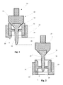
- Fig. 1 shows a schematic sectional view of a control valve 10 according to the invention in sealing operating condition.
- the control valve 10 includes a translationally adjustable actuator 12 which can cooperate with a valve seat insert 20.
- the actuating element comprises a blocking region 14 and a throttle region 16 for a controlling operation.
- the stopper portion 14 of the actuator 12 is formed of a soft metal having a Rockwell hardness of less than 50 HRc.
- the valve seat insert 20, which is made of ceramic, is inserted into the valve housing 22 shown schematically.
- the throttle area 16 comprises a no-lift area 24 and a control area 26. If the control element 12 is at its idle stroke area 24 at the level of the throttle opening 28, due to the design of the idle stroke area 24, the flow should be at any desired position of the control element within the lift position. Area 24 remains virtually unchanged. The flow is dependent on the flow cross section between the throttle opening 28 and the diameter of the control element in the idle stroke area 24.
- a deliberate modulation of the flow can take place as soon as the control region 26 is at the level of the throttle opening 28, as shown in FIG Fig. 2 is shown.
- Fig. 2 is the formed of ceramic throttle region 16 in the operating state for controlling the flow S shown.
- the idle stroke range 24 should be designed to be at least large enough that the cross section of the opening of the sealing region 18 is greater than the flow cross section in the idle stroke region 24 before the deliberate modulation of the flow in the control region 26 begins. Due to the spacing of the blocking region 14 from the sealing region 18 of the valve seat insert 20, wear of the blocking region 14, which is formed of softer metal, in contrast to the valve insert 20, can be prevented.
- the throttling region 16 exposed to the flow is likewise ceramic, in particular in its control region 26, as a result of which, owing to the hardness of the material, wear of the actuating element is effectively avoided.
- the valve seat insert 20 is formed in the throttle opening region 46 as well as in the sealing region 18 of ceramic material. This is used as an insert directly into the valve housing 22.
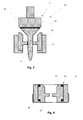
- Fig. 3 shows a sectional view of an actuating element 12 with a valve seat 20 which is incorporated in a valve housing 22.
- the embodiment according to Fig. 3 between the blocking region 14 and the remaining actuating element an elastic element 30.
- the locking portion 14 of the actuating element is also formed of ceramic.
- Fig. 4 shows a sectional view of a Einschraubbuchse 42 according to the invention, which has pressed a hard metal or ceramic valve seat insert 40, wherein the valve seat 40, the sealing portion 44 and the throttle opening portion 46 forms.
- a screw 42 provides a particularly advantageous design of an intermediate socket.
- the valve seat insert 40 is elastically supported by an elastic ring 48 opposite the screw bushing 42 and is connected by means of e.g. secured against falling out of a circlip.
- an elastic ring 48 opposite the screw bushing 42 and is connected by means of e.g. secured against falling out of a circlip.
- the actuator stops or high surface pressures can be collected, which significantly increases the durability of the brittle valve seat insert 40.
- the actuator also has a high hardness at its locking area, such a design of the screw 42 can significantly increase the life of the valve seat 90.
- the screw 42 can be screwed by means of a complementary thread in the valve housing.
- Fig. 5 shows a schematic view of a control armature 50.
- the control armature 50 includes a valve housing 52, an actuating element 54 which is coupled via an actuating rod 58 to an actuator 56.
- the actuator 54 cooperates with a valve seat insert inserted into the valve housing 52 60.
- the valve seat insert 60 inserted through an intermediate sleeve 62 in the valve housing 52.
- the adjusting element 54 is formed in two parts in this embodiment and has a throttle region 68 and a blocking region 70 in this embodiment.
- the stopper portion 70 is formed of a material softer than the valve seat insert 60 by at least 10 HRc.
Landscapes
- Engineering & Computer Science (AREA)
- General Engineering & Computer Science (AREA)
- Mechanical Engineering (AREA)
- Lift Valve (AREA)
Applications Claiming Priority (1)
| Application Number | Priority Date | Filing Date | Title |
|---|---|---|---|
| DE102014110246.0A DE102014110246A1 (de) | 2014-07-21 | 2014-07-21 | Stellarmatur |
Publications (2)
| Publication Number | Publication Date |
|---|---|
| EP2977656A1 true EP2977656A1 (fr) | 2016-01-27 |
| EP2977656B1 EP2977656B1 (fr) | 2017-09-13 |
Family
ID=53758043
Family Applications (1)
| Application Number | Title | Priority Date | Filing Date |
|---|---|---|---|
| EP15177705.9A Active EP2977656B1 (fr) | 2014-07-21 | 2015-07-21 | Vanne a siege |
Country Status (4)
| Country | Link |
|---|---|
| US (1) | US9689499B2 (fr) |
| EP (1) | EP2977656B1 (fr) |
| CN (1) | CN205047867U (fr) |
| DE (1) | DE102014110246A1 (fr) |
Cited By (1)
| Publication number | Priority date | Publication date | Assignee | Title |
|---|---|---|---|---|
| AT525340A1 (de) * | 2021-07-16 | 2023-02-15 | Boehlerit Gmbh & Co Kg | Ventil für eine Pumpe |
Families Citing this family (16)
| Publication number | Priority date | Publication date | Assignee | Title |
|---|---|---|---|---|
| US9544143B2 (en) | 2010-03-03 | 2017-01-10 | Duo Security, Inc. | System and method of notifying mobile devices to complete transactions |
| US9532222B2 (en) | 2010-03-03 | 2016-12-27 | Duo Security, Inc. | System and method of notifying mobile devices to complete transactions after additional agent verification |
| US9467463B2 (en) | 2011-09-02 | 2016-10-11 | Duo Security, Inc. | System and method for assessing vulnerability of a mobile device |
| ES2758755T3 (es) | 2015-06-01 | 2020-05-06 | Duo Security Inc | Método para aplicar normas de salud de punto final |
| US10344559B2 (en) * | 2016-05-26 | 2019-07-09 | Baker Hughes, A Ge Company, Llc | High temperature high pressure seal for downhole chemical injection applications |
| CN107061843B (zh) * | 2017-03-31 | 2019-12-03 | 江苏汉邦科技有限公司 | 一种应用于超临界流体色谱系统的自动背压阀 |
| DE102017119205A1 (de) * | 2017-08-22 | 2019-02-28 | Samson Ag | Stellventil |
| US10412113B2 (en) | 2017-12-08 | 2019-09-10 | Duo Security, Inc. | Systems and methods for intelligently configuring computer security |
| JP6435430B1 (ja) * | 2018-03-20 | 2018-12-05 | 株式会社テイエルブイ | 弁機構 |
| CA3097908A1 (fr) * | 2018-06-08 | 2019-12-12 | S.P.M. Flow Control, Inc. | Siege de soupape revetu, assemblage, et procedes de revetement d'un tel siege |
| US10851913B2 (en) | 2018-07-10 | 2020-12-01 | Caldera Engineering, Lc | Systems and methods for a plug head assembly |
| US11022228B2 (en) * | 2018-07-10 | 2021-06-01 | Caldera Engineering, Lc | Systems and methods for a plug valve |
| US11658962B2 (en) | 2018-12-07 | 2023-05-23 | Cisco Technology, Inc. | Systems and methods of push-based verification of a transaction |
| US11199268B2 (en) * | 2019-11-21 | 2021-12-14 | Ckd Corporation | Fluid control valve |
| DE102020112308A1 (de) * | 2020-05-06 | 2021-11-11 | Hammelmann GmbH | Druckregelventil |
| US12085175B2 (en) * | 2020-10-15 | 2024-09-10 | North Atlantic Imports, Llc | Valve structure for propane tank and method thereof |
Citations (9)
| Publication number | Priority date | Publication date | Assignee | Title |
|---|---|---|---|---|
| US2866477A (en) * | 1954-03-19 | 1958-12-30 | Crane Co | Combined throttle and stop valve |
| GB835367A (en) * | 1957-05-29 | 1960-05-18 | Siemens Ag | Improvements in or relating to forced-flow steam generators |
| US3521852A (en) * | 1966-12-12 | 1970-07-28 | Thomas S Gillis Jr | Throttle and shutoff valve |
| US4047695A (en) * | 1975-03-28 | 1977-09-13 | Chappell Industries, Inc. | Adjustable choke |
| DE3148521A1 (de) | 1980-12-15 | 1982-06-24 | Mitsui Coke Co. Ltd., Tokyo | "druckreduzierventil fuer kohleverfluessigungs- und -vergasungsanlagen" |
| BE1009354A6 (nl) * | 1995-05-04 | 1997-02-04 | Picanol Nv | Drukreduceerelement dat bestaat uit een elektrisch gestuurd smoorventiel. |
| WO2004092622A2 (fr) * | 2003-04-14 | 2004-10-28 | Swagelok Company | Siege de soupape a membrane |
| EP1757850A1 (fr) * | 2005-08-22 | 2007-02-28 | Dresser, Inc. | Vanne de régulation d'un fluide |
| US20110226980A1 (en) * | 2010-03-19 | 2011-09-22 | Richardson Jonathan W | Valves having ceramic trim with protected shut-off surfaces |
Family Cites Families (13)
| Publication number | Priority date | Publication date | Assignee | Title |
|---|---|---|---|---|
| US2706490A (en) * | 1950-01-18 | 1955-04-19 | Nordberg Manufacturing Co | Variable retraction valve |
| US3219311A (en) * | 1962-12-12 | 1965-11-23 | Chester A Siver | Valve assembly having particular head and seat cooperation |
| US3765448A (en) * | 1971-04-06 | 1973-10-16 | Chatham Precision Inc | Flow control valve |
| DE2457964A1 (de) * | 1974-12-07 | 1976-06-10 | Eckardt Ag J | Ventil, insbesondere stellventil |
| US4732364A (en) * | 1984-12-17 | 1988-03-22 | Ameron Iron Works USA, Inc. | Wear resistant diamond cladding |
| JPS62107216A (ja) * | 1985-11-05 | 1987-05-18 | Ngk Insulators Ltd | バルブシートインサート及びその製造法並びにそれを使用してなるシリンダーヘッド |
| US5350205A (en) * | 1993-05-20 | 1994-09-27 | Ewal Manufacturing Company, Inc. | High pressure gas fitting for repeated connection and disconnection |
| GB9405946D0 (en) * | 1994-03-25 | 1994-05-11 | Brico Eng | Sintered valve seat insert |
| US5718410A (en) * | 1995-01-27 | 1998-02-17 | Baumann; Hans D. | Small flow control valve with cartridge type seating arrangement |
| US7137612B2 (en) * | 2003-09-04 | 2006-11-21 | Whittaker Corporation | High recovery metering valve |
| US8051874B2 (en) * | 2006-09-13 | 2011-11-08 | Fisher Controls International Llc | Replaceable outlet liner for control valve |
| US9115814B2 (en) * | 2010-05-25 | 2015-08-25 | Emerson Process Management (Tianjin) Valve Co., Ltd. | Valve trim apparatus having a cavity to receive contaminates from a sealing surface |
| EP2853566B1 (fr) * | 2013-09-25 | 2017-07-26 | Crompton Technology Group Ltd. | Composites enrobés |
-
2014
- 2014-07-21 DE DE102014110246.0A patent/DE102014110246A1/de not_active Ceased
-
2015
- 2015-07-20 US US14/804,254 patent/US9689499B2/en active Active
- 2015-07-21 EP EP15177705.9A patent/EP2977656B1/fr active Active
- 2015-07-21 CN CN201520531464.5U patent/CN205047867U/zh not_active Expired - Lifetime
Patent Citations (10)
| Publication number | Priority date | Publication date | Assignee | Title |
|---|---|---|---|---|
| US2866477A (en) * | 1954-03-19 | 1958-12-30 | Crane Co | Combined throttle and stop valve |
| GB835367A (en) * | 1957-05-29 | 1960-05-18 | Siemens Ag | Improvements in or relating to forced-flow steam generators |
| US3521852A (en) * | 1966-12-12 | 1970-07-28 | Thomas S Gillis Jr | Throttle and shutoff valve |
| US4047695A (en) * | 1975-03-28 | 1977-09-13 | Chappell Industries, Inc. | Adjustable choke |
| DE3148521A1 (de) | 1980-12-15 | 1982-06-24 | Mitsui Coke Co. Ltd., Tokyo | "druckreduzierventil fuer kohleverfluessigungs- und -vergasungsanlagen" |
| BE1009354A6 (nl) * | 1995-05-04 | 1997-02-04 | Picanol Nv | Drukreduceerelement dat bestaat uit een elektrisch gestuurd smoorventiel. |
| WO2004092622A2 (fr) * | 2003-04-14 | 2004-10-28 | Swagelok Company | Siege de soupape a membrane |
| EP1757850A1 (fr) * | 2005-08-22 | 2007-02-28 | Dresser, Inc. | Vanne de régulation d'un fluide |
| US20110226980A1 (en) * | 2010-03-19 | 2011-09-22 | Richardson Jonathan W | Valves having ceramic trim with protected shut-off surfaces |
| EP2547936B1 (fr) | 2010-03-19 | 2014-01-15 | Fisher Controls International Llc | Organe interne d'une soupape avec des surfaces d'arrêt protegés |
Cited By (1)
| Publication number | Priority date | Publication date | Assignee | Title |
|---|---|---|---|---|
| AT525340A1 (de) * | 2021-07-16 | 2023-02-15 | Boehlerit Gmbh & Co Kg | Ventil für eine Pumpe |
Also Published As
| Publication number | Publication date |
|---|---|
| CN205047867U (zh) | 2016-02-24 |
| DE102014110246A1 (de) | 2016-01-21 |
| EP2977656B1 (fr) | 2017-09-13 |
| US9689499B2 (en) | 2017-06-27 |
| US20160018007A1 (en) | 2016-01-21 |
Similar Documents
| Publication | Publication Date | Title |
|---|---|---|
| EP2977656B1 (fr) | Vanne a siege | |
| EP1987278B1 (fr) | Soupape pre-asservie de limitation de la pression | |
| DE2430410A1 (de) | Ventil, insbesondere kugelventil | |
| DE102014223085B4 (de) | Dämpfventil für einen Schwingungsdämpfer | |
| EP3071853B1 (fr) | Ensemble piston-cylindre pour unité de débrayage, en particulier pour maître-cylindre d'un moyen d'actionnement d'embrayage hydraulique | |
| EP3280904B1 (fr) | Vanne de gaz | |
| DE102018102758A1 (de) | Feder für ein Rückschlagventil, Rückschlagventil mit einer derartigen Feder, regelbarer Schwingungsdämpfer mit einem solchen Rückschlagventil sowie Kraftfahrzeug mit einem derartigen regelbaren Schwingungsdämpfer | |
| DE102007016898A1 (de) | Ventil und Federeinrichtung hierfür | |
| EP2962022B1 (fr) | Soupape de trop-plein | |
| DE102019120225A1 (de) | Ventil und Vorrichtung zur Regelung von Drücken eines Strömungsmittels mit dem Ventil sowie Vorrichtung zur Sicherung des Ventils in dem Getriebebauteil | |
| EP1314921A2 (fr) | Vanne d'arret automatique | |
| DE102023112797A1 (de) | Druckregelventil zum Steuern oder Regeln eines Drucks eines Fluids in einem Pilotdruckraum und Schwingungsdämpfer mit einem solchen Druckregelventil | |
| EP1332283A1 (fr) | Aiguille d'injection presentant une pointe d'aiguille elastique | |
| DE102004018054B4 (de) | Dichtungsbalg | |
| EP3217050B1 (fr) | Dispositif d'étanchéité pour une vanne rotative | |
| EP3199852A1 (fr) | Vanne de régulation | |
| DE102014017549A1 (de) | Ventilanordnung | |
| DE102008027281A1 (de) | Regelventil | |
| DE102017118253B4 (de) | Dosierventil | |
| EP3999737A1 (fr) | Pompe à carburant à haute pression | |
| EP2952789A1 (fr) | Soupape de sécurité | |
| DE8801759U1 (de) | Federbelastetes Sperrventil | |
| DE20108618U1 (de) | Ventil, insbesondere Absteuer- oder Umgehungsventil für ein fluides Medium | |
| DE202011109263U1 (de) | Ventiloberteil | |
| DE102019120227A1 (de) | Ventil und Vorrichtung zur Regelung von Drücken eines Strömungsmittels mit dem Ventil sowie Vorrichtung zur Sicherung des Ventils in dem Getriebebauteil |
Legal Events
| Date | Code | Title | Description |
|---|---|---|---|
| PUAI | Public reference made under article 153(3) epc to a published international application that has entered the european phase |
Free format text: ORIGINAL CODE: 0009012 |
|
| AK | Designated contracting states |
Kind code of ref document: A1 Designated state(s): AL AT BE BG CH CY CZ DE DK EE ES FI FR GB GR HR HU IE IS IT LI LT LU LV MC MK MT NL NO PL PT RO RS SE SI SK SM TR |
|
| AX | Request for extension of the european patent |
Extension state: BA ME |
|
| 17P | Request for examination filed |
Effective date: 20160722 |
|
| RBV | Designated contracting states (corrected) |
Designated state(s): AL AT BE BG CH CY CZ DE DK EE ES FI FR GB GR HR HU IE IS IT LI LT LU LV MC MK MT NL NO PL PT RO RS SE SI SK SM TR |
|
| GRAP | Despatch of communication of intention to grant a patent |
Free format text: ORIGINAL CODE: EPIDOSNIGR1 |
|
| STAA | Information on the status of an ep patent application or granted ep patent |
Free format text: STATUS: GRANT OF PATENT IS INTENDED |
|
| INTG | Intention to grant announced |
Effective date: 20170330 |
|
| GRAS | Grant fee paid |
Free format text: ORIGINAL CODE: EPIDOSNIGR3 |
|
| GRAA | (expected) grant |
Free format text: ORIGINAL CODE: 0009210 |
|
| STAA | Information on the status of an ep patent application or granted ep patent |
Free format text: STATUS: THE PATENT HAS BEEN GRANTED |
|
| AK | Designated contracting states |
Kind code of ref document: B1 Designated state(s): AL AT BE BG CH CY CZ DE DK EE ES FI FR GB GR HR HU IE IS IT LI LT LU LV MC MK MT NL NO PL PT RO RS SE SI SK SM TR |
|
| REG | Reference to a national code |
Ref country code: GB Ref legal event code: FG4D Free format text: NOT ENGLISH |
|
| REG | Reference to a national code |
Ref country code: CH Ref legal event code: EP |
|
| REG | Reference to a national code |
Ref country code: IE Ref legal event code: FG4D Free format text: LANGUAGE OF EP DOCUMENT: GERMAN |
|
| REG | Reference to a national code |
Ref country code: AT Ref legal event code: REF Ref document number: 928491 Country of ref document: AT Kind code of ref document: T Effective date: 20171015 |
|
| REG | Reference to a national code |
Ref country code: DE Ref legal event code: R096 Ref document number: 502015001862 Country of ref document: DE |
|
| REG | Reference to a national code |
Ref country code: NL Ref legal event code: MP Effective date: 20170913 |
|
| REG | Reference to a national code |
Ref country code: LT Ref legal event code: MG4D |
|
| PG25 | Lapsed in a contracting state [announced via postgrant information from national office to epo] |
Ref country code: NO Free format text: LAPSE BECAUSE OF FAILURE TO SUBMIT A TRANSLATION OF THE DESCRIPTION OR TO PAY THE FEE WITHIN THE PRESCRIBED TIME-LIMIT Effective date: 20171213 Ref country code: FI Free format text: LAPSE BECAUSE OF FAILURE TO SUBMIT A TRANSLATION OF THE DESCRIPTION OR TO PAY THE FEE WITHIN THE PRESCRIBED TIME-LIMIT Effective date: 20170913 Ref country code: LT Free format text: LAPSE BECAUSE OF FAILURE TO SUBMIT A TRANSLATION OF THE DESCRIPTION OR TO PAY THE FEE WITHIN THE PRESCRIBED TIME-LIMIT Effective date: 20170913 Ref country code: HR Free format text: LAPSE BECAUSE OF FAILURE TO SUBMIT A TRANSLATION OF THE DESCRIPTION OR TO PAY THE FEE WITHIN THE PRESCRIBED TIME-LIMIT Effective date: 20170913 Ref country code: SE Free format text: LAPSE BECAUSE OF FAILURE TO SUBMIT A TRANSLATION OF THE DESCRIPTION OR TO PAY THE FEE WITHIN THE PRESCRIBED TIME-LIMIT Effective date: 20170913 |
|
| PG25 | Lapsed in a contracting state [announced via postgrant information from national office to epo] |
Ref country code: GR Free format text: LAPSE BECAUSE OF FAILURE TO SUBMIT A TRANSLATION OF THE DESCRIPTION OR TO PAY THE FEE WITHIN THE PRESCRIBED TIME-LIMIT Effective date: 20171214 Ref country code: ES Free format text: LAPSE BECAUSE OF FAILURE TO SUBMIT A TRANSLATION OF THE DESCRIPTION OR TO PAY THE FEE WITHIN THE PRESCRIBED TIME-LIMIT Effective date: 20170913 Ref country code: LV Free format text: LAPSE BECAUSE OF FAILURE TO SUBMIT A TRANSLATION OF THE DESCRIPTION OR TO PAY THE FEE WITHIN THE PRESCRIBED TIME-LIMIT Effective date: 20170913 Ref country code: BG Free format text: LAPSE BECAUSE OF FAILURE TO SUBMIT A TRANSLATION OF THE DESCRIPTION OR TO PAY THE FEE WITHIN THE PRESCRIBED TIME-LIMIT Effective date: 20171213 Ref country code: RS Free format text: LAPSE BECAUSE OF FAILURE TO SUBMIT A TRANSLATION OF THE DESCRIPTION OR TO PAY THE FEE WITHIN THE PRESCRIBED TIME-LIMIT Effective date: 20170913 |
|
| PG25 | Lapsed in a contracting state [announced via postgrant information from national office to epo] |
Ref country code: NL Free format text: LAPSE BECAUSE OF FAILURE TO SUBMIT A TRANSLATION OF THE DESCRIPTION OR TO PAY THE FEE WITHIN THE PRESCRIBED TIME-LIMIT Effective date: 20170913 |
|
| PG25 | Lapsed in a contracting state [announced via postgrant information from national office to epo] |
Ref country code: RO Free format text: LAPSE BECAUSE OF FAILURE TO SUBMIT A TRANSLATION OF THE DESCRIPTION OR TO PAY THE FEE WITHIN THE PRESCRIBED TIME-LIMIT Effective date: 20170913 Ref country code: PL Free format text: LAPSE BECAUSE OF FAILURE TO SUBMIT A TRANSLATION OF THE DESCRIPTION OR TO PAY THE FEE WITHIN THE PRESCRIBED TIME-LIMIT Effective date: 20170913 Ref country code: CZ Free format text: LAPSE BECAUSE OF FAILURE TO SUBMIT A TRANSLATION OF THE DESCRIPTION OR TO PAY THE FEE WITHIN THE PRESCRIBED TIME-LIMIT Effective date: 20170913 |
|
| PG25 | Lapsed in a contracting state [announced via postgrant information from national office to epo] |
Ref country code: IS Free format text: LAPSE BECAUSE OF FAILURE TO SUBMIT A TRANSLATION OF THE DESCRIPTION OR TO PAY THE FEE WITHIN THE PRESCRIBED TIME-LIMIT Effective date: 20180113 Ref country code: IT Free format text: LAPSE BECAUSE OF FAILURE TO SUBMIT A TRANSLATION OF THE DESCRIPTION OR TO PAY THE FEE WITHIN THE PRESCRIBED TIME-LIMIT Effective date: 20170913 Ref country code: EE Free format text: LAPSE BECAUSE OF FAILURE TO SUBMIT A TRANSLATION OF THE DESCRIPTION OR TO PAY THE FEE WITHIN THE PRESCRIBED TIME-LIMIT Effective date: 20170913 Ref country code: SM Free format text: LAPSE BECAUSE OF FAILURE TO SUBMIT A TRANSLATION OF THE DESCRIPTION OR TO PAY THE FEE WITHIN THE PRESCRIBED TIME-LIMIT Effective date: 20170913 Ref country code: SK Free format text: LAPSE BECAUSE OF FAILURE TO SUBMIT A TRANSLATION OF THE DESCRIPTION OR TO PAY THE FEE WITHIN THE PRESCRIBED TIME-LIMIT Effective date: 20170913 |
|
| REG | Reference to a national code |
Ref country code: DE Ref legal event code: R097 Ref document number: 502015001862 Country of ref document: DE |
|
| PLBE | No opposition filed within time limit |
Free format text: ORIGINAL CODE: 0009261 |
|
| STAA | Information on the status of an ep patent application or granted ep patent |
Free format text: STATUS: NO OPPOSITION FILED WITHIN TIME LIMIT |
|
| REG | Reference to a national code |
Ref country code: FR Ref legal event code: PLFP Year of fee payment: 4 |
|
| PG25 | Lapsed in a contracting state [announced via postgrant information from national office to epo] |
Ref country code: DK Free format text: LAPSE BECAUSE OF FAILURE TO SUBMIT A TRANSLATION OF THE DESCRIPTION OR TO PAY THE FEE WITHIN THE PRESCRIBED TIME-LIMIT Effective date: 20170913 |
|
| 26N | No opposition filed |
Effective date: 20180614 |
|
| PG25 | Lapsed in a contracting state [announced via postgrant information from national office to epo] |
Ref country code: MT Free format text: LAPSE BECAUSE OF FAILURE TO SUBMIT A TRANSLATION OF THE DESCRIPTION OR TO PAY THE FEE WITHIN THE PRESCRIBED TIME-LIMIT Effective date: 20170913 |
|
| PG25 | Lapsed in a contracting state [announced via postgrant information from national office to epo] |
Ref country code: SI Free format text: LAPSE BECAUSE OF FAILURE TO SUBMIT A TRANSLATION OF THE DESCRIPTION OR TO PAY THE FEE WITHIN THE PRESCRIBED TIME-LIMIT Effective date: 20170913 |
|
| REG | Reference to a national code |
Ref country code: CH Ref legal event code: PL |
|
| PG25 | Lapsed in a contracting state [announced via postgrant information from national office to epo] |
Ref country code: MC Free format text: LAPSE BECAUSE OF FAILURE TO SUBMIT A TRANSLATION OF THE DESCRIPTION OR TO PAY THE FEE WITHIN THE PRESCRIBED TIME-LIMIT Effective date: 20170913 Ref country code: LU Free format text: LAPSE BECAUSE OF NON-PAYMENT OF DUE FEES Effective date: 20180721 |
|
| REG | Reference to a national code |
Ref country code: BE Ref legal event code: MM Effective date: 20180731 |
|
| REG | Reference to a national code |
Ref country code: IE Ref legal event code: MM4A |
|
| PG25 | Lapsed in a contracting state [announced via postgrant information from national office to epo] |
Ref country code: IE Free format text: LAPSE BECAUSE OF NON-PAYMENT OF DUE FEES Effective date: 20180721 Ref country code: CH Free format text: LAPSE BECAUSE OF NON-PAYMENT OF DUE FEES Effective date: 20180731 Ref country code: LI Free format text: LAPSE BECAUSE OF NON-PAYMENT OF DUE FEES Effective date: 20180731 |
|
| PG25 | Lapsed in a contracting state [announced via postgrant information from national office to epo] |
Ref country code: BE Free format text: LAPSE BECAUSE OF NON-PAYMENT OF DUE FEES Effective date: 20180731 |
|
| PG25 | Lapsed in a contracting state [announced via postgrant information from national office to epo] |
Ref country code: TR Free format text: LAPSE BECAUSE OF FAILURE TO SUBMIT A TRANSLATION OF THE DESCRIPTION OR TO PAY THE FEE WITHIN THE PRESCRIBED TIME-LIMIT Effective date: 20170913 |
|
| PG25 | Lapsed in a contracting state [announced via postgrant information from national office to epo] |
Ref country code: PT Free format text: LAPSE BECAUSE OF FAILURE TO SUBMIT A TRANSLATION OF THE DESCRIPTION OR TO PAY THE FEE WITHIN THE PRESCRIBED TIME-LIMIT Effective date: 20170913 |
|
| PG25 | Lapsed in a contracting state [announced via postgrant information from national office to epo] |
Ref country code: MK Free format text: LAPSE BECAUSE OF NON-PAYMENT OF DUE FEES Effective date: 20170913 Ref country code: HU Free format text: LAPSE BECAUSE OF FAILURE TO SUBMIT A TRANSLATION OF THE DESCRIPTION OR TO PAY THE FEE WITHIN THE PRESCRIBED TIME-LIMIT; INVALID AB INITIO Effective date: 20150721 Ref country code: CY Free format text: LAPSE BECAUSE OF FAILURE TO SUBMIT A TRANSLATION OF THE DESCRIPTION OR TO PAY THE FEE WITHIN THE PRESCRIBED TIME-LIMIT Effective date: 20170913 |
|
| PG25 | Lapsed in a contracting state [announced via postgrant information from national office to epo] |
Ref country code: AL Free format text: LAPSE BECAUSE OF FAILURE TO SUBMIT A TRANSLATION OF THE DESCRIPTION OR TO PAY THE FEE WITHIN THE PRESCRIBED TIME-LIMIT Effective date: 20170913 |
|
| REG | Reference to a national code |
Ref country code: AT Ref legal event code: MM01 Ref document number: 928491 Country of ref document: AT Kind code of ref document: T Effective date: 20200721 |
|
| PG25 | Lapsed in a contracting state [announced via postgrant information from national office to epo] |
Ref country code: AT Free format text: LAPSE BECAUSE OF NON-PAYMENT OF DUE FEES Effective date: 20200721 |
|
| P01 | Opt-out of the competence of the unified patent court (upc) registered |
Effective date: 20230713 |
|
| PGFP | Annual fee paid to national office [announced via postgrant information from national office to epo] |
Ref country code: DE Payment date: 20250722 Year of fee payment: 11 |
|
| PGFP | Annual fee paid to national office [announced via postgrant information from national office to epo] |
Ref country code: GB Payment date: 20250722 Year of fee payment: 11 |
|
| PGFP | Annual fee paid to national office [announced via postgrant information from national office to epo] |
Ref country code: FR Payment date: 20250725 Year of fee payment: 11 |