EP2977657B1 - Structure de robinet à température d'eau constante - Google Patents
Structure de robinet à température d'eau constante Download PDFInfo
- Publication number
- EP2977657B1 EP2977657B1 EP15175961.0A EP15175961A EP2977657B1 EP 2977657 B1 EP2977657 B1 EP 2977657B1 EP 15175961 A EP15175961 A EP 15175961A EP 2977657 B1 EP2977657 B1 EP 2977657B1
- Authority
- EP
- European Patent Office
- Prior art keywords
- water
- output
- hole
- hot
- constant
- Prior art date
- Legal status (The legal status is an assumption and is not a legal conclusion. Google has not performed a legal analysis and makes no representation as to the accuracy of the status listed.)
- Not-in-force
Links
- XLYOFNOQVPJJNP-UHFFFAOYSA-N water Substances O XLYOFNOQVPJJNP-UHFFFAOYSA-N 0.000 title claims description 144
- 230000006835 compression Effects 0.000 claims description 6
- 238000007906 compression Methods 0.000 claims description 6
- 238000010276 construction Methods 0.000 description 3
- 238000009434 installation Methods 0.000 description 2
- 230000009467 reduction Effects 0.000 description 2
- 230000001105 regulatory effect Effects 0.000 description 2
- 239000000919 ceramic Substances 0.000 description 1
- 230000006872 improvement Effects 0.000 description 1
- 238000012986 modification Methods 0.000 description 1
- 230000004048 modification Effects 0.000 description 1
Images


Classifications
-
- F—MECHANICAL ENGINEERING; LIGHTING; HEATING; WEAPONS; BLASTING
- F16—ENGINEERING ELEMENTS AND UNITS; GENERAL MEASURES FOR PRODUCING AND MAINTAINING EFFECTIVE FUNCTIONING OF MACHINES OR INSTALLATIONS; THERMAL INSULATION IN GENERAL
- F16K—VALVES; TAPS; COCKS; ACTUATING-FLOATS; DEVICES FOR VENTING OR AERATING
- F16K19/00—Arrangements of valves and flow lines specially adapted for mixing fluids
- F16K19/006—Specially adapted for faucets
-
- F—MECHANICAL ENGINEERING; LIGHTING; HEATING; WEAPONS; BLASTING
- F16—ENGINEERING ELEMENTS AND UNITS; GENERAL MEASURES FOR PRODUCING AND MAINTAINING EFFECTIVE FUNCTIONING OF MACHINES OR INSTALLATIONS; THERMAL INSULATION IN GENERAL
- F16K—VALVES; TAPS; COCKS; ACTUATING-FLOATS; DEVICES FOR VENTING OR AERATING
- F16K31/00—Actuating devices; Operating means; Releasing devices
- F16K31/002—Actuating devices; Operating means; Releasing devices actuated by temperature variation
-
- G—PHYSICS
- G05—CONTROLLING; REGULATING
- G05D—SYSTEMS FOR CONTROLLING OR REGULATING NON-ELECTRIC VARIABLES
- G05D23/00—Control of temperature
- G05D23/01—Control of temperature without auxiliary power
- G05D23/13—Control of temperature without auxiliary power by varying the mixing ratio of two fluids having different temperatures
- G05D23/1306—Control of temperature without auxiliary power by varying the mixing ratio of two fluids having different temperatures for liquids
- G05D23/132—Control of temperature without auxiliary power by varying the mixing ratio of two fluids having different temperatures for liquids with temperature sensing element
- G05D23/134—Control of temperature without auxiliary power by varying the mixing ratio of two fluids having different temperatures for liquids with temperature sensing element measuring the temperature of mixed fluid
- G05D23/1346—Control of temperature without auxiliary power by varying the mixing ratio of two fluids having different temperatures for liquids with temperature sensing element measuring the temperature of mixed fluid with manual temperature setting means
- G05D23/1353—Control of temperature without auxiliary power by varying the mixing ratio of two fluids having different temperatures for liquids with temperature sensing element measuring the temperature of mixed fluid with manual temperature setting means combined with flow controlling means
Definitions
- the present invention relates to a faucet structure, and in particular to a constant water temperature faucet structure.
- the constant water temperature faucet structure is also referred to as constant temperature water faucet, or constant temperature shower water mixing faucet. Its function is to mix the hot and cold water automatically into warm water of preset temperature.
- the hot and cold water mixing faucet is referred to as a Two Handle Mixer.
- a user has to rotate the hot water and cold water rotation knobs, to control and regulate the input amount of hot water and cold water, to mix them into warm water of a desired temperature.
- the second generation hot-cold water mixing faucet is referred to as a Single Handle Faucet, having its center provided with a temperature adjusting valve core of ceramic plate.
- the user may swing the handle to the left or to the right, to adjust the temperature of the mixed water; or the user may swing the handle upward or downward, to adjust the amount of the output water.
- Different designs of conventional water mixing faucets are known, for example, from the documents US 5 779 139 A , DE 42 06 703 A1 and CN 102 221 100 A including a main body, a cold water input tube and a hot water input tube.
- the present invention provides a constant water temperature faucet structure, to overcome the shortcomings of the prior art.
- a major objective of the present invention is to provide a constant water temperature faucet structure, that is capable of regulating the temperature of output water at fast speed, reducing the length of water channel, while saving the space occupied by the faucet.
- the constant water temperature faucet structure of the present invention includes: a main body, a cold water input tube, a hot water input tube, an output water switching handle, and a temperature control rotation handle.
- the main body includes: an outer shell, a constant temperature valve core, a water channel switching rod, a central hole channel, a compression spring, a tight seal pad, a water outlet hole, and a water output hole.
- the cold water input tube and the hot water input tube are connected respectively to the outer shell, inside the outer shell is provided with a constant temperature valve core connected to the cold water input tube and the hot water input tube, and the water channel switching rod in communication with a water output port of the constant temperature valve core.
- a central hole channel In the central portion of the water channel switching rod is provided with a central hole channel.
- On the surface of the water channel switching rod is provided with a water outlet hole in communication with the central hole channel.
- On the outer shell is provided with the water output hole in communication with the water outlet hole, while on the water outlet hole is provided with a tight seal pad, having its center provided with a water passage hole.
- a compression spring is provided between the tight seal pad and the water outlet hole, and the constant temperature valve core is connected to the temperature control rotation handle located at one end of the outer shell, while the output water switching handle located at the other end of the outer shell is connected to the water channel switching rod.
- the axial line of the water output hole is perpendicular to the plane of axial lines of the hot and cold water input tubes.
- the two water output holes on the outer shell are disposed symmetrically on the two sides of the plane of axial lines of the hot and cold water input tubes.
- the water channel switching rod is designed to have three working positions: one water-close working position, and two water-output working positions.
- the axial line of the water outlet hole is in the plane of axial lines of the hot and cold water input tubes.
- the axial line of the water outlet hole is perpendicular to the plane of axial lines of the hot and cold water input tubes. At this time, the water outlet hole is in communication with the water output hole.
- the present invention has the following advantages: simple in construction and convenient in installation, to achieve cost reduction; water temperature can be adjusted at high speed, to reduce length of water channel, and save the space occupied by the faucet.
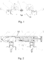
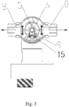
- Figs. 1 to 6 respectively for a perspective view of a constant water temperature faucet structure according to an embodiment of the present invention; a cross section view of a constant water temperature faucet structure according to an embodiment of the present invention; a cross section view of a constant water temperature faucet structure along an A-A line of Fig. 2 according to an embodiment of the present invention; a partially exploded view of a constant water temperature faucet structure of Fig. 1 according to an embodiment of the present invention; another partially exploded view of a constant water temperature faucet structure of Fig. 1 according to an embodiment of the present invention; and an exploded view of an output water switching handle according to an embodiment of the present invention.
- the constant water temperature faucet structure includes: a main body 14, a cold water input tube 1, a hot water input tube 2, an output water switching handle 11, and a temperature control rotation handle 10.
- the main body 14 includes: an outer shell 3, a constant temperature valve core 4, a water channel switching rod 5, a central hole channel 6, a water outlet hole 7, a compression spring 15, a tight seal pad 9, and a water output hole 8.
- the cold water input tube 1 and the hot water input tube 2 are connected respectively to the outer shell 3, inside the outer shell 3 is provided with the constant temperature valve core 4 connected to the cold water input tube 1 and the hot water input tube 2, and the water channel switching rod 5 in communication with a water output port of the constant temperature valve core 4.
- the central portion of the water channel switching rod 5 is provided with a central hole channel 6.
- On the surface of the water channel switching rod 5 is provided with a water outlet hole 7 in communication with the central hole channel 6.
- On the outer shell 3 is provided with the water output hole 8 in communication with the water outlet hole 7, on the water outlet hole 7 is provided with a tight seal pad 9, having its center provided with a water passage hole.
- a compression spring 15 is provided between the tight seal pad 9 and the water outlet hole 7, and the constant temperature valve core 4 is connected to the temperature control rotation handle 10 located at one end of the outer shell 3, while the output water switching handle 11 located at the other end of the outer shell 3 is connected to the water channel switching rod 5.
- the axial line of the water output hole 8 is perpendicular to the plane of axial lines of the cold and hot water input tubes 1 and 2.
- the two water output holes 8 on the outer shell 3 are disposed symmetrically on the two sides of the plane of axial lines of the cold and hot water input tubes 1 and 2.
- the water channel switching rod 5 is designed to have three working positions: one water-close working position, and two water-output working positions.
- the axial line of the water outlet hole 7 is in the plane of axial lines of the cold and hot water input tubes 1 and 2.
- the axial line of the water outlet hole 7 is perpendicular to the plane of axial lines of the cold and hot water input tubes 1 and 2. At this time, the water outlet hole 7 is in communication with the water output hole 8.
- the rear end cross section of the water channel switching rod 5 is of a cross shape, while the output water switching handle 11 is a circular sleeve. At the bottom of the circular sleeve is provided with a protrusion column. On the protrusion column is provided with an open slot 12 matching and working in cooperation with the rear end cross shape cross section of the water channel switching rod 5.
- the present invention has the following advantages: simple in construction and convenient in installation, to achieve cost reduction; water temperature can be adjusted at high speed, to reduce length of water channel, and save the space occupied by the faucet.
Landscapes
- Engineering & Computer Science (AREA)
- General Engineering & Computer Science (AREA)
- Mechanical Engineering (AREA)
- Physics & Mathematics (AREA)
- General Physics & Mathematics (AREA)
- Automation & Control Theory (AREA)
- Multiple-Way Valves (AREA)
- Domestic Plumbing Installations (AREA)
Claims (3)
- Structure de robinet à température d'eau constante, comprenant: un corps principal (14), un tube d'entrée d'eau froide (1), un tube d'entrée d'eau chaude (2), une poignée de permutation d'eau débitée (11), et une poignée de rotation de commande de température (10), dans laquelle le corps principal (14) possède une enveloppe extérieure (3) qui reçoit un noyau de valve à température constante (4), une tige de permutation de canal d'eau (5) et un canal à trou central (6), dans laquelle le tube d'entrée d'eau froide (1) et le tube d'entrée d'eau chaude (2) sont raccordés respectivement à l'enveloppe extérieure (3), dans laquelle le noyau de valve à température constante (4) prévu à l'intérieur de l'enveloppe extérieure (3) est raccordé au tube d'entrée d'eau froide (1) et au tube d'entrée d'eau chaude (2), et dans laquelle la tige de permutation de canal d'eau (5) est en communication avec un orifice de débit d'eau du noyau de valve à température constante (4), dans laquelle le canal à trou central (6) est prévu dans une portion centrale de la tige de permutation de canal d'eau (5), et dans laquelle un trou de sortie d'eau (7) est formé sur une surface de la tige de permutation de canal d'eau (5), dans laquelle le trou de sortie d'eau (7) communique avec le canal à trou central (6), dans laquelle, sur l'enveloppe extérieure (3), un trou de débit d'eau (8) est prévu qui communique avec le trou de sortie d'eau (7), et dans laquelle le noyau de valve à température constante (4) est raccordé à la poignée de rotation de commande de température (10) située à une extrémité de l'enveloppe extérieure (3), alors que la poignée de permutation d'eau débitée (11) située à l'autre extrémité de l'enveloppe extérieure (3) est raccordée à la tige de permutation de canal d'eau (5),
caractérisée en ce que la structure de robinet à température d'eau constante comprend en outre:un ressort de compression (15), etune pièce de joint d'étanchéité (9),dans laquelle la pièce de joint d'étanchéité (9) est disposée sur le trou de sortie d'eau (7) et a son centre pourvu d'un trou de passage d'eau, et dans laquelle le ressort de compression (15) est prévu entre la pièce de joint d'étanchéité (9) et le trou de sortie d'eau (7). - Structure de robinet à température d'eau constante selon la revendication 1, dans laquelle une ligne axiale du trou de débit d'eau (8) est perpendiculaire à un plan des lignes axiales des tubes d'entrée d'eaux chaude et froide (1, 2), et dans laquelle les deux trous de débit d'eau (8) sur l'enveloppe extérieure (3) sont disposés symétriquement sur deux côtés du plan des lignes axiales des tubes d'entrée d'eaux chaude et froide (1, 2).
- Structure de robinet à température d'eau constante selon la revendication 2, dans laquelle la tige de permutation de canal d'eau (5) possède trois positions de fonctionnement: une position de fonctionnement de fermeture d'eau et deux positions de fonctionnement de débit d'eau,
dans laquelle, lorsque la tige de permutation de canal d'eau (5) est dans la position de fonctionnement de fermeture d'eau, la ligne axiale du trou de sortie d'eau (7) est dans le plan des lignes axiales des tubes d'entrée d'eaux chaude et froide (1, 2), et
lorsque la tige de permutation de canal d'eau (5) est dans la position de fonctionnement de débit d'eau, la ligne axiale du trou de sortie d'eau (7) est perpendiculaire au plan des lignes axiales des tubes d'entrée d'eaux chaude et froide (1, 2), de telle sorte que le trou de sortie d'eau (7) soit en communication avec le trou de débit d'eau (8).
Applications Claiming Priority (1)
| Application Number | Priority Date | Filing Date | Title |
|---|---|---|---|
| CN201420405292.2U CN204083355U (zh) | 2014-07-22 | 2014-07-22 | 便捷恒温龙头结构 |
Publications (2)
| Publication Number | Publication Date |
|---|---|
| EP2977657A1 EP2977657A1 (fr) | 2016-01-27 |
| EP2977657B1 true EP2977657B1 (fr) | 2018-04-18 |
Family
ID=52176076
Family Applications (1)
| Application Number | Title | Priority Date | Filing Date |
|---|---|---|---|
| EP15175961.0A Not-in-force EP2977657B1 (fr) | 2014-07-22 | 2015-07-08 | Structure de robinet à température d'eau constante |
Country Status (2)
| Country | Link |
|---|---|
| EP (1) | EP2977657B1 (fr) |
| CN (1) | CN204083355U (fr) |
Families Citing this family (8)
| Publication number | Priority date | Publication date | Assignee | Title |
|---|---|---|---|---|
| KR101855681B1 (ko) * | 2016-05-13 | 2018-05-08 | 블라디미르 이 | 냉·온수 미세조절용 수전 |
| CN107781466A (zh) * | 2016-08-30 | 2018-03-09 | 厦门松霖科技股份有限公司 | 模块化温控和切换控制的淋浴龙头机构 |
| CN106122518A (zh) * | 2016-08-31 | 2016-11-16 | 开平市怀特阀芯有限公司 | 一种恒温水龙头 |
| CN109654289B (zh) * | 2017-10-12 | 2024-10-15 | 厦门松霖科技股份有限公司 | 低压大流量淋浴器 |
| FR3072752B1 (fr) * | 2017-10-24 | 2020-01-17 | Vernet | Ensemble interne pour un mitigeur |
| GB2571560B (en) * | 2018-03-01 | 2020-06-03 | Kohler Mira Ltd | Bar valve |
| CN112576787A (zh) * | 2019-09-29 | 2021-03-30 | 路达(厦门)工业有限公司 | 置物防烫恒温龙头 |
| CN213271136U (zh) * | 2020-07-30 | 2021-05-25 | 福建西河卫浴科技有限公司 | 一种分水器 |
Family Cites Families (3)
| Publication number | Priority date | Publication date | Assignee | Title |
|---|---|---|---|---|
| DE4206703A1 (de) * | 1992-03-04 | 1993-09-09 | Grohe Armaturen Friedrich | Mischbatterie |
| JP2838265B2 (ja) * | 1995-12-20 | 1998-12-16 | エヌテーシー工業株式会社 | 自動混合水栓 |
| CN102221100B (zh) * | 2011-06-07 | 2014-07-30 | 浙江苏泊尔卫浴有限公司 | 一种隔热水龙头 |
-
2014
- 2014-07-22 CN CN201420405292.2U patent/CN204083355U/zh not_active Expired - Fee Related
-
2015
- 2015-07-08 EP EP15175961.0A patent/EP2977657B1/fr not_active Not-in-force
Non-Patent Citations (1)
| Title |
|---|
| None * |
Also Published As
| Publication number | Publication date |
|---|---|
| CN204083355U (zh) | 2015-01-07 |
| EP2977657A1 (fr) | 2016-01-27 |
Similar Documents
| Publication | Publication Date | Title |
|---|---|---|
| EP2977657A1 (fr) | Structure de robinet à température d'eau constante | |
| EP3377792B1 (fr) | Régulateur d'écoulement réglable | |
| EP2664830B1 (fr) | Robinets thermostatiques de double commande à manche unique | |
| US20170002552A1 (en) | Water purifying faucet not having pull-out function | |
| CN204164426U (zh) | 一种单柄双控恒温阀 | |
| EP2410218B1 (fr) | Améliorations pour les mitigeurs à commande unique pour eau froide et eau chaude | |
| EP2988039B1 (fr) | Robinet de thermostat | |
| EP2789885A1 (fr) | Mélangeur thermostatique externe, en particulier pour des éléments hygiéno-sanitaires, avec une sécurité élevée contre le risque de brûlures de contact | |
| CN104265951A (zh) | 单柄双控恒温阀 | |
| US20200208384A1 (en) | Press switch shower faucet | |
| CN206419508U (zh) | 一种浴缸水龙头 | |
| CN103375610B (zh) | 用于调节冷热水及出水量的混水阀 | |
| CN205315776U (zh) | 双控恒温阀 | |
| CN108903650B (zh) | 一种可调温出水装置及饮水机 | |
| CN211202980U (zh) | 一种使用方便的恒温淋浴龙头 | |
| JP2006329334A (ja) | 湯水混合栓 | |
| CN223318511U (zh) | 一种混合阀及水龙头 | |
| CN206682357U (zh) | 一种多功能控水阀 | |
| US2870787A (en) | Warm and cold water mixing valve for baths, sinks and the like | |
| CN207921384U (zh) | 多功能阀 | |
| CN205745458U (zh) | 一种精密淋浴龙头 | |
| CN206320352U (zh) | 一种双联面盆龙头 | |
| CN218091085U (zh) | 一种入墙式龙头 | |
| CN206487908U (zh) | 一种防烫水龙头 | |
| CN113404900B (zh) | 一种调温水龙头 |
Legal Events
| Date | Code | Title | Description |
|---|---|---|---|
| PUAI | Public reference made under article 153(3) epc to a published international application that has entered the european phase |
Free format text: ORIGINAL CODE: 0009012 |
|
| AK | Designated contracting states |
Kind code of ref document: A1 Designated state(s): AL AT BE BG CH CY CZ DE DK EE ES FI FR GB GR HR HU IE IS IT LI LT LU LV MC MK MT NL NO PL PT RO RS SE SI SK SM TR |
|
| AX | Request for extension of the european patent |
Extension state: BA ME |
|
| 17P | Request for examination filed |
Effective date: 20160629 |
|
| RBV | Designated contracting states (corrected) |
Designated state(s): AL AT BE BG CH CY CZ DE DK EE ES FI FR GB GR HR HU IE IS IT LI LT LU LV MC MK MT NL NO PL PT RO RS SE SI SK SM TR |
|
| GRAP | Despatch of communication of intention to grant a patent |
Free format text: ORIGINAL CODE: EPIDOSNIGR1 |
|
| RIC1 | Information provided on ipc code assigned before grant |
Ipc: F16K 11/00 20060101AFI20171108BHEP Ipc: F16K 31/00 20060101ALI20171108BHEP |
|
| INTG | Intention to grant announced |
Effective date: 20171204 |
|
| GRAS | Grant fee paid |
Free format text: ORIGINAL CODE: EPIDOSNIGR3 |
|
| GRAA | (expected) grant |
Free format text: ORIGINAL CODE: 0009210 |
|
| AK | Designated contracting states |
Kind code of ref document: B1 Designated state(s): AL AT BE BG CH CY CZ DE DK EE ES FI FR GB GR HR HU IE IS IT LI LT LU LV MC MK MT NL NO PL PT RO RS SE SI SK SM TR |
|
| REG | Reference to a national code |
Ref country code: GB Ref legal event code: FG4D |
|
| REG | Reference to a national code |
Ref country code: CH Ref legal event code: EP |
|
| REG | Reference to a national code |
Ref country code: AT Ref legal event code: REF Ref document number: 990868 Country of ref document: AT Kind code of ref document: T Effective date: 20180515 |
|
| REG | Reference to a national code |
Ref country code: IE Ref legal event code: FG4D |
|
| REG | Reference to a national code |
Ref country code: DE Ref legal event code: R096 Ref document number: 602015010029 Country of ref document: DE |
|
| REG | Reference to a national code |
Ref country code: FR Ref legal event code: PLFP Year of fee payment: 4 |
|
| REG | Reference to a national code |
Ref country code: NL Ref legal event code: MP Effective date: 20180418 |
|
| REG | Reference to a national code |
Ref country code: LT Ref legal event code: MG4D |
|
| PG25 | Lapsed in a contracting state [announced via postgrant information from national office to epo] |
Ref country code: NL Free format text: LAPSE BECAUSE OF FAILURE TO SUBMIT A TRANSLATION OF THE DESCRIPTION OR TO PAY THE FEE WITHIN THE PRESCRIBED TIME-LIMIT Effective date: 20180418 |
|
| PG25 | Lapsed in a contracting state [announced via postgrant information from national office to epo] |
Ref country code: AL Free format text: LAPSE BECAUSE OF FAILURE TO SUBMIT A TRANSLATION OF THE DESCRIPTION OR TO PAY THE FEE WITHIN THE PRESCRIBED TIME-LIMIT Effective date: 20180418 Ref country code: ES Free format text: LAPSE BECAUSE OF FAILURE TO SUBMIT A TRANSLATION OF THE DESCRIPTION OR TO PAY THE FEE WITHIN THE PRESCRIBED TIME-LIMIT Effective date: 20180418 Ref country code: NO Free format text: LAPSE BECAUSE OF FAILURE TO SUBMIT A TRANSLATION OF THE DESCRIPTION OR TO PAY THE FEE WITHIN THE PRESCRIBED TIME-LIMIT Effective date: 20180718 Ref country code: SE Free format text: LAPSE BECAUSE OF FAILURE TO SUBMIT A TRANSLATION OF THE DESCRIPTION OR TO PAY THE FEE WITHIN THE PRESCRIBED TIME-LIMIT Effective date: 20180418 Ref country code: FI Free format text: LAPSE BECAUSE OF FAILURE TO SUBMIT A TRANSLATION OF THE DESCRIPTION OR TO PAY THE FEE WITHIN THE PRESCRIBED TIME-LIMIT Effective date: 20180418 Ref country code: PL Free format text: LAPSE BECAUSE OF FAILURE TO SUBMIT A TRANSLATION OF THE DESCRIPTION OR TO PAY THE FEE WITHIN THE PRESCRIBED TIME-LIMIT Effective date: 20180418 Ref country code: LT Free format text: LAPSE BECAUSE OF FAILURE TO SUBMIT A TRANSLATION OF THE DESCRIPTION OR TO PAY THE FEE WITHIN THE PRESCRIBED TIME-LIMIT Effective date: 20180418 Ref country code: BG Free format text: LAPSE BECAUSE OF FAILURE TO SUBMIT A TRANSLATION OF THE DESCRIPTION OR TO PAY THE FEE WITHIN THE PRESCRIBED TIME-LIMIT Effective date: 20180718 |
|
| PG25 | Lapsed in a contracting state [announced via postgrant information from national office to epo] |
Ref country code: GR Free format text: LAPSE BECAUSE OF FAILURE TO SUBMIT A TRANSLATION OF THE DESCRIPTION OR TO PAY THE FEE WITHIN THE PRESCRIBED TIME-LIMIT Effective date: 20180719 Ref country code: RS Free format text: LAPSE BECAUSE OF FAILURE TO SUBMIT A TRANSLATION OF THE DESCRIPTION OR TO PAY THE FEE WITHIN THE PRESCRIBED TIME-LIMIT Effective date: 20180418 Ref country code: HR Free format text: LAPSE BECAUSE OF FAILURE TO SUBMIT A TRANSLATION OF THE DESCRIPTION OR TO PAY THE FEE WITHIN THE PRESCRIBED TIME-LIMIT Effective date: 20180418 Ref country code: LV Free format text: LAPSE BECAUSE OF FAILURE TO SUBMIT A TRANSLATION OF THE DESCRIPTION OR TO PAY THE FEE WITHIN THE PRESCRIBED TIME-LIMIT Effective date: 20180418 |
|
| REG | Reference to a national code |
Ref country code: AT Ref legal event code: MK05 Ref document number: 990868 Country of ref document: AT Kind code of ref document: T Effective date: 20180418 |
|
| PG25 | Lapsed in a contracting state [announced via postgrant information from national office to epo] |
Ref country code: PT Free format text: LAPSE BECAUSE OF FAILURE TO SUBMIT A TRANSLATION OF THE DESCRIPTION OR TO PAY THE FEE WITHIN THE PRESCRIBED TIME-LIMIT Effective date: 20180820 |
|
| REG | Reference to a national code |
Ref country code: DE Ref legal event code: R097 Ref document number: 602015010029 Country of ref document: DE |
|
| PG25 | Lapsed in a contracting state [announced via postgrant information from national office to epo] |
Ref country code: CZ Free format text: LAPSE BECAUSE OF FAILURE TO SUBMIT A TRANSLATION OF THE DESCRIPTION OR TO PAY THE FEE WITHIN THE PRESCRIBED TIME-LIMIT Effective date: 20180418 Ref country code: SK Free format text: LAPSE BECAUSE OF FAILURE TO SUBMIT A TRANSLATION OF THE DESCRIPTION OR TO PAY THE FEE WITHIN THE PRESCRIBED TIME-LIMIT Effective date: 20180418 Ref country code: RO Free format text: LAPSE BECAUSE OF FAILURE TO SUBMIT A TRANSLATION OF THE DESCRIPTION OR TO PAY THE FEE WITHIN THE PRESCRIBED TIME-LIMIT Effective date: 20180418 Ref country code: EE Free format text: LAPSE BECAUSE OF FAILURE TO SUBMIT A TRANSLATION OF THE DESCRIPTION OR TO PAY THE FEE WITHIN THE PRESCRIBED TIME-LIMIT Effective date: 20180418 Ref country code: DK Free format text: LAPSE BECAUSE OF FAILURE TO SUBMIT A TRANSLATION OF THE DESCRIPTION OR TO PAY THE FEE WITHIN THE PRESCRIBED TIME-LIMIT Effective date: 20180418 Ref country code: AT Free format text: LAPSE BECAUSE OF FAILURE TO SUBMIT A TRANSLATION OF THE DESCRIPTION OR TO PAY THE FEE WITHIN THE PRESCRIBED TIME-LIMIT Effective date: 20180418 |
|
| PLBE | No opposition filed within time limit |
Free format text: ORIGINAL CODE: 0009261 |
|
| STAA | Information on the status of an ep patent application or granted ep patent |
Free format text: STATUS: NO OPPOSITION FILED WITHIN TIME LIMIT |
|
| PG25 | Lapsed in a contracting state [announced via postgrant information from national office to epo] |
Ref country code: IT Free format text: LAPSE BECAUSE OF FAILURE TO SUBMIT A TRANSLATION OF THE DESCRIPTION OR TO PAY THE FEE WITHIN THE PRESCRIBED TIME-LIMIT Effective date: 20180418 Ref country code: SM Free format text: LAPSE BECAUSE OF FAILURE TO SUBMIT A TRANSLATION OF THE DESCRIPTION OR TO PAY THE FEE WITHIN THE PRESCRIBED TIME-LIMIT Effective date: 20180418 |
|
| REG | Reference to a national code |
Ref country code: CH Ref legal event code: PL |
|
| REG | Reference to a national code |
Ref country code: DE Ref legal event code: R082 Ref document number: 602015010029 Country of ref document: DE Representative=s name: CABINET CHAILLOT, FR Ref country code: DE Ref legal event code: R081 Ref document number: 602015010029 Country of ref document: DE Owner name: RUNNER (XIAMEN) CORP., CN Free format text: FORMER OWNER: XIAMEN RUNNER INDUSTRIAL CORP., XIAMEN, CN |
|
| 26N | No opposition filed |
Effective date: 20190121 |
|
| PG25 | Lapsed in a contracting state [announced via postgrant information from national office to epo] |
Ref country code: MC Free format text: LAPSE BECAUSE OF FAILURE TO SUBMIT A TRANSLATION OF THE DESCRIPTION OR TO PAY THE FEE WITHIN THE PRESCRIBED TIME-LIMIT Effective date: 20180418 Ref country code: LU Free format text: LAPSE BECAUSE OF NON-PAYMENT OF DUE FEES Effective date: 20180708 |
|
| REG | Reference to a national code |
Ref country code: BE Ref legal event code: MM Effective date: 20180731 |
|
| REG | Reference to a national code |
Ref country code: IE Ref legal event code: MM4A |
|
| PG25 | Lapsed in a contracting state [announced via postgrant information from national office to epo] |
Ref country code: LI Free format text: LAPSE BECAUSE OF NON-PAYMENT OF DUE FEES Effective date: 20180731 Ref country code: CH Free format text: LAPSE BECAUSE OF NON-PAYMENT OF DUE FEES Effective date: 20180731 Ref country code: IE Free format text: LAPSE BECAUSE OF NON-PAYMENT OF DUE FEES Effective date: 20180708 |
|
| PG25 | Lapsed in a contracting state [announced via postgrant information from national office to epo] |
Ref country code: BE Free format text: LAPSE BECAUSE OF NON-PAYMENT OF DUE FEES Effective date: 20180731 Ref country code: SI Free format text: LAPSE BECAUSE OF FAILURE TO SUBMIT A TRANSLATION OF THE DESCRIPTION OR TO PAY THE FEE WITHIN THE PRESCRIBED TIME-LIMIT Effective date: 20180418 |
|
| PGFP | Annual fee paid to national office [announced via postgrant information from national office to epo] |
Ref country code: FR Payment date: 20190605 Year of fee payment: 5 |
|
| PGFP | Annual fee paid to national office [announced via postgrant information from national office to epo] |
Ref country code: GB Payment date: 20190605 Year of fee payment: 5 Ref country code: DE Payment date: 20190723 Year of fee payment: 5 |
|
| PG25 | Lapsed in a contracting state [announced via postgrant information from national office to epo] |
Ref country code: MT Free format text: LAPSE BECAUSE OF NON-PAYMENT OF DUE FEES Effective date: 20180708 |
|
| PG25 | Lapsed in a contracting state [announced via postgrant information from national office to epo] |
Ref country code: TR Free format text: LAPSE BECAUSE OF FAILURE TO SUBMIT A TRANSLATION OF THE DESCRIPTION OR TO PAY THE FEE WITHIN THE PRESCRIBED TIME-LIMIT Effective date: 20180418 |
|
| PG25 | Lapsed in a contracting state [announced via postgrant information from national office to epo] |
Ref country code: HU Free format text: LAPSE BECAUSE OF FAILURE TO SUBMIT A TRANSLATION OF THE DESCRIPTION OR TO PAY THE FEE WITHIN THE PRESCRIBED TIME-LIMIT; INVALID AB INITIO Effective date: 20150708 Ref country code: CY Free format text: LAPSE BECAUSE OF FAILURE TO SUBMIT A TRANSLATION OF THE DESCRIPTION OR TO PAY THE FEE WITHIN THE PRESCRIBED TIME-LIMIT Effective date: 20180418 Ref country code: MK Free format text: LAPSE BECAUSE OF NON-PAYMENT OF DUE FEES Effective date: 20180418 |
|
| PG25 | Lapsed in a contracting state [announced via postgrant information from national office to epo] |
Ref country code: IS Free format text: LAPSE BECAUSE OF FAILURE TO SUBMIT A TRANSLATION OF THE DESCRIPTION OR TO PAY THE FEE WITHIN THE PRESCRIBED TIME-LIMIT Effective date: 20180818 |
|
| REG | Reference to a national code |
Ref country code: DE Ref legal event code: R119 Ref document number: 602015010029 Country of ref document: DE |
|
| GBPC | Gb: european patent ceased through non-payment of renewal fee |
Effective date: 20200708 |
|
| PG25 | Lapsed in a contracting state [announced via postgrant information from national office to epo] |
Ref country code: FR Free format text: LAPSE BECAUSE OF NON-PAYMENT OF DUE FEES Effective date: 20200731 Ref country code: GB Free format text: LAPSE BECAUSE OF NON-PAYMENT OF DUE FEES Effective date: 20200708 |
|
| PG25 | Lapsed in a contracting state [announced via postgrant information from national office to epo] |
Ref country code: DE Free format text: LAPSE BECAUSE OF NON-PAYMENT OF DUE FEES Effective date: 20210202 |