EP2977852B1 - Temperaturregelungssystem - Google Patents
Temperaturregelungssystem Download PDFInfo
- Publication number
- EP2977852B1 EP2977852B1 EP13878781.7A EP13878781A EP2977852B1 EP 2977852 B1 EP2977852 B1 EP 2977852B1 EP 13878781 A EP13878781 A EP 13878781A EP 2977852 B1 EP2977852 B1 EP 2977852B1
- Authority
- EP
- European Patent Office
- Prior art keywords
- temperature
- unit
- power consumption
- manipulated variable
- management system
- Prior art date
- Legal status (The legal status is an assumption and is not a legal conclusion. Google has not performed a legal analysis and makes no representation as to the accuracy of the status listed.)
- Not-in-force
Links
Images




Classifications
-
- G—PHYSICS
- G06—COMPUTING OR CALCULATING; COUNTING
- G06F—ELECTRIC DIGITAL DATA PROCESSING
- G06F1/00—Details not covered by groups G06F3/00 - G06F13/00 and G06F21/00
- G06F1/16—Constructional details or arrangements
- G06F1/20—Cooling means
- G06F1/206—Cooling means comprising thermal management
-
- G—PHYSICS
- G05—CONTROLLING; REGULATING
- G05B—CONTROL OR REGULATING SYSTEMS IN GENERAL; FUNCTIONAL ELEMENTS OF SUCH SYSTEMS; MONITORING OR TESTING ARRANGEMENTS FOR SUCH SYSTEMS OR ELEMENTS
- G05B15/00—Systems controlled by a computer
- G05B15/02—Systems controlled by a computer electric
-
- G—PHYSICS
- G05—CONTROLLING; REGULATING
- G05D—SYSTEMS FOR CONTROLLING OR REGULATING NON-ELECTRIC VARIABLES
- G05D23/00—Control of temperature
- G05D23/19—Control of temperature characterised by the use of electric means
- G05D23/1927—Control of temperature characterised by the use of electric means using a plurality of sensors
- G05D23/193—Control of temperature characterised by the use of electric means using a plurality of sensors sensing the temperaure in different places in thermal relationship with one or more spaces
- G05D23/1931—Control of temperature characterised by the use of electric means using a plurality of sensors sensing the temperaure in different places in thermal relationship with one or more spaces to control the temperature of one space
-
- G—PHYSICS
- G06—COMPUTING OR CALCULATING; COUNTING
- G06F—ELECTRIC DIGITAL DATA PROCESSING
- G06F1/00—Details not covered by groups G06F3/00 - G06F13/00 and G06F21/00
- G06F1/26—Power supply means, e.g. regulation thereof
- G06F1/32—Means for saving power
- G06F1/3203—Power management, i.e. event-based initiation of a power-saving mode
- G06F1/3234—Power saving characterised by the action undertaken
- G06F1/325—Power saving in peripheral device
-
- H—ELECTRICITY
- H05—ELECTRIC TECHNIQUES NOT OTHERWISE PROVIDED FOR
- H05K—PRINTED CIRCUITS; CASINGS OR CONSTRUCTIONAL DETAILS OF ELECTRIC APPARATUS; MANUFACTURE OF ASSEMBLAGES OF ELECTRICAL COMPONENTS
- H05K7/00—Constructional details common to different types of electric apparatus
- H05K7/20—Modifications to facilitate cooling, ventilating, or heating
- H05K7/20709—Modifications to facilitate cooling, ventilating, or heating for server racks or cabinets; for data centers, e.g. 19-inch computer racks
- H05K7/20718—Forced ventilation of a gaseous coolant
- H05K7/20745—Forced ventilation of a gaseous coolant within rooms for removing heat from cabinets, e.g. by air conditioning device
-
- H—ELECTRICITY
- H05—ELECTRIC TECHNIQUES NOT OTHERWISE PROVIDED FOR
- H05K—PRINTED CIRCUITS; CASINGS OR CONSTRUCTIONAL DETAILS OF ELECTRIC APPARATUS; MANUFACTURE OF ASSEMBLAGES OF ELECTRICAL COMPONENTS
- H05K7/00—Constructional details common to different types of electric apparatus
- H05K7/20—Modifications to facilitate cooling, ventilating, or heating
- H05K7/20709—Modifications to facilitate cooling, ventilating, or heating for server racks or cabinets; for data centers, e.g. 19-inch computer racks
- H05K7/20836—Thermal management, e.g. server temperature control
-
- H—ELECTRICITY
- H10—SEMICONDUCTOR DEVICES; ELECTRIC SOLID-STATE DEVICES NOT OTHERWISE PROVIDED FOR
- H10W—GENERIC PACKAGES, INTERCONNECTIONS, CONNECTORS OR OTHER CONSTRUCTIONAL DETAILS OF DEVICES COVERED BY CLASS H10
- H10W40/00—Arrangements for thermal protection or thermal control
-
- H—ELECTRICITY
- H10—SEMICONDUCTOR DEVICES; ELECTRIC SOLID-STATE DEVICES NOT OTHERWISE PROVIDED FOR
- H10W—GENERIC PACKAGES, INTERCONNECTIONS, CONNECTORS OR OTHER CONSTRUCTIONAL DETAILS OF DEVICES COVERED BY CLASS H10
- H10W40/00—Arrangements for thermal protection or thermal control
- H10W40/40—Arrangements for thermal protection or thermal control involving heat exchange by flowing fluids
- H10W40/43—Arrangements for thermal protection or thermal control involving heat exchange by flowing fluids by flowing gases, e.g. forced air cooling
-
- Y—GENERAL TAGGING OF NEW TECHNOLOGICAL DEVELOPMENTS; GENERAL TAGGING OF CROSS-SECTIONAL TECHNOLOGIES SPANNING OVER SEVERAL SECTIONS OF THE IPC; TECHNICAL SUBJECTS COVERED BY FORMER USPC CROSS-REFERENCE ART COLLECTIONS [XRACs] AND DIGESTS
- Y02—TECHNOLOGIES OR APPLICATIONS FOR MITIGATION OR ADAPTATION AGAINST CLIMATE CHANGE
- Y02D—CLIMATE CHANGE MITIGATION TECHNOLOGIES IN INFORMATION AND COMMUNICATION TECHNOLOGIES [ICT], I.E. INFORMATION AND COMMUNICATION TECHNOLOGIES AIMING AT THE REDUCTION OF THEIR OWN ENERGY USE
- Y02D10/00—Energy efficient computing, e.g. low power processors, power management or thermal management
Definitions
- the present invention relates to a temperature management system.
- cooling fans might be constantly rotated at a maximum revolution speed.
- rotating the cooling fans constantly at a maximum revolution speed causes the power consumption to increase, and reduction of the power consumption cannot be achieved.
- Patent Document 3 discloses a data processing system including a first sensor to determine an ambient temperature of an environment in which the data processing system is and a controller (e.g., a microcontroller or a microprocessor) coupled to the sensor to control operations of the data processing system according to the ambient temperature.
- a controller e.g., a microcontroller or a microprocessor
- a predicted value of a future temperature of a heat generation component is calculated and a manipulated variable of a cooling apparatus is determined based on the predicted value and a target value, and thus the cooling apparatus can be operated without waste and power consumption can be reduced.
- a control method may be adopted in which a temperature of a component (hereinafter referred to as a "heat generation component") having a large amount of heat generation, such as a central processing unit (CPU) is detected using a temperature sensor, for instance, and the rotation of a cooling fan is controlled so that the temperature of the heat generation component is lower than or equal to a setting temperature.
- a control method may be adopted in which the difference in the temperature of air between the front and back sides of a rack is detected using a temperature sensor, the rotation speed of a cooling fan is controlled so that the temperature difference is lower than or equal to a setting temperature.
- FIG. 1 is a schematic top view illustrating an example of a data center to which a temperature management system is applied according to a first embodiment
- FIG. 2 is a schematic side view of the data center. It is to be noted that the present embodiment is described by taking a module type data center as an example, in which a computer (server) is cooled using the outside air.
- a computer server
- the module type data center illustrated in FIG. 1 and FIG. 2 has a rectangular prism-shaped container (structure) 10, cooling fan units 12 disposed in the container 10, and multiple racks 13. Multiple computers 14 are housed in each of the racks 13. Also, each of the cooling fan units 12 is provided with multiple cooling fans 12a.
- One of two mutually opposed wall surfaces of the container 10 is provided with an intake vent 11a and the other is provided with an exhaust vent 11b.
- a partition plate 15 is disposed above the space between the cooling fan units 12 and the racks 13.
- the space in the container 10 is divided into an outside air introduction portion 21, a cold aisle 22, a hot aisle 23, and a warm air circulation path 24 by the cooling fan units 12, the racks 13, and the partition plate 15.
- the outside air introduction portion 21 is the space between the intake vent 11a and the cooling fan units 12
- the cold aisle 22 is the space between the cooling fan units 12 and the racks 13
- the hot aisle 23 is the space between the racks 13 and the exhaust vent 11b.
- the racks 13 are each disposed so that the surface thereof facing the cold aisle 22 serves as an air intake surface and the surface facing the hot aisle 23 serves as an air exhaust surface.
- the warm air circulation path 24 is the space above the racks 13 and the partition plate 15 and connects between the hot aisle 23 and the outside air introduction portion 21.
- the warm air circulation path 24 is provided with a damper 17 for adjusting the amount of warm air to be circulated.
- the outside air introduction portion 21 is provided with an evaporation type cooling apparatus 16 that reduces the temperature of air introduced into the outside introduction portion 21, using heat of evaporation of water when the ambient temperature is high.
- the cooling fans 12a of the cooling fan units 12 rotate, thereby introducing air (outside air) to the outside air introduction portion 21 through the intake vent 11a.
- the air introduced into the outside air introduction portion 21 moves to the cold aisle 22 through the cooling fan units 12, further enters the racks 13 through the air intake sides of the racks 13, and cools the computers 14.
- the air (warm air) having an increased temperature after cooling the computers 14 is discharged to the hot aisle 23 through the air exhaust surfaces of the racks 13, and exhausted to the outdoors through the exhaust vent 11b.
- the damper 17 When the ambient temperature is high, the damper 17 is set to a closed state to prevent air from moving to the outside air introduction portion 21 from the hot aisle 23.
- the ambient temperature is much higher, water is supplied to the evaporation type cooling apparatus 16, and outside air is introduced into the outside air introduction portion 21 through the evaporation type cooling apparatus 16 as illustrated in FIG. 3 .
- the outside air passes through the evaporation type cooling apparatus 16, water evaporates and heat of evaporation of water is drawn, and thus air having a temperature lower than the ambient temperature is introduced into the outside air introduction portion 21.
- the damper 17 is set to an open state. Consequently, part of warm air returns to the outside air introduction portion 21 from the hot aisle 23 through the warm air circulation path 24, and thus the temperature of the air introduced into the racks 13 is increased.
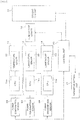
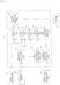
- FIG. 4 is a block diagram of the temperature management system according to the present embodiment.
- the temperature management system has temperature sensors 32, power consumption sensors 34, a temperature sensor 33, a control unit 30, a parameter setting unit 31, and a cooling fan unit 12.
- Each of the temperature sensors 32 is formed in the same chip as CPU 14a, and transmits the temperature of the CPU 14a to the control unit 30 via a communications device (not illustrated) provided in the computers 14.
- control unit 30 and the computers 14 are performed via user datagram protocol (UDP) communication.
- UDP user datagram protocol
- communication between the control unit 30 and the computers 14 is not limited to the UDP communication.
- a temperature sensor disposed in the same chip as the CPU 14a is used as the temperature sensor 32 in the present embodiment, a temperature sensor, which is disposed in close contact with the package of the CPU 14a, may be used.
- the temperature sensor 33 is disposed on the air intake surface side of the racks 13 to detect the temperature of the air supplied into the racks 13. Multiple temperature sensors 33 may be disposed on the air intake surface side of the racks 13.
- the power consumption sensors 34 each detects power consumption of a computer 14. The outputs of the temperature sensor 33 and the power consumption sensors 34 are also transmitted to the control unit 30.
- the control unit 30 includes for instance, a field-programmable gate array (FPGA) or a programmable logic controller (PLC) .
- FPGA field-programmable gate array
- PLC programmable logic controller
- a dedicated program may be read into a specific computer 14 in the racks 13, and the computer 14 may be used as the control unit 30.
- Parameters necessary for control are set to the parameter setting unit 31.
- the parameters set in the parameter setting unit 31 in the present embodiment are a target value of CPU temperature, a target value following parameter, a manipulated variable reduction parameter, and a manipulated variable change range parameter. These parameters will be described later.
- the control unit 30 determines a manipulated variable according to the outputs of the temperature sensors 32, 33, the outputs of the power consumption sensors 34, and the parameters set in the parameter setting unit 31, and controls the cooling fan unit 12 based on the manipulated variable.
- the temperature sensor 32 is an example of a first temperature detection unit, and the temperature sensor 33 is an example of a second temperature detection unit. Also, CPU 14a is an example of a heat generation component, and the cooling fan unit 12 is an example of a cooling apparatus.
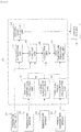
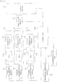
- FIG. 5 is a functional block diagram illustrating the configuration of the control unit 30.
- the control unit 30 has a high level temperature calculation unit 41, an average temperature calculation unit 42, a high level power consumption calculation unit 43, a CPU temperature prediction model unit 44, a correction unit 45, a cost function unit 46, an optimization unit 47, and a control signal generation unit 48.
- the high level temperature calculation unit 41 obtains data of CPU temperature of each computer 14 from the temperature sensors 32, and determines a high level temperature to be evaluated and outputs the determined high level temperature to the cost function unit 46 and the correction unit 45.
- the high level temperature is defined as the highest CPU temperature in the CPU temperatures obtained from the temperature sensors 32.
- the average temperature calculation unit 42 obtains data of temperature of the air supplied to the racks 13 from the temperature sensor 33. The average temperature calculation unit 42 then calculates the average value (hereinafter referred to as an "intake air temperature"), and outputs the result of the calculation to the CPU temperature prediction model unit 44.
- the high level power consumption calculation unit 43 obtains data of power consumption of each computer 14 from the power consumption sensors 34, and determines high level power consumption to be evaluated among the data and outputs the determined high level power consumption to the CPU temperature prediction model unit 44.
- the high level power consumption is defined as the highest power consumption in the power consumption of the computers 14 obtained from the power consumption sensors 34.
- the CPU temperature prediction model unit 44 uses a prediction model to predict the CPU temperature in the future based on the intake air temperature, the high level power consumption, and the manipulated variable of the cooling fans 12a.
- the correction unit 45 corrects the CPU temperature (hereinafter referred to as a "predicted CPU temperature") predicted by the temperature prediction model unit 44 using past data.
- the cost function unit 46 is set with a cost function and calculates a cost by assigning a weight to each of the deviation between a predicted CPU temperature and a target value of the CPU temperature, the change range of the manipulated variable, and the magnitude of the manipulated variable.
- the optimization unit 47 calculates a manipulated variable, which satisfies predetermined constraint conditions and minimizes the cost, based on an optimization algorithm.
- the control signal generation unit 48 generates a pulse signal for controlling the cooling fan units 12 based on the manipulated variable calculated by the optimization unit 47.
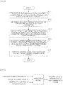
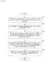
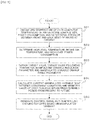
- FIG. 6 is a flow chart illustrating the operation of the temperature management system according to the present embodiment.
- the control unit 30 performs a series of processing illustrated in FIG. 6 every fixed cycle (control cycle).
- step S11 the control unit 30 obtains data of CPU temperature of each computer 14 from the temperature sensors 32. Also, the control unit 30 obtains data of the temperature of the air on the air intake surface side of the racks 13 from the temperature sensor 33, and obtains data of the power consumption of each computer 14 from the power consumption sensors 34.
- step S12 the control unit 30 determines a high level temperature, an intake air temperature, and high level power consumption.
- the high level temperature calculation unit 41 extracts the highest temperature from the CPU temperatures detected by the temperature sensors 32, and determines the highest temperature as the high level temperature. Also, the average temperature calculation unit 42 calculates the average value of the temperatures of the air on the air intake surface side of the racks 13, obtained from the temperature sensor 33, and determines the average value as the intake air temperature. In addition, the high level power consumption calculation unit 43 extracts the highest power consumption from the power consumption of the computers 14 detected by the power consumption sensors 34, and determines the highest power consumption as the high level power consumption.
- the control unit 30 obtains a target value of CPU temperature, a target value following parameter, a manipulated variable reduction parameter, and a manipulated variable change range parameter.
- the target value of CPU temperature may be lower than an allowable upper limit temperature of the CPU 14a, and is set to 90°C, for instance.
- the target value following parameter is a weight parameter for making the value of later-described cost function close to a target value.
- the manipulated variable reduction parameter is a weight parameter for making the magnitude of the manipulated variable for the cost function close to 0.
- the manipulated variable change range parameter is a weight parameter for reducing the change range of the manipulated variable for the cost function.
- step S14 the control unit 30 calculates the current manipulated variable that satisfies constraint conditions and minimizes the value of the cost function within a predetermined period from the present to the future.
- the CPU temperature prediction model unit 44 uses a prediction model to predict a CPU temperature based on a manipulated variable (command value for the revolution speed) u(k) of the cooling fans 12a, an intake air temperature v 1 (k), and a high level power consumption v 2 (k).
- a manipulated variable command value for the revolution speed
- u(k) of the cooling fans 12a an intake air temperature
- v 1 (k) an intake air temperature
- v 2 (k) a high level power consumption
- the prediction model predicts a maximum value of CPU temperature (temperature of a heat generation component) in the future based on the high level power consumption v 2 (k), the intake air temperature v 1 (k), and the manipulated variable u(k) of the cooling fans 12a.
- a maximum value of CPU temperature temperature of a heat generation component
- y(k+1) is future CPU temperature in the subsequent cycle.
- one cycle is set to 1 second.
- a state space model expressed by the following Expression (2) and Expression (3) is used.
- x k + 1 Ax k + B u u k ⁇ d t + B v v k
- y ⁇ k Cx k
- k) is called a state variable.
- v(k) [v 1 (k), v 2 (k)] T
- A is n ⁇ n matrix
- B u is an n-dimensional vector
- Bv is an n ⁇ 2 matrix
- C is a scalar.
- A, B u , B v , and C are determined by conducting an experiment beforehand to perform system identification.
- the dead time d t is set to 12 seconds.
- a model expression method may be a multiple regression equation model or may be data such as a map function.
- the correction unit 45 corrects CPU temperature predicted value tilde ⁇ y ⁇ (k+1
- k y ⁇ k + 1
- control unit 30 uses the optimization unit 47 to calculate the current manipulated variable that satisfies constraint conditions and minimizes the value of the cost function within a predetermined period p from the present to the future.
- the notation of dead time d t in manipulated variable u(k-d t ) is omitted.
- the manipulated variable u in the subsequent cycle in a future period can be expressed as in the following Expression (5) using a change amount ⁇ u in the manipulated variable.
- k u k + i ⁇ 1
- k i 0 , ... , p ⁇ 1
- i is the index that indicates a time in the future period.
- the index i is added to Expression (2), Expression (3), and Expression (4) to obtain expressions as in the following Expression (6), Expression (7), and Expression (8).
- control unit 30 uses Expression (5) to Expression (8) to calculate an input column of the change amount ⁇ u in the manipulated variable by Expression (11) below, the change amount ⁇ u satisfying the constraint conditions in the following Expression (9) and minimizing the value of the cost function J in the following Expression (10).
- p indicates a future period in which prediction is taken into consideration.
- m indicates a future period in which change in the manipulated variable is taken into consideration and p ⁇ m.
- p is set to 100 and m is set to 1.
- Q, R ⁇ u, and R u are weight matrices.
- the first term of Expression (10) indicates an operation for making the controlled variable y close to a target value r, and Q is the weight of the operation, specifically, is the target value following parameter.
- the second term in Expression (10) is the operation for making the change amount ⁇ u in the manipulated variable close to 0.
- R ⁇ u is the weight of the operation, specifically, is the manipulated variable reduction parameter.
- the change amount ⁇ u increases as R ⁇ u decreases, and the change amount ⁇ u decreases as R ⁇ u increases.
- the third term in Expression (10) is an operation for making the manipulated variable close to a target manipulated variable U target .
- U target is set to 0.
- Ru is the weight of the operation for making the manipulated variable close to the target manipulated variable U target , specifically, is the manipulated variable change range parameter.
- Expression (11) determines the optimal input column ⁇ opt (k
- a meta-heuristic numerical solution method for searching for an approximate solution such as a genetic algorithm (GA) or a particle swarm optimization (PSO) may also be used.
- G genetic algorithm
- PSO particle swarm optimization
- KWIK algorithm for solving a quadratic programming problem is used.
- step S15 the control signal generation unit 48 generates a signal for controlling the rotation of the cooling fans 12a based on the current manipulated variable u(k) obtained by the optimization unit 47.
- the optimal manipulated variable u(k) is calculated in consideration of an effect of the intake air temperature and the power consumption from the present to the future using a prediction model that predicts a temperature of a heat generation component based on the revolution speed of the fans, the intake air temperature, and the power consumption.
- the control of the cooling fan units 12 using the manipulated variable u(k) makes it possible to reduce the power consumed by the cooling fan units 12 while properly cooling the heat generation component.
- cooling fan units 12 cooling fans 12a
- the cooling fan units 12 were controlled to maintain the CPU temperature at 90°C or low while the computers 14 were operated so that CPU usage rate was alternately changed between 60% and 50% every 600 seconds.
- the comparative example indicates feed-forward control (hereinafter referred to as "FF control”) in which the manipulated variable u(k) is calculated as indicated in the following Expression (13) based on the difference between intake-side temperature T front (k) and exhaust-side temperature T back (k) of the racks 13.
- FF control feed-forward control
- FIG. 8(a) illustrates a temporal change of the CPU temperature when the cooling fans 12a are controlled in the comparative example.
- the CPU temperature is maintained at 90°C or low.
- the CPU temperature may fall to approximately 80°C, which indicates excessive cooling.
- the control over the revolution speed of the cooling fans 12a is not sufficiently optimized, and power is wastefully consumed.
- FIG. 8(b) illustrates a temporal change of the CPU temperature when the cooling fans 12a are controlled by the present embodiment.
- the CPU temperature is definitely maintained at 90°C or low, and even when the operational state of the CPU changes, the CPU temperature hardly changes and is maintained at approximately 88°C.
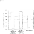
- FIG. 9 is a graph illustrating the results of research of power consumption of the cooling fan units 12 when the cooling fan units 12 are controlled according to the embodiment and the comparative examples.
- first comparative example indicates the power consumption in the case of FF control in which the manipulated variable u(k) is calculated as indicated in Expression (13) based on the difference between the intake-side temperature T front (k) and the exhaust-side temperature T back (k) of the racks 13.
- second comparative example indicates the power consumption in the case where proportional integration (PI) control is performed on the cooling fan units 12 based on the difference between the temperature of the air on the intake surface side of the racks and the temperature of the air on the exhaust surface side of the racks.
- PI proportional integration
- the power consumption was approximately 2.17 kw in the embodiment.
- the power consumption was approximately 2.64 kW
- the power consumption was approximately 2.71 kw.
- the power consumption was reduced by nearly 20% in contrast to the first and second comparative examples.
- FIG. 10 is a block diagram of a temperature management system according to a second embodiment.
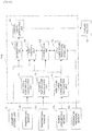
- FIG. 11 is a functional block diagram illustrating the configuration of a control unit in the temperature management system according to the second embodiment. It is to be noted that in FIG. 10 and FIG. 11 , the same components as in FIG. 4 and FIG. 5 are labeled with the same symbol, and detailed description thereof is omitted.
- the temperature management system in the present embodiment is basically the same as that of the first embodiment except for that the power consumption sensors 34 (see FIG. 4 ) is not provided.
- the high level power consumption calculation unit 43 (see FIG. 5 ) described in the first embodiment is not provided but a power consumption disturbance model unit 51 and a state estimation unit 52 are provided.
- high level power consumption is treated as unobservable disturbance and the disturbance model unit 51 is set with a disturbance model that expresses a change in the power consumption based on a change in the high level temperature.
- the state estimation unit 52 uses the prediction model and the disturbance model to estimate an operation state of the CPU.
- FIG. 12 is a flow chart illustrating the operation of the temperature management system according to the present embodiment.
- step S21 the control unit 30a obtains data of the CPU temperature of each computer 14 from the temperature sensors 32, and obtains the temperature of the air on the intake surface side of the racks 13 from the temperature sensor 33.
- step S22 the control unit 30a determines a high level temperature and an intake air temperature.
- the high level temperature calculation unit 41 extracts the highest temperature from the CPU temperatures detected by the temperature sensors 32, and determines the highest temperature as the high level temperature. Also, the average temperature calculation unit 42 calculates the average value of the temperatures of the air on the air intake surface side of the racks 13, obtained from the temperature sensor 33, and determines the average value as the intake air temperature.
- step S23 the control unit 30a obtains a target value of CPU temperature, a target value following parameter, a manipulated variable reduction parameter, and a manipulated variable change range parameter.
- step S24 the control unit 30a calculates the current manipulated variable that satisfies constraint conditions and minimizes the value of the cost function within a predetermined period from the present to the future.
- the CPU temperature prediction model unit 44 uses the prediction model and the disturbance model to predict a CPU temperature based on a manipulated variable (command value for the revolution speed) u(k) of the cooling fans 12a, an intake air temperature v 1 (k), and a high level power consumption v 2 (k).
- a manipulated variable command value for the revolution speed
- u(k) of the cooling fans 12a an intake air temperature
- v 1 (k) an intake air temperature
- v 2 (k) high level power consumption
- the prediction model is expressed by Expression (1) described above.
- y'(k+1) is a future CPU temperature in the subsequent cycle.
- the state space model expressed by the above-described Expression (2) and Expression (3) is used.
- the disturbance model defined in the power consumption disturbance model unit 51 is a model which is expressed by Expression (14) and Expression (15) and which assumes high level power consumption d(k) as random step-shaped disturbance and outputs an integration output.
- x d k + 1 A ⁇ x d k + B ⁇ d k ⁇ n d k
- d k C ⁇ x d k
- k) is the state variable of the unobservable disturbance d(k).
- the state estimation unit 52 replaces the state variable x(k
- k) is the state variable of the prediction model after the compensation
- k) is the state variable of the disturbance model after the compensation.
- M is a Kalman gain designed with a Kalman filter and is a two-dimensional vector.
- the correction unit 45 corrects CPU temperature predicted value hat ⁇ y ⁇ (k+1
- k y ⁇ k + 1
- the optimization unit 47 calculates the current manipulated variable that satisfies constraint conditions and minimizes the value of the cost function within a predetermined period from the present to the future.
- the notation of dead time d t in the manipulated variable u(k-d t ) is omitted.
- the manipulated variable u in the subsequent cycle in a future period can be expressed as in the above-described Expression (5) using the change amount ⁇ u in the manipulated variable.
- control unit 30a uses Expression (5) and Expression (20) to Expression (22) to calculate an input column of the change amount ⁇ u in the manipulated variable by Expression (11), the change amount ⁇ u satisfying the constraint conditions in Expression (9) and minimizing the value of the cost function J in Expression (10).
- step S25 the control signal unit 48 generates a signal for controlling the rotation of the cooling fans 12a based on the current manipulated variable u(k) obtained by the optimization unit 47.
- the optimal manipulated variable is calculated in consideration of an effect of the intake air temperature and the power consumption from the present to the future using a prediction model that predicts a temperature of a heat generation component based on the revolution speed of the fans, the intake air temperature, and the power consumption.
- the control of the cooling fan units 12 using the manipulated variable u(k) makes it possible to reduce the power consumed by the cooling fan units 12 while properly cooling the heat generation component.
- a power consumption sensor is unnecessary, and thus there is also an advantage in that the system is simplified compared with the first embodiment.
- FIG. 13 is a block diagram of a temperature management system according to a third embodiment.
- FIG. 14 is a functional block diagram illustrating the configuration of a control unit in the temperature management system according to the third embodiment. It is to be noted that in FIG. 13 and FIG. 14 , the same components as in FIG. 4 and FIG. 5 are labeled with the same symbol, and detailed description thereof is omitted.
- the temperature management system in the present embodiment has a differential pressure sensor 35 that detects a differential pressure between the front and back sides of the racks 13. Also, as seen from FIG. 13 , in a control unit 30b of the temperature management system in the present embodiment, a signal outputted from the differential pressure sensor 35 is inputted to the CPU temperature prediction model unit 44.
- the differential pressure sensor 35 is an example of a pressure difference detection unit.
- FIG. 15 is a flow chart illustrating the operation of the temperature management system according to the present embodiment.
- step S31 the control unit 30b obtains data of the CPU temperature of each computer 14 from the temperature sensors 32, and obtains data of the temperature of the air on the intake surface side of the racks 13 from the temperature sensor 33. Also, the control unit 330b obtains data of the power consumption of each computer 14 from the power consumption sensors 34, and obtains data of a differential pressure (difference between the pressures on the air intake surface side and the air exhaust surface side of the racks 13) from the differential pressure sensor 35.
- step S32 the control unit 30b determines a high level temperature, an intake air temperature, and high level power consumption.
- the high level temperature calculation unit 41 extracts the highest temperature from the CPU temperatures detected by the temperature sensors 32, and determines the highest temperature as the high level temperature. Also, the average temperature calculation unit 42 calculates the average value of the temperatures of the air on the air intake surface side of the racks 13, obtained from the temperature sensor 33, and determines the average value as the intake air temperature. In addition, the high level power consumption calculation unit 43 extracts the highest power consumption from the power consumption of the computers 14 detected by the power consumption sensors 34, and determines the highest power consumption as the high level power consumption.
- step S33 the control unit 30b obtains a target value of CPU temperature, a target following parameter, a manipulated variable reduction parameter, and a manipulated variable change range parameter.
- step S34 the control unit 30b calculates the current manipulated variable that satisfies constraint conditions and minimizes the value of the cost function within a predetermined period from the present to the future.
- the CPU temperature prediction model unit 44 uses the prediction model to predict a CPU temperature based on the manipulated variable (command value for the revolution speed) u(k) of the cooling fans 12a, the intake air temperature v 1 (k), the high level power consumption v 2 (k), and a differential pressure v 3 (k) between the front and back sides of the racks 14.
- y(k+1) is a future CPU temperature in the subsequent cycle.
- one cycle is also set to 1 second.
- k) is called a state function.
- v(k) [v 1 (k), v 2 (k), v 3 (k)] T .
- A is n ⁇ n matrix
- B u is an n-dimensional vector
- B v is an n ⁇ 2 matrix
- C is a scalar.
- A, B u , B v , and C are determined by conducting an experiment beforehand to perform system identification.
- the correction unit 45 corrects CPU temperature predicted value tilde ⁇ y ⁇ (k+1
- the optimization unit 47 calculates the current manipulated variable that satisfies constraint conditions and minimizes the value of the cost function within a predetermined period from the present to the future.
- the notation of dead time d t in the manipulated variable u(k-d t ) is omitted.
- the manipulated variable u in the subsequent cycle in a future period can be expressed as in the above-described Expression (5) using the change amount ⁇ u in the manipulated variable.
- the index i is added to Expression (2), Expression (3), and Expression (4) to obtain expressions as in Expression (6), Expression (7), and Expression (8).
- control unit 30b uses those Expression (5) to Expression (8) to calculate an input column of the change amount ⁇ u in the manipulated variable by Expression (11), the change amount ⁇ u satisfying the constraint conditions in Expression (9) and minimizing the value of the cost function J in Expression (10).
- step S35 the control signal generation unit 48 generates a signal for controlling the rotation of the cooling fans 12a based on the current manipulated variable u(k) obtained by the optimization unit 47.
- the optimal manipulated variable u(k) is calculated based on the revolution speed of the fans, the intake air temperature, the power consumption, and the difference between the pressures on the air intake surface side and the air exhaust surface side of the racks 13.
- the control of the cooling fan units 12 using the manipulated variable u(k) makes it possible to reduce the power consumed by the cooling fan units 12 while properly cooling the heat generation component.
- change of the differential pressure between the front and back sides of the racks 14 is taken into consideration to determine the manipulated variable of the cooling fan units 12, and thus an optimal manipulated variable including an effect such as clogging of a filter is obtainable.
Landscapes
- Engineering & Computer Science (AREA)
- Physics & Mathematics (AREA)
- General Engineering & Computer Science (AREA)
- Theoretical Computer Science (AREA)
- General Physics & Mathematics (AREA)
- Computer Hardware Design (AREA)
- Thermal Sciences (AREA)
- Microelectronics & Electronic Packaging (AREA)
- Automation & Control Theory (AREA)
- Human Computer Interaction (AREA)
- Remote Sensing (AREA)
- Cooling Or The Like Of Electrical Apparatus (AREA)
Claims (10)
- Temperaturregelungssystem, umfassend:eine erste Temperaturerfassungseinheit (32), die zum Erfassen einer Temperatur einer Wärmeerzeugungskomponente (14a) in einer elektronischen Vorrichtung (14) konfiguriert ist;eine Kühleinrichtung (12), die konfiguriert ist, Luft in der elektronischen Vorrichtung (14) zirkulieren zu lassen und die Wärmeerzeugungskomponente (14a) zu kühlen;eine zweite Temperaturerfassungseinheit (33), die zum Erfassen einer Temperatur der in der elektronischen Vorrichtung (14) strömenden Luft konfiguriert ist;eine Parametereinstelleinheit (31), die konfiguriert ist, einen Zielwert der Temperatur der Wärmeerzeugungskomponente (14a) einzustellen, undeine Steuereinheit (30, 30a, 30b), die konfiguriert ist, einen vorhergesagten Wert einer zukünftigen Temperatur der Wärmeerzeugungskomponente (14a) basierend auf Ausgaben der ersten Temperaturerfassungseinheit (32) und der zweiten Temperaturerfassungseinheit (33) und einen Stromverbrauch der elektronischen Vorrichtung (14) zu berechnen, und konfiguriert ist, eine Stellgröße der Kühlvorrichtung (12) basierend auf dem vorhergesagten Wert und dem Zielwert zu bestimmen, und dadurch gekennzeichnet, dass die Steuereinheit (30, 30a, 30b) Folgendes aufweist:eine Vorhersagemodelleinheit (44), die mit einem Vorhersagemodell eingestellt ist, um den vorhergesagten Wert der zukünftigen Temperatur der Wärmeerzeugungskomponente (14a) basierend auf der Temperatur der in der elektronischen Vorrichtung (14) strömenden Luft, der Stellgröße und dem Stromverbrauch der elektronischen Vorrichtung (14) zu berechnen, und konfiguriert ist, den vorhergesagten Wert unter Verwendung des Vorhersagemodells zu berechnen;
eine Korrektureinheit (45), die konfiguriert ist, den von der Vorhersagemodelleinheit (44) berechneten vorhergesagten Wert zu korrigieren;
eine Kostenfunktionseinheit (46), die mit einer Kostenfunktion eingestellt ist, um eine Kostenberechnung durchzuführen, indem einer Abweichung zwischen dem von der Korrektureinheit (45) korrigierten vorhergesagten Wert und dem Zielwert eine Gewichtung zugewiesen wird, und konfiguriert ist, die Kosten unter Verwendung der Kostenfunktion zu berechnen; und
eine Optimierungseinheit (47), die konfiguriert ist, einen Änderungsbetrag der Stellgröße zu berechnen, der eine voreingestellte Randbedingung erfüllt und die von der Kostenfunktionseinheit (46) berechneten Kosten innerhalb eines vorbestimmten Zeitraums von der Gegenwart bis zur Zukunft minimiert, und die Stellgröße der Kühlvorrichtung (12) basierend auf dem Änderungsbetrag zu berechnen. - Temperaturregelungssystem nach Anspruch 1, wobei
das System ferner eine Stromverbrauchserfassungseinheit (34) umfasst, die zum Erfassen des Stromverbrauchs der elektronischen Vorrichtung (14) konfiguriert ist, und
eine Ausgabe der Stromverbrauchserfassungseinheit (34) an die Vorhersagemodelleinheit (44) der Steuereinheit (30, 30b) übertragen wird. - Temperaturregelungssystem nach Anspruch 2, wobei
die Steuereinheit (30, 30b) Folgendes aufweist:eine Hochtemperaturberechnungseinheit (41), die konfiguriert ist, eine zu bewertende Hochtemperatur aus der Ausgabe der ersten Temperaturerfassungseinheit (32) zu bestimmen; undeine Hochstromverbrauchsberechnungseinheit (43), die zum Bestimmen eines zu bewertenden Hochstromverbrauchs aus der Ausgabe der Stromverbrauchserfassungseinheit (34) konfiguriert ist. - Temperaturregelungssystem nach Anspruch 3, wobei
die Vorhersagemodelleinheit (41) konfiguriert ist, den vorhergesagten Wert der zukünftigen Temperatur der Wärmeerzeugungskomponente (14a) basierend auf der Temperatur der in der elektronischen Vorrichtung (14) strömenden Luft, der Stellgröße und dem Hochstromverbrauch zu berechnen, und
die Korrektureinheit (45) konfiguriert ist, einen gegenwärtigen vorhergesagten Wert unter Verwendung einer Differenz zwischen einer vergangenen Hochtemperatur und einem vergangenen vorhergesagten Wert zu korrigieren. - Temperaturregelungssystem nach Anspruch 1, wobei
Das System ferner eine Hochtemperaturberechnungseinheit (41) umfasst, die konfiguriert ist, eine zu bewertende Hochtemperatur aus der Ausgabe der ersten Temperaturerfassungseinheit (32) zu bestimmen,
die Steuereinheit (30a) Folgendes aufweist:eine Störungsmodelleinheit (51), die mit einem Störungsmodell eingestellt ist, um den Stromverbrauch der elektronischen Vorrichtung (14) als nicht beobachtbare Störung basierend auf einer Veränderung der Hochtemperaturtemperatur auszudrücken; undeine Zustandsschätzeinheit (52), die zum Schätzen eines Betriebszustands der elektronischen Vorrichtung (14) unter Verwendung des Störungsmodells und des Vorhersagemodells konfiguriert ist, wobei die Vorhersagemodelleinheit (44) konfiguriert ist, den vorhergesagten Wertes unter Verwendung des Betriebszustands zu berechnen, der von der Zustandsschätzeinheit (52) geschätzt wird, undwobei die Korrektureinheit (45) konfiguriert ist, einen gegenwärtigen vorhergesagten Wert unter Verwendung einer Differenz zwischen einer vergangenen Hochtemperatur und einem vergangenen vorhergesagten Wert zu korrigieren. - Temperaturregelungssystem nach Anspruch 1, wobei das System ferner eine Druckdifferenzerfassungseinheit (35) umfasst, die konfiguriert ist, eine Druckdifferenz zwischen einer Einlassflächenseite und einer Auslassflächenseite der elektronischen Vorrichtung (14) zu erfassen, und
die Vorhersagemodelleinheit (44) konfiguriert ist, eine Ausgabe der Druckdifferenzerfassungseinheit (35) zu verwenden, wenn die Temperatur der Wärmeerzeugungskomponente (14a) vorhergesagt wird. - Temperaturregelungssystem nach einem der Ansprüche 1 bis 6, wobei die Kostenfunktion einen Zielwertfolgeparameter aufweist, um eine Regelgröße nahe an den Zielwert anzunähern, einen Stellgrößenreduzierungsparameter, um einen Änderungsbetrag in der Stellgröße nahe an 0 anzunähern, und einen Stellgrößenänderungsbereichsparameter, um die Stellgröße nahe an eine Zielstellgröße anzunähern.
- Temperaturregelungssystem nach einem der Ansprüche 1 bis 7, wobei
Die elektronische Vorrichtung ein Computer (14) ist, der in einem Rack (13) untergebracht ist, und
die Wärmeerzeugungskomponente eine CPU (14a) ist. - Temperaturregelungssystem nach Anspruch 8,
wobei eine Mehrzahl der elektronischen Vorrichtungen (14) in dem Rack (13) untergebracht ist. - Temperaturregelungssystem nach Anspruch 9, wobei
das Rack (13) in einer Struktur (10) angeordnet ist, die mit einer Einlassöffnung (11a) und einer Auslassöffnung (11b) versehen ist, die mit dem Außenbereich kommunizieren, und
die Kühlvorrichtung (12) konfiguriert ist, Luft in die elektronische Vorrichtung (14) zuzuführen, wobei die Luft durch die Einlassöffnung (11a) in die Struktur (10) eingeleitet wird.
Applications Claiming Priority (1)
| Application Number | Priority Date | Filing Date | Title |
|---|---|---|---|
| PCT/JP2013/057595 WO2014147691A1 (ja) | 2013-03-18 | 2013-03-18 | 温度管理システム |
Publications (3)
| Publication Number | Publication Date |
|---|---|
| EP2977852A1 EP2977852A1 (de) | 2016-01-27 |
| EP2977852A4 EP2977852A4 (de) | 2016-05-04 |
| EP2977852B1 true EP2977852B1 (de) | 2019-03-13 |
Family
ID=51579431
Family Applications (1)
| Application Number | Title | Priority Date | Filing Date |
|---|---|---|---|
| EP13878781.7A Not-in-force EP2977852B1 (de) | 2013-03-18 | 2013-03-18 | Temperaturregelungssystem |
Country Status (4)
| Country | Link |
|---|---|
| US (1) | US9958916B2 (de) |
| EP (1) | EP2977852B1 (de) |
| JP (1) | JP5994927B2 (de) |
| WO (1) | WO2014147691A1 (de) |
Families Citing this family (38)
| Publication number | Priority date | Publication date | Assignee | Title |
|---|---|---|---|---|
| JP6136596B2 (ja) * | 2013-06-05 | 2017-05-31 | 富士通株式会社 | 監視制御装置、監視制御方法及び監視制御プログラム |
| US11162912B2 (en) | 2015-09-11 | 2021-11-02 | KABUSHI Kl KAISHA TOSHIBA | Electronic apparatus, index calculating method, and computer program product |
| US9820409B1 (en) * | 2015-09-28 | 2017-11-14 | Amazon Technologies, Inc. | Rack cooling system |
| US10368466B1 (en) * | 2015-10-06 | 2019-07-30 | Amazon Technologies, Inc. | Rack mountable cooling canister |
| TW201714042A (zh) * | 2015-10-13 | 2017-04-16 | 鴻海精密工業股份有限公司 | 貨櫃型資料中心 |
| US10222843B1 (en) * | 2016-03-16 | 2019-03-05 | ZT Group Int'l, Inc. | Server platform thermal control system using component power |
| US10585466B1 (en) | 2016-03-16 | 2020-03-10 | ZT Group Int'l, Inc. | Power saving fan control with anti fan-oscillation feature |
| US11216048B1 (en) | 2016-03-16 | 2022-01-04 | ZT Group Int'l, Inc. | System and method for controlling computer cooling using ideal cooling system settings, actual cooling system settings, and computer component data |
| JP2017195494A (ja) * | 2016-04-20 | 2017-10-26 | 富士通株式会社 | ラインカード及びラインカード制御方法 |
| US10303139B2 (en) * | 2016-06-01 | 2019-05-28 | Creative Esp Incorporated | System and method for managing electrical components for energy usage |
| US10394294B2 (en) * | 2016-08-25 | 2019-08-27 | Microchip Technology Incorporated | Predictive thermal control management using temperature and power sensors |
| JP2018060271A (ja) * | 2016-10-03 | 2018-04-12 | 富士通株式会社 | 管理装置、管理装置の制御方法、管理装置の制御プログラム及び情報処理システム |
| US11076509B2 (en) | 2017-01-24 | 2021-07-27 | The Research Foundation for the State University | Control systems and prediction methods for it cooling performance in containment |
| US10059215B1 (en) | 2017-03-08 | 2018-08-28 | A3 Labs, Llc | Energy source supply systems, energy source supply devices, and related methods |
| KR102474460B1 (ko) * | 2017-08-23 | 2022-12-07 | 삼성전자 주식회사 | 전자 장치 및 전자 장치의 동작 제어 방법 |
| US10613600B2 (en) * | 2017-11-02 | 2020-04-07 | Microsoft Technology Licensing, Llc | Advanced power based thermal control systems |
| JP6923803B2 (ja) | 2017-12-06 | 2021-08-25 | 富士通株式会社 | 情報処理装置、省電力移行プログラム、及び、省電力移行方法 |
| CN109032301A (zh) * | 2018-08-02 | 2018-12-18 | 郑州云海信息技术有限公司 | 一种通用的服务器自动散热调控系统及方法 |
| CN109189190B (zh) * | 2018-10-16 | 2020-07-14 | 西安交通大学 | 一种基于温度预测的数据中心热量管理方法 |
| JP6974291B2 (ja) * | 2018-11-09 | 2021-12-01 | 東芝三菱電機産業システム株式会社 | 半導体装置 |
| EP3943827A4 (de) * | 2019-03-18 | 2022-05-11 | NEC Corporation | Datencenterklimatisierungssteuerungsvorrichtung, verfahren, nichtflüchtiges computerlesbares medium und klimatisierungssystem |
| CN113853586A (zh) * | 2019-03-28 | 2021-12-28 | 西门子股份公司 | 用于监视电子设备的健康的热管理系统、方法和设备 |
| EP3734413B1 (de) * | 2019-04-30 | 2024-07-17 | Ovh | Verfahren und system zur überwachung des gesundheitszustandes eines serverinfrastruktur |
| CN110543196B (zh) * | 2019-08-13 | 2021-02-12 | 华为技术有限公司 | 一种散热元件的控制方法及控制装置 |
| CN112443507B (zh) * | 2019-08-30 | 2022-06-28 | 宏碁股份有限公司 | 智能风扇转速调整方法、电脑装置及服务器 |
| CN111026603B (zh) * | 2019-10-25 | 2021-04-23 | 南京大学 | 片上网络温度预测方法及装置、设备、存储介质 |
| CN111796647B (zh) * | 2020-06-30 | 2022-11-18 | 联想(北京)有限公司 | 一种检测方法及电子设备 |
| JP2022044506A (ja) * | 2020-09-07 | 2022-03-17 | 株式会社日立製作所 | 電子機器、ファン制御方法及びプログラム |
| US11946661B2 (en) * | 2021-01-29 | 2024-04-02 | Robert M. Rohde | Variable airflow energy efficient HVAC systems and methods |
| CN113534703B (zh) * | 2021-07-07 | 2022-12-06 | 国网福建省电力有限公司检修分公司 | 一种暖通组合机节能系统及其控制方法 |
| EP4403004A4 (de) * | 2021-09-16 | 2026-01-07 | Vertiv Corp | Systeme und verfahren zur umgebungssteuerung eines gehäuses |
| CN113993343B (zh) * | 2021-10-11 | 2024-10-11 | 科华数据股份有限公司 | 制冷设备的节能控制方法、装置、终端及存储介质 |
| CN114355999B (zh) * | 2021-12-24 | 2023-05-23 | 交控科技股份有限公司 | 应用于列车的智能温度控制机柜、控制方法、设备 |
| US12086001B2 (en) | 2022-05-19 | 2024-09-10 | Honeywell International Inc. | System and method for proactively controlling an environmental condition in a server rack of a data center based at least in part on server load |
| CN114777958B (zh) * | 2022-06-20 | 2022-10-28 | 深圳比特微电子科技有限公司 | 芯片散热状况检测方法、装置、电子设备及存储介质 |
| CN115266817B (zh) * | 2022-07-05 | 2026-04-21 | 清华大学 | 高温热管性能的检测方法、装置、电子设备及存储介质 |
| WO2025203571A1 (ja) * | 2024-03-29 | 2025-10-02 | Ntt株式会社 | 制御装置 |
| CN118655928B (zh) * | 2024-08-16 | 2024-11-01 | 安徽触威电子科技有限公司 | 一种防火电子显示屏智能温控控制方法及系统 |
Family Cites Families (24)
| Publication number | Priority date | Publication date | Assignee | Title |
|---|---|---|---|---|
| KR910004393B1 (ko) * | 1987-04-22 | 1991-06-27 | 미츠비시 덴키 가부시키가이샤 | 멀티 냉동사이클의 주파수 제어장치 |
| US5486995A (en) * | 1994-03-17 | 1996-01-23 | Dow Benelux N.V. | System for real time optimization |
| JP3769200B2 (ja) | 2001-03-06 | 2006-04-19 | インターナショナル・ビジネス・マシーンズ・コーポレーション | 冷却ファンの制御方法および装置 |
| US6721672B2 (en) * | 2002-01-02 | 2004-04-13 | American Power Conversion | Method and apparatus for preventing overloads of power distribution networks |
| JP4152348B2 (ja) * | 2004-06-03 | 2008-09-17 | 株式会社ソニー・コンピュータエンタテインメント | 電子デバイス冷却装置、電子デバイスシステムおよび電子デバイス冷却方法 |
| US7347621B2 (en) * | 2004-07-16 | 2008-03-25 | International Business Machines Corporation | Method and system for real-time estimation and prediction of the thermal state of a microprocessor unit |
| US7138781B2 (en) * | 2004-11-24 | 2006-11-21 | Standard Microsystems Corporation | Adaptive controller for PC cooling fans |
| US7490479B2 (en) * | 2005-03-30 | 2009-02-17 | Intel Corporation | Method and system of advanced fan speed control |
| US8374730B2 (en) * | 2005-08-25 | 2013-02-12 | Apple Inc. | Methods and apparatuses for dynamic thermal control |
| US8762097B2 (en) * | 2006-08-04 | 2014-06-24 | Apple Inc. | Method and apparatus for a thermal control system based on virtual temperature sensor |
| JP4807352B2 (ja) * | 2007-12-25 | 2011-11-02 | 三菱電機株式会社 | 温度検出システム |
| WO2009137215A2 (en) * | 2008-05-05 | 2009-11-12 | Carrier Corporation | Integrated computer equipment container and cooling unit |
| JP5189921B2 (ja) * | 2008-08-02 | 2013-04-24 | レノボ・シンガポール・プライベート・リミテッド | コンピュータの放熱システム |
| US8190276B2 (en) * | 2008-11-21 | 2012-05-29 | Oracle America, Inc. | Method and apparatus for controlling temperature variations in a computer system |
| US9069345B2 (en) * | 2009-01-23 | 2015-06-30 | Mks Instruments, Inc. | Controlling a manufacturing process with a multivariate model |
| US8086359B2 (en) * | 2009-02-23 | 2011-12-27 | Novell, Inc. | Dynamic thermal load balancing |
| JP5375948B2 (ja) | 2009-03-19 | 2013-12-25 | 富士通株式会社 | 冷却装置を有する電子装置および冷却プログラム |
| JP5206602B2 (ja) * | 2009-06-30 | 2013-06-12 | 富士通株式会社 | 空調制御装置、空調制御方法及び空調制御プログラム |
| GB0922095D0 (en) * | 2009-12-17 | 2010-02-03 | Bripco Bvba | Data centre building and rack therefor |
| JP2011257116A (ja) | 2010-06-11 | 2011-12-22 | Fujitsu Ltd | 電算機室空調システム、その制御装置、プログラム |
| US8868250B2 (en) * | 2010-09-28 | 2014-10-21 | Cisco Technology, Inc. | Fan speed control |
| JP5672099B2 (ja) * | 2011-03-22 | 2015-02-18 | 富士通株式会社 | 電子機器を搭載した装置、電子機器を搭載した装置の冷却プログラム及び電子機器を搭載した装置の冷却方法 |
| US9195243B2 (en) * | 2011-05-24 | 2015-11-24 | Aten International Co., Ltd. | System and method of safe and effective energy usage and conservation for data centers with rack power distribution units |
| US8600561B1 (en) * | 2012-09-30 | 2013-12-03 | Nest Labs, Inc. | Radiant heating controls and methods for an environmental control system |
-
2013
- 2013-03-18 WO PCT/JP2013/057595 patent/WO2014147691A1/ja not_active Ceased
- 2013-03-18 EP EP13878781.7A patent/EP2977852B1/de not_active Not-in-force
- 2013-03-18 JP JP2015506379A patent/JP5994927B2/ja not_active Expired - Fee Related
-
2015
- 2015-09-10 US US14/849,953 patent/US9958916B2/en active Active
Non-Patent Citations (1)
| Title |
|---|
| None * |
Also Published As
| Publication number | Publication date |
|---|---|
| WO2014147691A1 (ja) | 2014-09-25 |
| JP5994927B2 (ja) | 2016-09-21 |
| US20150378404A1 (en) | 2015-12-31 |
| EP2977852A4 (de) | 2016-05-04 |
| JPWO2014147691A1 (ja) | 2017-02-16 |
| US9958916B2 (en) | 2018-05-01 |
| EP2977852A1 (de) | 2016-01-27 |
Similar Documents
| Publication | Publication Date | Title |
|---|---|---|
| EP2977852B1 (de) | Temperaturregelungssystem | |
| US9645622B2 (en) | Temperature management system | |
| CN116126052B (zh) | 用于温度控制的方法、装置、设备和存储介质 | |
| EP2606406B1 (de) | Optimale energiesteuerungsoptionen für hvac-systeme | |
| US20190200489A1 (en) | Controlling operational parameters of a cooling unit | |
| US10061365B2 (en) | Temperature prediction system using prediction models, temperature prediction method using prediction models, and non-transitory computer readable recording medium having therein program for temperature prediction using prediction models | |
| US8897925B2 (en) | Heat dissipation control system and control method thereof | |
| EP2787801B1 (de) | Gestell für elektronische vorrichtung und informationsverarbeitungsvorrichtung | |
| Asad et al. | Degree of freedom based set-point reset scheme for HVAC real-time optimization | |
| JP7088323B2 (ja) | サーバラック、制御装置、冷却方法、及びプログラム | |
| JP5467929B2 (ja) | 関数生成装置、及び関数生成方法 | |
| JP6083305B2 (ja) | 電子機器冷却システム | |
| Wang et al. | Phyllis: Physics-informed lifelong reinforcement learning for data center cooling control | |
| JP2015162098A (ja) | 空調制御システム及び空調制御方法 | |
| Park et al. | Enhancing cold storage efficiency: Continuous deep deterministic policy gradient approach to energy optimization utilizing strategic sensor input data | |
| US11408626B2 (en) | Central plant control system with dynamic computation reduction | |
| Yang et al. | A Deep Reinforcement Learning Framework for Optimizing Data Center Cooling Systems | |
| Sundaralingam et al. | Server heat load based CRAC fan controller paired with rear door heat exchanger | |
| CN119155957A (zh) | 一种数据中心节能冷却控制方法及系统 | |
| CN121008632A (zh) | 温度调控方法和装置、计算机程序产品、电子设备 |
Legal Events
| Date | Code | Title | Description |
|---|---|---|---|
| PUAI | Public reference made under article 153(3) epc to a published international application that has entered the european phase |
Free format text: ORIGINAL CODE: 0009012 |
|
| 17P | Request for examination filed |
Effective date: 20150911 |
|
| AK | Designated contracting states |
Kind code of ref document: A1 Designated state(s): AL AT BE BG CH CY CZ DE DK EE ES FI FR GB GR HR HU IE IS IT LI LT LU LV MC MK MT NL NO PL PT RO RS SE SI SK SM TR |
|
| AX | Request for extension of the european patent |
Extension state: BA ME |
|
| A4 | Supplementary search report drawn up and despatched |
Effective date: 20160404 |
|
| RIC1 | Information provided on ipc code assigned before grant |
Ipc: H05K 7/20 20060101ALI20160329BHEP Ipc: G06F 1/20 20060101AFI20160329BHEP Ipc: G05D 23/19 20060101ALI20160329BHEP Ipc: F24F 7/06 20060101ALI20160329BHEP Ipc: H01L 23/467 20060101ALI20160329BHEP |
|
| DAX | Request for extension of the european patent (deleted) | ||
| GRAP | Despatch of communication of intention to grant a patent |
Free format text: ORIGINAL CODE: EPIDOSNIGR1 |
|
| STAA | Information on the status of an ep patent application or granted ep patent |
Free format text: STATUS: GRANT OF PATENT IS INTENDED |
|
| INTG | Intention to grant announced |
Effective date: 20181019 |
|
| RIN1 | Information on inventor provided before grant (corrected) |
Inventor name: ENDO, HIROSHI Inventor name: OGAWA, MASATOSHI Inventor name: KONDO, MASAO Inventor name: FUKUDA, HIROYUKI |
|
| GRAS | Grant fee paid |
Free format text: ORIGINAL CODE: EPIDOSNIGR3 |
|
| GRAA | (expected) grant |
Free format text: ORIGINAL CODE: 0009210 |
|
| STAA | Information on the status of an ep patent application or granted ep patent |
Free format text: STATUS: THE PATENT HAS BEEN GRANTED |
|
| AK | Designated contracting states |
Kind code of ref document: B1 Designated state(s): AL AT BE BG CH CY CZ DE DK EE ES FI FR GB GR HR HU IE IS IT LI LT LU LV MC MK MT NL NO PL PT RO RS SE SI SK SM TR |
|
| REG | Reference to a national code |
Ref country code: GB Ref legal event code: FG4D |
|
| REG | Reference to a national code |
Ref country code: CH Ref legal event code: EP Ref country code: AT Ref legal event code: REF Ref document number: 1108569 Country of ref document: AT Kind code of ref document: T Effective date: 20190315 |
|
| REG | Reference to a national code |
Ref country code: IE Ref legal event code: FG4D |
|
| REG | Reference to a national code |
Ref country code: DE Ref legal event code: R096 Ref document number: 602013052478 Country of ref document: DE |
|
| REG | Reference to a national code |
Ref country code: NL Ref legal event code: MP Effective date: 20190313 |
|
| REG | Reference to a national code |
Ref country code: LT Ref legal event code: MG4D |
|
| PG25 | Lapsed in a contracting state [announced via postgrant information from national office to epo] |
Ref country code: SE Free format text: LAPSE BECAUSE OF FAILURE TO SUBMIT A TRANSLATION OF THE DESCRIPTION OR TO PAY THE FEE WITHIN THE PRESCRIBED TIME-LIMIT Effective date: 20190313 Ref country code: NO Free format text: LAPSE BECAUSE OF FAILURE TO SUBMIT A TRANSLATION OF THE DESCRIPTION OR TO PAY THE FEE WITHIN THE PRESCRIBED TIME-LIMIT Effective date: 20190613 Ref country code: LT Free format text: LAPSE BECAUSE OF FAILURE TO SUBMIT A TRANSLATION OF THE DESCRIPTION OR TO PAY THE FEE WITHIN THE PRESCRIBED TIME-LIMIT Effective date: 20190313 Ref country code: FI Free format text: LAPSE BECAUSE OF FAILURE TO SUBMIT A TRANSLATION OF THE DESCRIPTION OR TO PAY THE FEE WITHIN THE PRESCRIBED TIME-LIMIT Effective date: 20190313 |
|
| PG25 | Lapsed in a contracting state [announced via postgrant information from national office to epo] |
Ref country code: BG Free format text: LAPSE BECAUSE OF FAILURE TO SUBMIT A TRANSLATION OF THE DESCRIPTION OR TO PAY THE FEE WITHIN THE PRESCRIBED TIME-LIMIT Effective date: 20190613 Ref country code: RS Free format text: LAPSE BECAUSE OF FAILURE TO SUBMIT A TRANSLATION OF THE DESCRIPTION OR TO PAY THE FEE WITHIN THE PRESCRIBED TIME-LIMIT Effective date: 20190313 Ref country code: NL Free format text: LAPSE BECAUSE OF FAILURE TO SUBMIT A TRANSLATION OF THE DESCRIPTION OR TO PAY THE FEE WITHIN THE PRESCRIBED TIME-LIMIT Effective date: 20190313 Ref country code: LV Free format text: LAPSE BECAUSE OF FAILURE TO SUBMIT A TRANSLATION OF THE DESCRIPTION OR TO PAY THE FEE WITHIN THE PRESCRIBED TIME-LIMIT Effective date: 20190313 Ref country code: HR Free format text: LAPSE BECAUSE OF FAILURE TO SUBMIT A TRANSLATION OF THE DESCRIPTION OR TO PAY THE FEE WITHIN THE PRESCRIBED TIME-LIMIT Effective date: 20190313 Ref country code: GR Free format text: LAPSE BECAUSE OF FAILURE TO SUBMIT A TRANSLATION OF THE DESCRIPTION OR TO PAY THE FEE WITHIN THE PRESCRIBED TIME-LIMIT Effective date: 20190614 |
|
| REG | Reference to a national code |
Ref country code: AT Ref legal event code: MK05 Ref document number: 1108569 Country of ref document: AT Kind code of ref document: T Effective date: 20190313 |
|
| PG25 | Lapsed in a contracting state [announced via postgrant information from national office to epo] |
Ref country code: SK Free format text: LAPSE BECAUSE OF FAILURE TO SUBMIT A TRANSLATION OF THE DESCRIPTION OR TO PAY THE FEE WITHIN THE PRESCRIBED TIME-LIMIT Effective date: 20190313 Ref country code: IT Free format text: LAPSE BECAUSE OF FAILURE TO SUBMIT A TRANSLATION OF THE DESCRIPTION OR TO PAY THE FEE WITHIN THE PRESCRIBED TIME-LIMIT Effective date: 20190313 Ref country code: EE Free format text: LAPSE BECAUSE OF FAILURE TO SUBMIT A TRANSLATION OF THE DESCRIPTION OR TO PAY THE FEE WITHIN THE PRESCRIBED TIME-LIMIT Effective date: 20190313 Ref country code: ES Free format text: LAPSE BECAUSE OF FAILURE TO SUBMIT A TRANSLATION OF THE DESCRIPTION OR TO PAY THE FEE WITHIN THE PRESCRIBED TIME-LIMIT Effective date: 20190313 Ref country code: AL Free format text: LAPSE BECAUSE OF FAILURE TO SUBMIT A TRANSLATION OF THE DESCRIPTION OR TO PAY THE FEE WITHIN THE PRESCRIBED TIME-LIMIT Effective date: 20190313 Ref country code: PT Free format text: LAPSE BECAUSE OF FAILURE TO SUBMIT A TRANSLATION OF THE DESCRIPTION OR TO PAY THE FEE WITHIN THE PRESCRIBED TIME-LIMIT Effective date: 20190713 Ref country code: CZ Free format text: LAPSE BECAUSE OF FAILURE TO SUBMIT A TRANSLATION OF THE DESCRIPTION OR TO PAY THE FEE WITHIN THE PRESCRIBED TIME-LIMIT Effective date: 20190313 Ref country code: RO Free format text: LAPSE BECAUSE OF FAILURE TO SUBMIT A TRANSLATION OF THE DESCRIPTION OR TO PAY THE FEE WITHIN THE PRESCRIBED TIME-LIMIT Effective date: 20190313 |
|
| REG | Reference to a national code |
Ref country code: CH Ref legal event code: PL |
|
| PG25 | Lapsed in a contracting state [announced via postgrant information from national office to epo] |
Ref country code: LU Free format text: LAPSE BECAUSE OF NON-PAYMENT OF DUE FEES Effective date: 20190318 Ref country code: SM Free format text: LAPSE BECAUSE OF FAILURE TO SUBMIT A TRANSLATION OF THE DESCRIPTION OR TO PAY THE FEE WITHIN THE PRESCRIBED TIME-LIMIT Effective date: 20190313 Ref country code: PL Free format text: LAPSE BECAUSE OF FAILURE TO SUBMIT A TRANSLATION OF THE DESCRIPTION OR TO PAY THE FEE WITHIN THE PRESCRIBED TIME-LIMIT Effective date: 20190313 |
|
| REG | Reference to a national code |
Ref country code: BE Ref legal event code: MM Effective date: 20190331 |
|
| REG | Reference to a national code |
Ref country code: DE Ref legal event code: R097 Ref document number: 602013052478 Country of ref document: DE |
|
| PG25 | Lapsed in a contracting state [announced via postgrant information from national office to epo] |
Ref country code: AT Free format text: LAPSE BECAUSE OF FAILURE TO SUBMIT A TRANSLATION OF THE DESCRIPTION OR TO PAY THE FEE WITHIN THE PRESCRIBED TIME-LIMIT Effective date: 20190313 Ref country code: IS Free format text: LAPSE BECAUSE OF FAILURE TO SUBMIT A TRANSLATION OF THE DESCRIPTION OR TO PAY THE FEE WITHIN THE PRESCRIBED TIME-LIMIT Effective date: 20190713 |
|
| PLBE | No opposition filed within time limit |
Free format text: ORIGINAL CODE: 0009261 |
|
| STAA | Information on the status of an ep patent application or granted ep patent |
Free format text: STATUS: NO OPPOSITION FILED WITHIN TIME LIMIT |
|
| PG25 | Lapsed in a contracting state [announced via postgrant information from national office to epo] |
Ref country code: DK Free format text: LAPSE BECAUSE OF FAILURE TO SUBMIT A TRANSLATION OF THE DESCRIPTION OR TO PAY THE FEE WITHIN THE PRESCRIBED TIME-LIMIT Effective date: 20190313 Ref country code: MC Free format text: LAPSE BECAUSE OF FAILURE TO SUBMIT A TRANSLATION OF THE DESCRIPTION OR TO PAY THE FEE WITHIN THE PRESCRIBED TIME-LIMIT Effective date: 20190313 Ref country code: CH Free format text: LAPSE BECAUSE OF NON-PAYMENT OF DUE FEES Effective date: 20190331 Ref country code: IE Free format text: LAPSE BECAUSE OF NON-PAYMENT OF DUE FEES Effective date: 20190318 Ref country code: LI Free format text: LAPSE BECAUSE OF NON-PAYMENT OF DUE FEES Effective date: 20190331 |
|
| 26N | No opposition filed |
Effective date: 20191216 |
|
| GBPC | Gb: european patent ceased through non-payment of renewal fee |
Effective date: 20190613 |
|
| PG25 | Lapsed in a contracting state [announced via postgrant information from national office to epo] |
Ref country code: BE Free format text: LAPSE BECAUSE OF NON-PAYMENT OF DUE FEES Effective date: 20190331 Ref country code: SI Free format text: LAPSE BECAUSE OF FAILURE TO SUBMIT A TRANSLATION OF THE DESCRIPTION OR TO PAY THE FEE WITHIN THE PRESCRIBED TIME-LIMIT Effective date: 20190313 |
|
| PG25 | Lapsed in a contracting state [announced via postgrant information from national office to epo] |
Ref country code: TR Free format text: LAPSE BECAUSE OF FAILURE TO SUBMIT A TRANSLATION OF THE DESCRIPTION OR TO PAY THE FEE WITHIN THE PRESCRIBED TIME-LIMIT Effective date: 20190313 |
|
| PG25 | Lapsed in a contracting state [announced via postgrant information from national office to epo] |
Ref country code: GB Free format text: LAPSE BECAUSE OF NON-PAYMENT OF DUE FEES Effective date: 20190613 |
|
| PG25 | Lapsed in a contracting state [announced via postgrant information from national office to epo] |
Ref country code: MT Free format text: LAPSE BECAUSE OF NON-PAYMENT OF DUE FEES Effective date: 20190318 Ref country code: FR Free format text: LAPSE BECAUSE OF NON-PAYMENT OF DUE FEES Effective date: 20190513 |
|
| REG | Reference to a national code |
Ref country code: DE Ref legal event code: R082 Ref document number: 602013052478 Country of ref document: DE Representative=s name: HL KEMPNER PATENTANWAELTE, SOLICITORS (ENGLAND, DE Ref country code: DE Ref legal event code: R082 Ref document number: 602013052478 Country of ref document: DE Representative=s name: HL KEMPNER PATENTANWALT, RECHTSANWALT, SOLICIT, DE |
|
| PG25 | Lapsed in a contracting state [announced via postgrant information from national office to epo] |
Ref country code: CY Free format text: LAPSE BECAUSE OF FAILURE TO SUBMIT A TRANSLATION OF THE DESCRIPTION OR TO PAY THE FEE WITHIN THE PRESCRIBED TIME-LIMIT Effective date: 20190313 |
|
| PG25 | Lapsed in a contracting state [announced via postgrant information from national office to epo] |
Ref country code: HU Free format text: LAPSE BECAUSE OF FAILURE TO SUBMIT A TRANSLATION OF THE DESCRIPTION OR TO PAY THE FEE WITHIN THE PRESCRIBED TIME-LIMIT; INVALID AB INITIO Effective date: 20130318 |
|
| PG25 | Lapsed in a contracting state [announced via postgrant information from national office to epo] |
Ref country code: MK Free format text: LAPSE BECAUSE OF FAILURE TO SUBMIT A TRANSLATION OF THE DESCRIPTION OR TO PAY THE FEE WITHIN THE PRESCRIBED TIME-LIMIT Effective date: 20190313 |
|
| PGFP | Annual fee paid to national office [announced via postgrant information from national office to epo] |
Ref country code: DE Payment date: 20230131 Year of fee payment: 11 |
|
| REG | Reference to a national code |
Ref country code: DE Ref legal event code: R119 Ref document number: 602013052478 Country of ref document: DE |
|
| PG25 | Lapsed in a contracting state [announced via postgrant information from national office to epo] |
Ref country code: DE Free format text: LAPSE BECAUSE OF NON-PAYMENT OF DUE FEES Effective date: 20241001 |
|
| PG25 | Lapsed in a contracting state [announced via postgrant information from national office to epo] |
Ref country code: DE Free format text: LAPSE BECAUSE OF NON-PAYMENT OF DUE FEES Effective date: 20241001 |