EP2977880B1 - Mobiles Endgerät und Steuerungsverfahren für das mobile Endgerät - Google Patents
Mobiles Endgerät und Steuerungsverfahren für das mobile Endgerät Download PDFInfo
- Publication number
- EP2977880B1 EP2977880B1 EP14004286.2A EP14004286A EP2977880B1 EP 2977880 B1 EP2977880 B1 EP 2977880B1 EP 14004286 A EP14004286 A EP 14004286A EP 2977880 B1 EP2977880 B1 EP 2977880B1
- Authority
- EP
- European Patent Office
- Prior art keywords
- external device
- touch
- region
- screen
- mobile terminal
- Prior art date
- Legal status (The legal status is an assumption and is not a legal conclusion. Google has not performed a legal analysis and makes no representation as to the accuracy of the status listed.)
- Not-in-force
Links
Images










Classifications
-
- G—PHYSICS
- G06—COMPUTING OR CALCULATING; COUNTING
- G06F—ELECTRIC DIGITAL DATA PROCESSING
- G06F3/00—Input arrangements for transferring data to be processed into a form capable of being handled by the computer; Output arrangements for transferring data from processing unit to output unit, e.g. interface arrangements
- G06F3/01—Input arrangements or combined input and output arrangements for interaction between user and computer
- G06F3/03—Arrangements for converting the position or the displacement of a member into a coded form
- G06F3/041—Digitisers, e.g. for touch screens or touch pads, characterised by the transducing means
- G06F3/0416—Control or interface arrangements specially adapted for digitisers
-
- H—ELECTRICITY
- H04—ELECTRIC COMMUNICATION TECHNIQUE
- H04B—TRANSMISSION
- H04B1/00—Details of transmission systems, not covered by a single one of groups H04B3/00 - H04B13/00; Details of transmission systems not characterised by the medium used for transmission
- H04B1/38—Transceivers, i.e. devices in which transmitter and receiver form a structural unit and in which at least one part is used for functions of transmitting and receiving
- H04B1/40—Circuits
-
- G—PHYSICS
- G06—COMPUTING OR CALCULATING; COUNTING
- G06F—ELECTRIC DIGITAL DATA PROCESSING
- G06F3/00—Input arrangements for transferring data to be processed into a form capable of being handled by the computer; Output arrangements for transferring data from processing unit to output unit, e.g. interface arrangements
- G06F3/01—Input arrangements or combined input and output arrangements for interaction between user and computer
- G06F3/048—Interaction techniques based on graphical user interfaces [GUI]
-
- G—PHYSICS
- G06—COMPUTING OR CALCULATING; COUNTING
- G06F—ELECTRIC DIGITAL DATA PROCESSING
- G06F3/00—Input arrangements for transferring data to be processed into a form capable of being handled by the computer; Output arrangements for transferring data from processing unit to output unit, e.g. interface arrangements
- G06F3/01—Input arrangements or combined input and output arrangements for interaction between user and computer
- G06F3/048—Interaction techniques based on graphical user interfaces [GUI]
- G06F3/0487—Interaction techniques based on graphical user interfaces [GUI] using specific features provided by the input device, e.g. functions controlled by the rotation of a mouse with dual sensing arrangements, or of the nature of the input device, e.g. tap gestures based on pressure sensed by a digitiser
- G06F3/0488—Interaction techniques based on graphical user interfaces [GUI] using specific features provided by the input device, e.g. functions controlled by the rotation of a mouse with dual sensing arrangements, or of the nature of the input device, e.g. tap gestures based on pressure sensed by a digitiser using a touch-screen or digitiser, e.g. input of commands through traced gestures
-
- G—PHYSICS
- G06—COMPUTING OR CALCULATING; COUNTING
- G06F—ELECTRIC DIGITAL DATA PROCESSING
- G06F3/00—Input arrangements for transferring data to be processed into a form capable of being handled by the computer; Output arrangements for transferring data from processing unit to output unit, e.g. interface arrangements
- G06F3/14—Digital output to display device ; Cooperation and interconnection of the display device with other functional units
- G06F3/1423—Digital output to display device ; Cooperation and interconnection of the display device with other functional units controlling a plurality of local displays, e.g. CRT and flat panel display
-
- G—PHYSICS
- G06—COMPUTING OR CALCULATING; COUNTING
- G06F—ELECTRIC DIGITAL DATA PROCESSING
- G06F3/00—Input arrangements for transferring data to be processed into a form capable of being handled by the computer; Output arrangements for transferring data from processing unit to output unit, e.g. interface arrangements
- G06F3/14—Digital output to display device ; Cooperation and interconnection of the display device with other functional units
- G06F3/1454—Digital output to display device ; Cooperation and interconnection of the display device with other functional units involving copying of the display data of a local workstation or window to a remote workstation or window so that an actual copy of the data is displayed simultaneously on two or more displays, e.g. teledisplay
-
- H—ELECTRICITY
- H04—ELECTRIC COMMUNICATION TECHNIQUE
- H04M—TELEPHONIC COMMUNICATION
- H04M1/00—Substation equipment, e.g. for use by subscribers
- H04M1/72—Mobile telephones; Cordless telephones, i.e. devices for establishing wireless links to base stations without route selection
- H04M1/724—User interfaces specially adapted for cordless or mobile telephones
-
- H—ELECTRICITY
- H04—ELECTRIC COMMUNICATION TECHNIQUE
- H04M—TELEPHONIC COMMUNICATION
- H04M1/00—Substation equipment, e.g. for use by subscribers
- H04M1/72—Mobile telephones; Cordless telephones, i.e. devices for establishing wireless links to base stations without route selection
- H04M1/725—Cordless telephones
Definitions
- the present invention relates to a mobile terminal capable of sensing a tap hitting the display unit and a control method thereof.
- Terminals may be divided into mobile/portable terminals and stationary terminals. Also, mobile terminals may be classified into handheld terminals and vehicle mounted terminals. The mobile terminal can also capture still images or moving images, play music or video files, play games, receive broadcast and the like, so as to be implemented as an integrated multimedia player.
- Document US 2010/001967 A may be construed to disclose a method of controlling a mobile terminal, including entering into a touch-lock mode to lock an entire display area on a touch screen, receiving an unlock signal corresponding to a selection of a touch-lock release button on the terminal, and unlocking an area of the touch screen that includes at least one displayed icon when the unlock signal is received such that a touching of the at least one icon displayed on the touch screen executes a corresponding function of the icon, and maintaining other areas of the touch screen in the touch-lock mode.
- one aspect of the present invention is to provide a mobile terminal capable of applying a tap tapping an inactive display unit to control the operation of another terminal connected thereto and a control method thereof.
- Another aspect of the present invention is to provide a mobile terminal capable of switching a lock state of another terminal to a release state using an operation pattern set through a user input and a control method thereof.
- an example provides a mobile terminal including a wireless communication unit configured to wirelessly communicate with an external device; a touch screen configured to sense a touch input, and switch between an active state and an inactive state; and a controller configured to receive a plurality of touch inputs applied to the touch screen in the inactive state, and when the received touch inputs satisfy preset criteria, control the external device to release a locked state of the external device when the received touch inputs satisfy preset criteria, activate a first region of the touch screen in the inactive state, and display screen information corresponding to the external device in the activated first region of the touch screen.
- a wireless communication unit configured to wirelessly communicate with an external device
- a touch screen configured to sense a touch input, and switch between an active state and an inactive state
- a controller configured to receive a plurality of touch inputs applied to the touch screen in the inactive state, and when the received touch inputs satisfy preset criteria, control the external device to release a locked state of the external device when the received touch inputs satisfy preset criteria, activate a
- a method of controlling a mobile terminal capable of communicating with at least one external device, and which in includes sensing a plurality of touch inputs applied to at least one region among a plurality of virtual regions partitioned on a touch screen when the touch screen provided in the mobile terminal is deactivated; switching a lock state of the external device corresponding to a region in which the plurality of touch inputs are sensed when the plurality of sensed touch inputs correspond to preset criteria; switching a first region of the touch screen to an active state; and displaying screen information corresponding to the release state of the external device in the first region.
- the display unit preferably is partitioned into a plurality of virtual regions, and when a touch input is consecutively applied to any one of the plurality of partitioned regions, the controller preferably recognizes an external device corresponding to the region to which the touch input is applied, and displays a lock screen corresponding to the lock state of the external device in the first region.
- the controller preferably activates the recognized external device, and displays a lock screen of the activated external device in the first region, and switches a lock state of the external device to a release state when a pre-registered pattern input is applied to the lock screen to release the lock state.
- the controller when a touch input is applied to a region out of the first region when the lock screen displayed in the first region is switched to a screen corresponding to the release state, the controller preferably controls the screen displayed in the first region to disappear.
- the controller when a preset touch gesture is sensed on the display unit when the display unit is deactivated, the controller preferably displays guide information indicating an external device corresponding to a region corresponding to the touch gesture on the display unit.
- the controller preferably controls the guide information to be varied in response to the touch gesture moving to another region.
- an external device corresponding to the plurality of partitioned regions preferably is set or changed by a user input.
- the controller preferably gradually changes the size of an image corresponding to the screen information, and fixes the image based on a position at which the touch is released in response to a touch started from one side of the first region being dragged in one direction.
- the display unit preferably is formed to contain a plurality of sub-regions for each of the plurality of partitioned regions, and the controller preferably switches a lock state of an external device corresponding to a selected region to a release state in response to the plurality of touch inputs sequentially applied according to a preset sequence to at least one sub-region corresponding to a preset pattern among a plurality of sub-regions contained in the selected region.
- the preset pattern preferably is defined by sequentially connecting the plurality of touch inputs according to the preset sequence.
- At least one of the location and size of the plurality of partitioned regions on the display unit preferably varies according to a touch position at which the plurality of touch inputs are sensed on the display unit.
- the mobile terminal preferably further includes a cover coupled to the terminal body to switch either one of a closed state that covers part of the display unit and an open state that exposes the entire display unit to the other one, wherein the controller controls at least one of the size and location of the plurality of regions to be varied in response to the cover being switched from either one of the closed state and the open state to the other one.
- the controller preferably controls at least one of the size and location of the first region to be varied in response to the cover being switched from either one of the closed state and the open state to the other one.
- the controller preferably recognizes an external device corresponding to a touch line having a pre-registered shape when the touch line is applied to the display unit when the display unit is deactivated, and switches a lock state of the recognized external device to a release state when a plurality of consecutively applied touch inputs correspond to the criteria.
- the display unit preferably is partitioned into a plurality of virtual regions, and the controller preferably switches a lock state of an external device corresponding to the touch line to a release state, and controls screen information corresponding to the release state to be displayed in the first region in response to a plurality of touch inputs sequentially applied according to a preset sequence to at least one region corresponding to a preset pattern among the plurality of regions in a consecutive manner in a state the touch line is applied to the display unit.
- the controller preferably recognizes an external device corresponding to a second touch line in response to the second touch line having a pre-registered shape applied to a region out of the first region when first screen information corresponding to the release state is displayed in the first region.
- the controller preferably switches a lock state of an external device corresponding to the second touch line to a release state, and activates a second region of the display unit to display second screen information corresponding to the release state of the external device corresponding to the second touch line in response to a plurality of touch inputs sequentially applied according to a preset sequence to at least one region corresponding to a preset pattern among a plurality of virtual regions partitioned in a region out of the first region when the second touch line is applied.
- the controller preferably controls the first and the second screen information to disappear in response to a preset type of touch input applied to one region of the display unit out of a region displayed with the first and the second screen information.
- the controller preferably controls at least one of the first and the second screen information to be displayed again when a preset touch input is applied to one region of the display unit within a predetermined period of time when the first and the second screen information disappear.
- Mobile terminals described herein may include cellular phones, smart phones, laptop computers, digital broadcasting terminals, personal digital assistants (PDAs), portable multimedia players (PMPs), navigators, slate PCs, tablet PCs, ultra books, wearable devices (for example, smart watches, smart glasses, head mounted displays (HMDs)), and the like.
- PDAs personal digital assistants
- PMPs portable multimedia players
- slate PCs slate PCs
- tablet PCs ultra books
- wearable devices for example, smart watches, smart glasses, head mounted displays (HMDs)
- the configuration according to the embodiments of this specification can also be applied to stationary terminals such as digital TV, desktop computers and the like, excluding a case of being applicable only to the mobile terminals.
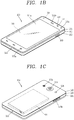
- FIG. 1A is a block diagram of a mobile terminal in accordance with the present invention
- FIGS. 1B and 1C are conceptual views of one example of the mobile terminal, viewed from different directions.
- the mobile terminal 100 may include components, such as a wireless communication unit 110, an input unit 120, a sensing unit 140, an output unit 150, an interface unit 160, a memory 170, a controller 180, a power supply unit 190 and the like.
- FIG. 1A illustrates the mobile terminal having various components, but implementing all of the illustrated components is not a requirement. Greater or fewer components may alternatively be implemented.
- the wireless communication unit 110 may typically include one or more modules which permit wireless communications between the mobile terminal 100 and a wireless communication system, between the mobile terminal 100 and another mobile terminal 100, or between the mobile terminal 100 and a network within which another mobile terminal 100 (or an external server) is located.
- the wireless communication unit 110 may include at least one of a broadcast receiving module 111, a mobile communication module 112, a wireless Internet module 113, a short-range communication module 114, a location information module 115 and the like.
- the input unit 120 may include a camera 121 for inputting an image signal, a microphone 122 or an audio input module for inputting an audio signal, or a user input unit 123 (for example, a touch key, a push key (or a mechanical key), etc.) for allowing a user to input information. Audio data or image data collected by the input unit 120 may be analyzed and processed by a user's control command.
- the sensing unit 140 may include at least one sensor which senses at least one of internal information of the mobile terminal, a surrounding environment of the mobile terminal and user information.
- the sensing unit 140 may include a proximity sensor 141, an illumination sensor 142, a touch sensor, an acceleration sensor, a magnetic sensor, a G-sensor, a gyroscope sensor, a motion sensor, an RGB sensor, an infrared (IR) sensor, a finger scan sensor, a ultrasonic sensor, an optical sensor (for example, refer to the camera 121), a microphone 122, a battery gage, an environment sensor (for example, a barometer, a hygrometer, a thermometer, a radiation detection sensor, a thermal sensor, a gas sensor, etc.), and a chemical sensor (for example, an electronic nose, a health care sensor, a biometric sensor, etc.).
- the mobile terminal disclosed herein may utilize information in such a manner of combining information sensed by at least two sensors of those sensors.
- the output unit 150 may be configured to output an audio signal, a video signal or a tactile signal.
- the output unit 150 may include a display unit 151, an audio output module 152, a haptic module 153, an optical output module 154 and the like.
- the display unit 151 may have an inter-layered structure or an integrated structure with a touch sensor so as to implement a touch screen.
- the touch screen may provide an output interface between the mobile terminal 100 and a user, as well as functioning as the user input unit 123 which provides an input interface between the mobile terminal 100 and the user.
- the interface unit 160 may serve as an interface with various types of external devices connected with the mobile terminal 100.
- the interface unit 160 may include wired or wireless headset ports, external power supply ports, wired or wireless data ports, memory card ports, ports for connecting a device having an identification module, audio input/output (I/O) ports, video I/O ports, earphone ports, or the like.
- the mobile terminal 100 may execute an appropriate control associated with a connected external device, in response to the external device being connected to the interface unit 160.
- the memory 170 may store a plurality of application programs (or applications) executed in the mobile terminal 100, data for operations of the mobile terminal 100, instruction words, and the like. At least some of those application programs may be downloaded from an external server via wireless communication. Some others of those application programs may be installed within the mobile terminal 100 at the time of being shipped for basic functions of the mobile terminal 100 (for example, receiving a call, placing a call, receiving a message, sending a message, etc.). Further, the application programs may be stored in the memory 170, installed in the mobile terminal 100, and executed by the controller 180 to perform an operation (or a function) of the mobile terminal 100.
- the controller 180 can typically control an overall operation of the mobile terminal 100 in addition to the operations associated with the application programs.
- the controller 180 can provide or process information or functions appropriate for a user by processing signals, data, information and the like, which are input or output by the aforementioned components, or activating the application programs stored in the memory 170.
- the controller 180 can control at least part of the components illustrated in FIG. 1 , in order to drive the application programs stored in the memory 170. In addition, the controller 180 can drive the application programs by combining at least two of the components included in the mobile terminal 100 for operation.
- the power supply unit 190 may receive external power or internal power and supply appropriate power required for operating respective elements and components included in the mobile terminal 100 under the control of the controller 180.
- the power supply unit 190 may include a battery, and the battery may be an embedded battery or a replaceable battery.
- the mobile terminal 100 disclosed herein may be provided with a bar-type terminal body.
- the present invention is not limited to this, but also may be applicable to various structures such as watch type, clip type, glasses type or folder type, flip type, slide type, swing type, swivel type, or the like, in which two and more bodies are combined with each other in a relatively movable manner.
- the mobile terminal 100 may include a case (casing, housing, cover, etc.) forming the appearance of the terminal.
- the case may be divided into a front case 101 and a rear case 102.
- Various electronic components may be incorporated into a space formed between the front case 101 and the rear case 102.
- At least one middle case may be additionally disposed between the front case 101 and the rear case 102.
- a display unit 151 may be disposed on a front surface of the terminal body to output information. As illustrated, a window 151a of the display unit 151 may be mounted to the front case 101 so as to form the front surface of the terminal body together with the front case 101.
- electronic components may also be mounted to the rear case 102.
- Examples of those electronic components mounted to the rear case 102 may include a detachable battery, an identification module, a memory card and the like.
- a rear cover 103 for covering the electronic components mounted may be detachably coupled to the rear case 102. Therefore, when the rear cover 103 is detached from the rear case 102, the electronic components mounted to the rear case 102 may be externally exposed.
- the rear cover 103 when the rear cover 103 is coupled to the rear case 102, a side surface of the rear case 102 may be partially exposed. In some cases, upon the coupling, the rear case 102 may also be completely shielded by the rear cover 103. Further, the rear cover 103 may include an opening for externally exposing a camera 121b or an audio output module 152b.
- the cases 101, 102, 103 may be formed by injection-molding synthetic resin or may be formed of a metal, for example, stainless steel (STS), titanium (Ti), or the like. Unlike the example which the plurality of cases form an inner space for accommodating such various components, the mobile terminal 100 may be configured such that one case forms the inner space. In this example, a mobile terminal 100 having a uni-body formed so synthetic resin or metal extends from a side surface to a rear surface may also be implemented.
- the mobile terminal 100 may include a waterproofing unit for preventing an introduction of water into the terminal body.
- the waterproofing unit may include a waterproofing member which is located between the window 151a and the front case 101, between the front case 101 and the rear case 102, or between the rear case 102 and the rear cover 103, to hermetically seal an inner space when those cases are coupled.
- the mobile terminal 100 may include a display unit 151, first and second audio output modules 152a and 152b, a proximity sensor 141, an illumination sensor 142, an optical output module 154, first and second cameras 121a and 121b, first and second manipulation units 123a and 123b, a microphone 122, an interface unit 160 and the like.
- the display unit 151, the first audio output module 152a, the proximity sensor 141, the illumination sensor 142, the optical output module 154, the first camera 121a and the first manipulation unit 123a are disposed on the front surface of the terminal body
- the second manipulation unit 123b, the microphone 122 and the interface unit 160 are disposed on a side surface of the terminal body
- the second audio output module 152b and the second camera 121b are disposed on a rear surface of the terminal body, with reference to FIGS. 1B and 1C .
- the first manipulation unit 123a may not be disposed on the front surface of the terminal body, and the second audio output module 152b may be disposed on the side surface other than the rear surface of the terminal body.
- the display unit 151 may output information processed in the mobile terminal 100.
- the display unit 151 may display execution screen information of an application program driven in the mobile terminal 100 or user interface (UI) and graphic user interface (GUI) information in response to the execution screen information.
- UI user interface
- GUI graphic user interface
- the display unit 151 may include at least one of a liquid crystal display (LCD), a thin film transistor-liquid crystal display (TFT-LCD), an organic light emitting diode (OLED), a flexible display, a 3-dimensional (3D) display, and an e-ink display.
- the display unit 151 may be implemented in two or more in number according to a configured aspect of the mobile terminal 100. For instance, a plurality of the display units 151 may be arranged on one surface to be spaced apart from or integrated with each other, or may be arranged on different surfaces.
- the display unit 151 may include a touch sensor which senses a touch onto the display unit so as to receive a control command in a touching manner.
- the touch sensor may be configured to sense this touch and the controller 180 can generate a control command corresponding to the touch.
- the content which is input in the touching manner may be a text or numerical value, or a menu item which can be indicated or designated in various modes.
- the touch sensor may be configured in a form of film having a touch pattern.
- the touch sensor may be a metal wire, which is disposed between the window 151a and a display on a rear surface of the window 151a or patterned directly on the rear surface of the window 151a.
- the touch sensor may be integrally formed with the display.
- the touch sensor may be disposed on a substrate of the display or within the display.
- the display unit 151 may form a touch screen together with the touch sensor.
- the touch screen may serve as the user input unit 123 (see FIG. 1A ). Therefore, the touch screen may replace at least some of functions of the first manipulation unit 123a.
- the first audio output module 152a may be implemented in the form of a receiver for transferring voice sounds to the user's ear or a loud speaker for outputting various alarm sounds or multimedia reproduction sounds.
- the window 151a of the display unit 151 may include a sound hole for emitting sounds generated from the first audio output module 152a.
- the present invention may not be limited to this. It may also be configured such that the sounds are released along an assembly gap between the structural bodies (for example, a gap between the window 151a and the front case 101). In this instance, a hole independently formed to output audio sounds may not be seen or hidden in terms of appearance, thereby further simplifying the appearance of the mobile terminal 100.
- the optical output module 154 may output light for indicating an event generation. Examples of the event generated in the mobile terminal 100 may include a message reception, a call signal reception, a missed call, an alarm, a schedule notice, an email reception, information reception through an application, and the like. When a user's event checking is sensed, the controller may control the optical output unit 154 to stop the output of the light.
- the first camera 121a may process video frames such as still or moving images obtained by the image sensor in a video call mode or a capture mode. The processed video frames may be displayed on the display unit 151 or stored in the memory 170.
- the first and second manipulation units 123a and 123b are examples of the user input unit 123, which may be manipulated by a user to input a command for controlling the operation of the mobile terminal 100.
- the first and second manipulation units 123a and 123b may also be commonly referred to as a manipulating portion, and may employ any method if it is a tactile manner allowing the user to perform manipulation with a tactile feeling such as touch, push, scroll or the like.
- the drawings illustrate the first manipulation unit 123a is a touch key, but the present invention may not be necessarily limited to this.
- the first manipulation unit 123a may be configured with a mechanical key, or a combination of a touch key and a push key.
- the content received by the first and second manipulation units 123a and 123b may be set in various ways.
- the first manipulation unit 123a may be used by the user to input a command such as menu, home key, cancel, search, or the like
- the second manipulation unit 123b may be used by the user to input a command, such as controlling a volume level being output from the first or second audio output module 152a or 152b, switching into a touch recognition mode of the display unit 151, or the like.
- a rear input unit may be disposed on the rear surface of the terminal body.
- the rear input unit may be manipulated by a user to input a command for controlling an operation of the mobile terminal 100.
- the content input may be set in various ways.
- the rear input unit may be used by the user to input a command, such as power on/off, start, end, scroll or the like, controlling a volume level being output from the first or second audio output module 152a or 152b, switching into a touch recognition mode of the display unit 151, or the like.
- the rear input unit may be implemented into a form allowing a touch input, a push input or a combination thereof.
- the rear input unit may be disposed to overlap the display unit 151 of the front surface in a thickness direction of the terminal body.
- the rear input unit may be disposed on an upper end portion of the rear surface of the terminal body such that a user can easily manipulate it using a forefinger when the user grabs the terminal body with one hand.
- the present invention may not be limited to this, and the position of the rear input unit may be changeable.
- a new user interface may be implemented using the rear input unit.
- the aforementioned touch screen or the rear input unit may substitute for at least part of functions of the first manipulation unit 123a located on the front surface of the terminal body. Accordingly, when the first manipulation unit 123a is not disposed on the front surface of the terminal body, the display unit 151 may be implemented to have a larger screen.
- the mobile terminal 100 may include a finger scan sensor which scans a user's fingerprint.
- the controller may use fingerprint information sensed by the finger scan sensor as an authentication means.
- the finger scan sensor may be installed in the display unit 151 or the user input unit 123.
- the microphone 122 may be formed to receive the user's voice, other sounds, and the like.
- the microphone 122 may be provided at a plurality of places, and configured to receive stereo sounds.
- the interface unit 160 may serve as a path allowing the mobile terminal 100 to exchange data with external devices.
- the interface unit 160 may be at least one of a connection terminal for connecting to another device (for example, an earphone, an external speaker, or the like), a port for near field communication (for example, an Infrared Data Association (IrDA) port, a BluetoothTM port, a wireless LAN port, and the like), or a power supply terminal for supplying power to the mobile terminal 100.
- the interface unit 160 may be implemented in the form of a socket for accommodating an external card, such as Subscriber Identification Module (SIM), User Identity Module (UIM), or a memory card for information storage.
- SIM Subscriber Identification Module
- UIM User Identity Module
- the second camera 121b may be further mounted to the rear surface of the terminal body.
- the second camera 121b may have an image capturing direction, which is substantially opposite to the direction of the first camera unit 121a.
- the second camera 121b may include a plurality of lenses arranged along at least one line.
- the plurality of lenses may also be arranged in a matrix configuration.
- the cameras may be referred to as an 'array camera.' When the second camera 121b is implemented as the array camera, images may be captured in various manners using the plurality of lenses and images with better qualities may be obtained.
- a flash 124 may be disposed adjacent to the second camera 121b. When an image of a subject is captured with the camera 121b, the flash 124 may illuminate the subject.
- the second audio output module 152b may further be disposed on the terminal body.
- the second audio output module 152b may implement stereophonic sound functions in conjunction with the first audio output module 152a (refer to FIG. 1A ), and may be also used for implementing a speaker phone mode for call communication.
- At least one antenna for wireless communication may be disposed on the terminal body.
- the antenna may be installed in the terminal body or formed on the case.
- an antenna which configures a part of the broadcast receiving module 111 may be retractable into the terminal body.
- an antenna may be formed in a form of film to be attached onto an inner surface of the rear cover 103 or a case including a conductive material may serve as an antenna.
- a power supply unit 190 for supplying power to the mobile terminal 100 may be disposed on the terminal body.
- the power supply unit 190 may include a batter 191 which is mounted in the terminal body or detachably coupled to an outside of the terminal body.
- the battery 191 may receive power via a power source cable connected to the interface unit 160. Also, the battery 191 may be (re)chargeable in a wireless manner using a wireless charger.
- the wireless charging may be implemented by magnetic induction or electromagnetic resonance.
- the drawing illustrates that the rear cover 103 is coupled to the rear case 102 for shielding the battery 191, so as to prevent separation of the battery 191 and protect the battery 191 from an external impact or foreign materials.
- the rear case 103 may be detachably coupled to the rear case 102.
- An accessory for protecting an appearance or assisting or extending the functions of the mobile terminal 100 may further be provided on the mobile terminal 100.
- a cover or pouch for covering or accommodating at least one surface of the mobile terminal 100 may be provided.
- the cover or pouch may cooperate with the display unit 151 to extend the function of the mobile terminal 100.
- Another example of the accessory may be a touch pen for assisting or extending a touch input onto a touch screen.
- the controller 180 of a mobile terminal capable of including at least one of the foregoing constituent elements may switch a lock state of the pre-registered external device to a release state when a plurality of touch inputs applied to the display unit 151 correspond to preset criteria when the display unit 151 is deactivated. Subsequently, the controller 180 can activate a predetermined region on the display unit 151, and then control the display operation to display the screen of the external device corresponding to the release state.
- the state of the display unit 151 being “deactivated” denotes a state in which lighting for illuminating the display unit 151 provided therewithin is in an "off” state. Furthermore, “activating" one region of the display unit 151 denotes a state in which lighting for illuminating one region of the display unit 151 provided therewithin becomes an "on” state.
- the external device is a concept containing all other terminals linked to the mobile terminal 100.
- the example of the external device may include navigators, slate PCs, tablet PCs, ultra books, wearable devices (for example, smart watches, smart glasses, head mounted displays (HMDs)), BluetoothTM head sets and the like.
- a control command corresponding to the connection or access may be transmitted at the same time.
- the foregoing "lock state” of the external device is a state in which a user's control command input to applications contained in the external device linked to the mobile terminal 100 is restricted.
- the display unit of the external device may be in an inactive state or active state. In the latter case, a lock screen corresponding to the lock state may be displayed on a screen provided on the external device.
- a function and the operations of the applications that have been operated prior to implementing the lock state may be continuously performed.
- a plurality of touch inputs corresponding to e-preset criteria denote a pattern in which a tap hitting the body is sensed when the display unit 151 is deactivated, and a user's operation pattern formed by sequentially connecting the sensed tap positions matches a preset pattern registered to release the release state.
- a plurality of touch inputs corresponding to preset criteria denotes a case where a touch is performed in a predetermined region, and then a consecutive touch followed within a preset period of time is applied to the predetermined region.
- the mobile terminal 100 may use only either one of an acceleration sensor and a touch sensor, sequentially use the acceleration sensor and touch sensor, or concurrently use the acceleration sensor and touch sensor.
- the "release state" of the external device is a state in which a user's control command input to an external device linked to the mobile terminal 100 is not restricted. Accordingly, when the screen of the external device corresponding to the release state is displayed in one region of the display unit 151, the function and applications of the external device may be activated or deactivated according to a control command entered through the touch sensor or user input unit 130 provided in one region of the display unit 151.
- the foregoing "lock state" may be performed again when a user's input is not sensed for a preset period of time when the screen of the external device corresponding to the release state is displayed in one region of the display unit 151.
- the preset period of time may be changed by the user's setting.
- the mobile terminal 100 may apply a plurality of touch inputs to the display unit 151 in an inactive state, thereby switching the linked external device to an active state or switching a lock state to a release state. Accordingly, the user may omit a complicated process for taking out another terminal to be used to turn on the display unit, and entering a password using a virtual keypad or the like to release a lock state.
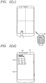
- FIGS. 2(a) to 2(d) are representative conceptual views illustrating an operation implemented according to an embodiment of the present invention. As illustrated in FIGS. 2(a) and 2(b) , the display unit 151 is partitioned into a plurality of virtual regions (A, B, C, D) when the display unit 151 is deactivated.
- the plurality of regions are illustrated as an example in which the entire display unit 151 is partitioned into four regions (A, B, C, D), but the present invention is not limited to this.
- the plurality of regions may be partitioned with a number of regions less than or greater than the four regions of the display unit 151, and may be generated only in one region of the display unit 151 (a region corresponding to a user's left/right hand when holding the terminal with his or her one hand).
- At least one of the partitioned regions may be used as an input region capable of controlling at least one external device linked to the mobile terminal 100.
- an external device corresponding to the user's setting may be pre-registered in at least one of the partitioned regions (A, B, C, D).
- the figures include numerals indicating a virtual line for partitioning a region and the plurality of regions for the sake of convenience of explanation.
- the sensing unit 140 can sense a plurality of touch inputs applied to at least one of the plurality of regions when the display unit 151 partitioned into a plurality of virtual regions (A, B, C, D) is deactivated. Subsequently, a result sensed by the sensing unit 140 is transferred to the controller 180.
- the sensing unit 140 can sense a location to which the touch input is applied, an input interval thereof, and the like, and sense which one of the partitioned virtual regions to which the location is applied.
- the mobile terminal 100 may use only either one of an acceleration sensor and a touch sensor, sequentially use the acceleration sensor and touch sensor, or concurrently use the acceleration sensor and touch sensor.
- the controller 180 can determine whether or not a plurality of touch input sensed through the sensing unit 140 corresponds to preset criteria.
- the plurality of touch inputs corresponding to preset criteria denotes when a plurality of taps sensed when the display unit 151 is deactivated is consecutively applied within a preset limited period of time, and a user's operation pattern formed by sequentially connecting the sensed tap positions satisfies a first condition matching a pre-registered pattern.
- the plurality of touch inputs corresponding to preset criteria denotes when a plurality of taps sensed in a specific region when the display unit 151 is deactivated satisfy a second condition in which they are consecutively applied within a preset limited period of time.
- a plurality of touch inputs satisfying the second condition as described above is called a "knock-knock" (or knock-on) being sensed for the purpose of controlling a specific external device.
- FIG. 2(c) illustrates when a second condition in which a plurality of taps sensed in region "C" are consecutively applied within a preset limited period of time.
- the controller 180 can recognize a pre-registered external device corresponding to a region to which a plurality of touch inputs are applied among the plurality of regions. For example, a "watch type terminal 300" corresponding to a specific region ("C") to which a plurality of traffic indication response message are applied can be recognized in FIG. 2(c) .
- the controller 180 performs a control operation corresponding to a touch input with respect to the recognized external device.
- a connection or access between the mobile terminal 100 and the recognized external device may be performed in advance or performed when a touch input satisfying the foregoing condition (first or second condition) is applied thereto (in other words, a control command for connecting or accessing to the recognized external device may be transmitted along with a control command corresponding to the control operation).
- the controller 180 transfers a control command for switching a recognized external device to an "on” state to the recognized external device. Accordingly, as illustrated in FIG. 2(c) , the display of the watch type terminal 300 corresponding to the region ("C") is turned into an "on” state.
- a lock state of the watch type terminal 300 is switched to a release state, and a screen corresponding to the release state is displayed on the display of the watch type terminal 300.
- a lock screen corresponding to the lock state is displayed on the display of the watch type terminal 300 as illustrated in FIG. 2(c) .
- the controller 180 switches one region of the display unit 151, namely, an upper left portion thereof, to an active state, and receives screen information from the external device that has been switched to an "on" state to display it on the activated one region as illustrated in FIG. 2(d) .
- the lock screen 301 of the watch type terminal 300 is displayed in the first region 251a.
- another region 251b out of said one region of the display unit 151 may continuously maintain an inactive state.
- the user may apply a touch for entering a preset pattern to the lock screen 301 in the first region 251a illustrated in FIG. 2(d) to switch a lock state of the external device to a release state.
- the user may control the display operation of the external device using the display unit 151 of the mobile terminal 100.
- a pattern entered to the lock screen 301 matches a preset pattern, the lock state of the external device is released, and a screen corresponding to the release is displayed on the screen of the first region 251a and the external device.
- a predetermined key provided in the mobile terminal 100 is pushed to the mobile terminal 100 to switch the entire display unit 151 to an active state, and display a lock screen corresponding to the lock state or a home screen page on the display unit 151, the screen of the external device that has been displayed in the first region 251a may disappear.
- the lock state of another pre-registered terminal may be released using a plurality of taps applied to the display unit 151 when the display unit 151 of the mobile terminal 100 is deactivated. According to this, a complicated process for taking out an external device to turn on the display unit, and then entering a password using a virtual keypad or the like to release the lock state of the external device linked to the mobile terminal 100 is omitted.
- the present invention will be described on the assumption that the display unit 151 of the mobile terminal 100 according to an embodiment of the present invention is provided with a touch sensor configured to sense a touch input, and initially in an inactive state.
- the "state that the display unit 151 is deactivated” denotes a state in which lighting for illuminating the display unit 151 provided therewithin is in an "off" state as described above.
- the sensing unit 140 of the mobile terminal 100 can sense a plurality of touch inputs applied to at least one region of the display unit 151 (S310).
- a plurality of touch inputs may denotes taps consecutively hitting one region of the display unit 151 within a preset limited period of time.
- the controller 180 determines whether or not the plurality of sensed touch inputs corresponds to preset criteria (S320).
- the plurality of touch inputs corresponding to preset criteria denotes when a tap hitting the body is sensed in a specific region when the display unit 151 is deactivated, and a user's operation pattern formed by sequentially connecting the sensed tap positions satisfies a first condition matching a preset pattern registered to release the lock state of the external device corresponding to the specific region.
- the display unit 151 may be partitioned into a plurality of virtual regions in an inactive state.
- the virtual regions may be formed with an upper left, an upper right, a lower left and a lower right quadrants in which the display unit 151 is partitioned by the x and y axes based on a central position as illustrated in FIG. 2(b) .
- the present invention is not limited to this, and the plurality of virtual regions may be formed in various ways such as dividing the display unit 151 into an upper and a lower half portions or an upper, a middle and a lower one-third portions, and the like.
- the external device corresponding to a region to which the touch inputs are applied denotes another terminal matched through the user setting to control the another terminal using a specific region.
- the controller 180 can recognize another terminal for example, glass type terminal, registered to match the relevant region.
- the external device corresponding to a region to which the touch inputs are applied may be changed by the user setting.
- the controller 180 transfers a first control command for connecting to a recognized external device to the recognized external device through the wireless communication unit 110.
- the controller 180 Upon receiving a response to the first control command from the external device, the controller 180 transfers a second control command for switching a lock state of the connected external device to a release state to the external device through the wireless communication unit 110.
- the transfer of the first control command may be omitted.
- the controller may display a feedback corresponding to the connection failure (for example, notification of a connection failure and cause of a connection failure) in one region of the display unit 151 or notify it to the user through the audio output unit 152.
- the controller may output a feedback indicating switching to the release state (for example, vibration, sound (e.g., "beep sound” or "lock is released”), LED effect) to the mobile terminal 100 and/or external device.
- the plurality of touch inputs corresponding to preset criteria denotes when a touch is performed in a predetermined region, and then a consecutive touch followed within a preset period of time is applied to the predetermined region, namely, it satisfies a second condition in which a "knock-on" is sensed in a specific region.
- the controller 180 can recognize an external device corresponding to a region too which a "knock-on” is applied, and switch the recognized external device to an active state, namely, a state in which the display is activated.
- a lock screen formed to enter a password for example, is displayed on the display of the external device switched to an active state.
- the controller 180 can switch one region of the display unit 151 to an active state (S340).
- said one region (“first region”) may be previously determined as a default value or changed by a user setting.
- the first region may be defined as a region corresponding to a region to which a plurality of touch inputs is applied.
- the first region may be defined as a form of being completely identical to a region to which a plurality of touch inputs are applied among virtual regions partitioned on the display unit 151, or contained in the region, or in which part thereof is overlapped with the region and the other portion thereof is out of the region.
- the controller 180 can control another region ("second region") out of one region of the display unit 151 to continuously maintain an inactive state. Subsequently, the controller 180 receives screen information corresponding to the release state through the wireless communication unit 110 from the external device to display it in the active region (S350).
- a screen displayed in the release state may be at least one of a home screen, an execution screen of an application, a menu screen, and a screen corresponding to an event occurred on the terminal.
- the screen When the screen is a home screen, it may include at least one object.
- the object may be an icon or widget of an application installed on an external device.
- the screen may be a screen corresponding to screen information that has been most recently displayed on the display prior to executing the lock state of the external device.
- the controller 180 can change at least one of the location and size of a first region displayed with screen information corresponding to the release state through a preset type of touch input. Further, when a plurality of touch inputs corresponding to preset criteria satisfy the foregoing second condition, screen information corresponding to an "on" state of the external device, namely, a lock screen of the external device, may be displayed in the active region. The user may perform an input having a preset pattern on the displayed lock screen to switch a lock state of the external device to a release state.
- the controller 180 can partition the foregoing plurality of virtual regions again based on the second region.
- the controller 180 can perform an operation mode to activate only either one of when a plurality of touch inputs applied to the display unit 151 in an inactive state correspond to first criteria and when they correspond to second criteria.
- the security can be enhanced when an operation mode is set to control the display operation of an external device only when corresponding to first criteria.
- an operation mode is set to control the display operation of an external device only when corresponding to first criteria.
- a "knock-on" is applied when the external device is a BluetoothTM headset
- a plurality of touch inputs with a preset operation pattern may be applied without immediately performing a "pairing” procedure, thereby preventing any use thereof by a third party during a theft of the external device.
- an operation mode is set to control the display operation of an external device only when corresponding to second criteria, it may be possible to access a desired external device to take a screen only by applying a "knock-on" to a specific region, thereby further enhancing user convenience.
- a plurality of touch inputs with a preset pattern may be applied to a specific region when the display unit 151 of the mobile terminal 100 is deactivated to release the lock state of the linked external device. Accordingly, the processes of taking out an external device to be used to activate the display unit, and then performing a specific pattern input on a lock screen displayed on the screen of the external device can be all omitted, thereby providing a convenient user environment.
- FIGS. 4(a) to 4(d) are conceptual views illustrating a method of controlling the screen of an external device using a touch input applied to the display unit as an example of the operation implemented according to an embodiment of the present invention.
- the controller 180 can recognize an external device corresponding to the specific region, and switch the recognized external device to an "on" state.
- the display of the external device is switched from an inactive state to an active state. Accordingly, a "lock screen" appears on the display of the external device.
- the controller 180 of the mobile terminal 100 can receive screen information displayed on the external device through the wireless communication unit 110 to display it in the first region (for example, predetermined region) of the display unit 151.
- a lock screen 401 for the connected external device is displayed in a predetermined region, for example, an upper left region 251a of the display unit 151.
- the inactive state of the other region 251b continuously maintains.
- a plurality of image objects capable of entering a pattern for releasing the lock state of the external device may be displayed on the lock screen.
- a pre-registered pattern using the plurality of image objects is entered in a lock screen displayed in the first region of the display unit 151 to release the lock state of the external device (for example, a touch start point and a touch end point for the plurality of image objects, and a path to connect them to each other match a pre-registered pattern)
- the controller 180 can switch the lock state of the external device to a release state.
- the controller 180 can change the display status and display range of the lock screen displayed in the first region based on a preset touch input. For such an example, the controller 180 can gradually change the size of an image corresponding to the screen information displayed in the first region in response to a touch started from one side of the first region being dragged in one direction (for example, a direction of being away from the first region). Next, the controller 180 can fix the image based on a position at which the touch is released.
- a lock screen 401" in which its size is changed in proportion to the dragged distance may be displayed.
- the second region 251b that has been in an inactive state may be gradually activated along the drag path (namely, increasing the size of the first region 251a), or switched to a state that the entire display unit 151 is activated.
- an image effect such as unfolding a rolled paper or an image effect such as stretching an elastic body like a rubber band may be applied to an image corresponding to the lock screen 401 according to the drag path.
- the user may perform a pattern input for releasing the lock state of the external device on a larger-sized screen.
- a preset pattern is entered to the lock screen 401" to switch the lock state of the external device to a release state as illustrated in FIG. 4(b)
- the release screen 402 corresponding to the release may be displayed again in the predetermined first region 251a as illustrated in FIG. 4(c) .
- a screen displayed in the release state may be at least one of a home screen, an execution screen of an application, a menu screen, and a screen corresponding to an event occurred on the external device, and various types of screens may be displayed according to the setting or user's selection.
- the controller 180 can stop displaying the release screen in the first region.
- the controller 180 can recognize that a control operation executed through a touch input applied to the display unit 151 is changed from a "first mode" for controlling the display operation of the external device to a "second mode” for controlling the display operation of the mobile terminal.
- a control operation executed through a touch input applied to the display unit 151 is changed from a "first mode” for controlling the display operation of the external device to a "second mode” for controlling the display operation of the mobile terminal.
- screen information displayed in the first region may be displayed in a floating window format.
- the operation mode may be determined by a type of touch input applied to a region out of the first region in FIG. 4(c) . For example, only screen information displayed in the first region disappears when a short touch is applied to the second region 251b, and it is changed to the second mode when a double short touch is applied to the second region 251b, and the screen information that has been previously displayed in the first region is displayed again when a double short touch is applied to the first region in the state of being switched to the second mode ( FIG. 4(d) ). Due to the operation mode, it may be possible to provide convenience capable of performing and checking the display operation of the mobile terminal 100 and external device on one screen.
- the entire display unit 151 of the mobile terminal 100 may be switched to an active state to display a lock screen, a home screen page or the like of the mobile terminal 100 other than the screen of the external device. Further, the foregoing series of processes of changing the display state and display range of a lock screen displayed in the first region based on a preset touch input may be applicable similarly to when a release screen is displayed in the first region.
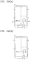
- FIGS. 5A(a) to 5A(d) and 5B(a) to 5B(c) are conceptual views illustrating a method of displaying guide information with respect to virtual regions on the display unit as an example of the operation implemented according to an embodiment of the present invention.
- the display unit 151 is partitioned into a plurality of virtual regions in an inactive state.
- a consecutive touch input namely, "knock-on”
- an external device corresponding to the region to which the touch input is applied can be recognized.
- a watch type terminal may be registered to match surface "A” and a glass type terminal may be registered to match surface "C" when the display unit 151 is deactivated. Accordingly, in order to turn on the status of a watch type terminal or switch it to a release state, a plurality of touch inputs should be performed on surface "A" and the user should recognize a device matching a location of the region in advance.
- the controller 180 can display guide information indicating an external device corresponding to a region corresponding to the touch gesture.
- the guide information may be a preset image, text or a user set image capable of identifying the external device.
- a "glass image” may correspond to this.
- the guide information may include a horizontal line 502b and a vertical line 501a crossing a central position of the display unit 151.
- the guide information may be displayed with a black-and-white or dotted line, and when the guide information is an object image, it may be shown in the form of displaying only an outside of the object.
- the controller 180 can display different guide information according to a time sequence based on touch gesture applied to the display unit 151. For example, as illustrated in FIG. 5A(b) , when a proximity touch gesture is sensed on the display unit 151 in an inactive state, lines 502b, 501a partitioning virtual regions are shown, and when the proximity touch gesture is maintained for a preset period of time in a specific region among them, an image of the external device corresponding to the relevant region ("C"), namely, a thumbnail image 502 of the glass type terminal, is displayed.
- C relevant region
- the controller partitions the relevant region into a plurality of sub-regions, and displays guide information (for example, horizontal and vertical lines 503b, 503a) illustrating the partitioned sub-regions.
- guide information for example, horizontal and vertical lines 503b, 503a
- the controller 180 recognizes the touch as a confirmation of an external device corresponding to the relevant region ("C"), thus not allowing it to be contained in the foregoing plurality of touch inputs.
- the controller 180 processes a touch corresponding to the touch down event and the foregoing plurality of touch inputs in a distinguished manner.
- a lock state of the glass type terminal is switched to a release state.
- the foregoing guide information may be also output along with voice guide or only with the voice guide. For example, when a users' finger (or stylus pen) comes close to region "C" in FIG. 5A(b) , a guide voice such as "Would you release the glass” may be output.
- the guide information may vary to correspond to the moved region.
- region "C” a specific region
- the guide information may vary to correspond to the moved region.
- new guide information namely, a BluetoothTM headset image 503 may be shown in region "D".
- the display of the guide information 503, 504 disappears.
- guide information when guide information is displayed on the display unit 151 with only a proximity touch gesture, the battery consumption increases, thus it may be possible to implement that guide information is displayed only while pressing a specific key (or subsequent to a starting gesture) or change whether or not to display guide information through the user's setting.
- the user may view guide information displayed on the display unit 151 and easily understand that an external device for releasing the lock state matches which region thereof, and a plurality of touch inputs are entered to which regions.
- FIGS. 6(a) to 6(d) are conceptual views illustrating a method of registering an external device in virtual regions on the display unit as an example of the operation implemented according to an embodiment of the present invention.
- different external devices may match virtual regions, respectively, partitioned on the display unit 151 in an inactive state.
- external devices corresponding to the plurality of partitioned regions may be set or changed by a user input.
- FIGS. 6(a) to 6(d) when entering a "knock-on setting mode", a plurality of regions are shown, and guide information (for example, "Please select a region") for guiding to select a "specific region” is displayed as illustrated in FIG. 6(a) .
- guide information 610a for example, "Please select a device” for guiding the selection of a "device” and a popup menu window 610b are displayed as illustrated in FIG. 6(b) .
- a plurality of selectable external devices for example, a headset, a watch, a glass, etc. linked to the mobile terminal 100 are displayed in a text format on the popup menu window 610b.
- the popup menu window 610b disappears, and an image 620 of the selected external device and an icon 630 for checking the selection are displayed in the selected region ("D") as illustrated in FIG. 6(c) .
- the controller 180 sets the "glass” to an external device matching region "D".
- the images of external devices matching each region may be displayed in the corresponding regions, respectively, thereby allowing the user to check them as illustrated in FIG. 6(d) .
- an operation pattern for switching the lock state of the external device to a release state is registered.
- the operation pattern is formed by taps hitting the terminal a plural number of times, and more specifically, formed by sequentially connecting the tap positions of the taps. For example, tap positions due to four taps may be set to an operation pattern for sequentially forming the vertices of alphabet capital letter "N".
- the controller 180 can partition the entire region of the display unit 151 into a plurality of regions, and allow the user to set an operation pattern using the partitioned regions. For example, when the set password is "3142", the controller 180 divides the display unit 151 based on the highest numeral ("4") among the entered numerals. For example, as illustrated in FIG. 5A(d) , the controller 180 can divide a specific region of the display unit 151 into four quadrants. Then, identification numbers may be given to the four quadrants sequentially from the upper left portion (for example, from a first quadrant to a fourth quadrant). Then, the controller 180 can set a first tap through a fourth tap applied to the third, the first, the fourth and the second quadrant to an operation pattern. Accordingly, an operation pattern forms the vertices of alphabet capital letter "N".
- a password for the mobile terminal 100 may be set to match a specific region, and a password setting for the external device and a password setting for the mobile terminal 100 may be processed in a distinguished manner.
- an input for selecting either one of a "body mode” and an "external device mode” may be performed prior to performing the foregoing step S310 in FIG. 3 .
- the input may be a gesture operation (for example, a starting gesture for covering the entire display unit 151 for a preset period of time using a palm) to perform the "external device mode".
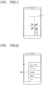
- FIGS. 7A(a) to 7A(d) and 7B(a) to 7B(d) are conceptual views illustrating a method of releasing a lock state of an external device using a touch input applied to the display unit as an example of the operation implemented according to an embodiment of the present invention.
- a plurality of virtual regions (A,B, C, D) on the display unit 151 in an inactive state may include a plurality of sub-regions, respectively. For example, sub-regions partitioned again into four quadrants may be generated within region "A".
- the user may perform taps in a sequence corresponding to a preset pattern in the plurality of sub-regions partitioned within a specific region ("C"), for example, taps in the sequence of 1,2,3,4 within the region ("C").
- the mobile terminal 100 may include a sensing unit for sensing a tap hitting the body when the display unit 151 is deactivated.
- the preset pattern may be defined by sequentially connecting a plurality of touch inputs applied to a specific region in a predetermined sequence.
- a plurality of touch inputs applied to region "C” may be connected according to a touched sequence. thereby recognizing an operation pattern forming each vertex of symbol " ".
- the controller 180 can switch a lock state of the external device corresponding to the selected specific region to a release state in response to a plurality of touch inputs sequentially applied according to a preset sequence (for example, 1,2,3,4) to at least one sub-region corresponding to a preset pattern among a plurality of sub-regions (for example, "a, b, c, d") contained in the selected specific region (for example, "C").
- a preset sequence for example, 1,2,3,4
- the controller 180 recognizes an external device, for example, watch type terminal 300, corresponding to region "C", and transmits a wireless signal for switching a lock state of the recognized watch type terminal 300 to a release state through the wireless communication unit 110 as illustrated in FIG. 7A(c) . Then, as described above, a release screen 801 corresponding to the release state is received from the watch type terminal 300, and displayed in the first region 251a of the display unit 151. Unless a touch input is applied thereto for a preset period of time, the release screen 801 displayed in the first region 251a disappears from the display unit 151, and the first region 251a is switched to an inactive state again.
- an external device for example, watch type terminal 300, corresponding to region "C”
- a wireless signal for switching a lock state of the recognized watch type terminal 300 to a release state through the wireless communication unit 110 as illustrated in FIG. 7A(c) .
- a release screen 801 corresponding to the release state is received from the watch type terminal 300, and
- the first region 251a is not switched to an active state.
- the controller 180 can output voice guide indicating that the password does not match the preset password through the audio output unit 152.
- the recognized external device may be switched to an "on" state, namely, a state that the display is activated.
- At least one of the location and size of a plurality of partitioned regions on the display unit 151 may vary according to a touch position at which the plurality of touch inputs are sensed on the display unit 151.
- the mobile terminal 100 may set a touch region for recognizing an external device that performs the control and a touch region for switching a lock state of the recognized external device to a release state to be different from each other.
- a touch applied to a specific region ("D") among the virtual regions (A, B, C, D) when the display unit 151 is deactivated is recognized as a touch input for selecting an external device to be controlled.
- the touch input recognized herein is not contained in the plurality of touch inputs that have been described above or will be described later.
- the corresponding external device for example, "watch type terminal”
- the controller 180 can newly configure the initially partitioned virtual regions with virtual sub-regions for the plurality of touch inputs in association with the recognized external device.
- the sub-regions are partitioned with a large size out of the relevant region ("D"").
- the sub-regions of the region "D"" may be partitioned over the entire display unit 151 or partitioned in a predetermined region (for example, a central region of the display unit).
- the location or size disposed with virtual regions or virtual sub-regions may vary according to a user's location or posture. For example, when the user performs a plurality of touch inputs using one hand touch while holding the mobile terminal 100 with his or her left hand, the foregoing virtual regions and sub-regions within each region may be sequentially generated within a region with which the user's left thumb is brought into contact. Similarly, when the user performs a plurality of touch inputs using one hand touch while holding the mobile terminal 100 with his or her right hand, the foregoing virtual regions and sub-regions within each region may be sequentially generated within a region with which the user's right thumb is brought into contact. Accordingly, the user can perform a connection to an external device and a release of the lock state of the external device, thereby enhancing the user's convenience.
- a touch sensor should be active even when the display unit 151 is deactivated, there by recognizing the touch inputs.
- the sensing unit 140 may sense a "knock-on" in different ways according to whether or not the display unit 151 is activated.
- the touch sensor may execute an active mode for maintaining an active state (including a case of switching between an active state and an inactive state for a short period of time to the extent to be seen as being substantially activated.
- an active mode for maintaining an active state (including a case of switching between an active state and an inactive state for a short period of time to the extent to be seen as being substantially activated.
- a doze mode in which an active state and an inactive state are switched for a preset period of time may be performed to reduce battery consumption.
- the touch sensor may execute the doze mode to be active for each preset period of time.
- the speed for sensing a "knock-on" applied to the display unit 151 increases, but accordingly the power consumed by the sensing unit 140 increases.
- the power consumed by the sensing unit 140 decreases, but accordingly the speed for sensing a touch applied to the display unit 151 decreases.
- the preset period of time may be set to be fast to the extent that the sensing speed cannot not be recognized by the user when sensing a touch applied to the display unit 151 as well as to enhance the efficiency of power consumption.
- the preset period of time may be set such a manner that the touch sensor is activated 30 times per second (30 Hz). It may correspond to a minimum current level capable of recognizing a touch when the display unit 151 is deactivated.
- the touch sensor may execute a doze mode when the display unit 151 is deactivated, but execute the active mode when a first tap is applied to the display unit 151.
- the touch sensor may execute an active mode to more accurately sense a tap to be applied afterwards.
- the touch sensor may be set to be active approximately 120 times per second (120 Hz).
- the touch sensor may switch the active mode to a doze mode. It is because a user's unintentional tap has occurred to prevent a malfunction in the terminal from being generated. Furthermore, according to an embodiment of the present invention, only when at least two or more (or a plurality of) taps are consecutively applied within at least a limited period of time, the controller 180 can determine whether or not an operation pattern for defining a release command is applied.
- a plurality of touch inputs applied to the display unit 151 in an inactive state satisfying the foregoing first condition denotes applying a "knock-on" in which the second tap is sensed within a limited period of time from a time point at which at least the first tap had been sensed to a specific region (a region matching an external device desired to control the operation) among the virtual regions partitioned on the display unit 151.
- a plurality of touch inputs applied to the display unit 151 in an inactive state satisfying the foregoing first condition denotes sensing a "knock-on" in a specific region (a region matching an external device desired to control the operation) among the virtual regions partitioned on the display unit 151, and then applying taps to the virtual sub-regions in a sequence matching a preset operation pattern.
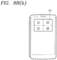
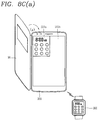
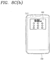
- FIGS. 8A(a), 8A(b) , 8B(a) , 8B(b) , 8C(a) , and 8C(b) are conceptual views illustrating a method of changing a region to which a touch input is applied according to an open or closed state due to a cover when the cover is contained in a frame of the mobile terminal 100 as an example of the operation implemented according to an embodiment of the present invention.
- a cover 90 may include a first member and a second member disposed at a front and a rear surface of the terminal body. Furthermore, the cover 90 may further include a connecting portion for connecting the first and the second member. The connecting portion may be formed to cover a lateral surface of the mobile terminal. Furthermore, a hole 90a having a predetermined shape (for example, a rectangle) is formed to always expose a specific region of the display unit 151 on a front surface of the cover 90.
- first and the second member may be formed with a flexible material.
- the first and the second member, and the connecting portion may include at least one of polyurethane, PVC, bakelite, and cardboard.
- an outside line forming the hole 90a may be formed with a different material from that of the first member or the first member may be coated in a thicker manner than the surrounding thereof.
- the mobile terminal 100 mounted with the cover 90 can control the display unit 151 to be activated by the movement of the first member.
- the cover 90 may include a magnet formed on the second member, and a sensor unit formed in one region of the mobile terminal body corresponding to the magnet in a closed state of the mobile terminal 100 to sense a magnetic change of the movement of the magnet.
- they when including a plurality of magnets, they may be disposed to be separated from each other, and In this instance, the magnets may be disposed to be adjacent to each other in the second member or at least one of them may be disposed in one region of the first member.
- the controller may sense switching from either one of a closed state and an open state of the cover 90 to the other one state based on a magnetic change sensed by the hole sensor according to the movement of the first member (moving toward the bottom surface).
- An “open state” of the cover 90 denotes a state in which the entire display unit 151 is exposed as illustrated in FIG. 8A(a)
- a “closed state” of the cover 90 denotes a state in which only a portion corresponding to the hole 90a of the cover 90 is exposed on the display unit 151 as illustrated in FIG. 8A(b) .
- the controller 180 can control the active state of the display unit 151 in a different manner and/or control the display unit 151 to display different screen information.
- the virtual regions are partitioned based on the entire display unit 151 in the "open state" of the cover 90, and the virtual regions are partitioned based on only a portion corresponding to the hole 90a of the cover 90 on the display unit 151 in the "closed state” of the cover 90.
- the controller 180 can control at least one of the size and location of a plurality of virtual regions to be varied in response to the cover being switched from either one of the closed state and open state to the other one.
- virtual regions are partitioned on an exposed portion (hereinafter, referred to as a "window") corresponding to the hole 90a of the cover 90 on the display unit 151 in a "closed state" of the cover 90.
- a window an exposed portion corresponding to the hole 90a of the cover 90 on the display unit 151 in a "closed state” of the cover 90.
- virtual regions partitioned on the window are changed to sub-regions (a, b, c, d) 902 for the selected specific region (2).
- the user first applies a "knock-on" to a specific region on the window to select an external device to be controlled, and then perform a plurality of touch inputs matching a preset operation pattern again within the window.
- the controller may control at least one of the size and location of the first region in which a screen displayed on the external device is displayed to be varied in response to the cover being switched from either one of the closed state and open state to the other one.
- the controller 180 controls the activation of the display unit 151 according to the varied size and location of the first region.
- FIGS. 9(a) to 9(c) are conceptual views illustrating a method of releasing a lock state of the external device using another touch scheme applied to the display unit as an example of the operation implemented according to an embodiment of the present invention.
- the external device is matched and registered to a line of the specific pattern without matching the specific region to the external device.
- the lines of the specific pattern may be any line that can be connected with one brush drawing.
- a specific alphabet, a specific symbol, a numeral, or the like may be a line of the specific pattern.
- the line of the specific pattern may be previously determined as a default (for example, a line with a specific pattern can be previously determined for each wearable device linked to the mobile terminal 100) or changed by a user setting.
- the controller 180 can recognize an external device corresponding to the touch line. Subsequently, when a plurality of touch inputs consecutively applied to the display unit 151 correspond to the foregoing criteria (first criteria), the lock state of the recognized external device may be switched to a lock state.
- FIGS. 9(a) to 9(c) when alphabet "G" is matched and registered to a glass type terminal in the mobile terminal 100, a user may draw alphabet “G” using his or her hand or stylus pen and then apply an "knock-on” when the display unit 151 is deactivated as illustrated in FIG. 9(a) and 9(b) .
- the controller 180 accesses a glass type terminal to receive screen information displayed on the glass type terminal, and display screen information 1001, for example, a lock screen, in the first region of the display unit 151.
- the mobile terminal 100 is also switched to an "on” state by the "knock-on” applied to the display unit 151 to display preset screen information (for example, a lock screen, a home screen page, etc.).
- the screen information of a glass type terminal displayed in the first region may be allowed to disappear when a preset period of time has passed or when touching one position of a region out of the first region. Accordingly, the user may perform the control of the mobile terminal 100 subsequent to the control of the glass type terminal.
- a lock state of the relevant external device may be switched to a release state.
- the lock state of the corresponding external device may be switched to a release state only by drawing a line of the specific pattern and applying a "knock-on" to the display unit 151 in an inactive state.
- the controller 180 can switch a lock state of the external device corresponding to the touch line to a release state in response to a plurality of touch inputs being sequentially applied in a consecutive manner according to a predetermined sequence to at least one region corresponding to a preset pattern among the plurality of regions (for example, the display unit 151 can be partitioned into four quadrants using a central position thereof as an intersection). Then, the controller can switch the first region of the display unit 151 to an active state to display screen information corresponding to the release state.
- FIGS. 10(a) to 10(d) are conceptual views illustrating a method of controlling "a plurality of external device screens" on one screen using a touch input applied to the display unit as an example of the operation implemented according to an embodiment of the present invention.
- the corresponding external device may be matched and registered to each of the partitioned virtual regions when the display unit 151 is deactivated.
- the user may want to control a plurality of external devices matching each region.
- the user when the user wants to release the lock state of the glass type terminal and watch type terminal using the display unit of the mobile terminal 100, is the user is inconvenienced because he or she has to take out each device and push a specific key and activate the screen and enter each pattern. Furthermore, even subsequent to releasing the lock state, the user is inconvenienced because screen has to be manipulated on a separate terminal.
- the controller 180 can sense a second touch line having a pre-registered shape being newly applied to a region out of the first region through the sensing unit 140 when first screen information corresponding to the release state of the external device is displayed in the first region of the display unit 151 as described above.
- the controller 180 can sense that a touch line having a preset pattern, for example, alphabet "W", applied to the second region 251b in an inactive state is drawn as illustrated in FIG. 10(b) .
- the controller recognizes a second external device (for example, watch type terminal) corresponding to the drawn touch line, and receives a lock screen from the second external device to display the received lock screen at a portion of the second region "B") as illustrated in FIG. 10(d) .
- a second external device for example, watch type terminal
- the controller switches a lock state of the external device corresponding to the applied second touch line to a release state in response to a plurality of touch inputs being sequentially applied according to a preset sequence to at least one region corresponding to a preset pattern among a plurality of virtual regions (for example, a plurality of virtual regions can be generated in region "B" in FIG. 10(d) .
- the controller 180 can activate a second region of the display unit 151 to display second screen information corresponding to the release state of the external device corresponding to the second touch line.
- the first and the second screen information displayed in each region are independently controlled, and synchronization with the corresponding external device is performed. For example, when a screen is changed on a glass type terminal, the first screen information is changed in a corresponding manner.
- the controller 180 can stop displaying the first and the second screen information.
- the entire display unit 151 may be switched to an active state, and the lock screen or preset screen (a screen that has been most recently displayed prior to being switched to a home screen page or inactive state) of the mobile terminal 100 may be displayed thereon.
- the operation of a plurality of registered devices may be controlled in a simple manner on one mobile terminal.
- a preset touch input for example, double short touch input
- the controller may control at least one of the first and the second screen information to be displayed again on the display unit 151.
- the first and the second screen information may be displayed when a double short touch input is applied within a first period of time
- the screen information for example, second screen information
- the screen information that has been displayed lately may be displayed when a double short touch input is applied within a second period of time after the first period of time has passed.
- a mobile terminal in accordance with an embodiment of the present invention and a control method thereof it may be possible to release a lock state of another pre-registered terminal using a plurality of taps applied when the display unit is deactivated. Due to this, the lock state of another terminal may be released using a simple method of hitting the display unit, thereby providing user convenience. Furthermore, the user may release the lock state of another terminal in advance using a mobile terminal disclosed in the present invention, thus performing a quick link operation for a short period of time. In other words, the user may omit a complicated process for taking out another terminal to be used to turn on the display unit, and entering a password using a virtual keypad or the like to release a lock state.
- the user may register different devices in advance to a plurality of regions, and then recognize a device registered to the relevant region using a plurality of different taps applied to a specific region, and release a lock state of the recognized device. Due to this, it may be possible to control the operation of a plurality of registered devices on one mobile terminal using a simple method. Furthermore, an input of a preset operation pattern may be required to connect to a registered device, thereby preventing any connection and use thereof by a third party during a theft of the device.
- the foregoing present invention may be implemented as codes readable by a computer on a medium written by the program.
- the computer-readable media includes all types of recording devices in which data readable by a computer system can be stored. Examples of the computer-readable media may include HDD (Hard Disk Drive), SSD (Solid State Disk), SDD (Silicon Disk Drive), ROM, RAM, CD-ROM, a magnetic tape, a floppy disk, an optical data storage device, and the like, and also include a device implemented via a carrier wave (for example, transmission via the Internet).
- the computer may include the controller 180 of the terminal.
Landscapes
- Engineering & Computer Science (AREA)
- Theoretical Computer Science (AREA)
- General Engineering & Computer Science (AREA)
- Human Computer Interaction (AREA)
- Physics & Mathematics (AREA)
- General Physics & Mathematics (AREA)
- Computer Networks & Wireless Communication (AREA)
- Signal Processing (AREA)
- Telephone Function (AREA)
- User Interface Of Digital Computer (AREA)
Claims (15)
- Mobiles Endgerät (100), mit:einer Drahtloskommunikationseinheit (110), die zum drahtlosen Kommunizieren mit einem externen Gerät (300) eingerichtet ist,einem Berührungsbildschirm (151), der dazu eingerichtet ist, eine Berührungseingabe zu erfassen und zwischen einem aktiven Zustand und einem inaktiven Zustand umzuschalten, wobei der aktive Zustand ein eingeschalteter Bildschirmzustand des Berührungsbildschirms ist und der inaktive Zustand ein ausgeschalteter Bildschirmzustand des Berührungsbildschirms ist, undeiner Steuereinheit (180), die eingerichtet ist zum:- Erkennen eines externen Gerätes (300), welches einem Berührungsbereich (A, B, C, D) zugehörig ist, auf den nacheinander mehrere erste Berührungseingaben auf den Berührungsbildschirm (151) in dem inaktiven Zustand ausgeübt werden,- Verbinden des erkannten externen Gerätes mit dem mobilen Endgerät (100) durch die Drahtloskommunikationseinheit (110),- Empfangen mehrerer zweiter Berührungseingaben, die der Reihe nach auf den Berührungsbereich des Berührungsbildschirms (151) in dem inaktiven Zustand ausgeübt werden, undwenn die empfangenen mehreren zweiten Berührungseingaben vorbestimmte Kriterien erfüllen,- Aufheben eines Sperrzustandes des verbundenen externen Gerätes, und- Anzeigen eines Freigabebildschirms des verbundenen externen Gerätes in einem ersten Bereich des Berührungsbildschirms (151) in Reaktion auf den aufgehobenen Sperrzustand, wobei der erste Bereich in den aktiven Zustand geschaltet wird.
- Mobiles Endgerät (100) nach Anspruch 1, bei dem der Berührungsbildschirm (151) in mehrere virtuelle Bereiche aufgeteilt ist, und
wenn die mehreren ersten Berührungseingaben nacheinander auf irgendeinen der mehreren aufgeteilten virtuellen Bereiche ausgeübt werden, die Steuereinheit (180) ferner eingerichtet ist zum:- Erkennen eines dem aufgeteilten virtuellen Bereich, auf den die mehreren ersten Berührungseingaben ausgeübt werden, entsprechenden zugehörigen externen Gerätes,- Verbinden des erkannten externen Gerätes mit dem mobilen Endgerät (100),- Anzeigen eines dem gesperrten Zustand des verbundenen externen Gerätes entsprechenden Sperrbildschirms in dem ersten Bereich des Berührungsbildschirms (151). - Mobiles Endgerät (100) nach Anspruch 2, bei dem die Steuereinheit (180) ferner eingerichtet ist zum:- Aktivieren eines Bildschirms des verbundenen externen Gerätes, wenn das erkannte externe Gerät mit dem mobilen Endgerät (100) verbunden ist,- Anzeigen eines Sperrbildschirms des aktivierten externen Gerätes in dem ersten Bereich des Berührungsbildschirms (151), und- Steuern des aktivierten externen Gerätes zum Freigeben des Sperrzustandes des aktivierten externen Gerätes, wenn die vorbestimmten Kriterien mit einer auf den Sperrbildschirm ausgeübten, vorregistrierten Mustereingabe übereinstimmen.
- Mobiles Endgerät (100) nach Anspruch 3, bei dem die Steuereinheit (180) ferner eingerichtet ist zum:- Anzeigen eines dem freigegebenen Zustand des aktivierten externen Gerätes entsprechenden Bildschirms in dem ersten Bereich, und- Beenden des Anzeigens des Bildschirms in dem ersten Bereich, wenn eine Berührungseingabe auf einen Bereich außerhalb des ersten Bereichs ausgeübt wird.
- Mobiles Endgerät (100) nach einem der Ansprüche 2 bis 4, bei dem, wenn eine voreingestellte Berührungsgeste auf dem Berührungsbildschirm (151) in dem inaktiven Zustand erfasst wird, die Steuereinheit (180) ferner dazu eingerichtet ist, Leitinformation anzuzeigen, welche das zugehörige externe Gerät angibt, welches einem der voreingestellten Berührungsgeste entsprechenden Bereich zugehörig ist,
wobei optional die Steuereinheit (180) ferner dazu eingerichtet ist, die Leitinformation in Reaktion darauf zu ändern, dass die voreingestellte Berührungsgeste sich in einen anderen Bereich bewegt. - Mobiles Endgerät (100) nach einem der Ansprüche 2 bis 5, bei dem die Steuereinheit (180) ferner eingerichtet ist zum:- Empfangen einer Benutzereingabe, die das entsprechende externe Gerät identifiziert, welches einem der mehreren aufgeteilten virtuellen Bereiche zugehörig ist, und- Festlegen des identifizierten externen Gerätes auf den einen der aufgeteilten Bereiche.
- Mobiles Endgerät (100) nach einem der Ansprüche 2 bis 6, bei dem der Berührungsbildschirm (151) mehrere Unterbereiche für jeden der mehreren aufgeteilten virtuellen Bereiche umfasst, und
wobei die Steuereinheit (180) ferner eingerichtet ist zum:- Empfangen mehrerer Berührungseingaben, die gemäß einem voreingestellten Muster aufeinanderfolgend auf einen Unterbereich ausgeübt werden, und- Steuern des dem Unterbereich zugehörigen externen Gerätes (300) zum Aufheben eines Sperrzustandes des externen Gerätes (300), wenn das voreingestellte Muster von Berührungseingaben mit einem vorbestimmten Passwort übereinstimmt. - Mobiles Endgerät (100) nach Anspruch 7, bei dem die Steuereinheit (180) ferner dazu eingerichtet ist, zumindest eines aus einem Ort und einer Größe der Unterbereiche basierend auf einer Berührungsstelle einer Berührungseingabe zu ändern.
- Mobiles Endgerät (100) nach einem der Ansprüche 2 bis 8, ferner aufweisend:eine mit einem Endgerätgehäuse gekoppelte Abdeckung, die dazu eingerichtet ist, sich zu öffnen und zu schließen, um den Berührungsbildschirm (151) abzudecken und freizulegen,wobei die Steuereinheit (180) ferner dazu eingerichtet ist, zumindest eines aus einer Größe und einem Ort der mehreren aufgeteilten virtuellen Bereiche in Reaktion darauf zu ändern, dass die Abdeckung offen oder geschlossen ist.
- Mobiles Endgerät (100) nach Anspruch 9, bei dem die Abdeckung eine Öffnung aufweist, die dazu eingerichtet ist, einen Teil des Berührungsbildschirms (151) freizulegen, wenn die Abdeckung geschlossen ist,
wobei die mehreren aufgeteilten virtuellen Bereiche einem durch die Öffnung freigelegten Teil des Berührungsbildschirms (151) entsprechen, wenn die Abdeckung geschlossen ist,
wenn ein erster aufgeteilter virtueller Bereich unter den mehreren aufgeteilten virtuellen Bereichen ausgewählt wird, wird der freiliegende Teil des Berührungsbildschirms (151) in virtuelle Bereich aufgeteilt, die dem durch den ersten Bereich angegebenen externen Gerät zugehörig sind, und
wobei die mehreren zweiten Berührungseingaben zum Aufheben des Sperrzustandes des externen Gerätes (300) durch die Öffnung empfangen werden. - Mobiles Endgerät (100) nach einem der Ansprüche 1 bis 10, bei dem die Steuereinheit (180) ferner eingerichtet ist zum:- Empfangen eines ersten berührungsgezogenen Musters auf den Berührungsbildschirm (151) in dem inaktiven Zustand, wobei das erste berührungsgezogene Muster das externe Gerät (300) identifiziert, und- Steuern des externen Gerätes (300) zum Aufheben des Sperrzustandes des externen Gerätes (300), wenn die empfangenen Berührungseingaben die vorbestimmten Kriterien erfüllen.
- Verfahren zum Steuern eines mobilen Endgeräts (100), wobei das Verfahren umfasst:Empfangen mehrerer erster Berührungseingaben, die nacheinander auf einen Berührungsbildschirm (151) des mobilen Endgeräts (100) in dem inaktiven Zustand ausgeübt werden, wobei der inaktive Zustand ein ausgeschalteter Bildschirmzustand des Berührungsbildschirms ist,Erkennen eines externen Gerätes (300), welches einem Berührungsbereich (A, B, C, D) zugehörig ist, auf den die mehreren ersten Berührungseingaben ausgeübt werden, und Verbinden des erkannten externen Gerätes mit dem mobilen Endgerät (100) durch eine Drahtloskommunikationseinheit (110) des mobilen Endgeräts (100),Empfangen mehrerer zweiter Berührungseingaben, die aufeinanderfolgend auf den Berührungsbereich des Berührungsbildschirms (151) in dem inaktiven Zustand ausgeübt werden, undwenn die empfangenen mehreren zweiten Berührungseingaben voreingestellte Kriterien erfüllen:- Aufheben eines Sperrzustandes des verbundenen externen Gerätes mittels einer Steuereinheit (180) des mobilen Endgeräts (100), und- Anzeigen eines Freigabebildschirms des verbundenen externen Gerätes (300) auf einem ersten Bereich des Berührungsbildschirms (151) in Reaktion auf den aufgehobenen Sperrzustand, wobei der erste Bereich in einen aktiven Zustand geschaltet wird, der ein eingeschalteter Bildschirmzustand des Berührungsbildschirms (151) ist.
- Verfahren nach Anspruch 12, bei dem der Berührungsbildschirm (151) in mehrere virtuelle Bereiche aufgeteilt ist, und
wenn die mehreren ersten Berührungseingaben nacheinander auf irgendeinen der mehreren aufgeteilten virtuellen Bereiche ausgeübt werden, das Verfahren ferner umfasst:Erkennen eines entsprechenden externen Gerätes, welches dem aufgeteilten virtuellen Bereich zugehörig ist, auf den die mehreren ersten Berührungseingaben ausgeübt werden,Verbinden des erkannten externen Gerätes mit dem mobilen Endgerät (100), undAnzeigen eines dem Sperrzustand des verbundenen externen Gerätes entsprechenden Sperrbildschirms in dem ersten Bereich des Berührungsbildschirms (151). - Verfahren nach Anspruch 13, ferner umfassend:wenn das erkannte externe Gerät mit dem mobilen Endgerät (100) verbunden ist, Aktivieren eines Bildschirms des verbundenen externen Gerätes,Anzeigen eines Sperrbildschirms des aktivierten externen Gerätes in dem ersten Bereich des Berührungsbildschirms (151), undSteuern des aktivierten externen Gerätes zum Aufheben des Sperrzustandes des aktivierten externen Gerätes, wenn die voreingestellten Kriterien mit einer vorregistrierten Mustereingabe übereinstimmen, die auf den Sperrbildschirm ausgeübt wird.
- Computerlesbares Medium mit Codeteilen, die, wenn sie auf einem Prozessor ausgeführt werden, den Prozessor dazu konfigurieren, alle Schritte eines Verfahrens nach einem der vorhergehenden Verfahrensansprüche auszuführen.
Applications Claiming Priority (1)
| Application Number | Priority Date | Filing Date | Title |
|---|---|---|---|
| KR1020140093461A KR101698098B1 (ko) | 2014-07-23 | 2014-07-23 | 이동 단말기 및 그것의 제어방법 |
Publications (3)
| Publication Number | Publication Date |
|---|---|
| EP2977880A2 EP2977880A2 (de) | 2016-01-27 |
| EP2977880A3 EP2977880A3 (de) | 2016-04-20 |
| EP2977880B1 true EP2977880B1 (de) | 2019-12-18 |
Family
ID=52396339
Family Applications (1)
| Application Number | Title | Priority Date | Filing Date |
|---|---|---|---|
| EP14004286.2A Not-in-force EP2977880B1 (de) | 2014-07-23 | 2014-12-18 | Mobiles Endgerät und Steuerungsverfahren für das mobile Endgerät |
Country Status (4)
| Country | Link |
|---|---|
| US (1) | US9471270B2 (de) |
| EP (1) | EP2977880B1 (de) |
| KR (1) | KR101698098B1 (de) |
| CN (1) | CN105282313B (de) |
Families Citing this family (67)
| Publication number | Priority date | Publication date | Assignee | Title |
|---|---|---|---|---|
| US8572513B2 (en) | 2009-03-16 | 2013-10-29 | Apple Inc. | Device, method, and graphical user interface for moving a current position in content at a variable scrubbing rate |
| US10706096B2 (en) | 2011-08-18 | 2020-07-07 | Apple Inc. | Management of local and remote media items |
| WO2014143776A2 (en) | 2013-03-15 | 2014-09-18 | Bodhi Technology Ventures Llc | Providing remote interactions with host device using a wireless device |
| US9111076B2 (en) * | 2013-11-20 | 2015-08-18 | Lg Electronics Inc. | Mobile terminal and control method thereof |
| KR102102646B1 (ko) * | 2014-01-17 | 2020-04-21 | 엘지전자 주식회사 | 이동단말기 및 그 제어방법 |
| WO2015183366A1 (en) | 2014-05-30 | 2015-12-03 | Apple, Inc. | Continuity |
| US9851822B2 (en) * | 2014-06-29 | 2017-12-26 | TradAir Ltd. | Methods and systems for secure touch screen input |
| EP3195098B1 (de) | 2014-07-21 | 2024-10-23 | Apple Inc. | Remote-benutzerschnittstelle |
| US10614204B2 (en) | 2014-08-28 | 2020-04-07 | Facetec, Inc. | Facial recognition authentication system including path parameters |
| US10915618B2 (en) | 2014-08-28 | 2021-02-09 | Facetec, Inc. | Method to add remotely collected biometric images / templates to a database record of personal information |
| US11256792B2 (en) | 2014-08-28 | 2022-02-22 | Facetec, Inc. | Method and apparatus for creation and use of digital identification |
| CA2902093C (en) | 2014-08-28 | 2023-03-07 | Kevin Alan Tussy | Facial recognition authentication system including path parameters |
| US10698995B2 (en) | 2014-08-28 | 2020-06-30 | Facetec, Inc. | Method to verify identity using a previously collected biometric image/data |
| US10803160B2 (en) | 2014-08-28 | 2020-10-13 | Facetec, Inc. | Method to verify and identify blockchain with user question data |
| US12130900B2 (en) | 2014-08-28 | 2024-10-29 | Facetec, Inc. | Method and apparatus to dynamically control facial illumination |
| WO2016036510A1 (en) | 2014-09-02 | 2016-03-10 | Apple Inc. | Music user interface |
| US9547419B2 (en) | 2014-09-02 | 2017-01-17 | Apple Inc. | Reduced size configuration interface |
| TW201630503A (zh) * | 2014-12-31 | 2016-08-16 | 群邁通訊股份有限公司 | 保護套及應用該保護套的電子裝置組件 |
| USD763872S1 (en) * | 2015-01-07 | 2016-08-16 | Facetec, Inc. | Display screen or portion thereof with graphical user interface |
| KR20160099397A (ko) | 2015-02-12 | 2016-08-22 | 삼성전자주식회사 | 제한된 실행 환경에서 결제 기능을 수행하기 위한 방법 및 장치 |
| US10466861B2 (en) * | 2015-04-21 | 2019-11-05 | Apple Inc. | Adaptive user interfaces |
| CN106293444B (zh) * | 2015-06-25 | 2020-07-03 | 小米科技有限责任公司 | 移动终端、显示控制方法及装置 |
| JP6573071B2 (ja) * | 2015-08-27 | 2019-09-11 | カシオ計算機株式会社 | 電子機器及びその制御方法、制御プログラム |
| DE102015117502A1 (de) * | 2015-10-14 | 2017-04-20 | Readio Gmbh | Verfahren und Vorrichtung zur kontextabhängigen Ansteuerung eines externen Geräts |
| KR102575844B1 (ko) * | 2016-04-05 | 2023-09-08 | 삼성전자주식회사 | 화면을 표시하는 전자 장치 및 그 제어 방법 |
| USD987653S1 (en) | 2016-04-26 | 2023-05-30 | Facetec, Inc. | Display screen or portion thereof with graphical user interface |
| USD1074689S1 (en) | 2016-04-26 | 2025-05-13 | Facetec, Inc. | Display screen or portion thereof with animated graphical user interface |
| DK201670622A1 (en) | 2016-06-12 | 2018-02-12 | Apple Inc | User interfaces for transactions |
| CN106572432A (zh) * | 2016-11-10 | 2017-04-19 | 歌尔科技有限公司 | 蓝牙耳机、客户端装置、蓝牙耳机的防盗系统和防盗方法 |
| US10928980B2 (en) | 2017-05-12 | 2021-02-23 | Apple Inc. | User interfaces for playing and managing audio items |
| US12526361B2 (en) | 2017-05-16 | 2026-01-13 | Apple Inc. | Methods for outputting an audio output in accordance with a user being within a range of a device |
| CN111343060B (zh) | 2017-05-16 | 2022-02-11 | 苹果公司 | 用于家庭媒体控制的方法和界面 |
| US11127405B1 (en) * | 2018-03-14 | 2021-09-21 | Amazon Technologies, Inc. | Selective requests for authentication for voice-based launching of applications |
| CN108401076A (zh) * | 2018-03-23 | 2018-08-14 | 南京粤讯电子科技有限公司 | 移动终端跌落保护方法、移动终端及计算机可读存储介质 |
| KR102499112B1 (ko) * | 2018-04-09 | 2023-02-13 | 삼성전자 주식회사 | 플렉서블 디스플레이를 구비하는 전자 장치 및 이를 이용한 무선 충전 방법 |
| CN109558019A (zh) * | 2018-11-30 | 2019-04-02 | 努比亚技术有限公司 | 智能亮屏的方法及装置、移动终端及计算机可读存储介质 |
| KR102598581B1 (ko) * | 2018-12-31 | 2023-11-07 | 삼성전자주식회사 | 컨트롤러 장치를 이용하여 잠금 모드를 해제하는 전자 장치 및 방법 |
| JP7542524B2 (ja) * | 2019-04-05 | 2024-08-30 | 株式会社ワコム | 情報処理システム |
| KR102393717B1 (ko) | 2019-05-06 | 2022-05-03 | 애플 인크. | 전자 디바이스의 제한된 동작 |
| CN111953843A (zh) * | 2019-05-17 | 2020-11-17 | 奇酷互联网络科技(深圳)有限公司 | 一种应用程序配置方法及移动终端、可穿戴设备 |
| US10867608B1 (en) | 2019-05-31 | 2020-12-15 | Apple Inc. | Multi-user configuration |
| KR102436985B1 (ko) * | 2019-05-31 | 2022-08-29 | 애플 인크. | 오디오 미디어 제어를 위한 사용자 인터페이스 |
| US10904029B2 (en) | 2019-05-31 | 2021-01-26 | Apple Inc. | User interfaces for managing controllable external devices |
| DK201970533A1 (en) | 2019-05-31 | 2021-02-15 | Apple Inc | Methods and user interfaces for sharing audio |
| US11487423B2 (en) * | 2019-12-16 | 2022-11-01 | Microsoft Technology Licensing, Llc | Sub-display input areas and hidden inputs |
| US11404028B2 (en) | 2019-12-16 | 2022-08-02 | Microsoft Technology Licensing, Llc | Sub-display notification handling |
| US11093046B2 (en) | 2019-12-16 | 2021-08-17 | Microsoft Technology Licensing, Llc | Sub-display designation for remote content source device |
| US11079913B1 (en) | 2020-05-11 | 2021-08-03 | Apple Inc. | User interface for status indicators |
| US12511021B2 (en) | 2020-09-14 | 2025-12-30 | Apple Inc. | Device management user interface |
| US11392291B2 (en) | 2020-09-25 | 2022-07-19 | Apple Inc. | Methods and interfaces for media control with dynamic feedback |
| US11553070B2 (en) | 2020-09-25 | 2023-01-10 | Apple Inc. | Dynamic user interface schemes for an electronic device based on detected accessory devices |
| EP4182769B1 (de) * | 2020-09-25 | 2025-07-02 | Apple Inc. | Dynamische benutzerschnittstellenschemata für eine elektronische vorrichtung auf basis erkannter zubehörvorrichtungen |
| US11240365B1 (en) | 2020-09-25 | 2022-02-01 | Apple Inc. | Dynamic user interface schemes for an electronic device based on detected accessory devices |
| US11825002B2 (en) | 2020-10-12 | 2023-11-21 | Apple Inc. | Dynamic user interface schemes for an electronic device based on detected accessory devices |
| US12381880B2 (en) | 2020-10-12 | 2025-08-05 | Apple Inc. | Media service configuration |
| US12405717B2 (en) | 2020-10-26 | 2025-09-02 | Apple Inc. | Methods and user interfaces for handling user requests |
| CN113407076A (zh) * | 2021-06-04 | 2021-09-17 | 荣耀终端有限公司 | 启动应用的方法及电子设备 |
| US11893212B2 (en) | 2021-06-06 | 2024-02-06 | Apple Inc. | User interfaces for managing application widgets |
| EP4334811B1 (de) | 2021-06-06 | 2025-11-19 | Apple Inc. | Benutzerschnittstellen für audiorouting |
| US11960615B2 (en) | 2021-06-06 | 2024-04-16 | Apple Inc. | Methods and user interfaces for voice-based user profile management |
| US12596520B2 (en) | 2021-09-24 | 2026-04-07 | Apple Inc. | Media controls user interface |
| US12579758B2 (en) | 2022-02-08 | 2026-03-17 | Apple Inc. | Devices, methods, and graphical user interfaces for interacting with virtual objects using hand gestures |
| US12541246B2 (en) | 2022-02-16 | 2026-02-03 | Maxell, Ltd. | Information processing device and information processing system |
| US12563299B2 (en) | 2022-04-04 | 2026-02-24 | Apple Inc. | User interfaces for camera sharing |
| US12386428B2 (en) | 2022-05-17 | 2025-08-12 | Apple Inc. | User interfaces for device controls |
| CN115099304A (zh) * | 2022-05-23 | 2022-09-23 | 中国人民解放军战略支援部队信息工程大学 | 一种建筑物立面点云提取方法 |
| US12615491B2 (en) | 2022-09-06 | 2026-04-28 | Apple Inc. | Interfaces for device interactions |
Family Cites Families (13)
| Publication number | Priority date | Publication date | Assignee | Title |
|---|---|---|---|---|
| US9082117B2 (en) * | 2008-05-17 | 2015-07-14 | David H. Chin | Gesture based authentication for wireless payment by a mobile electronic device |
| KR101529914B1 (ko) * | 2008-05-28 | 2015-06-18 | 엘지전자 주식회사 | 휴대 단말기 및 휴대 단말기의 원격제어 방법 |
| KR101517967B1 (ko) * | 2008-07-07 | 2015-05-06 | 엘지전자 주식회사 | 휴대 단말기 및 그 제어방법 |
| KR101404692B1 (ko) | 2008-08-13 | 2014-06-27 | 엘지전자 주식회사 | 휴대 단말기 및 그 동작 제어방법 |
| KR101565768B1 (ko) | 2008-12-23 | 2015-11-06 | 삼성전자주식회사 | 휴대단말의 잠금 모드 해제 방법 및 장치 |
| KR101231513B1 (ko) * | 2011-03-03 | 2013-02-07 | 한국과학기술원 | 터치를 이용한 컨텐츠 제어방법, 장치, 이를 위한 기록매체 및 이를 포함하는 사용자 단말 |
| CN102681777A (zh) * | 2012-04-23 | 2012-09-19 | 华为终端有限公司 | 点亮屏幕的方法与移动终端 |
| KR101949737B1 (ko) * | 2012-08-28 | 2019-02-19 | 엘지전자 주식회사 | 이동 단말기 및 이의 제어 방법, 이를 위한 기록 매체 |
| JP5796789B2 (ja) * | 2012-12-20 | 2015-10-21 | カシオ計算機株式会社 | 情報処理システムにおける無線端末、無線端末による携帯情報端末の起動方法 |
| CN103927106A (zh) * | 2013-01-14 | 2014-07-16 | 富泰华工业(深圳)有限公司 | 应用程序启动系统及方法 |
| KR102051908B1 (ko) * | 2013-01-16 | 2019-12-04 | 삼성전자주식회사 | 정보를 디스플레이하는 모바일 장치 및 방법 |
| AU2014201384A1 (en) * | 2013-03-13 | 2014-10-02 | Samsung Electronics Co., Ltd. | Method and apparatus for operating touch screen |
| US9264421B2 (en) * | 2013-08-22 | 2016-02-16 | Google Technology Holdings LLC | Accessing a primary device using a wearable device and a wireless link |
-
2014
- 2014-07-23 KR KR1020140093461A patent/KR101698098B1/ko not_active Expired - Fee Related
- 2014-12-18 EP EP14004286.2A patent/EP2977880B1/de not_active Not-in-force
- 2014-12-23 US US14/581,959 patent/US9471270B2/en not_active Expired - Fee Related
-
2015
- 2015-01-09 CN CN201510013107.4A patent/CN105282313B/zh not_active Expired - Fee Related
Non-Patent Citations (1)
| Title |
|---|
| None * |
Also Published As
| Publication number | Publication date |
|---|---|
| KR101698098B1 (ko) | 2017-01-19 |
| US9471270B2 (en) | 2016-10-18 |
| US20160026425A1 (en) | 2016-01-28 |
| CN105282313A (zh) | 2016-01-27 |
| KR20160012008A (ko) | 2016-02-02 |
| EP2977880A2 (de) | 2016-01-27 |
| CN105282313B (zh) | 2020-04-24 |
| EP2977880A3 (de) | 2016-04-20 |
Similar Documents
| Publication | Publication Date | Title |
|---|---|---|
| EP2977880B1 (de) | Mobiles Endgerät und Steuerungsverfahren für das mobile Endgerät | |
| CN110266874B (zh) | 移动终端及其控制方法 | |
| EP3376342B1 (de) | Mobiles endgerät und verfahren zur steuerung davon | |
| EP2975500B1 (de) | Mobiles endgerät, geeignet zur durchführung verschiedener funktionen mit einer einzigen touch-eingabe bei ausgeschalteter anzeige | |
| EP2919108B1 (de) | Mobiles Endgerät und Verfahren zur Steuerung davon | |
| EP3086538B1 (de) | Mobiles endgerät und kommunikationssystem mit diesem endgerät | |
| KR102208115B1 (ko) | 이동단말기 및 그 제어방법 | |
| US10241613B2 (en) | Mobile terminal and method for controlling the same | |
| EP2987244B1 (de) | Mobiles endgerät und steuerung für das mobile endgerät | |
| US9547336B2 (en) | Mobile terminal having front cover portion, rear cover portion, and window portion and sensor provided in the front cover portion and methods of controlling the mobile terminal | |
| EP3133484A1 (de) | Mobiles endgerät und steuerungsverfahren dafür | |
| EP2897036A2 (de) | Tragbares Endgerät und Verfahren zur Steuerung dafür | |
| KR20160120103A (ko) | 이동 단말기 및 그것의 제어 방법 | |
| EP3343343A1 (de) | Mobiles endgerät und steuerungsverfahren für das mobile endgerät | |
| KR20160086166A (ko) | 이동단말기 및 그 제어방법 | |
| US20220291825A1 (en) | Mobile terminal and method for controlling mobile terminal | |
| EP3419259A1 (de) | Mobiles endgerät und steuerungsverfahren dafür | |
| KR101750872B1 (ko) | 이동 단말기 및 그 제어방법 | |
| US9967720B2 (en) | Mobile terminal and method for controlling the same | |
| KR20160073679A (ko) | 이동 단말기 및 그 제어 방법 | |
| KR102161513B1 (ko) | 이동단말기 및 그 제어방법 | |
| KR20160016432A (ko) | 이동단말기 및 그 제어방법 | |
| KR20150135849A (ko) | 이동단말기 및 그 제어방법 |
Legal Events
| Date | Code | Title | Description |
|---|---|---|---|
| PUAI | Public reference made under article 153(3) epc to a published international application that has entered the european phase |
Free format text: ORIGINAL CODE: 0009012 |
|
| AK | Designated contracting states |
Kind code of ref document: A2 Designated state(s): AL AT BE BG CH CY CZ DE DK EE ES FI FR GB GR HR HU IE IS IT LI LT LU LV MC MK MT NL NO PL PT RO RS SE SI SK SM TR |
|
| AX | Request for extension of the european patent |
Extension state: BA ME |
|
| PUAL | Search report despatched |
Free format text: ORIGINAL CODE: 0009013 |
|
| AK | Designated contracting states |
Kind code of ref document: A3 Designated state(s): AL AT BE BG CH CY CZ DE DK EE ES FI FR GB GR HR HU IE IS IT LI LT LU LV MC MK MT NL NO PL PT RO RS SE SI SK SM TR |
|
| AX | Request for extension of the european patent |
Extension state: BA ME |
|
| RIC1 | Information provided on ipc code assigned before grant |
Ipc: G06F 3/0488 20130101AFI20160311BHEP |
|
| 17P | Request for examination filed |
Effective date: 20160719 |
|
| GRAP | Despatch of communication of intention to grant a patent |
Free format text: ORIGINAL CODE: EPIDOSNIGR1 |
|
| STAA | Information on the status of an ep patent application or granted ep patent |
Free format text: STATUS: GRANT OF PATENT IS INTENDED |
|
| INTG | Intention to grant announced |
Effective date: 20190705 |
|
| GRAS | Grant fee paid |
Free format text: ORIGINAL CODE: EPIDOSNIGR3 |
|
| GRAA | (expected) grant |
Free format text: ORIGINAL CODE: 0009210 |
|
| STAA | Information on the status of an ep patent application or granted ep patent |
Free format text: STATUS: THE PATENT HAS BEEN GRANTED |
|
| AK | Designated contracting states |
Kind code of ref document: B1 Designated state(s): AL AT BE BG CH CY CZ DE DK EE ES FI FR GB GR HR HU IE IS IT LI LT LU LV MC MK MT NL NO PL PT RO RS SE SI SK SM TR |
|
| REG | Reference to a national code |
Ref country code: CH Ref legal event code: EP |
|
| REG | Reference to a national code |
Ref country code: IE Ref legal event code: FG4D |
|
| REG | Reference to a national code |
Ref country code: DE Ref legal event code: R096 Ref document number: 602014058458 Country of ref document: DE |
|
| REG | Reference to a national code |
Ref country code: AT Ref legal event code: REF Ref document number: 1215337 Country of ref document: AT Kind code of ref document: T Effective date: 20200115 |
|
| REG | Reference to a national code |
Ref country code: NL Ref legal event code: MP Effective date: 20191218 |
|
| PG25 | Lapsed in a contracting state [announced via postgrant information from national office to epo] |
Ref country code: BG Free format text: LAPSE BECAUSE OF FAILURE TO SUBMIT A TRANSLATION OF THE DESCRIPTION OR TO PAY THE FEE WITHIN THE PRESCRIBED TIME-LIMIT Effective date: 20200318 Ref country code: LT Free format text: LAPSE BECAUSE OF FAILURE TO SUBMIT A TRANSLATION OF THE DESCRIPTION OR TO PAY THE FEE WITHIN THE PRESCRIBED TIME-LIMIT Effective date: 20191218 Ref country code: LV Free format text: LAPSE BECAUSE OF FAILURE TO SUBMIT A TRANSLATION OF THE DESCRIPTION OR TO PAY THE FEE WITHIN THE PRESCRIBED TIME-LIMIT Effective date: 20191218 Ref country code: SE Free format text: LAPSE BECAUSE OF FAILURE TO SUBMIT A TRANSLATION OF THE DESCRIPTION OR TO PAY THE FEE WITHIN THE PRESCRIBED TIME-LIMIT Effective date: 20191218 Ref country code: NO Free format text: LAPSE BECAUSE OF FAILURE TO SUBMIT A TRANSLATION OF THE DESCRIPTION OR TO PAY THE FEE WITHIN THE PRESCRIBED TIME-LIMIT Effective date: 20200318 Ref country code: GR Free format text: LAPSE BECAUSE OF FAILURE TO SUBMIT A TRANSLATION OF THE DESCRIPTION OR TO PAY THE FEE WITHIN THE PRESCRIBED TIME-LIMIT Effective date: 20200319 Ref country code: FI Free format text: LAPSE BECAUSE OF FAILURE TO SUBMIT A TRANSLATION OF THE DESCRIPTION OR TO PAY THE FEE WITHIN THE PRESCRIBED TIME-LIMIT Effective date: 20191218 |
|
| PGFP | Annual fee paid to national office [announced via postgrant information from national office to epo] |
Ref country code: DE Payment date: 20191230 Year of fee payment: 6 |
|
| REG | Reference to a national code |
Ref country code: LT Ref legal event code: MG4D |
|
| PG25 | Lapsed in a contracting state [announced via postgrant information from national office to epo] |
Ref country code: RS Free format text: LAPSE BECAUSE OF FAILURE TO SUBMIT A TRANSLATION OF THE DESCRIPTION OR TO PAY THE FEE WITHIN THE PRESCRIBED TIME-LIMIT Effective date: 20191218 Ref country code: HR Free format text: LAPSE BECAUSE OF FAILURE TO SUBMIT A TRANSLATION OF THE DESCRIPTION OR TO PAY THE FEE WITHIN THE PRESCRIBED TIME-LIMIT Effective date: 20191218 |
|
| PG25 | Lapsed in a contracting state [announced via postgrant information from national office to epo] |
Ref country code: AL Free format text: LAPSE BECAUSE OF FAILURE TO SUBMIT A TRANSLATION OF THE DESCRIPTION OR TO PAY THE FEE WITHIN THE PRESCRIBED TIME-LIMIT Effective date: 20191218 |
|
| PG25 | Lapsed in a contracting state [announced via postgrant information from national office to epo] |
Ref country code: RO Free format text: LAPSE BECAUSE OF FAILURE TO SUBMIT A TRANSLATION OF THE DESCRIPTION OR TO PAY THE FEE WITHIN THE PRESCRIBED TIME-LIMIT Effective date: 20191218 Ref country code: PT Free format text: LAPSE BECAUSE OF FAILURE TO SUBMIT A TRANSLATION OF THE DESCRIPTION OR TO PAY THE FEE WITHIN THE PRESCRIBED TIME-LIMIT Effective date: 20200513 Ref country code: CZ Free format text: LAPSE BECAUSE OF FAILURE TO SUBMIT A TRANSLATION OF THE DESCRIPTION OR TO PAY THE FEE WITHIN THE PRESCRIBED TIME-LIMIT Effective date: 20191218 Ref country code: NL Free format text: LAPSE BECAUSE OF FAILURE TO SUBMIT A TRANSLATION OF THE DESCRIPTION OR TO PAY THE FEE WITHIN THE PRESCRIBED TIME-LIMIT Effective date: 20191218 Ref country code: EE Free format text: LAPSE BECAUSE OF FAILURE TO SUBMIT A TRANSLATION OF THE DESCRIPTION OR TO PAY THE FEE WITHIN THE PRESCRIBED TIME-LIMIT Effective date: 20191218 |
|
| REG | Reference to a national code |
Ref country code: CH Ref legal event code: PL |
|
| REG | Reference to a national code |
Ref country code: BE Ref legal event code: MM Effective date: 20191231 |
|
| PG25 | Lapsed in a contracting state [announced via postgrant information from national office to epo] |
Ref country code: SK Free format text: LAPSE BECAUSE OF FAILURE TO SUBMIT A TRANSLATION OF THE DESCRIPTION OR TO PAY THE FEE WITHIN THE PRESCRIBED TIME-LIMIT Effective date: 20191218 Ref country code: IS Free format text: LAPSE BECAUSE OF FAILURE TO SUBMIT A TRANSLATION OF THE DESCRIPTION OR TO PAY THE FEE WITHIN THE PRESCRIBED TIME-LIMIT Effective date: 20200418 Ref country code: SM Free format text: LAPSE BECAUSE OF FAILURE TO SUBMIT A TRANSLATION OF THE DESCRIPTION OR TO PAY THE FEE WITHIN THE PRESCRIBED TIME-LIMIT Effective date: 20191218 |
|
| REG | Reference to a national code |
Ref country code: DE Ref legal event code: R097 Ref document number: 602014058458 Country of ref document: DE |
|
| PG25 | Lapsed in a contracting state [announced via postgrant information from national office to epo] |
Ref country code: MC Free format text: LAPSE BECAUSE OF FAILURE TO SUBMIT A TRANSLATION OF THE DESCRIPTION OR TO PAY THE FEE WITHIN THE PRESCRIBED TIME-LIMIT Effective date: 20191218 |
|
| REG | Reference to a national code |
Ref country code: AT Ref legal event code: MK05 Ref document number: 1215337 Country of ref document: AT Kind code of ref document: T Effective date: 20191218 |
|
| PLBE | No opposition filed within time limit |
Free format text: ORIGINAL CODE: 0009261 |
|
| STAA | Information on the status of an ep patent application or granted ep patent |
Free format text: STATUS: NO OPPOSITION FILED WITHIN TIME LIMIT |
|
| PG25 | Lapsed in a contracting state [announced via postgrant information from national office to epo] |
Ref country code: IE Free format text: LAPSE BECAUSE OF NON-PAYMENT OF DUE FEES Effective date: 20191218 Ref country code: LU Free format text: LAPSE BECAUSE OF NON-PAYMENT OF DUE FEES Effective date: 20191218 Ref country code: DK Free format text: LAPSE BECAUSE OF FAILURE TO SUBMIT A TRANSLATION OF THE DESCRIPTION OR TO PAY THE FEE WITHIN THE PRESCRIBED TIME-LIMIT Effective date: 20191218 Ref country code: ES Free format text: LAPSE BECAUSE OF FAILURE TO SUBMIT A TRANSLATION OF THE DESCRIPTION OR TO PAY THE FEE WITHIN THE PRESCRIBED TIME-LIMIT Effective date: 20191218 |
|
| 26N | No opposition filed |
Effective date: 20200921 |
|
| PG25 | Lapsed in a contracting state [announced via postgrant information from national office to epo] |
Ref country code: SI Free format text: LAPSE BECAUSE OF FAILURE TO SUBMIT A TRANSLATION OF THE DESCRIPTION OR TO PAY THE FEE WITHIN THE PRESCRIBED TIME-LIMIT Effective date: 20191218 Ref country code: BE Free format text: LAPSE BECAUSE OF NON-PAYMENT OF DUE FEES Effective date: 20191231 Ref country code: AT Free format text: LAPSE BECAUSE OF FAILURE TO SUBMIT A TRANSLATION OF THE DESCRIPTION OR TO PAY THE FEE WITHIN THE PRESCRIBED TIME-LIMIT Effective date: 20191218 Ref country code: LI Free format text: LAPSE BECAUSE OF NON-PAYMENT OF DUE FEES Effective date: 20191231 Ref country code: CH Free format text: LAPSE BECAUSE OF NON-PAYMENT OF DUE FEES Effective date: 20191231 |
|
| PG25 | Lapsed in a contracting state [announced via postgrant information from national office to epo] |
Ref country code: IT Free format text: LAPSE BECAUSE OF FAILURE TO SUBMIT A TRANSLATION OF THE DESCRIPTION OR TO PAY THE FEE WITHIN THE PRESCRIBED TIME-LIMIT Effective date: 20191218 Ref country code: FR Free format text: LAPSE BECAUSE OF NON-PAYMENT OF DUE FEES Effective date: 20200218 |
|
| PG25 | Lapsed in a contracting state [announced via postgrant information from national office to epo] |
Ref country code: PL Free format text: LAPSE BECAUSE OF FAILURE TO SUBMIT A TRANSLATION OF THE DESCRIPTION OR TO PAY THE FEE WITHIN THE PRESCRIBED TIME-LIMIT Effective date: 20191218 |
|
| GBPC | Gb: european patent ceased through non-payment of renewal fee |
Effective date: 20200318 |
|
| PG25 | Lapsed in a contracting state [announced via postgrant information from national office to epo] |
Ref country code: GB Free format text: LAPSE BECAUSE OF NON-PAYMENT OF DUE FEES Effective date: 20200318 |
|
| PG25 | Lapsed in a contracting state [announced via postgrant information from national office to epo] |
Ref country code: CY Free format text: LAPSE BECAUSE OF FAILURE TO SUBMIT A TRANSLATION OF THE DESCRIPTION OR TO PAY THE FEE WITHIN THE PRESCRIBED TIME-LIMIT Effective date: 20191218 |
|
| REG | Reference to a national code |
Ref country code: DE Ref legal event code: R119 Ref document number: 602014058458 Country of ref document: DE |
|
| PG25 | Lapsed in a contracting state [announced via postgrant information from national office to epo] |
Ref country code: MT Free format text: LAPSE BECAUSE OF FAILURE TO SUBMIT A TRANSLATION OF THE DESCRIPTION OR TO PAY THE FEE WITHIN THE PRESCRIBED TIME-LIMIT Effective date: 20191218 Ref country code: HU Free format text: LAPSE BECAUSE OF FAILURE TO SUBMIT A TRANSLATION OF THE DESCRIPTION OR TO PAY THE FEE WITHIN THE PRESCRIBED TIME-LIMIT; INVALID AB INITIO Effective date: 20141218 |
|
| PG25 | Lapsed in a contracting state [announced via postgrant information from national office to epo] |
Ref country code: DE Free format text: LAPSE BECAUSE OF NON-PAYMENT OF DUE FEES Effective date: 20210701 |
|
| PG25 | Lapsed in a contracting state [announced via postgrant information from national office to epo] |
Ref country code: TR Free format text: LAPSE BECAUSE OF FAILURE TO SUBMIT A TRANSLATION OF THE DESCRIPTION OR TO PAY THE FEE WITHIN THE PRESCRIBED TIME-LIMIT Effective date: 20191218 |
|
| PG25 | Lapsed in a contracting state [announced via postgrant information from national office to epo] |
Ref country code: MK Free format text: LAPSE BECAUSE OF FAILURE TO SUBMIT A TRANSLATION OF THE DESCRIPTION OR TO PAY THE FEE WITHIN THE PRESCRIBED TIME-LIMIT Effective date: 20191218 |