EP2977954A1 - Bildverarbeitungsvorrichtung, bildgebungsvorrichtung, überwachungssystem, codierungsvorrichtung und bildverarbeitungsverfahren - Google Patents
Bildverarbeitungsvorrichtung, bildgebungsvorrichtung, überwachungssystem, codierungsvorrichtung und bildverarbeitungsverfahren Download PDFInfo
- Publication number
- EP2977954A1 EP2977954A1 EP14770882.0A EP14770882A EP2977954A1 EP 2977954 A1 EP2977954 A1 EP 2977954A1 EP 14770882 A EP14770882 A EP 14770882A EP 2977954 A1 EP2977954 A1 EP 2977954A1
- Authority
- EP
- European Patent Office
- Prior art keywords
- image
- correcting
- frame
- similarity
- processing device
- Prior art date
- Legal status (The legal status is an assumption and is not a legal conclusion. Google has not performed a legal analysis and makes no representation as to the accuracy of the status listed.)
- Granted
Links
Images






Classifications
-
- G—PHYSICS
- G06—COMPUTING OR CALCULATING; COUNTING
- G06T—IMAGE DATA PROCESSING OR GENERATION, IN GENERAL
- G06T5/00—Image enhancement or restoration
- G06T5/70—Denoising; Smoothing
-
- H—ELECTRICITY
- H04—ELECTRIC COMMUNICATION TECHNIQUE
- H04N—PICTORIAL COMMUNICATION, e.g. TELEVISION
- H04N23/00—Cameras or camera modules comprising electronic image sensors; Control thereof
- H04N23/60—Control of cameras or camera modules
- H04N23/68—Control of cameras or camera modules for stable pick-up of the scene, e.g. compensating for camera body vibrations
- H04N23/682—Vibration or motion blur correction
- H04N23/683—Vibration or motion blur correction performed by a processor, e.g. controlling the readout of an image memory
-
- G—PHYSICS
- G06—COMPUTING OR CALCULATING; COUNTING
- G06T—IMAGE DATA PROCESSING OR GENERATION, IN GENERAL
- G06T5/00—Image enhancement or restoration
- G06T5/40—Image enhancement or restoration using histogram techniques
-
- G—PHYSICS
- G06—COMPUTING OR CALCULATING; COUNTING
- G06T—IMAGE DATA PROCESSING OR GENERATION, IN GENERAL
- G06T5/00—Image enhancement or restoration
- G06T5/50—Image enhancement or restoration using two or more images, e.g. averaging or subtraction
-
- G—PHYSICS
- G06—COMPUTING OR CALCULATING; COUNTING
- G06T—IMAGE DATA PROCESSING OR GENERATION, IN GENERAL
- G06T5/00—Image enhancement or restoration
- G06T5/73—Deblurring; Sharpening
-
- H—ELECTRICITY
- H04—ELECTRIC COMMUNICATION TECHNIQUE
- H04N—PICTORIAL COMMUNICATION, e.g. TELEVISION
- H04N19/00—Methods or arrangements for coding, decoding, compressing or decompressing digital video signals
- H04N19/10—Methods or arrangements for coding, decoding, compressing or decompressing digital video signals using adaptive coding
- H04N19/169—Methods or arrangements for coding, decoding, compressing or decompressing digital video signals using adaptive coding characterised by the coding unit, i.e. the structural portion or semantic portion of the video signal being the object or the subject of the adaptive coding
- H04N19/186—Methods or arrangements for coding, decoding, compressing or decompressing digital video signals using adaptive coding characterised by the coding unit, i.e. the structural portion or semantic portion of the video signal being the object or the subject of the adaptive coding the unit being a colour or a chrominance component
-
- H—ELECTRICITY
- H04—ELECTRIC COMMUNICATION TECHNIQUE
- H04N—PICTORIAL COMMUNICATION, e.g. TELEVISION
- H04N19/00—Methods or arrangements for coding, decoding, compressing or decompressing digital video signals
- H04N19/60—Methods or arrangements for coding, decoding, compressing or decompressing digital video signals using transform coding
- H04N19/63—Methods or arrangements for coding, decoding, compressing or decompressing digital video signals using transform coding using sub-band based transform, e.g. wavelets
-
- H—ELECTRICITY
- H04—ELECTRIC COMMUNICATION TECHNIQUE
- H04N—PICTORIAL COMMUNICATION, e.g. TELEVISION
- H04N5/00—Details of television systems
- H04N5/14—Picture signal circuitry for video frequency region
- H04N5/21—Circuitry for suppressing or minimising disturbance, e.g. moiré or halo
-
- G—PHYSICS
- G06—COMPUTING OR CALCULATING; COUNTING
- G06T—IMAGE DATA PROCESSING OR GENERATION, IN GENERAL
- G06T2207/00—Indexing scheme for image analysis or image enhancement
- G06T2207/10—Image acquisition modality
- G06T2207/10016—Video; Image sequence
-
- G—PHYSICS
- G06—COMPUTING OR CALCULATING; COUNTING
- G06T—IMAGE DATA PROCESSING OR GENERATION, IN GENERAL
- G06T2207/00—Indexing scheme for image analysis or image enhancement
- G06T2207/10—Image acquisition modality
- G06T2207/10024—Color image
-
- G—PHYSICS
- G06—COMPUTING OR CALCULATING; COUNTING
- G06T—IMAGE DATA PROCESSING OR GENERATION, IN GENERAL
- G06T2207/00—Indexing scheme for image analysis or image enhancement
- G06T2207/20—Special algorithmic details
- G06T2207/20004—Adaptive image processing
- G06T2207/20012—Locally adaptive
-
- G—PHYSICS
- G06—COMPUTING OR CALCULATING; COUNTING
- G06T—IMAGE DATA PROCESSING OR GENERATION, IN GENERAL
- G06T2207/00—Indexing scheme for image analysis or image enhancement
- G06T2207/20—Special algorithmic details
- G06T2207/20212—Image combination
-
- G—PHYSICS
- G06—COMPUTING OR CALCULATING; COUNTING
- G06T—IMAGE DATA PROCESSING OR GENERATION, IN GENERAL
- G06T2207/00—Indexing scheme for image analysis or image enhancement
- G06T2207/20—Special algorithmic details
- G06T2207/20212—Image combination
- G06T2207/20221—Image fusion; Image merging
-
- G—PHYSICS
- G06—COMPUTING OR CALCULATING; COUNTING
- G06T—IMAGE DATA PROCESSING OR GENERATION, IN GENERAL
- G06T2207/00—Indexing scheme for image analysis or image enhancement
- G06T2207/30—Subject of image; Context of image processing
- G06T2207/30232—Surveillance
Definitions
- the present invention relates to an image processing technique for reducing degrades in image quality due to such as heat hazes.
- Heat haze is one of phenomena that reduces visibility of monitoring camera videos.
- Heat haze is a natural phenomenon that occurs from optical refraction that is caused by portions of atmosphere with different local densities mixed together. Heat haze is likely to be monitored when imaging asphalt of roads or car roofs using telescopic lens in high temperature days. When heat haze occurs, the imaged subject is monitored with deformed shapes. Accordingly, when reproducing the captured heat haze video, a specific portion in the captured image seems significantly wavered. Therefore, the visibility of the imaged subject is significantly reduced.
- Patent Literature 1 listed below : determines whether a distortion occurs due to air fluctuation ; if it is determined that the distortion due to air fluctuation occurs, creates a plurality of images by consecutive shooting ; and adds up (averages) the plurality of images, thereby creating an image with the distortion being corrected.
- Patent Literature 1 JP Patent Publication (Kokai) 2012-182625 A
- the present invention is made in the light of the above-mentioned technical problem. It is an objective of the present invention to provide an image processing technique that can reduce heat haze across the image including both a static region and a moving object.
- An image processing device calculates a gradation distribution of a corrected frame and of a correcting frame respectively ; changes a usage ratio between the corrected frame and the correcting frame ; and corrects the corrected frame using the correcting frame.
- the image processing device With the image processing device according to the present invention, it is possible to provide an image with high quality in which heat hazes across the image including both a static region and a moving object are reduced.
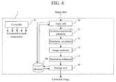
- FIG. 1 is a functional block diagram of an image processing device I according to an embodiment 1 of the present invention.
- the configuration of the image processing device 1 includes an inputter 10, an image smoother 11, a gradation distribution calculator 12, a similarity calculator 13, an image corrector 14, a resolution enhancer 15, a storage unit 16, and a controller 91.
- the inputter 10 receives moving picture data captured by imaging means (not shown).
- the inputter 10 may comprise image input ports or network connection ports and may be a tuner for TV broadcast.
- the inputter 10 may continuously acquire static image data of such as JPEG format, JPEG 2000 format, PNG format, or BMP format that is captured by imaging means such as monitoring cameras at a predetermined time interval, and may store a plurality of past, current, and future images as input images into a memory 90.
- the inputter 10 may extract static image data from moving image data of such as MotionJPEG format, MPEG format, H. 264 format, or HD/SD format, and may store a plurality of past, current, and future images as input images into the memory 90.
- the inputter 10 can acquire a plurality of past, current, and future input images from the memory 90 using such as DMA (Direct Memory Access).
- the inputter 10 may be configured by imaging means that store a plurality of past, current, and future input images into the memory 90 through buses or through networks.
- the inputter 10 may, as described later, store a plurality of past, current, and future input images into the memory 90 that are previously stored in removable storage media.
- the inputter 10 When acquiring a plurality of past, current (time t), and future input images, the inputter 10 performs delay processing if necessary. The inputter 10 outputs, to the image smoother 11, a current image and images before and after the current image.
- the image smoother 11 synthesizes a plurality of past, current, and future input images chronologically, thereby creating a smoothed image corresponding to time t.
- An example for creating the smoothed image will be described later with reference to Figure 2 .
- the gradation distribution calculator 12 calculates gradation distributions of each image region which is centered at pixels of each image. This process is performed at each pixel for each of the input image of time t and the smoothed image. An example of the gradation distribution will be described later with reference to Figure 3 .
- the similarity calculator 13 calculates a similarity between a gradation distribution of the input image at time t and of the smoothed image calculated by the gradation distribution calculator 12. An example of the similarity between the gradation distributions will be described later with reference to Figure 4 .
- the image corrector 14 corrects the input image of time t by synthesizing the input image of time t and the smoothed image.
- the synthesizing ratio between both images is modified depending on the similarity calculated by the similarity calculator 13.
- the correction above creates a corrected image of time t with reduced heat haze. An example of the correction process will be described later with reference to Figures 4-5 .
- the resolution enhancer 15 creates an image with enhanced resolution of time t from the corrected image of time t.
- An example of resolution enhancement will be described later with reference to Figure 6 .
- the storage unit 16 stores the image of time t with enhanced resolution when storing an image of time t with enhanced resolution.
- the storage unit 16 stores the input image when not storing an image of time t with enhanced resolution.
- the storage unit 16 can switch the image to be stored into the memory depending on operational modes. For example, if the mode is 1, the storage unit 16 stores a high resolution image S created by the resolution enhancer 15 into the memory 90, or alternatively outputs the high resolution image S to outside of the image processing device 1. If the mode is 0, the storage unit 16 does not store the high resolution image S into the memory 90, and outputs the input image to outside of the image processing device 1.
- the controller 91 is connected to each component in the image processing device 1. Each of the components of the image processing device 1 operates autonomously, or alternatively operates under instruction of the controller 91.
- Figure 2 is a diagram showing an operational example of the image smoother 11.
- Figure 2 shows an example where smoothed images are created using past and future images (image N-2, image N-1, image N+1, image N+2) with an image N as a reference point and using the image N itself.
- a pixel value of the image N-2 is q1(i, j) ; a pixel value of the image N-1 is q2(i, j) ; a pixel value of the image N is q3(i, j) ; a pixel value of the image N+1 is q4(i, j) ; and a pixel value of the image N+2 is q5(i, j), each located at coordinate (i, j). It is also assumed that a pixel value of the smoothed image M at coordinate (i, j) is m(i, j). It is also assumed that p1-p5 are weight factors.
- the image smoother 11 creates, by synthesizing each of the images using Equation 1 below, the smoothed image M in which each of the images is smoothed chronologically.
- the parameter D in Equation 1 is 5.
- the pixel values in Equation 1 may be in any format.
- the pixel values may be component values of three primary colors R(Red), G(Green), B(Blue) in RGB color space, or may be each component value of HSV color space (Hue, Saturation, Value).
- the displacement by which the imaged subject deforms due to heat haze follows Gaussian distribution statistically. Therefore, by smoothing pixels using a plurality of past and future images, it is possible to acquire an image in which the images subject has a shape close to its original shape.
- Figure 3 is a diagram showing that the gradation distribution calculator 12 calculates a gradation distribution using pixels of peripheral regions around a target pixel.
- the gradation distribution calculator 12 calculates a histogram H1 that represents a gradation distribution of an image region E1 (e.g. 32 ⁇ 32 pixels) including a target pixel 310 of the input image N corresponding to time t.
- the gradation distribution calculator 12 calculates a histogram H2 that represents a gradation distribution of an image region E2 corresponding to the image region E1 in the smoothed image M.
- the horizontal axes of the histograms H1 and H2 represent gradation values, and the vertical axes represent frequency (number of appearance) of the gradation values. It applies to other histograms describes below.
- the gradation distribution calculator 12 aggregates a plurality of gradation values within a same class (horizontal axis), thereby rounding the gradation values. Since image fluctuations within a same gradation range are included within a same class, the histogram with rounded gradation values has a characteristic that the histogram is robust against deformations such as heat hazes. This can be utilized to distinguish image regions deformed by heat hazes from image regions deformed by moving objects.
- deformations such as heat hazes
- Figure 4 is a diagram showing that the histogram H2 changes depending on conditions of moving objects included in past, current, and future images. It is assumed that the histogram H1 is for a region E3 that includes a target pixel 410 of the image N. The histogram H2 is for a region E4 of a target pixel 411 of the smoothed image M, and has different shapes depending on the speed of the moving object included in past, current, and future images.
- the shape of the histogram H2 is similar to that of the histogram H1, as shown in Figure 4(1) .
- the image includes a small piece of picture information different from the moving object.
- the shape of the histogram H2 is slightly different from that of the histogram H1, as shown in Figure 4 (2).
- the image includes a lot of picture information significantly different from the moving object.
- the shape of the histogram H2 is much different from that of the histogram H1, as shown in Figure 4 (3). Therefore, it is possible to perform a simplified inspection of the movement of the moving object within the image, by comparing the histogram H1 of the image N with the histogram of the smoothed image M.
- gradation distribution histogram Utilizing the above-mentioned characteristic of gradation distribution histogram, it is possible to distinguish an image fluctuation of static region due to heat hazes from a movement of moving object.
- histogram H2 of each pixel in the smoothed image M created from past, current, and future images it is possible to perform a simplified inspection of existence of moving object or its velocity.
- the similarity calculator 13 calculates a similarity between the gradation distributions calculated by the gradation distribution calculator 12, e.g. between the histograms described with reference to Figures 3-4 .
- the similarity calculator 13 calculates a distance B32(c) between the histograms utilizing Bhattacharyya distance for each of RGB components using Equation 2 below, for example ; and calculates a similarity R using B32(r) related to r component, B32(g) related to g component, and B32(b) related to b component.
- the similarity R corresponds to a distance between the histograms. Thus the smaller R is, the higher the similarity is.
- the parameter c in Equation 2 represents one of rgb.
- Figure 5 is a diagram showing an operation of the image corrector 14.
- the image corrector 14 determines pixel values of the corrected image using the input image N and the smoothed image M. Specifically, the image corrector 14 : determines a correcting value for each pixel using the similarity R calculated by the similarity calculator 13 and using two thresholds T1 and T2 (T1 ⁇ T2) ; and corrects the input image N using the correcting value.
- the regions 600 and 601 in Figure 5 correspond to such situation. This corresponds to a case when the movement pattern of the object in the image is from still to low speed. In this case, it is preferable to perform an intensive correction using the smoothed image M. Thus the pixel value of the smoothed image M is used as the correcting value.
- the regions 620 and 621 in Figure 5 correspond to such situation. This corresponds to a case when the movement pattern of the object in the image is from middle speed to high speed. In this case, if the correction is performed using the smoothed image M, a blurred image is acquired in which the movement of the moving object is smoothed. Thus the smoothed image M is not used and the pixel value of the input image N is used as the correcting value.
- the boundary of the frame border of the region 610 in Figure 5 corresponds to such situation. This corresponds to a case when the movement pattern of the object in the image is from low speed to middle speed. This is an intermediate case between the two cases above.
- the image corrector 14 calculates the correcting value by blending the pixel values of the input image N and of the smoothed image M using Equation 3 below.
- Figure 6 is an example of a sharping filter used by the resolution enhancer 15.
- the resolution enhancer 15 sharpens each correcting value using a filter such as shown in Figure 6 , for example, thereby creating the high resolution image S.
- K 0.5 so as not to intensify noises.
- FIG. 7 is a flowchart showing an operation of the image processing device 1. Hereinafter, each step in Figure 7 will be described.
- the inputter 10 acquires past, current, and future image frames, and outputs those image frames into the image smoother 11.
- the image smoother 11 calculates the smoothed image M. If the total number of past, current, and future images is 5, the suffix u in step 701 is 2.
- the gradation distribution calculator 12 calculates the histograms H1 and H2 for each of pixels of the image N and of the smoothed image M (S702).
- the similarity calculator 13 calculates the similarity R between the histograms H1 and H2 (S703).
- the image corrector 14 compares the similarity R with each of the thresholds. If R ⁇ T1, the process proceeds to step 705. Otherwise the process proceeds to step 706.
- the image corrector 14 sets the pixel value of the smoothed image M as the correcting value.
- the image corrector 14 determines whether the similarity R satisfies the threshold T1 ⁇ R ⁇ T2. If the condition is satisfied, the process proceeds to step 707. Otherwise the process proceeds to step S708.
- step S706 the image corrector 14 sets a blended value of pixel values of the image N and of the smoothed image M as the correcting value according to Equation 3 (S707). If the condition is not satisfied, the image corrector 14 sets the pixel value of the image N as the correcting value (S708).
- the resolution enhancer 15 creates the high resolution image S in which the resolution of the corrected image created by the image corrector 14 is improved (S709).
- the image corrector 14 and the resolution enhancer 15 repeat steps S702-S709 until the correcting value and pixel values with enhanced resolution are calculated for all pixels in the target image (S710).
- the image processing device 1 creates the smoothed image M using past, current (the image N), and future images ; creates the histograms H1 and H2 for each of pixels of the image N and of the smoothed image M ; and changes the correcting value for each of pixels depending on the similarity R between the histograms H1 and H2. Accordingly, it is possible to create a corrected image in which heat haze is reduced within the image.
- the image processing device 1 changes the correcting value for each of pixels depending on the similarity between the histograms H1 and H2 in which the gradation values are rounded. Accordingly, it is possible to distinguish image fluctuations at static region due to heat haze from movements of moving objects. In addition, it is possible to perform simplified inspections of movements of moving objects within the image. Thus it is possible to reduce heat hazes across the image that includes both static regions and moving objects.
- the embodiment 1 describes that static regions and moving objects are distinguished from each other by comparing a gradation distribution histogram of the smoothed image M with that of the input image N.
- a gradation distribution histogram of the smoothed image M By using the smoothed image M, it is possible to save usage of storage capacity of the memory 90, as well as to reduce the frequency of comparison to suppress processing loads.
- there is no strict hardware limit regarding those resources it is possible to compare each image frame with the input image N without creating the smoothed image M.
- a configuration example will be described where a gradation distribution histogram of the input image N is compared with that of image frames before and after the input image N.
- Figure 8 is a functional block diagram of the image processing device 1 according to the embodiment 2.
- the image processing device 1 according to the embodiment 2 does not include the image smoother 11.
- Other configurations are generally same as those of the embodiment 1. Thus differences of each component will be mainly described below.
- Figure 9 is s diagram showing an operation of the gradation distribution calculator 12.
- the gradation distribution calculator 12 calculates gradation distributions using pixels of peripheral regions around a target pixel for each of past, current, and future images.
- a histogram H1 is calculated using a partial image of a region E5 (e.g. 32 ⁇ 32 pixels) that includes a target pixel 910 of the image N-2.
- a histogram H2 is calculated using a partial image of a region E6 that includes a target pixel 911 of the image N-1 ;
- a histogram H3 is calculated using a partial image of a region E7 that includes a target pixel 912 of the image N ;
- a histogram H4 is calculated using a partial image of a region E8 that includes a target pixel 913 of the image N+1 ;
- a histogram H5 is calculated using a partial image of a region E9 that includes a target pixel 914 of the image N+2.
- Each of the histograms has rounded gradation values as in the embodiment 1.
- the similarity calculator 13 calculates similarities between gradation distributions calculated by the gradation distribution calculator 12, e.g. similarities between each of the histograms above. For example, using the histogram H3 as a reference, a distance B32(c) and a similarity R1 between the histograms H1 and H3 are calculated for each of RGB according to Equation 2. Similarly : a distance B32(c) and a similarity R2 between the histograms H2 and H3 are calculated ; a distance B32(c) and a similarity R3 between the histograms H4 and H3 are calculated ; and a distance B32(c) and a similarity R4 between the histograms H5 and H3 are calculated.
- the image corrector 14 determines pixel values of the corrected image using the input image N and the images N-2, N-1, N+1, and N+2 before and after the input image N. Specifically, the image corrector 14 : determines the correcting value for each of pixels using the similarities R1-R4 calculated by the similarity calculator 13 and two thresholds T1 and T2 (T1 ⁇ T2) ; and corrects the input image N using the correcting value.
- the image corrector 14 compares the similarity R1 between the histograms of the images N-2 and N with the thresholds ; and calculates a correcting value C1 assuming that the image N is corrected using the image N-2. If the similarity R1 ⁇ T1 (the similarity between the histograms is high), the pixel value of the image N-2 is set as the correcting value C1. If T1 ⁇ the similarity R1 ⁇ T2, a blended value of pixel values of the images N and N-2 is set as the correcting value C1. If T2 ⁇ the similarity R1, the pixel value of the image N is set as the correcting value C I.
- the image corrector 14 determines correcting values C2-C4 for the similarities R2-R4 between the histograms of other images and the image N, respectively.
- the image corrector 14 calculates finally used correcting values according to Equation 4 using the correcting values C1-C4 and pixel value n of the image N.
- ai is pixel values of each image.
- a1 represents pixel values of the image N-2
- a2 represents pixel values of the image N-1
- a3 represents pixel values of the image N+1
- a4 represents pixel values of the image N+2.
- heat haze is corrected in the regions 920 and 930 in Figure 9 using all images (image N-2, image N-1, image N, image N+1, image N+2) ; heat haze is corrected in the regions 940 and at the boundary of the frame border 950 in Figure 9 using images that satisfy the similarity Ri ⁇ T1 ; and pixel values of the image N are set for the regions 960 and 961 in Figure 9 . Therefore, it is possible to correct heat hazes across the image that includes both static regions and moving objects.
- the image resolution may be reduced.
- FIG. 10 is a flowchart showing an operation of the image processing device 1. Hereinafter, each step in Figure 10 will be described.
- the gradation distribution calculator 12 calculates the histograms H1-H5 for each of pixels of past, current, and future images (the images N-2 to N+2) outputted from the inputter 10. If the total number of past, current, and future images is 5, the suffix u in step S1001 is 2.
- the similarity calculator 13 calculates the similarities R1-R4 between the histogram H3 and each of the histograms (H1, H2, H4, H5).
- the image corrector 14 determines whether the similarity Ri ⁇ threshold T1 is satisfied. If the condition is satisfied, the process proceeds to step S1004. Otherwise the process proceeds to step S1005.
- the image corrector 14 uses the pixel value of the other image (the image other than the image N) as the correcting value Ci.
- the image corrector 14 determines whether threshold T1 ⁇ Ri ⁇ T2 is satisfied. If the condition is satisfied, the process proceeds to step S1006. Otherwise the process proceeds to step S1007.
- the image corrector 14 uses a blended value of pixel value of the image N and pixel value of the other image (the image other than the image N) as the correcting value Ci.
- n(i, j) is a pixel value of the image N at coordinate (i, j) and n2(i, j) is a pixel value of the other image at coordinate (i, j)
- e(i, j) n2(i, j)
- f(i, j) n(i, j) in Equation 3.
- the image corrector 14 uses the pixel value of the image N as the correcting value Ci.
- the image corrector 14 calculates a finally used correcting value using Equations 4 or 5 (S1009).
- the resolution enhancer 15 calculates a value in which the resolution of the correcting value is enhanced (S1010).
- the image corrector 14 and the resolution enhancer 15 repeat steps S1001-S1010 until the correcting value and pixel values with enhanced resolution are calculated for all pixels in the target image (S1011).
- the image processing device 1 creates the histograms H1-H5 for each pixel of past, current (the image N), and future images (the images N-2 to N+2) ; compares the histogram H3 with each of the histograms (HI, H2, H4, H5) to calculate the similarities R1-R4 ; and changes the correcting value for each of pixels depending on the similarities R1-R4. Accordingly, it is possible to more clearly calculate the difference between the histograms compared to the embodiment 1. In other words, the embodiment 1 compares the smoothed image M in which a plurality of images is smoothed with the image N. Thus it may be likely that the difference between the histograms is larger than that of the embodiment 2. According to the embodiment 2, it is possible to more clearly calculate the difference between the histograms, thereby selecting more appropriate correcting values.
- the image processing device 1 determines the finally used correcting value using Equations 4 or 5. Accordingly, it is possible to dynamically change the number of images used for heat haze correction for each pixel. For example, the correcting value Ci calculated from the images N-2 to N+2 and the pixel value of the image N are evenly used when using Equation 4, and the pixel values of the images N-2 to N+2 are added with weight factors depending on the similarity Ri when using Equation 5. Therefore, it is possible to correct heat hazes of images including moving objects, using appropriate numbers of images for each of pixels. Further, only image(s) selected from the images N-2 to N+2 may be used according to some other appropriate rules.
- the embodiments 1 and 2 distinguish image fluctuations due to heat haze from moving objects using histograms with rounded gradation values, thereby correcting heat hazes in images using appropriate numbers of images.
- a configuration example will be described where : a moving object removal image T is created in which the moving object is previously removed from the input image N ; and by comparing the moving object removal image T with the input image N, heat hazes are preferably removed in static regions where the moving object does not exist.
- FIG 11 is functional block diagram of the image processing device 1 according to the embodiment 3.
- the image processing device 1 according to the embodiment 3 includes a removal image creator 1111 in addition to the configurations described in the embodiments 1 or 2.
- Other configurations are generally same as those of the embodiments I and 2. Thus hereinafter the difference will be mainly described.
- the description below assumes the configuration of the embodiment 1 for the sake of convenience.
- the removal image creator 1111 creates the moving object removal image T in which the moving object is removed from the input image N using Equation 6 below.
- the parameter U has a value of 0 ⁇ U ⁇ 1.
- h i j U ⁇ v i j + 1 - U ⁇ w i j
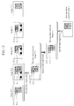
- Figure 12 is a diagram showing a processing example of the removal image creator 1111.
- the removal image creator 1111 calculates the histogram and the similarity R described in the embodiment 1, for a partial image of a region E10 that includes a target pixel 1210 (n3(i, j)) at coordinate (i, j) of the image N-3, and for a partial image of a region E11 that includes a target pixel 1211 (n2(i, j)) at coordinate (i, j) of the image N-2.
- the removal image creator 1111 then performs the same process, for a partial image of a region E14 that includes a target pixel 1214 (t2(i, j)) at coordinate (i, j) of the moving object removal image T-2, and for a partial image of a region E12 that includes a target pixel 1212 (n1(i, j)) at coordinate (i, j) of the image N-1, thereby creating the moving object removal image T-1.
- the removal image creator 1111 then performs the same process, for a partial image of a region E15 that includes a target pixel 1215 (t1(i, j)) at coordinate (i, j) of the moving object removal image T-1, and for a partial image of a region E13 that includes a target pixel 1213 (n(i, j)) at coordinate (i, j) of the image N, thereby creating the moving object removal image T.
- the gradation distribution calculator 12 calculates, for each pixel, a histogram H6 of the moving object removal image T created by the moving object removal image creator 1111, a histogram H7 of the image N, and a histogram H8 of the smoothed image M created by the image smoother 11.
- Figure 13 is a diagram showing a process of the similarity calculator 13 and of the image corrector 14.
- the similarity calculator 13 calculates a distance B32(c) and the similarity R between the histograms H7 and H8 calculated by the gradation distribution calculator 12, for each of RGB.
- the similarity calculator 13 calculates a distance B32(c) and the similarity RT between the histograms H7 and H6 calculated by the gradation distribution calculator 12, for each of RGB.
- the image corrector 14 determines pixel values of the corrected image using the input image N, the moving object removal image T, and the smoothed image M. Specifically, the image corrector 14 : determines the correcting value for each pixel using the similarities R, RT calculated by the similarity calculator 13 and two thresholds T1, T2 (T1 ⁇ T2) ; and corrects the input image N using the correcting value.
- the image corrector 14 compares the similarity R calculated by the similarity calculator 13 with each of the thresholds ; and calculates a correcting value C assuming that the image N is corrected using the smoothed image M. If the similarity R ⁇ T1 (the similarity between the histograms is high), the pixel value of the smoothed image M is set as the correcting value C. If T1 ⁇ the similarity R ⁇ T2, a blended value of pixel values of the images N and of the smoothed image M is set as the correcting value C according to Equation 3. If the similarity R > T2, the pixel value of the image N is set as the correcting value C.
- the image corrector 14 compares the similarity RT calculated by the similarity calculator 13 with each of the thresholds ; and calculates a correcting value CT assuming that the image N is corrected by the moving object removal image T. If the similarity RT ⁇ T1, the regions 1300 and 1320 in Figure 13 correspond to such situation, and the pixel value of the moving object removal image T is set as the correcting value CT. If T1 ⁇ the similarity RT ⁇ T2, the regions 1310 and the boundary of the frame border 1330 in Figure 13 correspond to such situation, and a blended value of the pixel value of the moving object removal image T and the correcting value C is set as the correcting value CT according to Equation 3. If the similarity RT > T2, the regions 1340 and 1341 in Figure 13 correspond to such situation, and the correcting value C is set as the correcting value CT. The image corrector 14 uses the calculated correcting value CT as the finally determined correcting value.
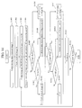
- FIG. 14 is a flowchart showing an operation of the image processing device 1. Hereinafter, each step in Figure 14 will be described.
- the removal image creator 1111 removes the moving object from the input image N according to the sequence described in Figure 12 , thereby creating the moving object removal image T. Image fluctuations due to heat haze at static regions are reduced within the moving object removal image T.
- the image smoother 11 creates the smoothed image M. Heat hazes at the moving object and at the border between the moving object and the static region are reduced within the smoothed image M.
- the gradation distribution calculator 12 calculates the histogram H7 of the image N at time t, the histogram H8 of the smoothed image M, and the histogram H6 of the moving object removal image T (S1403).
- the similarity calculator 13 calculates the similarity R between the histograms H7 and H8, and the similarity RT between the histograms H7 and H6 (S1404).
- step S1406 If R ⁇ threshold T1, the image corrector 14 proceeds to step S1406. Otherwise the image corrector 14 proceeds to step S1407.
- the image corrector 14 sets the pixel value of the smoothed image M as the correcting value C.
- the image corrector 14 determines whether the similarity R satisfies threshold T1 ⁇ R ⁇ T2. If the condition is satisfied, the process proceeds to step S1408. Otherwise the process proceeds to step S1409.
- the image corrector 14 sets a blended value of the pixel values of the smoothed image M and of the image N as the correcting value C.
- m(i, j) is a pixel value of the smoothed image M at coordinate (i, j) and n(i, j) is a pixel value of the image N at coordinate (i, j)
- the image corrector 14 sets the pixel value of the image N as the correcting value C.
- the image corrector 14 determines whether the similarity RT satisfies RT ⁇ threshold T1. If the condition is satisfied, the process proceeds to step S1411. Otherwise the process proceeds to step S1412.
- the image corrector 14 sets the pixel value of the moving object removal image T as the correcting value CT.
- the image corrector 14 determines whether the similarity RT satisfies threshold T1 ⁇ RT ⁇ T2. If the condition is satisfied, the process proceeds to step S1413. Otherwise the process proceeds to step S1414.
- the image corrector 14 sets a blended value of the pixel value of the moving object removal image T and the correcting value C as the correcting value CT.
- t0(i, j) is a pixel value of the moving object removal image T at coordinate (i, j)
- e(i, j) t0(i, j)
- f(i, j) the correcting value C in Equation 3.
- the image corrector 14 sets the correcting value C at coordinate (i, j) as the correcting value CT.
- the image corrector 14 employs the correcting value CT calculated in the foregoing process as the finally used correcting value.
- the resolution enhancer 15 calculates a value in which the resolution of the correcting value is enhanced (S1415).
- the image corrector 14 and the resolution enhancer 15 repeat steps S1403-S1415 until the correcting value and pixel values with enhanced resolution are calculated for all pixels in the target image (S1416).
- the image processing device 1 creates the moving object removal image T in addition to the smoothed image M ; and changes the correcting value for each pixel depending on the similarity R (of the histograms) between the input image N and the smoothed image M and on the similarity RT (of the histograms) between the input image N and the moving object removal image T.
- the pixel value of the moving object removal image T as the correcting value CT, it is possible to preferably reduce heat hazes of the static region within the input image N.
- the image processing device 1 uses the most appropriate one as the finally used correcting value CT depending on the similarities. Accordingly, it is possible to further effectively suppress heat hazes at static regions of the image, as well as to calculate the corrected image where heat hazes are reduced across the image that includes both static regions and moving objects.
- FIG. 15 is a functional block diagram of an imaging device 1500 according to an embodiment 4 of the present invention.
- the imaging device 1500 includes an imager 1501, an image processing device 1, and an image displayer 1502.
- the imager 1501 is an imaging device that receives light irradiated from the imaged subject, and that converts the received optical image into image data.
- the image processing device 1 is the image processing device 1 according to one of the embodiments 1-3.
- the image processing device 1 receives the image data captured by the imager 1501 to correct heat hazes.
- the image displayer 1502 is a device such as display that displays the corrected image outputted from the image processing device 1.
- the image displayer 1502 switches images depending on operational modes. For example, if the mode is 1, the image displayer 1502 displays the corrected image with reduced heat hazes. If the mode is 0, the image displayer 1502 displays the input image.
- the imaging device 1500 it is possible to provide an imaging device that displays to the photographer the corrected image in which heat hazes are reduced across the image that includes both static regions and moving objects.
- FIG 16 is a functional block diagram of a monitoring system 1600 according to an embodiment 5 of the present invention.
- the monitoring system 1600 includes an imaging device 1601, an image processing device 1, a server 1602, and a display device 1603.
- the imaging device 1601 is an imaging device such as one or more of monitoring cameras that capture image data.
- the image processing device 1 is the image processing device 1 according to one of the embodiments 1-3.
- the image processing device 1 receives the image data captured by the imaging device 1601 to correct heat hazes.
- the server 1602 is a computer that equips the image processing device 1.
- the display device 1603 is a device such as display that displays the corrected image outputted from the image processing device 1.
- the monitoring system 1600 it is possible to provide a monitoring system that displays to the monitoring operator the corrected image in which heat hazes are reduced across the image that includes both static regions and moving objects.
- FIG 17 is a functional block diagram of a coding-decoding system 1700 according to an embodiment 6 of the present invention.
- the coding-decoding system 1700 includes a coding device 1710, a decoder 1721, and a display device 1722.
- the coding device 1710 includes an imaging device 1711, an image processing device 1, and a coder 1712.
- the imaging device 1711 is an imaging device such as monitoring camera that captures image data.
- the image processing device 1 is the image processing device 1 according to one of the embodiments 1-3.
- the image processing device 1 receives the image data captured by the imaging device 1711 to correct heat hazes.
- the coder 1712 encodes the corrected image data outputted from the image processing device 1, and transmits the encoded image data toward the decoder 1721 through a network.
- the decoder 1721 decodes the transmitted corrected image data.
- the display device 1722 displays the image decoded by the decoder 1721.
- the coding-decoding system 1700 With the coding-decoding system 1700 according to the embodiment 6, it is possible to provide a coding-decoding system that displays the decoded image in which heat hazes are reduced across the image that includes both static regions and moving objects. In addition, due to the reduced heat haze within the image, the difference between images transmitted by the coder 1712 is small, and thus the coding efficiency is improved.
- the image smoother 11 creates the smoothed image M using five pieces of past, current, and future images.
- the number of images used for creating the smoothed image M is not limited to 5. It also applies to the number of images for comparing with the image N in the embodiment 2.
- the image smoother 11 may create the smoothed image M using past images within a certain period and current image, or using future images within a certain period and current image. This also achieves the same advantageous effect.
- the similarity calculator 13 calculates the similarity between the histograms utilizing Bhattacharyya distance.
- the similarity calculator 13 may calculate the similarity using other comparing methods for calculating the distance between the histograms such as a total sum of difference of frequencies between the histograms. This also achieves the same advantageous effect.
- the resolution enhancer 15 uses Figure 6 as the sharpening filter.
- the resolution enhancer 15 may enhance the resolution of image with reduced heat haze using other sharpening filters or using conventional super resolution techniques. This also achieves the same advantageous effect.
- the embodiment 3 describes that the image corrector 14 uses the moving object removal image T when calculating the correcting value CT.
- the image corrector 14 may use the moving object removal image T-l in Figure 12 .
- the image corrector 14 sets the pixel value of the moving object removal image T-l as the correcting value CT in step S1411 of Figure 14 , and sets a blended value of the pixel value of the moving object removal image T-l and the correcting value C as the correcting value CT in step S1413 of Figure 14 .
- the present invention is not limited to the embodiments, and various modified examples are included.
- the embodiments are described in detail to describe the present invention in an easily understood manner, and the embodiments are not necessarily limited to the embodiments that include all configurations described above.
- Part of the configuration of an embodiment can be replaced by the configuration of another embodiment.
- the configuration of an embodiment can be added to the configuration of another embodiment. Addition, deletion, and replacement of other configurations are also possible for part of the configurations of the embodiments.
- the configurations, the functions, the processing units, the processing means, etc. may be realized by hardware such as by designing part or all of the components by an integrated circuit.
- a processor may interpret and execute programs for realizing the functions to realize the configurations, the functions, etc., by software.
- Information, such as programs, tables, and files, for realizing the functions can be stored in a recording device, such as a memory, a hard disk, and an SSD (Solid State Drive), or in a recording medium, such as an IC card, an SD card, and a DVD.
Landscapes
- Engineering & Computer Science (AREA)
- Physics & Mathematics (AREA)
- General Physics & Mathematics (AREA)
- Theoretical Computer Science (AREA)
- Multimedia (AREA)
- Signal Processing (AREA)
- Image Processing (AREA)
- Image Analysis (AREA)
- Studio Devices (AREA)
Applications Claiming Priority (3)
| Application Number | Priority Date | Filing Date | Title |
|---|---|---|---|
| JP2013057774 | 2013-03-21 | ||
| JP2013079721A JP6104680B2 (ja) | 2013-03-21 | 2013-04-05 | 画像処理装置、撮像装置、監視システム、符号化装置、画像処理方法 |
| PCT/JP2014/051964 WO2014148114A1 (ja) | 2013-03-21 | 2014-01-29 | 画像処理装置、撮像装置、監視システム、符号化装置、画像処理方法 |
Publications (3)
| Publication Number | Publication Date |
|---|---|
| EP2977954A1 true EP2977954A1 (de) | 2016-01-27 |
| EP2977954A4 EP2977954A4 (de) | 2016-08-10 |
| EP2977954B1 EP2977954B1 (de) | 2019-03-13 |
Family
ID=51579810
Family Applications (1)
| Application Number | Title | Priority Date | Filing Date |
|---|---|---|---|
| EP14770882.0A Active EP2977954B1 (de) | 2013-03-21 | 2014-01-29 | Bildverarbeitungsvorrichtung, bildgebungsvorrichtung, überwachungssystem, codierungsvorrichtung und bildverarbeitungsverfahren |
Country Status (4)
| Country | Link |
|---|---|
| US (1) | US9706122B2 (de) |
| EP (1) | EP2977954B1 (de) |
| JP (1) | JP6104680B2 (de) |
| WO (1) | WO2014148114A1 (de) |
Cited By (2)
| Publication number | Priority date | Publication date | Assignee | Title |
|---|---|---|---|---|
| EP3021575A4 (de) * | 2013-07-09 | 2017-06-07 | Hitachi Kokusai Electric Inc. | Bildverarbeitungsvorrichtung und bildverarbeitungsverfahren |
| EP4614995A1 (de) * | 2024-03-07 | 2025-09-10 | Canon Kabushiki Kaisha | Bildgebungsvorrichtung, steuerungsverfahren, programm und speichermedium |
Families Citing this family (10)
| Publication number | Priority date | Publication date | Assignee | Title |
|---|---|---|---|---|
| JP5980294B2 (ja) * | 2014-10-27 | 2016-08-31 | キヤノン株式会社 | データ処理装置、撮像装置、およびデータ処理方法 |
| WO2016136151A1 (ja) * | 2015-02-25 | 2016-09-01 | パナソニックIpマネジメント株式会社 | 画像処理装置、画像処理方法及びそれを実行させるためのプログラム |
| JP6555940B2 (ja) * | 2015-06-12 | 2019-08-07 | キヤノン株式会社 | 被写体追跡装置、撮像装置、及び被写体追跡装置の制御方法 |
| US10521888B2 (en) * | 2015-12-23 | 2019-12-31 | Huazhong University Of Science And Technology | Aerothermal radiation effect frequency domain correction method |
| JP6700831B2 (ja) * | 2016-02-12 | 2020-05-27 | キヤノン株式会社 | 画像処理装置、撮像装置、画像処理方法、及びプログラム |
| JP6772000B2 (ja) * | 2016-08-26 | 2020-10-21 | キヤノン株式会社 | 画像処理装置、画像処理方法およびプログラム |
| CN106920232B (zh) * | 2017-02-22 | 2019-06-11 | 武汉大学 | 基于显著性检测的梯度相似度图像质量评价方法及系统 |
| JP6885896B2 (ja) * | 2017-04-10 | 2021-06-16 | 富士フイルム株式会社 | 自動レイアウト装置および自動レイアウト方法並びに自動レイアウトプログラム |
| JP6768933B2 (ja) * | 2017-04-14 | 2020-10-14 | 株式会社ソニー・インタラクティブエンタテインメント | 情報処理装置、情報処理システム、および画像処理方法 |
| JP7292123B2 (ja) * | 2019-06-20 | 2023-06-16 | キヤノン株式会社 | 撮像装置及びその制御方法、プログラム、記憶媒体 |
Family Cites Families (13)
| Publication number | Priority date | Publication date | Assignee | Title |
|---|---|---|---|---|
| US7729563B2 (en) * | 2002-08-28 | 2010-06-01 | Fujifilm Corporation | Method and device for video image processing, calculating the similarity between video frames, and acquiring a synthesized frame by synthesizing a plurality of contiguous sampled frames |
| US7548659B2 (en) * | 2005-05-13 | 2009-06-16 | Microsoft Corporation | Video enhancement |
| JP4720705B2 (ja) * | 2006-09-27 | 2011-07-13 | ソニー株式会社 | プログラム、検出方法、及び検出装置 |
| JP4245045B2 (ja) * | 2006-12-26 | 2009-03-25 | ソニー株式会社 | 撮像装置、撮像信号処理方法及びプログラム |
| JP5123713B2 (ja) * | 2008-04-04 | 2013-01-23 | キヤノン株式会社 | 画像処理装置、画像処理方法 |
| US8073199B2 (en) * | 2008-05-30 | 2011-12-06 | Drs Rsta, Inc. | Method for minimizing scintillation in dynamic images |
| JP2011229030A (ja) * | 2010-04-21 | 2011-11-10 | Sony Corp | 画像処理装置および方法、記録媒体、並びにプログラム |
| JP5885384B2 (ja) * | 2010-11-12 | 2016-03-15 | 株式会社日立国際電気 | 画像処理装置 |
| JP2012182625A (ja) | 2011-03-01 | 2012-09-20 | Nikon Corp | 撮像装置 |
| US9087390B2 (en) * | 2011-09-16 | 2015-07-21 | Adobe Systems Incorporated | High-quality upscaling of an image sequence |
| JP5362878B2 (ja) * | 2012-05-09 | 2013-12-11 | 株式会社日立国際電気 | 画像処理装置及び画像処理方法 |
| US8792718B2 (en) * | 2012-06-29 | 2014-07-29 | Adobe Systems Incorporated | Temporal matte filter for video matting |
| CN104660916B (zh) * | 2013-11-18 | 2018-09-18 | 杭州海康威视数字技术股份有限公司 | 屏幕拼接系统和视频数据流的处理方法 |
-
2013
- 2013-04-05 JP JP2013079721A patent/JP6104680B2/ja active Active
-
2014
- 2014-01-29 EP EP14770882.0A patent/EP2977954B1/de active Active
- 2014-01-29 US US14/768,772 patent/US9706122B2/en not_active Expired - Fee Related
- 2014-01-29 WO PCT/JP2014/051964 patent/WO2014148114A1/ja not_active Ceased
Cited By (2)
| Publication number | Priority date | Publication date | Assignee | Title |
|---|---|---|---|---|
| EP3021575A4 (de) * | 2013-07-09 | 2017-06-07 | Hitachi Kokusai Electric Inc. | Bildverarbeitungsvorrichtung und bildverarbeitungsverfahren |
| EP4614995A1 (de) * | 2024-03-07 | 2025-09-10 | Canon Kabushiki Kaisha | Bildgebungsvorrichtung, steuerungsverfahren, programm und speichermedium |
Also Published As
| Publication number | Publication date |
|---|---|
| WO2014148114A1 (ja) | 2014-09-25 |
| JP6104680B2 (ja) | 2017-03-29 |
| EP2977954B1 (de) | 2019-03-13 |
| US9706122B2 (en) | 2017-07-11 |
| JP2014206772A (ja) | 2014-10-30 |
| EP2977954A4 (de) | 2016-08-10 |
| US20160006936A1 (en) | 2016-01-07 |
Similar Documents
| Publication | Publication Date | Title |
|---|---|---|
| EP2977954B1 (de) | Bildverarbeitungsvorrichtung, bildgebungsvorrichtung, überwachungssystem, codierungsvorrichtung und bildverarbeitungsverfahren | |
| Shin et al. | Radiance–reflectance combined optimization and structure-guided $\ell _0 $-Norm for single image dehazing | |
| EP3021575B1 (de) | Bildverarbeitungsvorrichtung und bildverarbeitungsverfahren | |
| JP5362878B2 (ja) | 画像処理装置及び画像処理方法 | |
| US8774555B2 (en) | Image defogging method and system | |
| US8934711B2 (en) | Apparatus and method of processing image | |
| Jin et al. | Darkvisionnet: Low-light imaging via rgb-nir fusion with deep inconsistency prior | |
| US20150117540A1 (en) | Coding apparatus, decoding apparatus, coding data, coding method, decoding method, and program | |
| US20110243451A1 (en) | Image processing apparatus and method, and program | |
| US20160253787A1 (en) | Methods and systems for denoising images | |
| US20030156203A1 (en) | Image processing device | |
| EP3139343B1 (de) | Bildverarbeitungsvorrichtung, bildverarbeitungsverfahren und programm | |
| US10600158B2 (en) | Method of video stabilization using background subtraction | |
| JP2004166007A (ja) | 画像処理装置及び画像処理方法、画像処理プログラム、記憶媒体 | |
| JP2018174470A (ja) | 雑音除去装置及びプログラム | |
| US7630020B2 (en) | Image processing apparatus and its method | |
| Chen et al. | Visual depth guided image rain streaks removal via sparse coding | |
| Fuh et al. | Mcpa: A fast single image haze removal method based on the minimum channel and patchless approach | |
| Liu et al. | Joint dehazing and denoising for single nighttime image via multi-scale decomposition | |
| US10074163B2 (en) | Image correction method and image correction apparatus | |
| CN114266696B (zh) | 图像处理方法、装置、电子设备和计算机可读存储介质 | |
| Luo et al. | Restoration of user videos shared on social media | |
| CN117994160B (zh) | 一种图像处理方法及系统 | |
| KR101535196B1 (ko) | 질감 특성을 고려한 영상 분할 장치 및 그 방법 | |
| WO2025156214A1 (zh) | 一种图像处理模型的训练方法、装置、设备及存储介质 |
Legal Events
| Date | Code | Title | Description |
|---|---|---|---|
| PUAI | Public reference made under article 153(3) epc to a published international application that has entered the european phase |
Free format text: ORIGINAL CODE: 0009012 |
|
| 17P | Request for examination filed |
Effective date: 20151020 |
|
| AK | Designated contracting states |
Kind code of ref document: A1 Designated state(s): AL AT BE BG CH CY CZ DE DK EE ES FI FR GB GR HR HU IE IS IT LI LT LU LV MC MK MT NL NO PL PT RO RS SE SI SK SM TR |
|
| AX | Request for extension of the european patent |
Extension state: BA ME |
|
| DAX | Request for extension of the european patent (deleted) | ||
| REG | Reference to a national code |
Ref country code: DE Ref legal event code: R079 Ref document number: 602014042864 Country of ref document: DE Free format text: PREVIOUS MAIN CLASS: G06T0003000000 Ipc: G06T0005000000 |
|
| A4 | Supplementary search report drawn up and despatched |
Effective date: 20160712 |
|
| RIC1 | Information provided on ipc code assigned before grant |
Ipc: G06T 5/00 20060101AFI20160706BHEP Ipc: H04N 5/21 20060101ALI20160706BHEP Ipc: G06T 5/50 20060101ALI20160706BHEP Ipc: G06T 5/40 20060101ALI20160706BHEP |
|
| GRAP | Despatch of communication of intention to grant a patent |
Free format text: ORIGINAL CODE: EPIDOSNIGR1 |
|
| STAA | Information on the status of an ep patent application or granted ep patent |
Free format text: STATUS: GRANT OF PATENT IS INTENDED |
|
| INTG | Intention to grant announced |
Effective date: 20171206 |
|
| GRAJ | Information related to disapproval of communication of intention to grant by the applicant or resumption of examination proceedings by the epo deleted |
Free format text: ORIGINAL CODE: EPIDOSDIGR1 |
|
| STAA | Information on the status of an ep patent application or granted ep patent |
Free format text: STATUS: REQUEST FOR EXAMINATION WAS MADE |
|
| GRAP | Despatch of communication of intention to grant a patent |
Free format text: ORIGINAL CODE: EPIDOSNIGR1 |
|
| STAA | Information on the status of an ep patent application or granted ep patent |
Free format text: STATUS: GRANT OF PATENT IS INTENDED |
|
| INTC | Intention to grant announced (deleted) | ||
| INTG | Intention to grant announced |
Effective date: 20180508 |
|
| GRAJ | Information related to disapproval of communication of intention to grant by the applicant or resumption of examination proceedings by the epo deleted |
Free format text: ORIGINAL CODE: EPIDOSDIGR1 |
|
| STAA | Information on the status of an ep patent application or granted ep patent |
Free format text: STATUS: REQUEST FOR EXAMINATION WAS MADE |
|
| INTC | Intention to grant announced (deleted) | ||
| GRAP | Despatch of communication of intention to grant a patent |
Free format text: ORIGINAL CODE: EPIDOSNIGR1 |
|
| STAA | Information on the status of an ep patent application or granted ep patent |
Free format text: STATUS: GRANT OF PATENT IS INTENDED |
|
| INTG | Intention to grant announced |
Effective date: 20181002 |
|
| GRAS | Grant fee paid |
Free format text: ORIGINAL CODE: EPIDOSNIGR3 |
|
| GRAA | (expected) grant |
Free format text: ORIGINAL CODE: 0009210 |
|
| STAA | Information on the status of an ep patent application or granted ep patent |
Free format text: STATUS: THE PATENT HAS BEEN GRANTED |
|
| AK | Designated contracting states |
Kind code of ref document: B1 Designated state(s): AL AT BE BG CH CY CZ DE DK EE ES FI FR GB GR HR HU IE IS IT LI LT LU LV MC MK MT NL NO PL PT RO RS SE SI SK SM TR |
|
| REG | Reference to a national code |
Ref country code: GB Ref legal event code: FG4D |
|
| REG | Reference to a national code |
Ref country code: CH Ref legal event code: EP Ref country code: AT Ref legal event code: REF Ref document number: 1108725 Country of ref document: AT Kind code of ref document: T Effective date: 20190315 |
|
| REG | Reference to a national code |
Ref country code: IE Ref legal event code: FG4D |
|
| REG | Reference to a national code |
Ref country code: DE Ref legal event code: R096 Ref document number: 602014042864 Country of ref document: DE |
|
| REG | Reference to a national code |
Ref country code: NL Ref legal event code: MP Effective date: 20190313 |
|
| REG | Reference to a national code |
Ref country code: LT Ref legal event code: MG4D |
|
| PG25 | Lapsed in a contracting state [announced via postgrant information from national office to epo] |
Ref country code: LT Free format text: LAPSE BECAUSE OF FAILURE TO SUBMIT A TRANSLATION OF THE DESCRIPTION OR TO PAY THE FEE WITHIN THE PRESCRIBED TIME-LIMIT Effective date: 20190313 Ref country code: FI Free format text: LAPSE BECAUSE OF FAILURE TO SUBMIT A TRANSLATION OF THE DESCRIPTION OR TO PAY THE FEE WITHIN THE PRESCRIBED TIME-LIMIT Effective date: 20190313 Ref country code: NO Free format text: LAPSE BECAUSE OF FAILURE TO SUBMIT A TRANSLATION OF THE DESCRIPTION OR TO PAY THE FEE WITHIN THE PRESCRIBED TIME-LIMIT Effective date: 20190613 Ref country code: SE Free format text: LAPSE BECAUSE OF FAILURE TO SUBMIT A TRANSLATION OF THE DESCRIPTION OR TO PAY THE FEE WITHIN THE PRESCRIBED TIME-LIMIT Effective date: 20190313 |
|
| PG25 | Lapsed in a contracting state [announced via postgrant information from national office to epo] |
Ref country code: NL Free format text: LAPSE BECAUSE OF FAILURE TO SUBMIT A TRANSLATION OF THE DESCRIPTION OR TO PAY THE FEE WITHIN THE PRESCRIBED TIME-LIMIT Effective date: 20190313 Ref country code: RS Free format text: LAPSE BECAUSE OF FAILURE TO SUBMIT A TRANSLATION OF THE DESCRIPTION OR TO PAY THE FEE WITHIN THE PRESCRIBED TIME-LIMIT Effective date: 20190313 Ref country code: GR Free format text: LAPSE BECAUSE OF FAILURE TO SUBMIT A TRANSLATION OF THE DESCRIPTION OR TO PAY THE FEE WITHIN THE PRESCRIBED TIME-LIMIT Effective date: 20190614 Ref country code: HR Free format text: LAPSE BECAUSE OF FAILURE TO SUBMIT A TRANSLATION OF THE DESCRIPTION OR TO PAY THE FEE WITHIN THE PRESCRIBED TIME-LIMIT Effective date: 20190313 Ref country code: LV Free format text: LAPSE BECAUSE OF FAILURE TO SUBMIT A TRANSLATION OF THE DESCRIPTION OR TO PAY THE FEE WITHIN THE PRESCRIBED TIME-LIMIT Effective date: 20190313 Ref country code: BG Free format text: LAPSE BECAUSE OF FAILURE TO SUBMIT A TRANSLATION OF THE DESCRIPTION OR TO PAY THE FEE WITHIN THE PRESCRIBED TIME-LIMIT Effective date: 20190613 |
|
| REG | Reference to a national code |
Ref country code: AT Ref legal event code: MK05 Ref document number: 1108725 Country of ref document: AT Kind code of ref document: T Effective date: 20190313 |
|
| PG25 | Lapsed in a contracting state [announced via postgrant information from national office to epo] |
Ref country code: PT Free format text: LAPSE BECAUSE OF FAILURE TO SUBMIT A TRANSLATION OF THE DESCRIPTION OR TO PAY THE FEE WITHIN THE PRESCRIBED TIME-LIMIT Effective date: 20190713 Ref country code: ES Free format text: LAPSE BECAUSE OF FAILURE TO SUBMIT A TRANSLATION OF THE DESCRIPTION OR TO PAY THE FEE WITHIN THE PRESCRIBED TIME-LIMIT Effective date: 20190313 Ref country code: AL Free format text: LAPSE BECAUSE OF FAILURE TO SUBMIT A TRANSLATION OF THE DESCRIPTION OR TO PAY THE FEE WITHIN THE PRESCRIBED TIME-LIMIT Effective date: 20190313 Ref country code: EE Free format text: LAPSE BECAUSE OF FAILURE TO SUBMIT A TRANSLATION OF THE DESCRIPTION OR TO PAY THE FEE WITHIN THE PRESCRIBED TIME-LIMIT Effective date: 20190313 Ref country code: IT Free format text: LAPSE BECAUSE OF FAILURE TO SUBMIT A TRANSLATION OF THE DESCRIPTION OR TO PAY THE FEE WITHIN THE PRESCRIBED TIME-LIMIT Effective date: 20190313 Ref country code: SK Free format text: LAPSE BECAUSE OF FAILURE TO SUBMIT A TRANSLATION OF THE DESCRIPTION OR TO PAY THE FEE WITHIN THE PRESCRIBED TIME-LIMIT Effective date: 20190313 Ref country code: RO Free format text: LAPSE BECAUSE OF FAILURE TO SUBMIT A TRANSLATION OF THE DESCRIPTION OR TO PAY THE FEE WITHIN THE PRESCRIBED TIME-LIMIT Effective date: 20190313 Ref country code: CZ Free format text: LAPSE BECAUSE OF FAILURE TO SUBMIT A TRANSLATION OF THE DESCRIPTION OR TO PAY THE FEE WITHIN THE PRESCRIBED TIME-LIMIT Effective date: 20190313 |
|
| PG25 | Lapsed in a contracting state [announced via postgrant information from national office to epo] |
Ref country code: SM Free format text: LAPSE BECAUSE OF FAILURE TO SUBMIT A TRANSLATION OF THE DESCRIPTION OR TO PAY THE FEE WITHIN THE PRESCRIBED TIME-LIMIT Effective date: 20190313 Ref country code: PL Free format text: LAPSE BECAUSE OF FAILURE TO SUBMIT A TRANSLATION OF THE DESCRIPTION OR TO PAY THE FEE WITHIN THE PRESCRIBED TIME-LIMIT Effective date: 20190313 |
|
| REG | Reference to a national code |
Ref country code: DE Ref legal event code: R097 Ref document number: 602014042864 Country of ref document: DE |
|
| PG25 | Lapsed in a contracting state [announced via postgrant information from national office to epo] |
Ref country code: IS Free format text: LAPSE BECAUSE OF FAILURE TO SUBMIT A TRANSLATION OF THE DESCRIPTION OR TO PAY THE FEE WITHIN THE PRESCRIBED TIME-LIMIT Effective date: 20190713 Ref country code: AT Free format text: LAPSE BECAUSE OF FAILURE TO SUBMIT A TRANSLATION OF THE DESCRIPTION OR TO PAY THE FEE WITHIN THE PRESCRIBED TIME-LIMIT Effective date: 20190313 |
|
| PLBE | No opposition filed within time limit |
Free format text: ORIGINAL CODE: 0009261 |
|
| STAA | Information on the status of an ep patent application or granted ep patent |
Free format text: STATUS: NO OPPOSITION FILED WITHIN TIME LIMIT |
|
| PG25 | Lapsed in a contracting state [announced via postgrant information from national office to epo] |
Ref country code: DK Free format text: LAPSE BECAUSE OF FAILURE TO SUBMIT A TRANSLATION OF THE DESCRIPTION OR TO PAY THE FEE WITHIN THE PRESCRIBED TIME-LIMIT Effective date: 20190313 |
|
| 26N | No opposition filed |
Effective date: 20191216 |
|
| PG25 | Lapsed in a contracting state [announced via postgrant information from national office to epo] |
Ref country code: SI Free format text: LAPSE BECAUSE OF FAILURE TO SUBMIT A TRANSLATION OF THE DESCRIPTION OR TO PAY THE FEE WITHIN THE PRESCRIBED TIME-LIMIT Effective date: 20190313 |
|
| PG25 | Lapsed in a contracting state [announced via postgrant information from national office to epo] |
Ref country code: TR Free format text: LAPSE BECAUSE OF FAILURE TO SUBMIT A TRANSLATION OF THE DESCRIPTION OR TO PAY THE FEE WITHIN THE PRESCRIBED TIME-LIMIT Effective date: 20190313 |
|
| PG25 | Lapsed in a contracting state [announced via postgrant information from national office to epo] |
Ref country code: MC Free format text: LAPSE BECAUSE OF FAILURE TO SUBMIT A TRANSLATION OF THE DESCRIPTION OR TO PAY THE FEE WITHIN THE PRESCRIBED TIME-LIMIT Effective date: 20190313 |
|
| REG | Reference to a national code |
Ref country code: CH Ref legal event code: PL |
|
| REG | Reference to a national code |
Ref country code: BE Ref legal event code: MM Effective date: 20200131 |
|
| PG25 | Lapsed in a contracting state [announced via postgrant information from national office to epo] |
Ref country code: LU Free format text: LAPSE BECAUSE OF NON-PAYMENT OF DUE FEES Effective date: 20200129 |
|
| PG25 | Lapsed in a contracting state [announced via postgrant information from national office to epo] |
Ref country code: LI Free format text: LAPSE BECAUSE OF NON-PAYMENT OF DUE FEES Effective date: 20200131 Ref country code: BE Free format text: LAPSE BECAUSE OF NON-PAYMENT OF DUE FEES Effective date: 20200131 Ref country code: CH Free format text: LAPSE BECAUSE OF NON-PAYMENT OF DUE FEES Effective date: 20200131 |
|
| PG25 | Lapsed in a contracting state [announced via postgrant information from national office to epo] |
Ref country code: IE Free format text: LAPSE BECAUSE OF NON-PAYMENT OF DUE FEES Effective date: 20200129 |
|
| PG25 | Lapsed in a contracting state [announced via postgrant information from national office to epo] |
Ref country code: MT Free format text: LAPSE BECAUSE OF FAILURE TO SUBMIT A TRANSLATION OF THE DESCRIPTION OR TO PAY THE FEE WITHIN THE PRESCRIBED TIME-LIMIT Effective date: 20190313 Ref country code: CY Free format text: LAPSE BECAUSE OF FAILURE TO SUBMIT A TRANSLATION OF THE DESCRIPTION OR TO PAY THE FEE WITHIN THE PRESCRIBED TIME-LIMIT Effective date: 20190313 |
|
| PG25 | Lapsed in a contracting state [announced via postgrant information from national office to epo] |
Ref country code: MK Free format text: LAPSE BECAUSE OF FAILURE TO SUBMIT A TRANSLATION OF THE DESCRIPTION OR TO PAY THE FEE WITHIN THE PRESCRIBED TIME-LIMIT Effective date: 20190313 |
|
| PGFP | Annual fee paid to national office [announced via postgrant information from national office to epo] |
Ref country code: GB Payment date: 20241205 Year of fee payment: 12 |
|
| PGFP | Annual fee paid to national office [announced via postgrant information from national office to epo] |
Ref country code: FR Payment date: 20241209 Year of fee payment: 12 |
|
| REG | Reference to a national code |
Ref country code: DE Ref legal event code: R081 Ref document number: 602014042864 Country of ref document: DE Owner name: KOKUSAI DENKI ELECTRIC INC., JP Free format text: FORMER OWNER: HITACHI KOKUSAI ELECTRIC INC., TOKIO/TOKYO, JP |
|
| PGFP | Annual fee paid to national office [announced via postgrant information from national office to epo] |
Ref country code: DE Payment date: 20241203 Year of fee payment: 12 |