EP2978104A2 - Générateurs et moteurs à entrefer avec vacuum - Google Patents
Générateurs et moteurs à entrefer avec vacuum Download PDFInfo
- Publication number
- EP2978104A2 EP2978104A2 EP15178124.2A EP15178124A EP2978104A2 EP 2978104 A2 EP2978104 A2 EP 2978104A2 EP 15178124 A EP15178124 A EP 15178124A EP 2978104 A2 EP2978104 A2 EP 2978104A2
- Authority
- EP
- European Patent Office
- Prior art keywords
- rotor
- stator
- microchannels
- shaft
- windings
- Prior art date
- Legal status (The legal status is an assumption and is not a legal conclusion. Google has not performed a legal analysis and makes no representation as to the accuracy of the status listed.)
- Granted
Links
Images


Classifications
-
- H—ELECTRICITY
- H02—GENERATION; CONVERSION OR DISTRIBUTION OF ELECTRIC POWER
- H02K—DYNAMO-ELECTRIC MACHINES
- H02K3/00—Details of windings
- H02K3/04—Windings characterised by the conductor shape, form or construction, e.g. with bar conductors
- H02K3/24—Windings characterised by the conductor shape, form or construction, e.g. with bar conductors with channels or ducts for cooling medium between the conductors
-
- H—ELECTRICITY
- H02—GENERATION; CONVERSION OR DISTRIBUTION OF ELECTRIC POWER
- H02K—DYNAMO-ELECTRIC MACHINES
- H02K1/00—Details of the magnetic circuit
- H02K1/06—Details of the magnetic circuit characterised by the shape, form or construction
- H02K1/22—Rotating parts of the magnetic circuit
- H02K1/32—Rotating parts of the magnetic circuit with channels or ducts for flow of cooling medium
-
- H—ELECTRICITY
- H02—GENERATION; CONVERSION OR DISTRIBUTION OF ELECTRIC POWER
- H02K—DYNAMO-ELECTRIC MACHINES
- H02K9/00—Arrangements for cooling or ventilating
- H02K9/19—Arrangements for cooling or ventilating for machines with closed casing and closed-circuit cooling using a liquid cooling medium, e.g. oil
- H02K9/197—Arrangements for cooling or ventilating for machines with closed casing and closed-circuit cooling using a liquid cooling medium, e.g. oil in which the rotor or stator space is fluid-tight, e.g. to provide for different cooling media for rotor and stator
-
- H—ELECTRICITY
- H02—GENERATION; CONVERSION OR DISTRIBUTION OF ELECTRIC POWER
- H02K—DYNAMO-ELECTRIC MACHINES
- H02K15/00—Processes or apparatus specially adapted for manufacturing, assembling, maintaining or repairing of dynamo-electric machines
- H02K15/02—Processes or apparatus specially adapted for manufacturing, assembling, maintaining or repairing of dynamo-electric machines of stator or rotor bodies
-
- H—ELECTRICITY
- H02—GENERATION; CONVERSION OR DISTRIBUTION OF ELECTRIC POWER
- H02K—DYNAMO-ELECTRIC MACHINES
- H02K2205/00—Specific aspects not provided for in the other groups of this subclass relating to casings, enclosures, supports
- H02K2205/12—Machines characterised by means for reducing windage losses or windage noise
Definitions
- This disclosure generally relates to generators and motors and more specifically to generators and motors having a vacuum gap between their rotors and stators.
- Electrical generators and motors typically include a rotor and a stator.
- the rotor rotates either within the stationary stator or around the stationary stator in order to produce an electrical current.
- the gap between the rotor and stator is typically filled with a gas such as air in order to cool the rotor as it rotates.
- a generator or an alternating current (AC) motor includes a stator and a rotor.
- the rotor is configured to rotate at least partially within the stator or around the stator and is separated from the stator by a gap having a partial vacuum.
- the rotor includes a shaft configured to permit a flow of coolant and a plurality of microchannels formed within the rotor. The microchannels are fluidly coupled to the shaft and are configured to permit the coolant to pass from the shaft through at least a portion of the rotor in order to provide cooling for the rotor.
- Some generators and motors utilize a stationary stator and a rotor that rotates either within the stator or around the stator.
- some electrical generators utilize a rotating rotor to produce a magnetic field that induces an electrical current in windings of the stator.
- some motors utilize an alternating current (AC) in the windings of a stator to cause a rotor to rotate.
- AC alternating current
- the rotor of a generator or motor is separated from the stator by a gap that is filled with a gas such as air. The air in the gap provides cooling to the rotating rotor. The air, however, causes windage losses which reduce the efficiency of the generator or motor.
- the teachings of the disclosure recognize that it is desirable to provide a device that reduces or otherwise eliminates the windage losses of typical generators and AC motors that are due to air gaps between their rotor and stator.
- the following describes devices that utilize a vacuum gap between a rotating rotor and a stationary stator in order to reduce or prevent windage losses.
- embodiments of a rotor having microchannels for cooling the rotor are provided.
- the rotor may be a single member that is formed from an additive manufacturing process that allows microchannels for carrying coolant to be formed in any desirable shape and location within the rotor.
- FIG. 1 illustrates an example device 100 having a rotor 110 and a stator 120.
- Device 100 could be any electrical generator or AC motor.
- device 100 could be an electrical generator used in an aircraft.
- Rotor 110 may include a shaft 130.
- Rotor 110 and stator 120 may include any number and arrangement of electro-magnetics 140 that include windings 145.
- windings 145 of electro-magnetics 140 of rotor 110 may be wound about or otherwise located proximate to rotor teeth 115, as illustrated in FIGs. 5A-5C .
- rotor 110 may be positioned either partially or fully within stator 120, which is stationary.
- stator 120 which is stationary.
- rotor 110 rotates within stator 120 in order to generate an electromagnetic field and thus an electrical current within windings of stator 120.
- the engines of an aircraft may be utilized to spin rotor 110 within stator 120 in order to produce electricity for the aircraft.
- rotor 110 may alternately spin around stationary stator 120.
- rotor 110 rotates within stator 120 in response to an electromagnetic field that is generated by applying an electrical current to electro-magnetics 140 of stator 120.
- Rotor 110 of the AC motor may be used to rotate any object such as a wheel, a propeller, and the like.
- FIG. 2 illustrates a simplified cross-section of rotor 110 spinning within stator 120, according to certain embodiments.
- an air gap 150 typically exists between rotor 110 and stator 120.
- Air gap 150 is a space that is typically filled with air in order to provide cooling for spinning rotor 110.
- air gap 150 may be filled with any other gas such as helium, hydrogen, or any other gas with a lower atomic weight in order to reduce the windage losses while providing cooling.
- the air (or other gas) within air gap 150 may cause undesirable windage heat losses within the device. In other words, the device looses efficiency by having to spin rotor 110 within the air (or other gas) within air gap 150.
- undesirable arcing and corona discharge is possible across air gap 150 in some higher voltage generators operating at high altitudes, where the thin air tends to break down and cause arcing.
- FIG. 3 illustrates a simplified cross-section of a device that utilizes an oil spray 300 to cool rotor 110 spinning within stator 120, according to certain embodiments.
- Some modern airborne generators use oil spray 300 on rotor 110 to provide cooling.
- nozzles within stator 120 may be used to spray an oil onto rotor 110 as it spins in order to cool rotor 110.
- oil spray 300 to cool rotor 110 may reduce the size of air gap 150, oil may get trapped in air gap 150. This may add significantly to windage losses and heat build up of the device which may actually add to the total heat load of the aircraft.
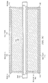
- FIG. 4 illustrates a simplified cross-section of device 100 that utilizes a vacuum gap 170 and one or more microchannels 160 in order to cool rotor 110 spinning within stator 120, according to certain embodiments.
- vacuum gap 170 is an area in which all or substantially all of the air or other gas has been removed.
- device 100 e.g., generator or AC motor
- the gap between rotor 110 and stator 120 is evacuated to at least a partial vacuum.
- forming a partial vacuum within vacuum gap 170 refers to at least partially removing gas, especially air, from vacuum gap 170 so that the gas remaining in vacuum gap 170 exerts less pressure than the atmosphere (i.e., the gaseous pressure is less that the atmospheric pressure).
- the partial vacuum within vacuum gap 170 solves two problems at once: 1) it reduces or eliminates any windage losses which in turn reduces heat load and increases efficiency, and 2) it eliminates any arcing and corona discharge possible with higher voltage generators with air gaps operating at high altitudes where thin air will tend to break down and arc. This enables a smaller gap and reduces device volume and weight.
- FIGs. 5A-5C illustrate an embodiment of rotor 110 of FIG. 4 .
- rotor 110 may include any number and configuration of rotor teeth 115.
- windings 145 are wound around rotor teeth 115 to form electro-magnetics 140.
- Windings 145 i.e., coils
- Windings 145 are heated not only by windage losses, but also by the electrical losses associated with power generation.
- windings 145 must be cooled in order for the device to operate properly. This cooling is typically provided by air or other gas in air gap 150 as rotor 110 spins within stator 120, as described above.
- FIG. 1 since the embodiments of FIG.
- microchannels 160 within rotor 110 are utilized to provide a coolant to various parts of rotor 110, thereby cooling windings 145 and rotor 110.
- microchannels 160 may be fluidly connected to shaft 130 and may run along at least portions of rotor teeth 115 (e.g., close to the rotor windings 145) as illustrated.
- a coolant such as polyalphaolefin (PAO) (or any other appropriate coolant) may then be pumped through shaft 130 and through microchannels 160 in order to provide cooling to rotor windings 145 that are wound around rotor teeth 115.
- PAO polyalphaolefin
- shaft 130 may be hollow and may connect to a rotating joint (not illustrated) on one or both ends of shaft 130. While a particular number and configuration of microchannels 160 is illustrated in FIGS. 5A-5C , other embodiments may include any appropriate configuration and number of microchannels 160. Particular example configurations of microchannels 160 are discussed further below in reference to FIGs. 6A and 6B .
- Microchannels 160 in general are small tubes or pipes formed within rotor 110 that carry coolant to and from shaft 130 in order to cool rotor 110.
- Microchannels 160 may have any appropriate cross-sectional size and shape.
- each microchannel 160 has a smaller cross-sectional diameter or width than those of windings 145.
- microchannels 160 have a round, square, or any other cross-sectional shape.
- microchannels 160 have millimeter or micron widths.
- microchannels 160 have diameters or widths between 0 and 1 millimeter (inclusive), between 1 and 10 millimeters (inclusive), or between 10 and 100 millimeters (inclusive).
- microchannels 160 have diameters or widths between 0 and 1 micrometer (inclusive), between 1 and 10 micrometers (inclusive), between 10 and 100 micrometers (inclusive), or between 100 and 1000 micrometers (inclusive).
- microchannel may have any appropriate width or diameter and is not limited to having micron widths or diameters.
- a filtered or otherwise ultra-cleaned non-reacting coolant may be utilized to prevent clogging of microchannels 160 from corrosion and particulates.
- rotor 110 is manufactured using direct or additive manufacturing (e.g., 3D printing) and is made of any appropriate material (e.g., any ferrous material such as steel or iron). These manufacturing techniques allow microchannels 160 to be produced within rotor 110 in any desired configuration that would otherwise not be possible with conventional techniques that are typically used to manufacture rotor 110. This allows cooling to be provided to any part of rotor 110 (e.g., to rotor teeth 115 and/or rotor coils wound about rotor teeth 115) without needing an air gap 150 or oil spray 300, as many conventional devices utilize.
- direct or additive manufacturing e.g., 3D printing
- any appropriate material e.g., any ferrous material such as steel or iron.
- microchannels 160 it also allows for microchannels 160 to have any size or cross-sectional shape (e.g., round, square, etc.) and to be routed anywhere in rotor 110 (e.g., close to surfaces of rotor 110), without regard to the geometric and size limitations of traditional manufacturing.
- FIGs. 6A-6B illustrate portions of rotor 110 of FIG. 4 , according to certain embodiments.
- rotor 110 includes multiple microchannels 160 within rotor teeth 115.
- Each microchannel 160 is fluidly coupled to shaft 130 via one or more lines 165.
- Lines 165 are depicted in FIGs. 6A-6B as schematic connections (i.e., lines 165 depict how microchannels 160 are conceptually connected to shaft 130 but do not necessarily depict the actual physical characteristics of lines 165 or the physical paths through rotor 110).
- each microchannel 160 may be individually coupled to shaft 130 via its own line 165 (e.g., as illustrated in detail in FIG. 5c ).
- FIG. 5c As another example, as illustrated in FIG.
- all microchannels 160 may be coupled to shaft 130 via a single line 165 (e.g., each microchannel 160 is coupled to its own line 165, and all the individual lines 165 are coupled to a main line 165 that in turn is coupled to shaft 130). While certain quantities and arrangements of microchannels 160 and lines 165 are illustrated in FIGs. 6A and 6B , any number and arrangement of microchannels 160 and lines 165 is possible. Furthermore, lines 165 may have any appropriate physical cross-sectional shape and size and, in some embodiments, may be identical to microchannels 160.
- some embodiments include many microchannels 160 that are located as close as possible to windings 145 in order to provide as much cooling as possible for windings 145 - the main heat source for rotor 110.
- microchannels 160 may, in some embodiments, have a cross-sectional diameter or width that is significantly smaller than those of windings 145. By being significantly smaller than windings 145, microchannels 160 may cause less hysteresis losses than larger pipes or channels. As magnetic fields flow through rotor 110, any discontinuities in rotor 110 may increase losses in energy due to heat.
- an apparatus or system or a component of an apparatus or system being adapted to, arranged to, capable of, configured to, enabled to, operable to, or operative to perform a particular function encompasses that apparatus, system, component, whether or not it or that particular function is activated, turned on, or unlocked, as long as that apparatus, system, or component is so adapted, arranged, capable, configured, enabled, operable, or operative.
Landscapes
- Engineering & Computer Science (AREA)
- Power Engineering (AREA)
- Manufacturing & Machinery (AREA)
- Motor Or Generator Cooling System (AREA)
Applications Claiming Priority (2)
| Application Number | Priority Date | Filing Date | Title |
|---|---|---|---|
| US201462028016P | 2014-07-23 | 2014-07-23 | |
| US14/803,999 US10033236B2 (en) | 2014-07-23 | 2015-07-20 | Vacuum gap generators and motors |
Publications (3)
| Publication Number | Publication Date |
|---|---|
| EP2978104A2 true EP2978104A2 (fr) | 2016-01-27 |
| EP2978104A3 EP2978104A3 (fr) | 2016-08-10 |
| EP2978104B1 EP2978104B1 (fr) | 2020-02-26 |
Family
ID=53836387
Family Applications (1)
| Application Number | Title | Priority Date | Filing Date |
|---|---|---|---|
| EP15178124.2A Active EP2978104B1 (fr) | 2014-07-23 | 2015-07-23 | Générateurs et moteurs à entrefer avec vacuum |
Country Status (2)
| Country | Link |
|---|---|
| US (1) | US10033236B2 (fr) |
| EP (1) | EP2978104B1 (fr) |
Cited By (3)
| Publication number | Priority date | Publication date | Assignee | Title |
|---|---|---|---|---|
| EP3247028A1 (fr) * | 2016-05-13 | 2017-11-22 | Otis Elevator Company | Élément d'entraînement d'ascenseur magnétique et procédé de fabrication |
| CN110474498A (zh) * | 2018-05-10 | 2019-11-19 | 通用电气航空系统有限责任公司 | 电机的增材制造的组件 |
| WO2021074526A1 (fr) * | 2019-10-16 | 2021-04-22 | Commissariat A L'energie Atomique Et Aux Energies Alternatives | Pièce monobloc et ferromagnétique d'une machine électrique tournante |
Families Citing this family (5)
| Publication number | Priority date | Publication date | Assignee | Title |
|---|---|---|---|---|
| US10476358B2 (en) * | 2017-01-13 | 2019-11-12 | General Electric Company | Methods for manufacturing an electric machine |
| GB201714242D0 (en) * | 2017-09-05 | 2017-10-18 | Rolls Royce Plc | Electrical machine rotor |
| EP3799264B1 (fr) | 2019-09-30 | 2023-04-19 | Siemens Aktiengesellschaft | Arbre d'entraînement d'une machine dynamoélectrique |
| WO2021231766A1 (fr) * | 2020-05-14 | 2021-11-18 | The Texas A&M University System | Machine électrique à haute densité de couple dotée d'enroulements d'extrémité refroidis directement |
| DE102022004623B3 (de) | 2022-12-09 | 2024-02-29 | Mercedes-Benz Group AG | Antriebseinrichtung für ein Kraftfahrzeug und Verfahren zum Betreiben einer Antriebseinrichtung |
Family Cites Families (12)
| Publication number | Priority date | Publication date | Assignee | Title |
|---|---|---|---|---|
| GB1455818A (en) * | 1972-10-31 | 1976-11-17 | Int Research & Dev Co Ltd | Dynamo-electric machines |
| FR2319233A1 (fr) | 1975-07-22 | 1977-02-18 | Alsthom Cgee | Machine tournante utilisant un fluide de refroidissement amene par joint tournant |
| SU625290A1 (ru) | 1976-11-30 | 1978-09-25 | Специальное Конструкторское Бюро "Энергохиммаш" | Электрическа машина |
| DE2854059A1 (de) | 1978-12-14 | 1980-07-17 | Kraftwerk Union Ag | Kuehlsystem fuer laeufer elektrischer maschinen, insbesondere fuer turbogeneratoren-laeufer mit supraleitender feldwicklung |
| JPH04145863A (ja) | 1990-10-05 | 1992-05-19 | Toshiba Corp | 超電導回転電機 |
| US5122704A (en) * | 1990-10-25 | 1992-06-16 | Sundstrand Corporation | Composite rotor sleeve |
| WO2000055958A1 (fr) * | 1999-03-17 | 2000-09-21 | Hitachi, Ltd. | Machine dynamoelectrique |
| US6553773B2 (en) * | 2001-05-15 | 2003-04-29 | General Electric Company | Cryogenic cooling system for rotor having a high temperature super-conducting field winding |
| IL160823A0 (en) * | 2001-09-13 | 2004-08-31 | Lewis B Sibley | Flywheel energy storage systems |
| US8970074B2 (en) | 2010-11-01 | 2015-03-03 | Mission Motor Company | Electric motor and method of cooling |
| US20130195695A1 (en) * | 2012-01-30 | 2013-08-01 | General Electric Company | Hollow rotor motor and systems comprising the same |
| US8896167B2 (en) | 2012-05-25 | 2014-11-25 | Deere & Company | Electric machine rotor cooling method |
-
2015
- 2015-07-20 US US14/803,999 patent/US10033236B2/en active Active
- 2015-07-23 EP EP15178124.2A patent/EP2978104B1/fr active Active
Non-Patent Citations (1)
| Title |
|---|
| None |
Cited By (6)
| Publication number | Priority date | Publication date | Assignee | Title |
|---|---|---|---|---|
| EP3247028A1 (fr) * | 2016-05-13 | 2017-11-22 | Otis Elevator Company | Élément d'entraînement d'ascenseur magnétique et procédé de fabrication |
| US10587180B2 (en) | 2016-05-13 | 2020-03-10 | Otis Elevator Company | Magnetic elevator drive member and method of manufacture |
| CN110474498A (zh) * | 2018-05-10 | 2019-11-19 | 通用电气航空系统有限责任公司 | 电机的增材制造的组件 |
| CN110474498B (zh) * | 2018-05-10 | 2021-12-24 | 通用电气航空系统有限责任公司 | 电机的增材制造的组件 |
| WO2021074526A1 (fr) * | 2019-10-16 | 2021-04-22 | Commissariat A L'energie Atomique Et Aux Energies Alternatives | Pièce monobloc et ferromagnétique d'une machine électrique tournante |
| FR3102316A1 (fr) * | 2019-10-16 | 2021-04-23 | Commissariat A L'energie Atomique Et Aux Energies Alternatives | pièce monobloc et ferromagnétique d’une machine électrique tournante |
Also Published As
| Publication number | Publication date |
|---|---|
| US10033236B2 (en) | 2018-07-24 |
| US20160028283A1 (en) | 2016-01-28 |
| EP2978104B1 (fr) | 2020-02-26 |
| EP2978104A3 (fr) | 2016-08-10 |
Similar Documents
| Publication | Publication Date | Title |
|---|---|---|
| US10033236B2 (en) | Vacuum gap generators and motors | |
| US8803399B2 (en) | Rotor with reinforced squirrel-cage conductive body and manufacturing method thereof | |
| US10381889B2 (en) | Permanent magnet machine with segmented sleeve for magnets | |
| US9837868B2 (en) | Rotor assembly for an electric machine | |
| US9041232B2 (en) | Electric generator system | |
| US10826357B2 (en) | Harmonic shunting electric motor with faceted shaft for improved torque transmission | |
| US20100327589A1 (en) | Gas turbine with wired shaft forming part of a generator/motor assembly | |
| US11063494B2 (en) | Electrical machine apparatus | |
| EP3376640A1 (fr) | Machine électrique à porte-aimant séparable | |
| US8350656B2 (en) | Rotary transformer | |
| EP3410574B1 (fr) | Machines synchrones hybrides | |
| US11916444B2 (en) | Electric loss shunting in a chiller-compressor-motor-drive system | |
| US11211836B2 (en) | Stator assembly | |
| US10344613B2 (en) | Hyperjet superconducting turbine blisk propulsion and power generation | |
| JP2022514074A (ja) | 永久磁石を強制的に消磁するための装置を含む電気機械 | |
| US20080157622A1 (en) | Fault-tolerant permanent magnet machine | |
| US10326344B2 (en) | Polyphase transverse flux machine | |
| CN108288879B (zh) | 用于电机的定子支承 | |
| US20190089211A1 (en) | Electric machine comprising a stator provided with an inner tubular sleeve | |
| US20220052572A1 (en) | Electric machine and hybrid electric vehicle | |
| CN110784048B (zh) | 定子组件 | |
| CN103997175A (zh) | 一种独立绕线的外转子电机 | |
| CN104919681A (zh) | 用飞轮存储电力的电子装置 |
Legal Events
| Date | Code | Title | Description |
|---|---|---|---|
| PUAI | Public reference made under article 153(3) epc to a published international application that has entered the european phase |
Free format text: ORIGINAL CODE: 0009012 |
|
| AK | Designated contracting states |
Kind code of ref document: A2 Designated state(s): AL AT BE BG CH CY CZ DE DK EE ES FI FR GB GR HR HU IE IS IT LI LT LU LV MC MK MT NL NO PL PT RO RS SE SI SK SM TR |
|
| AX | Request for extension of the european patent |
Extension state: BA ME |
|
| PUAL | Search report despatched |
Free format text: ORIGINAL CODE: 0009013 |
|
| RIC1 | Information provided on ipc code assigned before grant |
Ipc: H02K 15/02 20060101ALI20160621BHEP Ipc: H02K 1/32 20060101AFI20160621BHEP Ipc: H02K 9/197 20060101ALI20160621BHEP |
|
| AK | Designated contracting states |
Kind code of ref document: A3 Designated state(s): AL AT BE BG CH CY CZ DE DK EE ES FI FR GB GR HR HU IE IS IT LI LT LU LV MC MK MT NL NO PL PT RO RS SE SI SK SM TR |
|
| AX | Request for extension of the european patent |
Extension state: BA ME |
|
| RIC1 | Information provided on ipc code assigned before grant |
Ipc: H02K 15/02 20060101ALI20160707BHEP Ipc: H02K 9/197 20060101ALI20160707BHEP Ipc: H02K 1/32 20060101AFI20160707BHEP |
|
| STAA | Information on the status of an ep patent application or granted ep patent |
Free format text: STATUS: REQUEST FOR EXAMINATION WAS MADE |
|
| 17P | Request for examination filed |
Effective date: 20170130 |
|
| RBV | Designated contracting states (corrected) |
Designated state(s): AL AT BE BG CH CY CZ DE DK EE ES FI FR GB GR HR HU IE IS IT LI LT LU LV MC MK MT NL NO PL PT RO RS SE SI SK SM TR |
|
| STAA | Information on the status of an ep patent application or granted ep patent |
Free format text: STATUS: EXAMINATION IS IN PROGRESS |
|
| 17Q | First examination report despatched |
Effective date: 20190308 |
|
| GRAP | Despatch of communication of intention to grant a patent |
Free format text: ORIGINAL CODE: EPIDOSNIGR1 |
|
| STAA | Information on the status of an ep patent application or granted ep patent |
Free format text: STATUS: GRANT OF PATENT IS INTENDED |
|
| INTG | Intention to grant announced |
Effective date: 20191025 |
|
| GRAS | Grant fee paid |
Free format text: ORIGINAL CODE: EPIDOSNIGR3 |
|
| GRAA | (expected) grant |
Free format text: ORIGINAL CODE: 0009210 |
|
| STAA | Information on the status of an ep patent application or granted ep patent |
Free format text: STATUS: THE PATENT HAS BEEN GRANTED |
|
| AK | Designated contracting states |
Kind code of ref document: B1 Designated state(s): AL AT BE BG CH CY CZ DE DK EE ES FI FR GB GR HR HU IE IS IT LI LT LU LV MC MK MT NL NO PL PT RO RS SE SI SK SM TR |
|
| REG | Reference to a national code |
Ref country code: GB Ref legal event code: FG4D |
|
| REG | Reference to a national code |
Ref country code: CH Ref legal event code: EP |
|
| REG | Reference to a national code |
Ref country code: AT Ref legal event code: REF Ref document number: 1238839 Country of ref document: AT Kind code of ref document: T Effective date: 20200315 |
|
| REG | Reference to a national code |
Ref country code: IE Ref legal event code: FG4D |
|
| REG | Reference to a national code |
Ref country code: DE Ref legal event code: R096 Ref document number: 602015047616 Country of ref document: DE |
|
| PG25 | Lapsed in a contracting state [announced via postgrant information from national office to epo] |
Ref country code: FI Free format text: LAPSE BECAUSE OF FAILURE TO SUBMIT A TRANSLATION OF THE DESCRIPTION OR TO PAY THE FEE WITHIN THE PRESCRIBED TIME-LIMIT Effective date: 20200226 Ref country code: RS Free format text: LAPSE BECAUSE OF FAILURE TO SUBMIT A TRANSLATION OF THE DESCRIPTION OR TO PAY THE FEE WITHIN THE PRESCRIBED TIME-LIMIT Effective date: 20200226 Ref country code: NO Free format text: LAPSE BECAUSE OF FAILURE TO SUBMIT A TRANSLATION OF THE DESCRIPTION OR TO PAY THE FEE WITHIN THE PRESCRIBED TIME-LIMIT Effective date: 20200526 |
|
| REG | Reference to a national code |
Ref country code: NL Ref legal event code: MP Effective date: 20200226 |
|
| REG | Reference to a national code |
Ref country code: LT Ref legal event code: MG4D |
|
| PG25 | Lapsed in a contracting state [announced via postgrant information from national office to epo] |
Ref country code: IS Free format text: LAPSE BECAUSE OF FAILURE TO SUBMIT A TRANSLATION OF THE DESCRIPTION OR TO PAY THE FEE WITHIN THE PRESCRIBED TIME-LIMIT Effective date: 20200626 Ref country code: BG Free format text: LAPSE BECAUSE OF FAILURE TO SUBMIT A TRANSLATION OF THE DESCRIPTION OR TO PAY THE FEE WITHIN THE PRESCRIBED TIME-LIMIT Effective date: 20200526 Ref country code: SE Free format text: LAPSE BECAUSE OF FAILURE TO SUBMIT A TRANSLATION OF THE DESCRIPTION OR TO PAY THE FEE WITHIN THE PRESCRIBED TIME-LIMIT Effective date: 20200226 Ref country code: LV Free format text: LAPSE BECAUSE OF FAILURE TO SUBMIT A TRANSLATION OF THE DESCRIPTION OR TO PAY THE FEE WITHIN THE PRESCRIBED TIME-LIMIT Effective date: 20200226 Ref country code: HR Free format text: LAPSE BECAUSE OF FAILURE TO SUBMIT A TRANSLATION OF THE DESCRIPTION OR TO PAY THE FEE WITHIN THE PRESCRIBED TIME-LIMIT Effective date: 20200226 Ref country code: GR Free format text: LAPSE BECAUSE OF FAILURE TO SUBMIT A TRANSLATION OF THE DESCRIPTION OR TO PAY THE FEE WITHIN THE PRESCRIBED TIME-LIMIT Effective date: 20200527 |
|
| PG25 | Lapsed in a contracting state [announced via postgrant information from national office to epo] |
Ref country code: NL Free format text: LAPSE BECAUSE OF FAILURE TO SUBMIT A TRANSLATION OF THE DESCRIPTION OR TO PAY THE FEE WITHIN THE PRESCRIBED TIME-LIMIT Effective date: 20200226 |
|
| PG25 | Lapsed in a contracting state [announced via postgrant information from national office to epo] |
Ref country code: PT Free format text: LAPSE BECAUSE OF FAILURE TO SUBMIT A TRANSLATION OF THE DESCRIPTION OR TO PAY THE FEE WITHIN THE PRESCRIBED TIME-LIMIT Effective date: 20200719 Ref country code: EE Free format text: LAPSE BECAUSE OF FAILURE TO SUBMIT A TRANSLATION OF THE DESCRIPTION OR TO PAY THE FEE WITHIN THE PRESCRIBED TIME-LIMIT Effective date: 20200226 Ref country code: DK Free format text: LAPSE BECAUSE OF FAILURE TO SUBMIT A TRANSLATION OF THE DESCRIPTION OR TO PAY THE FEE WITHIN THE PRESCRIBED TIME-LIMIT Effective date: 20200226 Ref country code: RO Free format text: LAPSE BECAUSE OF FAILURE TO SUBMIT A TRANSLATION OF THE DESCRIPTION OR TO PAY THE FEE WITHIN THE PRESCRIBED TIME-LIMIT Effective date: 20200226 Ref country code: SK Free format text: LAPSE BECAUSE OF FAILURE TO SUBMIT A TRANSLATION OF THE DESCRIPTION OR TO PAY THE FEE WITHIN THE PRESCRIBED TIME-LIMIT Effective date: 20200226 Ref country code: SM Free format text: LAPSE BECAUSE OF FAILURE TO SUBMIT A TRANSLATION OF THE DESCRIPTION OR TO PAY THE FEE WITHIN THE PRESCRIBED TIME-LIMIT Effective date: 20200226 Ref country code: LT Free format text: LAPSE BECAUSE OF FAILURE TO SUBMIT A TRANSLATION OF THE DESCRIPTION OR TO PAY THE FEE WITHIN THE PRESCRIBED TIME-LIMIT Effective date: 20200226 Ref country code: CZ Free format text: LAPSE BECAUSE OF FAILURE TO SUBMIT A TRANSLATION OF THE DESCRIPTION OR TO PAY THE FEE WITHIN THE PRESCRIBED TIME-LIMIT Effective date: 20200226 Ref country code: ES Free format text: LAPSE BECAUSE OF FAILURE TO SUBMIT A TRANSLATION OF THE DESCRIPTION OR TO PAY THE FEE WITHIN THE PRESCRIBED TIME-LIMIT Effective date: 20200226 |
|
| REG | Reference to a national code |
Ref country code: AT Ref legal event code: MK05 Ref document number: 1238839 Country of ref document: AT Kind code of ref document: T Effective date: 20200226 |
|
| REG | Reference to a national code |
Ref country code: DE Ref legal event code: R097 Ref document number: 602015047616 Country of ref document: DE |
|
| PLBE | No opposition filed within time limit |
Free format text: ORIGINAL CODE: 0009261 |
|
| STAA | Information on the status of an ep patent application or granted ep patent |
Free format text: STATUS: NO OPPOSITION FILED WITHIN TIME LIMIT |
|
| PG25 | Lapsed in a contracting state [announced via postgrant information from national office to epo] |
Ref country code: AT Free format text: LAPSE BECAUSE OF FAILURE TO SUBMIT A TRANSLATION OF THE DESCRIPTION OR TO PAY THE FEE WITHIN THE PRESCRIBED TIME-LIMIT Effective date: 20200226 |
|
| 26N | No opposition filed |
Effective date: 20201127 |
|
| PG25 | Lapsed in a contracting state [announced via postgrant information from national office to epo] |
Ref country code: SI Free format text: LAPSE BECAUSE OF FAILURE TO SUBMIT A TRANSLATION OF THE DESCRIPTION OR TO PAY THE FEE WITHIN THE PRESCRIBED TIME-LIMIT Effective date: 20200226 Ref country code: PL Free format text: LAPSE BECAUSE OF FAILURE TO SUBMIT A TRANSLATION OF THE DESCRIPTION OR TO PAY THE FEE WITHIN THE PRESCRIBED TIME-LIMIT Effective date: 20200226 Ref country code: MC Free format text: LAPSE BECAUSE OF FAILURE TO SUBMIT A TRANSLATION OF THE DESCRIPTION OR TO PAY THE FEE WITHIN THE PRESCRIBED TIME-LIMIT Effective date: 20200226 |
|
| REG | Reference to a national code |
Ref country code: CH Ref legal event code: PL |
|
| REG | Reference to a national code |
Ref country code: BE Ref legal event code: MM Effective date: 20200731 |
|
| PG25 | Lapsed in a contracting state [announced via postgrant information from national office to epo] |
Ref country code: CH Free format text: LAPSE BECAUSE OF NON-PAYMENT OF DUE FEES Effective date: 20200731 Ref country code: LU Free format text: LAPSE BECAUSE OF NON-PAYMENT OF DUE FEES Effective date: 20200723 Ref country code: LI Free format text: LAPSE BECAUSE OF NON-PAYMENT OF DUE FEES Effective date: 20200731 |
|
| PG25 | Lapsed in a contracting state [announced via postgrant information from national office to epo] |
Ref country code: BE Free format text: LAPSE BECAUSE OF NON-PAYMENT OF DUE FEES Effective date: 20200731 |
|
| PG25 | Lapsed in a contracting state [announced via postgrant information from national office to epo] |
Ref country code: IE Free format text: LAPSE BECAUSE OF NON-PAYMENT OF DUE FEES Effective date: 20200723 |
|
| PG25 | Lapsed in a contracting state [announced via postgrant information from national office to epo] |
Ref country code: TR Free format text: LAPSE BECAUSE OF FAILURE TO SUBMIT A TRANSLATION OF THE DESCRIPTION OR TO PAY THE FEE WITHIN THE PRESCRIBED TIME-LIMIT Effective date: 20200226 Ref country code: MT Free format text: LAPSE BECAUSE OF FAILURE TO SUBMIT A TRANSLATION OF THE DESCRIPTION OR TO PAY THE FEE WITHIN THE PRESCRIBED TIME-LIMIT Effective date: 20200226 Ref country code: CY Free format text: LAPSE BECAUSE OF FAILURE TO SUBMIT A TRANSLATION OF THE DESCRIPTION OR TO PAY THE FEE WITHIN THE PRESCRIBED TIME-LIMIT Effective date: 20200226 |
|
| PG25 | Lapsed in a contracting state [announced via postgrant information from national office to epo] |
Ref country code: MK Free format text: LAPSE BECAUSE OF FAILURE TO SUBMIT A TRANSLATION OF THE DESCRIPTION OR TO PAY THE FEE WITHIN THE PRESCRIBED TIME-LIMIT Effective date: 20200226 Ref country code: AL Free format text: LAPSE BECAUSE OF FAILURE TO SUBMIT A TRANSLATION OF THE DESCRIPTION OR TO PAY THE FEE WITHIN THE PRESCRIBED TIME-LIMIT Effective date: 20200226 |
|
| P01 | Opt-out of the competence of the unified patent court (upc) registered |
Effective date: 20230530 |
|
| PGFP | Annual fee paid to national office [announced via postgrant information from national office to epo] |
Ref country code: DE Payment date: 20250729 Year of fee payment: 11 |
|
| PGFP | Annual fee paid to national office [announced via postgrant information from national office to epo] |
Ref country code: IT Payment date: 20250721 Year of fee payment: 11 |
|
| PGFP | Annual fee paid to national office [announced via postgrant information from national office to epo] |
Ref country code: GB Payment date: 20250728 Year of fee payment: 11 |
|
| PGFP | Annual fee paid to national office [announced via postgrant information from national office to epo] |
Ref country code: FR Payment date: 20250725 Year of fee payment: 11 |