EP2978123A1 - Procede de realisation d'un generateur tribo -electrique a polymere dielectrique rugueux - Google Patents
Procede de realisation d'un generateur tribo -electrique a polymere dielectrique rugueux Download PDFInfo
- Publication number
- EP2978123A1 EP2978123A1 EP15177468.4A EP15177468A EP2978123A1 EP 2978123 A1 EP2978123 A1 EP 2978123A1 EP 15177468 A EP15177468 A EP 15177468A EP 2978123 A1 EP2978123 A1 EP 2978123A1
- Authority
- EP
- European Patent Office
- Prior art keywords
- polymer material
- dielectric polymer
- triboelectric
- trfe
- vdf
- Prior art date
- Legal status (The legal status is an assumption and is not a legal conclusion. Google has not performed a legal analysis and makes no representation as to the accuracy of the status listed.)
- Granted
Links
- 238000000034 method Methods 0.000 title claims description 19
- 229920000642 polymer Polymers 0.000 title claims description 15
- 238000004519 manufacturing process Methods 0.000 title claims description 9
- 239000002861 polymer material Substances 0.000 claims abstract description 51
- 238000010438 heat treatment Methods 0.000 claims abstract description 9
- 239000000463 material Substances 0.000 claims description 28
- 238000000137 annealing Methods 0.000 claims description 16
- BBEAQIROQSPTKN-UHFFFAOYSA-N pyrene Chemical compound C1=CC=C2C=CC3=CC=CC4=CC=C1C2=C43 BBEAQIROQSPTKN-UHFFFAOYSA-N 0.000 claims description 16
- 229920001897 terpolymer Polymers 0.000 claims description 14
- 239000000654 additive Substances 0.000 claims description 13
- 230000000996 additive effect Effects 0.000 claims description 13
- 239000002033 PVDF binder Substances 0.000 claims description 12
- 229920002981 polyvinylidene fluoride Polymers 0.000 claims description 12
- OKTJSMMVPCPJKN-UHFFFAOYSA-N Carbon Chemical compound [C] OKTJSMMVPCPJKN-UHFFFAOYSA-N 0.000 claims description 11
- 238000002425 crystallisation Methods 0.000 claims description 11
- 230000008025 crystallization Effects 0.000 claims description 11
- 230000000694 effects Effects 0.000 claims description 11
- 229910021389 graphene Inorganic materials 0.000 claims description 9
- GVEPBJHOBDJJJI-UHFFFAOYSA-N fluoranthrene Natural products C1=CC(C2=CC=CC=C22)=C3C2=CC=CC3=C1 GVEPBJHOBDJJJI-UHFFFAOYSA-N 0.000 claims description 8
- 229920001577 copolymer Polymers 0.000 claims description 6
- 230000002209 hydrophobic effect Effects 0.000 claims description 6
- 230000005855 radiation Effects 0.000 claims description 6
- 150000001875 compounds Chemical class 0.000 claims description 3
- 230000008569 process Effects 0.000 claims description 3
- 239000003989 dielectric material Substances 0.000 description 14
- 239000000203 mixture Substances 0.000 description 9
- 238000000151 deposition Methods 0.000 description 6
- 230000008021 deposition Effects 0.000 description 5
- 239000004205 dimethyl polysiloxane Substances 0.000 description 5
- 229920000435 poly(dimethylsiloxane) Polymers 0.000 description 5
- 239000004696 Poly ether ether ketone Substances 0.000 description 4
- 239000004642 Polyimide Substances 0.000 description 4
- 229920002530 polyetherether ketone Polymers 0.000 description 4
- 229920000139 polyethylene terephthalate Polymers 0.000 description 4
- 239000005020 polyethylene terephthalate Substances 0.000 description 4
- 229920001721 polyimide Polymers 0.000 description 4
- 239000002904 solvent Substances 0.000 description 4
- ZMXDDKWLCZADIW-UHFFFAOYSA-N N,N-Dimethylformamide Chemical compound CN(C)C=O ZMXDDKWLCZADIW-UHFFFAOYSA-N 0.000 description 3
- 239000004020 conductor Substances 0.000 description 3
- 239000010931 gold Substances 0.000 description 3
- 239000011159 matrix material Substances 0.000 description 3
- BASFCYQUMIYNBI-UHFFFAOYSA-N platinum Chemical compound [Pt] BASFCYQUMIYNBI-UHFFFAOYSA-N 0.000 description 3
- -1 polydimethylsiloxane Polymers 0.000 description 3
- 238000012360 testing method Methods 0.000 description 3
- 230000007704 transition Effects 0.000 description 3
- CSCPPACGZOOCGX-UHFFFAOYSA-N Acetone Chemical compound CC(C)=O CSCPPACGZOOCGX-UHFFFAOYSA-N 0.000 description 2
- VGGSQFUCUMXWEO-UHFFFAOYSA-N Ethene Chemical compound C=C VGGSQFUCUMXWEO-UHFFFAOYSA-N 0.000 description 2
- 239000005977 Ethylene Substances 0.000 description 2
- 239000004793 Polystyrene Substances 0.000 description 2
- BQCADISMDOOEFD-UHFFFAOYSA-N Silver Chemical compound [Ag] BQCADISMDOOEFD-UHFFFAOYSA-N 0.000 description 2
- 230000008901 benefit Effects 0.000 description 2
- 230000015572 biosynthetic process Effects 0.000 description 2
- 239000001913 cellulose Substances 0.000 description 2
- 229920002678 cellulose Polymers 0.000 description 2
- 230000001143 conditioned effect Effects 0.000 description 2
- 239000010949 copper Substances 0.000 description 2
- BGTOWKSIORTVQH-UHFFFAOYSA-N cyclopentanone Chemical compound O=C1CCCC1 BGTOWKSIORTVQH-UHFFFAOYSA-N 0.000 description 2
- PCHJSUWPFVWCPO-UHFFFAOYSA-N gold Chemical compound [Au] PCHJSUWPFVWCPO-UHFFFAOYSA-N 0.000 description 2
- 229910052737 gold Inorganic materials 0.000 description 2
- 239000002184 metal Substances 0.000 description 2
- 229910052751 metal Inorganic materials 0.000 description 2
- 238000012986 modification Methods 0.000 description 2
- 230000004048 modification Effects 0.000 description 2
- 238000005240 physical vapour deposition Methods 0.000 description 2
- 229920002223 polystyrene Polymers 0.000 description 2
- 239000011148 porous material Substances 0.000 description 2
- 238000011084 recovery Methods 0.000 description 2
- 238000007650 screen-printing Methods 0.000 description 2
- 229910052709 silver Inorganic materials 0.000 description 2
- 239000004332 silver Substances 0.000 description 2
- 238000004528 spin coating Methods 0.000 description 2
- 238000005507 spraying Methods 0.000 description 2
- 239000010936 titanium Substances 0.000 description 2
- RYGMFSIKBFXOCR-UHFFFAOYSA-N Copper Chemical compound [Cu] RYGMFSIKBFXOCR-UHFFFAOYSA-N 0.000 description 1
- FXHOOIRPVKKKFG-UHFFFAOYSA-N N,N-Dimethylacetamide Chemical compound CN(C)C(C)=O FXHOOIRPVKKKFG-UHFFFAOYSA-N 0.000 description 1
- RTAQQCXQSZGOHL-UHFFFAOYSA-N Titanium Chemical compound [Ti] RTAQQCXQSZGOHL-UHFFFAOYSA-N 0.000 description 1
- 229910052782 aluminium Inorganic materials 0.000 description 1
- XAGFODPZIPBFFR-UHFFFAOYSA-N aluminium Chemical compound [Al] XAGFODPZIPBFFR-UHFFFAOYSA-N 0.000 description 1
- 239000003990 capacitor Substances 0.000 description 1
- 229910052799 carbon Inorganic materials 0.000 description 1
- 230000008859 change Effects 0.000 description 1
- 229910052802 copper Inorganic materials 0.000 description 1
- 230000007423 decrease Effects 0.000 description 1
- 238000011161 development Methods 0.000 description 1
- 238000011049 filling Methods 0.000 description 1
- AMGQUBHHOARCQH-UHFFFAOYSA-N indium;oxotin Chemical compound [In].[Sn]=O AMGQUBHHOARCQH-UHFFFAOYSA-N 0.000 description 1
- 238000005259 measurement Methods 0.000 description 1
- 239000007769 metal material Substances 0.000 description 1
- 239000002985 plastic film Substances 0.000 description 1
- 229920006255 plastic film Polymers 0.000 description 1
- 229910052697 platinum Inorganic materials 0.000 description 1
- 239000000843 powder Substances 0.000 description 1
- 230000000284 resting effect Effects 0.000 description 1
- 238000001878 scanning electron micrograph Methods 0.000 description 1
- 239000007787 solid Substances 0.000 description 1
- 239000007858 starting material Substances 0.000 description 1
- 238000003860 storage Methods 0.000 description 1
- 239000000758 substrate Substances 0.000 description 1
- 230000003746 surface roughness Effects 0.000 description 1
- 239000004094 surface-active agent Substances 0.000 description 1
- 238000007669 thermal treatment Methods 0.000 description 1
- 229910052719 titanium Inorganic materials 0.000 description 1
- 238000012546 transfer Methods 0.000 description 1
Images


Classifications
-
- H—ELECTRICITY
- H02—GENERATION; CONVERSION OR DISTRIBUTION OF ELECTRIC POWER
- H02N—ELECTRIC MACHINES NOT OTHERWISE PROVIDED FOR
- H02N1/00—Electrostatic generators or motors using a solid moving electrostatic charge carrier
- H02N1/04—Friction generators
-
- B—PERFORMING OPERATIONS; TRANSPORTING
- B05—SPRAYING OR ATOMISING IN GENERAL; APPLYING FLUENT MATERIALS TO SURFACES, IN GENERAL
- B05D—PROCESSES FOR APPLYING FLUENT MATERIALS TO SURFACES, IN GENERAL
- B05D3/00—Pretreatment of surfaces to which liquids or other fluent materials are to be applied; After-treatment of applied coatings, e.g. intermediate treating of an applied coating preparatory to subsequent applications of liquids or other fluent materials
- B05D3/06—Pretreatment of surfaces to which liquids or other fluent materials are to be applied; After-treatment of applied coatings, e.g. intermediate treating of an applied coating preparatory to subsequent applications of liquids or other fluent materials by exposure to radiation
- B05D3/061—Pretreatment of surfaces to which liquids or other fluent materials are to be applied; After-treatment of applied coatings, e.g. intermediate treating of an applied coating preparatory to subsequent applications of liquids or other fluent materials by exposure to radiation using U.V.
- B05D3/065—After-treatment
-
- B—PERFORMING OPERATIONS; TRANSPORTING
- B05—SPRAYING OR ATOMISING IN GENERAL; APPLYING FLUENT MATERIALS TO SURFACES, IN GENERAL
- B05D—PROCESSES FOR APPLYING FLUENT MATERIALS TO SURFACES, IN GENERAL
- B05D5/00—Processes for applying liquids or other fluent materials to surfaces to obtain special surface effects, finishes or structures
- B05D5/02—Processes for applying liquids or other fluent materials to surfaces to obtain special surface effects, finishes or structures to obtain a matt or rough surface
Definitions
- the present invention relates to the field of triboelectric generators and their manufacture.
- triboelectric generator having at least one element comprising a layer of rough-surfaced dielectric polymer material, without necessarily having to use a mold to create or modify the roughness of the surface of this layer of dielectric material.
- a triboelectric generator is based on a contacting of a first material and a second material of different natures, a first material tending to give up electrons, the second material preferably having a tendency to capture electrons.
- a charge transfer between these two materials is created which can be translated as a potential difference or a current.
- the triboelectric effect can be increased by rubbing the materials against each other.
- a tribo-electric generator To manufacture a tribo-electric generator, it is known to use a layer of polymer material which is structured to create a high surface roughness and thus increase the friction phenomenon.
- Such a process requires a filling of the mold with PDMS, and especially a delicate step of removing the structured PDMS from the mold without damaging it.
- the withdrawal of the PDMS may also have the disadvantage of requiring the use of a surfactant.
- the given dielectric polymer material may be chosen so as to have a high dielectric constant, preferably such that ⁇ r > 30 ( ⁇ r being the relative permittivity of the dielectric material).
- the given dielectric polymer material is advantageously a hydrophobic material.
- the given dielectric polymer material can thus be provided with a fluorinated group, for example a group of polyvinylidene fluoride (PVDF).
- PVDF polyvinylidene fluoride
- the given dielectric polymer material may be a terpolymer such as P (VDF-TrFe-CFE) or P (VDF-TrFe-CTFE) or a mixture of P (VDF-TrFe-CFE) and P (VDF-VF). TrFE-CTFE).
- P (VDF-TrFe) terpolymer
- Other PVDF-based polymers such as P (VDF-TrFe) copolymers can be used.
- the polymer material formed in step a) may be in the form of a polymer matrix comprising an additive, chosen so as to have a transition speed greater than that of the given dielectric polymer.
- transition is meant a structural modification under the effect of the variation of an external parameter, here the temperature.
- the additive may be chosen so as to have a lower temperature of change of its structuring than that of the given polymer and so that, when the crystallization heat treatment is carried out, a structural modification (crystallization) of the polymer matrix causes a constraint of this additive.
- the heat treatment step b) may be a photonic annealing comprising exposing the layer of polymer material to at least one UV radiation light pulse also called UV flash.
- UV radiation light pulse also called UV flash.
- the additive used in step a) can then be advantageously a compound absorbing UV radiation such as Pyrene.
- Such an additive may make it possible to promote the development of a rough surface on the dielectric polymer material during step b).
- the support may be a flexible support based on polymeric material.
- Graphene has the advantage of being a rough conductive material conducive to generating friction and whose electrical conductivity increases with temperature, it being likely to increase when friction increases.
- the invention relates to a triboelectric generator implemented using a method as defined above.
- the invention thus also relates to a triboelectric generator for creating electrical charges by contacting a first element and a second element, the first element comprising a conductive layer coated with a rough polymeric dielectric material comprising conical micro-tips. .
- the given dielectric polymer material may be a high dielectric constant dielectric material, in particular such that ⁇ r > 30 ( ⁇ r being the relative permittivity of the dielectric material).
- a dielectric material with a high dielectric constant makes it possible to generate a larger triboelectric current, in particular in the case where friction (temperature generation at the interfaces) increases its dielectric constant.
- the given dielectric polymer material may comprise a terpolymer, in particular based on PVDF such as P (VDF-TrFe-CFE) or P (VDF-TrFe-CTFE) or a mixture of P (VDF-TrFe-CFE) and of P (VDF-TrFe-CTFE). It is also possible to use a copolymer based on PVDF such as P (VDF-TrFe).
- the second element may advantageously be coated with graphene.
- An embodiment of the invention also provides a humidity sensor comprising a triboelectric generator as defined above.
- the starting material of this process may be a support 11 whose composition and thickness are provided so as to make it flexible.
- the support 11 may be formed of a layer of polymeric material, for example such as ethylene polynaphthalate (PEN) or polyethylene terephthalate (PET), or polyimide (PI), or polyether-ether -Ketone (PEEK), or a cellulose paper substrate and have a thickness which may be for example between 5 microns and 200 microns, for example of the order of 25 microns.
- PEN ethylene polynaphthalate
- PET polyethylene terephthalate
- PI polyimide
- PEEK polyether-ether -Ketone
- a conductive layer 12 is firstly deposited ( Figure 1A ), intended to form a first electrode.
- the conductive layer may be formed for example by physical vapor deposition (PVD) or by inkjet, or by screen printing, or ultrasonic spray coating ("ultrasonic spray coating" in English terminology).
- the conductive layer 12 may for example be based on a metallic material such as silver (Ag), platinum (Pt), aluminum (Al), copper (Cu), gold (Au), titanium (Ti), indium tin oxide (ITO), or nano-son, for example based on silver, and may have a thickness for example between 10 nm and 1 micron.
- the metal layer 12 is a gold-based layer 30 nm thick.
- the dielectric polymer material may be P (VDF-TrFe-CFE), or P (VDF-TrFe-CTFE), or a P-based compound (VDF-TrFe-CFE) and of P (VDF-TrFe-CTFE).
- the dielectric polymer material may be a PVDF-based copolymer such as for example P (VDF-TrFe).
- the dielectric polymer material may be prepared in the form of a mixture of a first solution based on a terpolymer such as P (VDF-TrFe), or P (VDF-TrFe-CTFE) or P (VDF-TrFe-CFE), or mixed P (VDF-TrFe) and P (VDF-TrFe-CTFE), and a second solution comprising an additive having a transition temperature, in particular crystallization lower than that of the given polymer.
- the additive chosen may for example be Pyrene (C 16 H 10 ).
- the first solution can be carried out by introducing a powder based on P (VDF-TrFe-CFE) and / or P (VDF-TrFe-CTFE) which is dissolved in a solvent such as, for example, cyclopentanone, dimethylformamide or dimethylacetamide.
- a solvent such as, for example, cyclopentanone, dimethylformamide or dimethylacetamide.
- the proportion of terpolymer in its solvent may vary by weight for example from 1% to 20%.
- the second solution can be carried out by introducing solid grains of pyrene which is dissolved in a solvent such as for example acetone so as to have a proportion by weight of pyrene which can be for example between 5% and 40%. %.
- the proportion of terpolymer in the mixture determines, in particular, the viscosity of the deposition solution, which may be adapted according to the type of deposition technique that it is desired to use. For example, when it is desired to perform a screen printing deposit, it is possible to use a solution having a high viscosity, by providing a large concentration of terpolymer in its solvent. According to another example, when it is desired to perform a spin coating deposit ("spin coating" in the English terminology), a solution of lower viscosity and therefore having a lower terpolymer concentration is used.
- the deposition solution can be composed, in the end, of 3% to 40% by weight of the second solution in the first solution.
- the final mixture is stirred at a temperature which may be, for example, between 30 ° C and 45 ° C.
- the deposition of the terpolymer solution is then followed by at least one thermal annealing step called "crystallization", in order to modify the structure of the polymer material and increase the roughness of its surface.
- thermal annealing or annealing successions at a temperature above the crystallization temperature of the polymer material can be achieved.
- a first annealing may be carried out at a temperature which may be, for example, between 90 and 100 ° C. and in a time which may be for example between 5 and 30 min.
- a particular example of implementation provides for performing the first thermal annealing at a temperature of about 100 ° C for a period of 5 minutes.
- a second annealing is carried out at a temperature which may be for example between 110 and 130 ° C and in a time for example between 5 and 30 min.
- This second annealing may make it possible to improve the crystallization of the polymer.
- a particular example of implementation provides for carrying out the second thermal annealing at a temperature of the order of 115 ° C. for a period of 30 minutes.
- the structure of the chosen additive for example chosen from pyrene, polystyrene and a mixture of polystyrene and pyrene, is structurally modified. on the surface because of the mechanical stresses exerted by the crystallization of the dielectric polymer material.
- the inventors have found that, surprisingly, this stressing resulted in the appearance of microstructures or microtips 17 conical, that is to say in the form of a cone of revolution.
- the heat treatment of the polymeric material thus makes it possible to promote the formation of a large roughness on the layer 12 ( figure 1C ).
- the appearance of the conical microtips is conditioned in particular by the choice in terms of respective speeds of crystallization and the appearance of mechanical stresses on the surface of the terpolymer and the additive, and the conditions (time, temperature) thermal annealing.
- a crystallization speed of the terpolymer or of the appropriate copolymer makes it possible to mechanically constrain the additive at the level of the surface and creates microstructures in the form of tips.
- the size of the micro-tips 17 is in turn conditioned in particular by the proportion of terpolymer material in the deposition solution.
- the microtips 17 obtained may have a base of diameter D 1 (measured in a direction parallel to the [0; x; y] plane of the orthogonal reference [0; x; y; z] on the figure 1C ) for example between 2 ⁇ m and 10 ⁇ m, of the order of several micrometers and a height H 1 (measured in a direction orthogonal to the plane [0; x; y] on the figure 1C ) for example between 200 nm and 5 ⁇ m.
- photonic annealing may be carried out to crystallize the polymeric material and to reveal micro-tips 17 on its surface.
- the photonic annealing may comprise a very short exposure, ie between several ⁇ s and several ms, to UV radiation.
- a UV pulse also called a UV flash with a duration of, for example, between 1 ms and 2 ms, and with a fluence of, for example, between 15 J / cm 2 and 50 J / cm 2 can be used to carry out this photonic annealing. .
- a particular example provides exposure to UV pulsed radiation with a pulse duration (also called “pulse") of 2ms and a fluence of 17 J / cm 2 when the layer of polymer material has a thickness of about 2 .mu.m.
- the figure 3 gives a scanning electron micrograph image of the upper face of a polymer layer formed from a mixture of PVDF and Pyrene after a heat treatment as described above and leading to the formation of conical microtips.
- the layer 14 of rough-surfaced and microtip-coated dielectric polymer material 15 is intended to be brought into contact with another element having an electrode.
- FIG. 2 An example of realization of this other element is given on the figure 2 and comprises a second support 21 for contacting the rough-surfaced dielectric polymer material layer 15.
- the second support 21 is formed based on a given material having triboelectric characteristics different from those of the dielectric polymer material 15 resting on the first support 11.
- the second support 21 may for example be based on a dielectric material 25, which may be polymeric and similar to the material of the first support 11.
- the dielectric material 25 of the second support 21 can thus be, for example, ethylene polynaphthalate (PEN) or polyethylene terephthalate (PET), or a polyimide (PI), or polyether-ether-ketone (PEEK) , or cellulose paper and have a thickness which may be for example between 5 microns and 200 microns, for example of the order of 25 microns.
- PEN ethylene polynaphthalate
- PET polyethylene terephthalate
- PI polyimide
- PEEK polyether-ether-ketone
- cellulose paper cellulose paper and have a thickness which may be for example between 5 microns and 200 microns, for example of the order of 25 microns.
- the second support 21 may also have a composition and a thickness provided so as to make it flexible.
- a conductive layer 22 which may be metallic, forms a second electrode.
- the conductive layer 22 may advantageously be made at the same time as that formed on the first support 11.
- the figure 4 illustrates the tribo-electric generator previously produced associated with an electrical energy recovery circuit.
- Operation of the triboelectric generator may be effected by exerting pressure on the first support 11 and / or the second support 21, so as to contact the rough surface of the layer 14 of dielectric polymer material 15 having microtips 17 conical with the dielectric material 25 of the support 21.
- the roughness of the dielectric polymer material 15 with the help of conical micro-tips makes it possible to obtain a good coefficient of friction with the dielectric material 25.
- a local heating due to friction varies the dielectric constant and therefore the electrical capacitance of the system and therefore the electrical signal generated by triboelectric effect by the generator.
- the electrical energy recovery circuit is connected to the conductive layers 12, 22 charge collectors and may comprise a rectifying means 31 for rectifying an electrical signal produced by the generator, and a storage means 32 for electrical charges, for example in the form of an output capacity of the rectifier means 31 for storing the electrical energy produced by the generator.
- the rectifier 31 is for example formed of a bridge of 4 diodes.
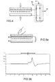
- FIG. 5A-5C illustrate a test of the previously described triboelectric generator in which the polymer dielectric layer 15 is placed in contact with the dielectric material 25 of the support 21 by applying a finger to the first support 11 (FIG. Figure 5A ).
- the contacting is such that the contact area between the materials 15 and 25 may for example be of the order of 2.5 cm * 2.5 cm.
- the pressure exerted on the first support 11 is then released and an electrical signal is visualized ( Figure 5B ) generated by tribo-electric effect at the output of the generator for example using an oscilloscope having an input impedance for example of the order of 1 M ⁇ .
- the Figure 5C gives an example of an electrical signal generated across the capacitor 32 at the output of the rectifier bridge 31. Due to the conical shape of the tips of the triboelectric generator, it is possible to obtain a tribo-electric signal of large amplitude.
- the porous dielectric material 15 having conical microstructures 17 may be brought into direct contact with an electrode to generate electrostatic charges.
- the figure 6 illustrates a particular embodiment of such an alternative wherein the rough dielectric porous material is intended to be contacted with a conductive electrode layer formed of a rough conductive material 42.
- This rough conductive material 42 is a material whose electrical resistivity decreases when the temperature increases such as for example graphene.
- the generator When the generator is operated to friction the graphene-based rough conductive layer 42 and the rough dielectric porous material having tribo-electric properties different from those of graphene, the electrical conductivity of the graphene is increased. allows to increase the electric signal generated by tribo-electric effect.
- a particular application of a triboelectric generator according to one or the other of the examples previously described concerns the measurement of humidity. It is thus possible to integrate the triboelectric generator into a humidity sensor.
- the humidity within the sensor is capable of varying the friction between the layer 14 of rough dielectric material with conical micro-tips and another layer having different tribo-electric properties.
Landscapes
- Physics & Mathematics (AREA)
- Engineering & Computer Science (AREA)
- Plasma & Fusion (AREA)
- Treatments Of Macromolecular Shaped Articles (AREA)
Abstract

Description
- La présente invention concerne le domaine des générateurs à effet tribo-électrique et leur fabrication.
- Elle prévoit notamment de réaliser un générateur triboélectrique doté d'au moins un élément comportant une couche de matériau polymère diélectrique à surface rugueuse, sans nécessairement devoir utiliser un moule pour créer ou modifier la rugosité de la surface de cette couche de matériau diélectrique.
- Le fonctionnement d'un générateur tribo-électrique repose sur une mise en contact d'un premier matériau et d'un deuxième matériau de natures différentes, un premier matériau ayant tendance à céder des électrons, le deuxième matériau ayant de préférence tendance à capter des électrons. En mettant en contact des matériaux de propriétés triboélectriques différentes on créé un transfert de charges entre ces deux matériaux qui peut être traduit sous forme d'une différence de potentiels ou d'un courant. L'effet triboélectrique peut être augmenté en frottant les matériaux l'un contre l'autre.
- Pour fabriquer un générateur tribo-électrique, il est connu d'utiliser une couche de matériau polymère que l'on structure pour créer en surface une rugosité importante et pouvoir ainsi augmenter le phénomène de friction.
- Les documents
US 2013/0049531 A1 et « Transparent Triboelectric Nano-generators and Self-Powered Pressure Sensors Based on Micropatterned Plastic Films », Feng-Ru Fan et al., Nano Letters 2012, 12, 3109-3114 présentent un procédé de réalisation d'un générateur à effet triboélectrique comprenant une couche de polydimethylsiloxane (PDMS) à surface rugueuse, dont la rugosité est formée par création de motifs sous forme de rainures, ou bien de cubes, ou encore de pyramides, à l'aide d'un moule. - Un tel procédé nécessite un remplissage du moule par du PDMS, et surtout une étape délicate de retrait du PDMS structuré du moule sans le détériorer. Le retrait du PDMS peut par ailleurs avoir pour inconvénient de nécessiter l'utilisation d'un surfactant.
- Il se pose le problème de trouver un nouveau procédé de réalisation d'un générateur à effet tribo-électrique doté d'au moins une couche de matériau polymère rugueuse et qui ne nécessite pas l'utilisation d'un moule.
- Selon un mode de réalisation, la présente invention concerne tout d'abord un procédé de réalisation d'un élément d'un générateur à effet triboélectrique comprenant des étapes consistant à :
- a) former sur un support une couche à base d'un matériau à base d'un polymère diélectrique donné,
- b) effectuer au moins un traitement thermique sur le matériau polymère diélectrique donné de manière à cristalliser le matériau polymère diélectrique donné et générer des structures en forme de micro-pointes, en particulier coniques, en surface du matériau polymère diélectrique donné.
- Le matériau polymère diélectrique donné peut être choisi de manière à avoir une constante diélectrique élevée, de préférence telle que εr > 30 (εr étant la permittivité relative du matériau diélectrique).
- Le matériau polymère diélectrique donné est avantageusement un matériau hydrophobe.
- Le matériau polymère diélectrique donné peut être ainsi doté d'un groupement fluoré, par exemple un groupement de polyfluorure de vinylidène (PVDF).
- Avantageusement, le matériau polymère diélectrique donné peut être un terpolymère tel que le P(VDF-TrFe-CFE) ou le P(VDF-TrFe-CTFE) ou un mélange de P(VDF-TrFe-CFE) et de P(VDF-TrFe-CTFE). D'autres polymères à base de PVDF comme les copolymères P(VDF-TrFe) peuvent être utilisés.
- Le matériau polymère formé à l'étape a) peut être sous forme d'une matrice polymère comportant un additif, choisi de manière à avoir une vitesse de transition supérieure à celle du polymère diélectrique donné.
- On entend par « transition » une modification structurale sous l'effet de la variation d'un paramètre extérieur, ici la température.
- L'additif peut être choisi de sorte à avoir une température de changement de sa structuration inférieure à celle du polymère donné et de sorte que lorsqu'on effectue le traitement thermique de cristallisation, une modification structurale (cristallisation) de la matrice de polymère entraine une mise en contrainte de cet additif.
- Cette contrainte mécanique fait ressortir des structures sous forme de micro-pointes en particulier de forme coniques.
- L'étape b) de traitement thermique peut être un recuit photonique comprenant une exposition de la couche de matériau polymère à au moins une impulsion lumineuse de rayonnement UV encore appelé flash UV. Un tel traitement a notamment pour avantage d'être rapide à réaliser et de permettre de modifier le matériau polymère diélectrique principalement en surface.
- L'additif utilisé à l'étape a) peut être alors avantageusement un composé absorbant le rayonnement UV tel que du Pyrène.
- Un tel additif peut permettre de favoriser le développement d'une surface rugueuse sur le matériau polymère diélectrique lors de l'étape b).
- Selon une possibilité de mise en oeuvre, le support peut être un support flexible à base de matériau polymère.
- Un mode de réalisation de la présente invention prévoit un procédé de fabrication d'un générateur à effet triboélectrique comprenant un premier élément destiné à être mis en contact avec un deuxième élément afin de créer des charges électriques, le procédé comprenant des étapes consistant à :
- effectuer un procédé tel que défini précédemment pour former le premier élément,
- former une couche à base de Graphène sur un deuxième support pour réaliser le deuxième élément.
- Le Graphène a pour avantage d'être un matériau conducteur rugueux propice à générer des frottements et dont la conductivité électrique augmente avec la température, celle-ci étant susceptible d'augmenter lorsque les frottements augmentent.
- L'invention concerne, selon un autre aspect, un générateur triboélectrique mis en oeuvre à l'aide d'un procédé tel que défini précédemment.
- L'invention concerne ainsi également un générateur triboélectrique pour créer des charges électriques par mise en contact entre un premier élément et un deuxième élément, le premier élément comprenant une couche conductrice revêtue d'un matériau diélectrique polymère rugueux comportant des micro-pointes de forme conique.
- Le matériau polymère diélectrique donné peut être un matériau diélectrique à constante diélectrique élevée, en particulier telle que εr > 30 (εr étant la permittivité relative du matériau diélectrique).
- Un matériau diélectrique à constante diélectrique élevée permet de générer un courant triboélectrique plus important, en particulier dans le cas où la friction (génération de température aux interfaces) fait augmenter sa constante diélectrique.
- Le matériau polymère diélectrique donné peut être avantageusement un matériau hydrophobe.
- En prévoyant un matériau polymère hydrophobe, on réduit l'humidité au niveau de la surface rugueuse de ce matériau entrant en contact avec un autre élément pour générer des charges électriques. On évite ainsi de réduire la friction au niveau de la surface de contact rugueuse ce qui permet d'avoir une meilleure production d'énergie électrique.
- Le matériau polymère diélectrique donné peut comprendre un terpolymère, en particulier à base de PVDF tel que le P(VDF-TrFe-CFE) ou le P(VDF-TrFe-CTFE) ou un mélange de P(VDF-TrFe-CFE) et de P(VDF-TrFe-CTFE). On peut également utiliser un copolymère à base de PVDF tel que le P(VDF-TrFe).
- Le deuxième élément peut être avantageusement revêtu de Graphène.
- Un mode de réalisation de l'invention prévoit également un capteur d'humidité comprenant un générateur triboélectrique tel que défini plus haut.
- La présente invention sera mieux comprise à la lecture de la description d'exemples de réalisation donnés, à titre purement indicatif et nullement limitatif, en faisant référence aux dessins annexés sur lesquels :
- les
figures 1A-1C illustrent un exemple de procédé selon un mode de réalisation de l'invention pour mettre en oeuvre un élément d'un générateur tribo-électrique, cet élément comprenant un matériau polymère diélectrique sur lequel on crée une surface rugueuse sous forme de micro-pointes coniques en modifiant par traitement thermique la structure du matériau diélectrique du polymère ; - la
figure 2 illustre une réalisation d'un autre élément de générateur tribo-électrique destiné à être mis en contact avec un élément tel qu'illustré par exemple sur lesfigures 1A-1C ; - la
figure 3 illustre une surface rugueuse dotée de micro-pointes coniques sur un matériau polymère diélectrique tel que mis en oeuvre dans un générateur tribo-électrique suivant l'invention ; - la
figure 4 illustre un exemple de dispositif suivant l'invention comprenant générateur tribo-électrique associé à un circuit de récupération et de stockage d'énergie électrique produite par le générateur; - les
figures 5A-5C illustrent un test électrique d'un générateur tribo-électrique ; - la
figure 6 illustre une variante de générateur tribo-électrique doté d'une couche de graphène destinée à être mise en contact avec un matériau polymère diélectrique rugueux afin d'améliorer la génération des charges électriques ; - Des parties identiques, similaires ou équivalentes des différentes figures portent les mêmes références numériques de façon à faciliter le passage d'une figure à l'autre.
- Les différentes parties représentées sur les figures ne le sont pas nécessairement selon une échelle uniforme, pour rendre les figures plus lisibles.
- Un exemple de procédé de réalisation d'un élément de générateur triboélectrique va à présent être donné en liaison avec les
figures 1A-1C . - Le matériau de départ de ce procédé peut être un support 11 dont la composition et l'épaisseur sont prévus de manière à le rendre flexible.
- Le support 11 peut être formé d'une couche de matériau polymère, par exemple tel que du polynaphtalate d'éthylène (PEN) ou du Polytéréphtalate d'éthylène (PET), ou de polyimide (PI), ou de poly-éther-éther-cétone (PEEK), ou un substrat en papier cellulose et avoir une épaisseur qui peut être par exemple comprise entre 5 µm et 200 µm, par exemple de l'ordre de 25 µm.
- Sur le support 11, on dépose tout d'abord une couche conductrice 12 (
figure 1A ), destinée à former une première électrode. La couche conductrice peut être formée par exemple par dépôt physique en phase vapeur (PVD) ou par jet d'encre, ou par sérigraphie, ou par pulvérisation assistée par ultrason (« ultrasonic spray coating » selon la terminologie anglo-saxonne). - La couche conductrice 12 peut être par exemple à base d'un matériau métallique tel que l'argent (Ag), le platine (Pt), l'aluminium (Al), le cuivre (Cu), l'or (Au), le titane (Ti),l'Indium Tin Oxide (ITO), ou de nano-fils, par exemple à base d'argent, et peut avoir une épaisseur comprise par exemple entre 10 nm et 1 µm. Selon un exemple de réalisation particulier, la couche métallique 12 est une couche à base d'or de 30 nm d'épaisseur.
- Ensuite, on forme une couche 14 à base d'un matériau polymère diélectrique 15 (
figure 1B ) sur la couche métallique 12. La couche de matériau polymère diélectrique 15 a une épaisseur qui peut être comprise par exemple entre 100 nm et 20 µm. Le matériau polymère diélectrique 15 est choisi de préférence de manière à avoir une constante diélectrique élevée, en particulier telle que εr > 30, et de préférence susceptible de varier en fonction de la température à laquelle est placée ce matériau. Le matériau polymère diélectrique 15 peut être également choisi de manière à avoir des propriétés hydrophobes. Pour répondre à ces critères, le matériau polymère diélectrique 15 choisi peut être par exemple à base d'un terpolymère comprenant un groupement fluoré, en particulier à base de polyfluorure de vinylidène (PVDF). - Selon des exemples de réalisations particuliers, le matériau polymère diélectrique 15 peut être du P(VDF-TrFe-CFE), ou du P(VDF-TrFe-CTFE), ou un composé à base de P(VDF-TrFe-CFE) et de P(VDF-TrFe-CTFE). Selon un autre exemple, le matériau polymère diélectrique 15 peut être un copolymère à base de PVDF comme par exemple du P(VDF-TrFe).
- Préalablement à son dépôt, le matériau polymère diélectrique 15 peut être préparé sous forme d'un mélange d'une première solution à base d'un terpolymère tel que du P(VDF-TrFe), ou du P(VDF-TrFe-CTFE), ou du P(VDF-TrFe-CFE), ou du P(VDF-TrFe) et du P(VDF-TrFe-CTFE) mélangés, et d'une deuxième solution comprenant un additif ayant une température de transition, en particulier de cristallisation inférieure à celle du polymère donné. L'additif choisi peut être par exemple du Pyrène (C16H10).
- La première solution peut être réalisée par introduction d'une poudre à base de P(VDF-TrFe-CFE) et/ou de P(VDF-TrFe-CTFE) que l'on dissout dans un solvant tel que par exemple du cyclopentanone, du diméthylformamide ou du diméthylacétamide.
- La proportion de terpolymère dans son solvant peut varier en poids par exemple de 1% à 20%.
- La deuxième solution peut être réalisée par introduction de grains solides de Pyrène que l'on dissout dans un solvant tel que par exemple de l'acétone de sorte à avoir une proportion en poids de Pyrène qui peut être par exemple comprise entre 5% et 40%.
- La proportion de terpolymère dans le mélange conditionne notamment la viscosité de la solution de dépôt, celle-ci pouvant être adaptée en fonction du type de technique de dépôt que l'on souhaite utiliser. Par exemple, lorsqu'on souhaite réaliser un dépôt par sérigraphie on peut mettre en oeuvre une solution ayant une viscosité importante, ce en prévoyant une concentration importante en terpolymère dans son solvant. Selon un autre exemple, lorsqu'on souhaite réaliser un dépôt à la tournette (« spin coating » selon la terminologie anglo-saxonne) une solution de viscosité plus faible et donc ayant une concentration en terpolymère plus faible est mise en oeuvre.
- La solution de dépôt peut être composée, au final, de 3% à 40% en poids de la deuxième solution dans la première solution. Le mélange final est remué à une température qui peut être comprise par exemple entre 30 °C et 45 °C.
- Le dépôt de la solution de terpolymère est ensuite suivi d'au moins une étape de recuit thermique dit « de cristallisation », afin de modifier la structure du matériau polymère et augmenter la rugosité de sa surface. Un recuit thermique ou une successions de recuits à une température supérieure à la température de cristallisation du matériau polymère peut être réalisée.
- On peut effectuer par exemple un premier recuit à une température qui peut être comprise par exemple entre 90 et 100°C et selon une durée qui peut être comprise par exemple entre 5 et 30 min. Un exemple particulier de mise en oeuvre prévoit de réaliser le premier recuit thermique à une température de l'ordre de 100°C pendant une durée de 5 minutes.
- Ensuite, un deuxième recuit est effectué à une température qui peut être comprise par exemple entre 110 et 130 °C et selon une durée par exemple comprise entre 5 et 30 min. Ce deuxième recuit peut permettre d'améliorer la cristallisation du Polymère. Un exemple particulier de mise en oeuvre prévoit de réaliser le deuxième recuit thermique à une température de l'ordre de 115°C pendant une durée de 30 minutes.
- Lors du ou des recuits, du fait de la vitesse de cristallisation plus élevée de la matrice de polymères, la structure de l'additif choisi, par exemple choisi parmi le Pyrène, le Polystyrène et un mélange de Polystyrène et de Pyrène, se modifie structurellement sur la surface à cause des contraintes mécaniques exercées par la cristallisation du matériau polymère diélectrique.
- Les inventeurs ont constatés que, de manière surprenante, cette mise en contrainte se traduisait par l'apparition de microstructures ou micro-pointes 17 coniques, c'est à dire en forme de cône de révolution. Le traitement thermique du matériau polymère permet ainsi de favoriser la formation d'une rugosité importante sur la couche 12 (
figure 1C ). - L'apparition des micro-pointes coniques est conditionnée notamment par le choix en termes de vitesses respectives de cristallisation et de l'apparition de contraintes mécaniques sur la surface du terpolymère et de l'additif, et des conditions (temps, température) de recuit thermique. Une vitesse cristallisation du terpolymere ou du copolymère adéquate permet de contraindre mécaniquement l'additif au niveau de la surface et crée des microstructure sous forme de pointes.
- La taille des micro-pointes 17 est quant à elle conditionnée notamment par la proportion en matériau terpolymère dans la solution de dépôt.
- Les micro-pointes 17 obtenues peuvent avoir une base de diamètre D1 (mesuré dans une direction parallèle au plan [0 ;x ;y] du repère orthogonal [0 ;x ;y ;z] sur la
figure 1C ) compris par exemple entre 2 µm et 10 µm, de l'ordre de plusieurs micromètres et une hauteur H1 (mesurée dans une direction orthogonale au plan [0 ;x ;y] sur lafigure 1C ) compris par exemple entre 200 nm et 5 µm. - En remplacement du recuit thermique, on peut effectuer un recuit photonique pour cristalliser le matériau polymère 15 et faire apparaitre des micro-pointes 17 sur sa surface.
- Le recuit photonique peut comprendre une exposition très brève, i.e. comprise entre plusieurs µs et plusieurs ms, à un rayonnement UV. Une impulsion UV encore appelé flash UV d'une durée par exemple comprise entre 1 ms et 2 ms, et selon une fluence comprise par exemple entre 15 J/cm2 et 50 J/cm2 peut être mise en oeuvre pour réaliser ce recuit photonique.
- Un exemple particulier prévoit l'exposition au rayonnement pulsé UV avec une durée d'impulsion (également appelée « pulse ») de 2ms et une fluence de 17 J/cm2 lorsque la couche de matériau polymère a une épaisseur de l'ordre de 2 µm.
- La
figure 3 donne une image obtenue par microscope électronique à balayage de la face supérieure d'une couche polymère formée à partir d'un mélange de PVDF et de Pyrène après un traitement thermique tel que décrit précédemment et conduisant à la formation de micro-pointes 17 coniques. - Pour pouvoir générer des charges électrostatiques, la couche 14 de matériau polymère diélectrique 15 à surface rugueuse et revêtue de micro-pointes 17 est destinée à être mise en contact avec un autre élément doté d'une électrode.
- Un exemple de réalisation de cet autre élément est donné sur la
figure 2 et comprend un deuxième support 21 destiné à être mis en contact avec la couche de matériau polymère diélectrique 15 à surface rugueuse. Le deuxième support 21 est formé à base d'un matériau donné présentant des caractéristiques triboélectriques différentes de celles du matériau polymère diélectrique 15 reposant sur le premier support 11. - Le deuxième support 21 peut être par exemple à base d'un matériau diélectrique 25, qui peut être polymère et semblable au matériau du premier support 11.
- Le matériau diélectrique 25 du deuxième support 21 peut être ainsi par exemple du polynaphtalate d'éthylène (PEN) ou du Polytéréphtalate d'éthylène (PET), ou un polyimide (PI), ou du poly-éther-éther-cétone (PEEK), ou du papier cellulose et avoir une épaisseur qui peut être par exemple comprise entre 5 µm et 200 µm, par exemple de l'ordre de 25 µm. Ainsi, le deuxième support 21 peut également avoir une composition et une épaisseur prévues de manière à le rendre flexible.
- Sur le deuxième support 21, une couche conductrice 22, qui peut être métallique, forme une deuxième électrode. La couche conductrice 22 peut être avantageusement réalisée en même temps que celle formée sur le premier support 11.
- La
figure 4 illustre le générateur tribo-électrique réalisé précédemment associé à un circuit de récupération d'énergie électrique. - Un actionnement du générateur triboélectrique peut être effectué en exerçant une pression sur le premier support 11 et/ou sur le deuxième support 21, de manière à mettre en contact la surface rugueuse de la couche 14 de matériau polymère diélectrique 15 dotée de micro-pointes 17 coniques avec le matériau diélectrique 25 du support 21.
- La rugosité du matériau polymère diélectrique 15 à l'aide des micro-pointes de forme conique permet d'obtenir un bon coefficient de friction avec le matériau diélectrique 25. Au moment de la friction entre les matériaux 15 et 25 ayant des propriétés triboélectriques différentes, et en particulier des aptitudes différentes à céder ou accepter des électrons, un échauffement local dû aux frottements fait varier la constante diélectrique et donc la capacitance électrique du système et par conséquent le signal électrique généré par effet triboélectrique par le générateur.
- Le circuit de récupération d'énergie électrique est connecté aux couches conductrices 12, 22 collectrices de charges et peut comprendre un moyen redresseur 31 pour redresser un signal électrique produit par le générateur, ainsi qu'un moyen de stockage 32 de charges électriques, par exemple sous forme d'un capacité en sortie du moyen redresseur 31 permettant d'emmagasiner l'énergie électrique produite par le générateur. Le redresseur 31 est par exemple formé d'un pont de 4 diodes.
- Les
figures 5A-5C , illustrent un test du générateur triboélectrique précédemment décrit lors duquel on met en contact la couche diélectrique polymère 15 et le matériau diélectrique 25 du support 21 en appliquant un doigt sur le premier support 11 (figure 5A ). La mise en contact est telle que la surface de contact entre les matériaux 15 et 25 peut être par exemple de l'ordre de 2.5 cm*2.5 cm. On relâche ensuite la pression exercée sur le premier support 11 et on visualise un signal électrique (figure 5B ) généré par effet tribo-électrique en sortie du générateur par exemple en utilisant un oscilloscope ayant une impédance d'entrée par exemple de l'ordre de 1 MΩ. - La
figure 5C donne un exemple de signal électrique généré aux bornes de la capacité 32 en sortie du pont redresseur 31. De par la forme conique des pointes du générateur tribo-électrique, on peut obtenir un signal tribo-électrique d'amplitude importante. - Selon une variante de mise en oeuvre du générateur tribo-électrique, le matériau poreux diélectrique 15 comportant des micro-structures coniques 17, peut être mis en contact directement avec une électrode pour générer des charges électrostatiques.
- La
figure 6 illustre un exemple de réalisation particulier d'une telle variante dans laquelle le matériau poreux diélectrique 15 rugueux est destiné à être mis en contact avec une couche conductrice servant d'électrode et formée d'un matériau conducteur rugueux 42. Ce matériau conducteur rugueux 42 est un matériau dont la résistivité électrique diminue lorsque la température augmente tel que par exemple du Graphène. - Lorsqu'on actionne le générateur de manière à mettre en friction la couche conductrice rugueuse 42 à base de Graphène et le matériau poreux diélectrique 15 rugueux ayant des propriétés tribo-électriques différentes de celles du Graphène, on augmente la conductivité électrique du Graphène, ce qui permet d'augmenter le signal électrique généré par effet tribo-électrique.
- Une application particulière d'un générateur triboélectrique selon l'un ou l'autre des exemples précédemment décrits concerne la mesure d'humidité. On peut ainsi prévoir d'intégrer le générateur à effet tribo-électrique dans un capteur d'humidité.
- L'humidité au sein du capteur est susceptible de faire varier le frottement entre la couche 14 de matériau polymère diélectrique 15 rugueux à micro-pointes coniques et une autre couche ayant des propriétés tribo-électriques différentes.
- Ainsi, suivant l'humidité du milieu dans lequel se trouve le capteur on peut obtenir en sortie du générateur, pour une même force d'actionnement permettant de provoquer une mise en contact de ses éléments, différents niveaux de signaux en sortie du générateur à effet tribo-électrique.
Claims (14)
- Procédé de réalisation d'un élément de générateur triboélectrique comportant un matériau à base de polymère diélectrique rugueux destiné, pour créer des charges électriques, à être mis en contact avec un autre matériau ayant des propriétés triboélectriques différentes de celles du matériau polymère diélectrique, le procédé comprenant des étapes consistant à :a) former sur un support (11) une couche (14) à base d'un matériau formé d'un polymère diélectrique donné (15),b) effectuer au moins traitement thermique de manière à cristalliser le matériau polymère diélectrique donné et former des structures en forme de micro-pointes en surface du matériau polymère diélectrique donné.
- Procédé selon la revendication 1, dans lequel le matériau polymère diélectrique donné comprend un terpolymère ou un copolymère à base de PVDF.
- Procédé selon la revendication 1 ou 2, dans lequel le matériau polymère diélectrique donné est hydrophobe.
- Procédé selon la revendication 2 ou 3, dans lequel le matériau polymère diélectrique donné est à base à base de polyfluorure de vinylidène (PVDF), en particulier à base de P(VDF-TrFe-CFE) et/ou de P(VDF-TrFe-CTFE) ou du P(VDF-TrFe).
- Procédé selon l'une des revendications 1 à 4, dans lequel le matériau polymère formé à l'étape a) est mélangé à un additif de sorte que, la cristallisation du matériau polymère diélectrique conduit à l'exercice de contraintes mécaniques sur l'additif et favorise l'apparition de structures en forme de micro-pointes sur la surface.
- Procédé selon l'une des revendications 5, dans lequel l'additif est un composé absorbant le rayonnement UV tel que du Pyrène.
- Procédé selon l'une des revendications 1 à 6, dans lequel l'étape b) de traitement thermique comprend un recuit photonique par exposition de la couche de matériau polymère à au moins une impulsion lumineuse de rayonnement UV.
- Procédé selon l'une des revendications 1 à 7 dans lequel le support est un support flexible à base de matériau polymère.
- Procédé de fabrication d'un générateur à effet triboélectrique comprenant un premier élément destiné à être mis en contact avec un deuxième élément pour créer des charges électriques, le procédé comprenant des étapes consistant à :- effectuer procédé suivant l'une des revendications 1 à 7 pour former le premier élément,- former une couche à base de Graphène sur un deuxième support (21) pour réaliser le deuxième élément.
- Générateur triboélectrique comprenant un premier élément et un deuxième élément, le générateur étant apte à créer des charges électriques par effet tribo-électrique par mise en contact entre le premier élément et le deuxième élément, le premier élément comprenant une couche conductrice revêtue d'un matériau diélectrique polymère rugueux comportant des micro-pointes de forme conique.
- Générateur triboélectrique selon la revendication 10, dans lequel le matériau polymère diélectrique donné a une permittivité relative εr > 30.
- Générateur triboélectrique selon la revendication 10 ou 11, dans lequel le matériau polymère diélectrique donné est hydrophobe.
- Générateur triboélectrique selon l'une des revendications 11 ou 12, dans lequel le matériau polymère diélectrique donné est à base d'un terpolymère tel que du P(VDF-TrFe-CFE) et/ou du P(VDF-TrFe-CTFE), ou un copolymère comme le P(VDF-TrFe).
- Capteur d'humidité comprenant un générateur triboélectrique selon l'une des revendications 10 à 13.
Applications Claiming Priority (1)
| Application Number | Priority Date | Filing Date | Title |
|---|---|---|---|
| FR1457138A FR3024303B1 (fr) | 2014-07-24 | 2014-07-24 | Procede ameliore de realisation d'un generateur tribo-electrique a polymere dielectrique rugueux |
Publications (2)
| Publication Number | Publication Date |
|---|---|
| EP2978123A1 true EP2978123A1 (fr) | 2016-01-27 |
| EP2978123B1 EP2978123B1 (fr) | 2019-05-08 |
Family
ID=52102759
Family Applications (1)
| Application Number | Title | Priority Date | Filing Date |
|---|---|---|---|
| EP15177468.4A Not-in-force EP2978123B1 (fr) | 2014-07-24 | 2015-07-20 | Procede de realisation d'un generateur tribo -electrique a polymere dielectrique rugueux |
Country Status (3)
| Country | Link |
|---|---|
| US (1) | US10498259B2 (fr) |
| EP (1) | EP2978123B1 (fr) |
| FR (1) | FR3024303B1 (fr) |
Cited By (1)
| Publication number | Priority date | Publication date | Assignee | Title |
|---|---|---|---|---|
| WO2020016534A1 (fr) * | 2018-07-20 | 2020-01-23 | Commissariat A L'energie Atomique Et Aux Energies Alternatives | Dispositif electronique comprenant une structure antireflet |
Families Citing this family (21)
| Publication number | Priority date | Publication date | Assignee | Title |
|---|---|---|---|---|
| US9394875B2 (en) * | 2014-08-05 | 2016-07-19 | Georgia Tech Research Corporation | System for harvesting water wave energy |
| CN104811089A (zh) * | 2015-05-19 | 2015-07-29 | 京东方科技集团股份有限公司 | 一种摩擦生电装置及其制作方法、电子设备和可穿戴设备 |
| US10425018B2 (en) * | 2015-05-19 | 2019-09-24 | Georgia Tech Research Corporation | Triboelectric nanogenerator for harvesting broadband kinetic impact energy |
| CN105207517B (zh) * | 2015-08-26 | 2017-08-25 | 京东方科技集团股份有限公司 | 摩擦发电装置及其制造方法 |
| EP3228240A1 (fr) * | 2016-04-08 | 2017-10-11 | Koninklijke Philips N.V. | Capteur de qualité de fibres |
| US10770990B2 (en) | 2016-05-10 | 2020-09-08 | Samsung Electronics Co., Ltd. | Triboelectric generator |
| KR102578823B1 (ko) | 2016-05-10 | 2023-09-15 | 삼성전자주식회사 | 마찰전기 발전기 |
| US10277147B2 (en) * | 2016-06-09 | 2019-04-30 | Wisconsin Alumni Research Foundation | Triboelectric nanogenerators based on chemically treated cellulose |
| US10749447B2 (en) * | 2016-11-03 | 2020-08-18 | City University Of Hong Kong | Electrical apparatus and a method for fabricating an electrical apparatus |
| WO2018226162A1 (fr) * | 2017-06-07 | 2018-12-13 | Nanyang Technological University | Nanofibres noyau-enveloppe pour des applications triboélectriques et de détection capacitive |
| EP3639307B1 (fr) | 2017-06-16 | 2022-03-23 | Carrier Corporation | Système de transfert de chaleur électrocalorique comprenant des copolymères |
| LU100485B1 (en) | 2017-10-19 | 2019-04-25 | Luxembourg Inst Science & Tech List | Triboelectric member with embossed honeycomb pattern |
| KR102213229B1 (ko) * | 2017-11-22 | 2021-02-04 | 송찰스기석 | 마찰전기 발전 소자 및 그 제조방법 |
| DE102018221053A1 (de) | 2018-04-05 | 2019-10-10 | Continental Reifen Deutschland Gmbh | Vorrichtung zum Messen einer mechanischen Kraft, umfassend eine erste, zweite, dritte, vierte und fünfte Schicht sowie die Verwendungen der Vorrichtung und Reifen oder technischer Gummiartikel umfassend die Vorrichtung |
| KR20200021147A (ko) * | 2018-08-20 | 2020-02-28 | 경희대학교 산학협력단 | 층상 정전 발전기 및 제조방법 |
| FR3089291B1 (fr) | 2018-11-29 | 2023-03-24 | Commissariat Energie Atomique | Structure de détection de rayonnement électromagnétique à absorption optimisée et procédé de formation d’une telle structure |
| FR3090098B1 (fr) | 2018-12-13 | 2021-11-26 | Commissariat Energie Atomique | Procédé de fabrication d'une structure de détection à taux d'absorption optimisé et ladite structure |
| EP3742143A1 (fr) * | 2019-05-20 | 2020-11-25 | SABIC Global Technologies B.V. | Capteur d'impact triboélectrique et applications pour son utilisation |
| US12091313B2 (en) | 2019-08-26 | 2024-09-17 | The Research Foundation For The State University Of New York | Electrodynamically levitated actuator |
| CA3178883A1 (fr) | 2020-06-30 | 2022-01-06 | Novocure Gmbh | Reseaux de transducteurs flexibles dotes d'une couche polymere isolante permettant l'application de champs de traitement des tumeurs (ttfields) |
| US11784587B2 (en) | 2021-01-07 | 2023-10-10 | City University Of Hong Kong | Electronic sensing apparatus and a method of producing the electronic sensing apparatus |
Citations (1)
| Publication number | Priority date | Publication date | Assignee | Title |
|---|---|---|---|---|
| US20130049531A1 (en) | 2011-08-30 | 2013-02-28 | Georgia Tech Research Corporation | Triboelectric Generator |
Family Cites Families (6)
| Publication number | Priority date | Publication date | Assignee | Title |
|---|---|---|---|---|
| US8999200B2 (en) * | 2002-07-23 | 2015-04-07 | Sabic Global Technologies B.V. | Conductive thermoplastic composites and methods of making |
| NO324539B1 (no) * | 2005-06-14 | 2007-11-19 | Thin Film Electronics Asa | Fremgangsmate i fabrikasjonen av en ferroelektrisk minneinnretning |
| US20080021328A1 (en) * | 2006-07-20 | 2008-01-24 | Konica Minolta Medical & Graphic, Inc. | Ultrasound probe and method of manufacturing ultrasound probe |
| FR2991456B1 (fr) | 2012-06-04 | 2023-02-10 | Commissariat Energie Atomique | Capteur d'humidite capacitif a electrode de graphene |
| US9595894B2 (en) * | 2012-09-21 | 2017-03-14 | Georgia Tech Research Corporation | Triboelectric nanogenerator for powering portable electronics |
| US8519596B1 (en) * | 2013-01-23 | 2013-08-27 | K-Technology Usa, Inc. | Graphene triboelectric charging device and a method of generating electricity by the same |
-
2014
- 2014-07-24 FR FR1457138A patent/FR3024303B1/fr not_active Expired - Fee Related
-
2015
- 2015-07-20 EP EP15177468.4A patent/EP2978123B1/fr not_active Not-in-force
- 2015-07-20 US US14/803,429 patent/US10498259B2/en not_active Expired - Fee Related
Patent Citations (1)
| Publication number | Priority date | Publication date | Assignee | Title |
|---|---|---|---|---|
| US20130049531A1 (en) | 2011-08-30 | 2013-02-28 | Georgia Tech Research Corporation | Triboelectric Generator |
Non-Patent Citations (1)
| Title |
|---|
| FENG-RU FAN ET AL.: "Transparent Triboelectric Nano-generators and Self-Powered Pressure Sensors Based on Micropatterned Plastic Films", NANO LETTERS, vol. 12, 2012, pages 3109 - 3114 |
Cited By (2)
| Publication number | Priority date | Publication date | Assignee | Title |
|---|---|---|---|---|
| WO2020016534A1 (fr) * | 2018-07-20 | 2020-01-23 | Commissariat A L'energie Atomique Et Aux Energies Alternatives | Dispositif electronique comprenant une structure antireflet |
| FR3084205A1 (fr) * | 2018-07-20 | 2020-01-24 | Commissariat A L'energie Atomique Et Aux Energies Alternatives | Dispositif electronique comprenant une structure antireflet |
Also Published As
| Publication number | Publication date |
|---|---|
| EP2978123B1 (fr) | 2019-05-08 |
| FR3024303B1 (fr) | 2016-08-26 |
| US20160028327A1 (en) | 2016-01-28 |
| US10498259B2 (en) | 2019-12-03 |
| FR3024303A1 (fr) | 2016-01-29 |
Similar Documents
| Publication | Publication Date | Title |
|---|---|---|
| EP2978123B1 (fr) | Procede de realisation d'un generateur tribo -electrique a polymere dielectrique rugueux | |
| EP2192635B1 (fr) | Procédé de fabrication d'un substrat nanostructuré pour OLED et procédé de fabrication d'une OLED avec le substrat nanostructuré | |
| EP1543080B1 (fr) | Procede de garniture d une surface par un film organique | |
| FR2977713A1 (fr) | Electrode transparente conductrice multicouche et procede de fabrication associe | |
| EP3069438B1 (fr) | Systeme de conversion d'energie thermique et/ou mecanique en energie electrique | |
| CN102460618A (zh) | 离子聚合物金属复合电容器 | |
| EP2836896A1 (fr) | Capteur tactile et procede de fabrication d'un tel capteur | |
| FR2996359A1 (fr) | Electrode transparente conductrice et procede de fabrication associe | |
| EP3492892A1 (fr) | Capteur de motif thermique a capacite pyroelectrique | |
| EP3579151B1 (fr) | Procede de fabrication d'un calculateur a reseaux de neurones recurrents | |
| EP3028855B1 (fr) | Procédé de fabrication d'un composant comportant un empilement d'une couche fonctionnelle sur un film composite | |
| FR3092950A1 (fr) | Générateur triboélectrique | |
| EP3127173B1 (fr) | Actionneur électroactif et procédé de réalisation | |
| EP3492894A1 (fr) | Capteur de motif thermique a capacite pyroelectrique | |
| EP3336904A1 (fr) | Procédé de fabrication d'un module photovoltaïque et module photovoltaïque ainsi obtenu | |
| FR3066768A1 (fr) | Procede de preparation d’une membrane conductrice, transparente et flexible. | |
| EP3688674B1 (fr) | Procede de fabrication d'un calculateur a reseaux de neurones recurrents | |
| FR3093658A1 (fr) | Procede pour deposer une couche en pvdf ou en un de ses copolymeres sur un substrat en verre ou en polymere | |
| FR3107989A1 (fr) | Capteur de motif thermique dont la couche de protection surfacique presente une conduction thermique anisotrope | |
| FR3078817A1 (fr) | Procede d'elaboration d'electrodes sur un substrat et les dispositifs comprenant lesdites electrodes | |
| FR3033552B1 (fr) | Procede de fabrication d'un micro-generateur mecano-electrique flexible et micro-generateur correspondant | |
| FR2962850A1 (fr) | Dispositif et procede pour former sur un nanofil en semi-conducteur un alliage de ce semi-conducteur avec un metal ou un metalloide. | |
| WO2024121513A1 (fr) | Dispositif piezoelectrique comprenant une matrice d'electrodes | |
| WO2010094883A1 (fr) | Dispositif et procede de detection de contrainte mecanique, procede de fabrication d'un tel dispositif, et calibration | |
| FR3093801A1 (fr) | Dispositif comprenant un substrat en verre ou en polymere recouvert par une couche en pvdf ou en un de ses copolymeres |
Legal Events
| Date | Code | Title | Description |
|---|---|---|---|
| PUAI | Public reference made under article 153(3) epc to a published international application that has entered the european phase |
Free format text: ORIGINAL CODE: 0009012 |
|
| AK | Designated contracting states |
Kind code of ref document: A1 Designated state(s): AL AT BE BG CH CY CZ DE DK EE ES FI FR GB GR HR HU IE IS IT LI LT LU LV MC MK MT NL NO PL PT RO RS SE SI SK SM TR |
|
| AX | Request for extension of the european patent |
Extension state: BA ME |
|
| 17P | Request for examination filed |
Effective date: 20160705 |
|
| RBV | Designated contracting states (corrected) |
Designated state(s): AL AT BE BG CH CY CZ DE DK EE ES FI FR GB GR HR HU IE IS IT LI LT LU LV MC MK MT NL NO PL PT RO RS SE SI SK SM TR |
|
| GRAP | Despatch of communication of intention to grant a patent |
Free format text: ORIGINAL CODE: EPIDOSNIGR1 |
|
| STAA | Information on the status of an ep patent application or granted ep patent |
Free format text: STATUS: GRANT OF PATENT IS INTENDED |
|
| INTG | Intention to grant announced |
Effective date: 20181019 |
|
| GRAS | Grant fee paid |
Free format text: ORIGINAL CODE: EPIDOSNIGR3 |
|
| GRAJ | Information related to disapproval of communication of intention to grant by the applicant or resumption of examination proceedings by the epo deleted |
Free format text: ORIGINAL CODE: EPIDOSDIGR1 |
|
| GRAL | Information related to payment of fee for publishing/printing deleted |
Free format text: ORIGINAL CODE: EPIDOSDIGR3 |
|
| STAA | Information on the status of an ep patent application or granted ep patent |
Free format text: STATUS: REQUEST FOR EXAMINATION WAS MADE |
|
| GRAR | Information related to intention to grant a patent recorded |
Free format text: ORIGINAL CODE: EPIDOSNIGR71 |
|
| STAA | Information on the status of an ep patent application or granted ep patent |
Free format text: STATUS: GRANT OF PATENT IS INTENDED |
|
| GRAA | (expected) grant |
Free format text: ORIGINAL CODE: 0009210 |
|
| STAA | Information on the status of an ep patent application or granted ep patent |
Free format text: STATUS: THE PATENT HAS BEEN GRANTED |
|
| INTC | Intention to grant announced (deleted) | ||
| INTG | Intention to grant announced |
Effective date: 20190328 |
|
| AK | Designated contracting states |
Kind code of ref document: B1 Designated state(s): AL AT BE BG CH CY CZ DE DK EE ES FI FR GB GR HR HU IE IS IT LI LT LU LV MC MK MT NL NO PL PT RO RS SE SI SK SM TR |
|
| REG | Reference to a national code |
Ref country code: GB Ref legal event code: FG4D Free format text: NOT ENGLISH |
|
| REG | Reference to a national code |
Ref country code: CH Ref legal event code: EP Ref country code: AT Ref legal event code: REF Ref document number: 1131775 Country of ref document: AT Kind code of ref document: T Effective date: 20190515 |
|
| REG | Reference to a national code |
Ref country code: DE Ref legal event code: R096 Ref document number: 602015029685 Country of ref document: DE Ref country code: IE Ref legal event code: FG4D Free format text: LANGUAGE OF EP DOCUMENT: FRENCH |
|
| REG | Reference to a national code |
Ref country code: NL Ref legal event code: MP Effective date: 20190508 |
|
| REG | Reference to a national code |
Ref country code: LT Ref legal event code: MG4D |
|
| PG25 | Lapsed in a contracting state [announced via postgrant information from national office to epo] |
Ref country code: ES Free format text: LAPSE BECAUSE OF FAILURE TO SUBMIT A TRANSLATION OF THE DESCRIPTION OR TO PAY THE FEE WITHIN THE PRESCRIBED TIME-LIMIT Effective date: 20190508 Ref country code: SE Free format text: LAPSE BECAUSE OF FAILURE TO SUBMIT A TRANSLATION OF THE DESCRIPTION OR TO PAY THE FEE WITHIN THE PRESCRIBED TIME-LIMIT Effective date: 20190508 Ref country code: PT Free format text: LAPSE BECAUSE OF FAILURE TO SUBMIT A TRANSLATION OF THE DESCRIPTION OR TO PAY THE FEE WITHIN THE PRESCRIBED TIME-LIMIT Effective date: 20190908 Ref country code: NL Free format text: LAPSE BECAUSE OF FAILURE TO SUBMIT A TRANSLATION OF THE DESCRIPTION OR TO PAY THE FEE WITHIN THE PRESCRIBED TIME-LIMIT Effective date: 20190508 Ref country code: AL Free format text: LAPSE BECAUSE OF FAILURE TO SUBMIT A TRANSLATION OF THE DESCRIPTION OR TO PAY THE FEE WITHIN THE PRESCRIBED TIME-LIMIT Effective date: 20190508 Ref country code: LT Free format text: LAPSE BECAUSE OF FAILURE TO SUBMIT A TRANSLATION OF THE DESCRIPTION OR TO PAY THE FEE WITHIN THE PRESCRIBED TIME-LIMIT Effective date: 20190508 Ref country code: HR Free format text: LAPSE BECAUSE OF FAILURE TO SUBMIT A TRANSLATION OF THE DESCRIPTION OR TO PAY THE FEE WITHIN THE PRESCRIBED TIME-LIMIT Effective date: 20190508 Ref country code: NO Free format text: LAPSE BECAUSE OF FAILURE TO SUBMIT A TRANSLATION OF THE DESCRIPTION OR TO PAY THE FEE WITHIN THE PRESCRIBED TIME-LIMIT Effective date: 20190808 Ref country code: FI Free format text: LAPSE BECAUSE OF FAILURE TO SUBMIT A TRANSLATION OF THE DESCRIPTION OR TO PAY THE FEE WITHIN THE PRESCRIBED TIME-LIMIT Effective date: 20190508 |
|
| PG25 | Lapsed in a contracting state [announced via postgrant information from national office to epo] |
Ref country code: GR Free format text: LAPSE BECAUSE OF FAILURE TO SUBMIT A TRANSLATION OF THE DESCRIPTION OR TO PAY THE FEE WITHIN THE PRESCRIBED TIME-LIMIT Effective date: 20190809 Ref country code: BG Free format text: LAPSE BECAUSE OF FAILURE TO SUBMIT A TRANSLATION OF THE DESCRIPTION OR TO PAY THE FEE WITHIN THE PRESCRIBED TIME-LIMIT Effective date: 20190808 Ref country code: LV Free format text: LAPSE BECAUSE OF FAILURE TO SUBMIT A TRANSLATION OF THE DESCRIPTION OR TO PAY THE FEE WITHIN THE PRESCRIBED TIME-LIMIT Effective date: 20190508 Ref country code: RS Free format text: LAPSE BECAUSE OF FAILURE TO SUBMIT A TRANSLATION OF THE DESCRIPTION OR TO PAY THE FEE WITHIN THE PRESCRIBED TIME-LIMIT Effective date: 20190508 |
|
| REG | Reference to a national code |
Ref country code: AT Ref legal event code: MK05 Ref document number: 1131775 Country of ref document: AT Kind code of ref document: T Effective date: 20190508 |
|
| PG25 | Lapsed in a contracting state [announced via postgrant information from national office to epo] |
Ref country code: AT Free format text: LAPSE BECAUSE OF FAILURE TO SUBMIT A TRANSLATION OF THE DESCRIPTION OR TO PAY THE FEE WITHIN THE PRESCRIBED TIME-LIMIT Effective date: 20190508 Ref country code: DK Free format text: LAPSE BECAUSE OF FAILURE TO SUBMIT A TRANSLATION OF THE DESCRIPTION OR TO PAY THE FEE WITHIN THE PRESCRIBED TIME-LIMIT Effective date: 20190508 Ref country code: SK Free format text: LAPSE BECAUSE OF FAILURE TO SUBMIT A TRANSLATION OF THE DESCRIPTION OR TO PAY THE FEE WITHIN THE PRESCRIBED TIME-LIMIT Effective date: 20190508 Ref country code: EE Free format text: LAPSE BECAUSE OF FAILURE TO SUBMIT A TRANSLATION OF THE DESCRIPTION OR TO PAY THE FEE WITHIN THE PRESCRIBED TIME-LIMIT Effective date: 20190508 Ref country code: CZ Free format text: LAPSE BECAUSE OF FAILURE TO SUBMIT A TRANSLATION OF THE DESCRIPTION OR TO PAY THE FEE WITHIN THE PRESCRIBED TIME-LIMIT Effective date: 20190508 Ref country code: RO Free format text: LAPSE BECAUSE OF FAILURE TO SUBMIT A TRANSLATION OF THE DESCRIPTION OR TO PAY THE FEE WITHIN THE PRESCRIBED TIME-LIMIT Effective date: 20190508 |
|
| REG | Reference to a national code |
Ref country code: DE Ref legal event code: R097 Ref document number: 602015029685 Country of ref document: DE |
|
| PG25 | Lapsed in a contracting state [announced via postgrant information from national office to epo] |
Ref country code: MC Free format text: LAPSE BECAUSE OF FAILURE TO SUBMIT A TRANSLATION OF THE DESCRIPTION OR TO PAY THE FEE WITHIN THE PRESCRIBED TIME-LIMIT Effective date: 20190508 Ref country code: IT Free format text: LAPSE BECAUSE OF FAILURE TO SUBMIT A TRANSLATION OF THE DESCRIPTION OR TO PAY THE FEE WITHIN THE PRESCRIBED TIME-LIMIT Effective date: 20190508 Ref country code: SM Free format text: LAPSE BECAUSE OF FAILURE TO SUBMIT A TRANSLATION OF THE DESCRIPTION OR TO PAY THE FEE WITHIN THE PRESCRIBED TIME-LIMIT Effective date: 20190508 |
|
| REG | Reference to a national code |
Ref country code: CH Ref legal event code: PL |
|
| PLBE | No opposition filed within time limit |
Free format text: ORIGINAL CODE: 0009261 |
|
| STAA | Information on the status of an ep patent application or granted ep patent |
Free format text: STATUS: NO OPPOSITION FILED WITHIN TIME LIMIT |
|
| PG25 | Lapsed in a contracting state [announced via postgrant information from national office to epo] |
Ref country code: TR Free format text: LAPSE BECAUSE OF FAILURE TO SUBMIT A TRANSLATION OF THE DESCRIPTION OR TO PAY THE FEE WITHIN THE PRESCRIBED TIME-LIMIT Effective date: 20190508 |
|
| 26N | No opposition filed |
Effective date: 20200211 |
|
| REG | Reference to a national code |
Ref country code: BE Ref legal event code: MM Effective date: 20190731 |
|
| PG25 | Lapsed in a contracting state [announced via postgrant information from national office to epo] |
Ref country code: PL Free format text: LAPSE BECAUSE OF FAILURE TO SUBMIT A TRANSLATION OF THE DESCRIPTION OR TO PAY THE FEE WITHIN THE PRESCRIBED TIME-LIMIT Effective date: 20190508 |
|
| PG25 | Lapsed in a contracting state [announced via postgrant information from national office to epo] |
Ref country code: LI Free format text: LAPSE BECAUSE OF NON-PAYMENT OF DUE FEES Effective date: 20190731 Ref country code: LU Free format text: LAPSE BECAUSE OF NON-PAYMENT OF DUE FEES Effective date: 20190720 Ref country code: BE Free format text: LAPSE BECAUSE OF NON-PAYMENT OF DUE FEES Effective date: 20190731 Ref country code: SI Free format text: LAPSE BECAUSE OF FAILURE TO SUBMIT A TRANSLATION OF THE DESCRIPTION OR TO PAY THE FEE WITHIN THE PRESCRIBED TIME-LIMIT Effective date: 20190508 Ref country code: CH Free format text: LAPSE BECAUSE OF NON-PAYMENT OF DUE FEES Effective date: 20190731 |
|
| PG25 | Lapsed in a contracting state [announced via postgrant information from national office to epo] |
Ref country code: IE Free format text: LAPSE BECAUSE OF NON-PAYMENT OF DUE FEES Effective date: 20190720 |
|
| PG25 | Lapsed in a contracting state [announced via postgrant information from national office to epo] |
Ref country code: CY Free format text: LAPSE BECAUSE OF FAILURE TO SUBMIT A TRANSLATION OF THE DESCRIPTION OR TO PAY THE FEE WITHIN THE PRESCRIBED TIME-LIMIT Effective date: 20190508 |
|
| PG25 | Lapsed in a contracting state [announced via postgrant information from national office to epo] |
Ref country code: IS Free format text: LAPSE BECAUSE OF FAILURE TO SUBMIT A TRANSLATION OF THE DESCRIPTION OR TO PAY THE FEE WITHIN THE PRESCRIBED TIME-LIMIT Effective date: 20190908 |
|
| PG25 | Lapsed in a contracting state [announced via postgrant information from national office to epo] |
Ref country code: HU Free format text: LAPSE BECAUSE OF FAILURE TO SUBMIT A TRANSLATION OF THE DESCRIPTION OR TO PAY THE FEE WITHIN THE PRESCRIBED TIME-LIMIT; INVALID AB INITIO Effective date: 20150720 Ref country code: MT Free format text: LAPSE BECAUSE OF FAILURE TO SUBMIT A TRANSLATION OF THE DESCRIPTION OR TO PAY THE FEE WITHIN THE PRESCRIBED TIME-LIMIT Effective date: 20190508 |
|
| PGFP | Annual fee paid to national office [announced via postgrant information from national office to epo] |
Ref country code: FR Payment date: 20210729 Year of fee payment: 7 |
|
| PGFP | Annual fee paid to national office [announced via postgrant information from national office to epo] |
Ref country code: GB Payment date: 20210720 Year of fee payment: 7 Ref country code: DE Payment date: 20210712 Year of fee payment: 7 |
|
| PG25 | Lapsed in a contracting state [announced via postgrant information from national office to epo] |
Ref country code: MK Free format text: LAPSE BECAUSE OF FAILURE TO SUBMIT A TRANSLATION OF THE DESCRIPTION OR TO PAY THE FEE WITHIN THE PRESCRIBED TIME-LIMIT Effective date: 20190508 |
|
| REG | Reference to a national code |
Ref country code: DE Ref legal event code: R119 Ref document number: 602015029685 Country of ref document: DE |
|
| GBPC | Gb: european patent ceased through non-payment of renewal fee |
Effective date: 20220720 |
|
| PG25 | Lapsed in a contracting state [announced via postgrant information from national office to epo] |
Ref country code: FR Free format text: LAPSE BECAUSE OF NON-PAYMENT OF DUE FEES Effective date: 20220731 |
|
| PG25 | Lapsed in a contracting state [announced via postgrant information from national office to epo] |
Ref country code: GB Free format text: LAPSE BECAUSE OF NON-PAYMENT OF DUE FEES Effective date: 20220720 Ref country code: DE Free format text: LAPSE BECAUSE OF NON-PAYMENT OF DUE FEES Effective date: 20230201 |