EP2978143A1 - Procédé de transmission d'informations, procédé de réception d'informations, station de relais et noeud - Google Patents
Procédé de transmission d'informations, procédé de réception d'informations, station de relais et noeud Download PDFInfo
- Publication number
- EP2978143A1 EP2978143A1 EP14290213.9A EP14290213A EP2978143A1 EP 2978143 A1 EP2978143 A1 EP 2978143A1 EP 14290213 A EP14290213 A EP 14290213A EP 2978143 A1 EP2978143 A1 EP 2978143A1
- Authority
- EP
- European Patent Office
- Prior art keywords
- signal
- node
- relay station
- frequency band
- information
- Prior art date
- Legal status (The legal status is an assumption and is not a legal conclusion. Google has not performed a legal analysis and makes no representation as to the accuracy of the status listed.)
- Granted
Links
- 238000000034 method Methods 0.000 title claims abstract description 48
- 230000005540 biological transmission Effects 0.000 claims abstract description 14
- 230000011664 signaling Effects 0.000 claims description 29
- 230000001413 cellular effect Effects 0.000 claims description 7
- 238000010295 mobile communication Methods 0.000 description 14
- 238000006243 chemical reaction Methods 0.000 description 13
- 238000012545 processing Methods 0.000 description 10
- 238000013459 approach Methods 0.000 description 9
- 230000006870 function Effects 0.000 description 5
- 238000002347 injection Methods 0.000 description 5
- 239000007924 injection Substances 0.000 description 5
- 230000008569 process Effects 0.000 description 5
- 238000010586 diagram Methods 0.000 description 4
- 230000000694 effects Effects 0.000 description 4
- 238000005562 fading Methods 0.000 description 3
- 230000003321 amplification Effects 0.000 description 2
- 238000004891 communication Methods 0.000 description 2
- 238000012937 correction Methods 0.000 description 2
- 238000013500 data storage Methods 0.000 description 2
- 230000005670 electromagnetic radiation Effects 0.000 description 2
- 238000003199 nucleic acid amplification method Methods 0.000 description 2
- 238000005070 sampling Methods 0.000 description 2
- 230000007480 spreading Effects 0.000 description 2
- 230000004075 alteration Effects 0.000 description 1
- 230000008859 change Effects 0.000 description 1
- 230000001419 dependent effect Effects 0.000 description 1
- 238000005265 energy consumption Methods 0.000 description 1
- 238000001914 filtration Methods 0.000 description 1
- 230000036541 health Effects 0.000 description 1
- 230000001771 impaired effect Effects 0.000 description 1
- 238000005259 measurement Methods 0.000 description 1
- 230000015654 memory Effects 0.000 description 1
- 230000009467 reduction Effects 0.000 description 1
- 230000035945 sensitivity Effects 0.000 description 1
- 238000001228 spectrum Methods 0.000 description 1
- 230000003068 static effect Effects 0.000 description 1
- 238000013519 translation Methods 0.000 description 1
Images

Classifications
-
- H—ELECTRICITY
- H04—ELECTRIC COMMUNICATION TECHNIQUE
- H04B—TRANSMISSION
- H04B7/00—Radio transmission systems, i.e. using radiation field
- H04B7/14—Relay systems
- H04B7/15—Active relay systems
- H04B7/155—Ground-based stations
- H04B7/15528—Control of operation parameters of a relay station to exploit the physical medium
- H04B7/15542—Selecting at relay station its transmit and receive resources
Definitions
- the present invention relates to telecommunications, in particular to wireless telecommunications.
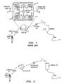
- Low-complexity repeaters Energy efficient small cell base stations are known to be deployed as low-complexity repeaters. Repeaters are also known as relays, repeater stations and relay stations. A low-complexity repeater relies on the processing capability of the target gateway to which the repeater is connected. This is in order to reduce power usage in the repeater to a low level, for example so a small solar panel is sufficient to power the repeater.
- a known repeater 4 includes a mobile communication antenna 8 connected by frequency conversion circuitry 10 to an antenna 12 for electromagnetic radiation of the order of millimetre wavelengths ("mmWave antenna").
- the frequency conversion circuitry 10 includes a frequency-up-conversion branch 14 and a frequency-down-conversion branch 16.
- the frequency-up-conversion branch 14 includes, from the mobile communications antenna 8, a first band pass filter 18 connected to a modulator 20 that is connected to a mmWave signal source 22.
- the modulator 20 is connected to a second band pass filter 24 connected to the mmWave antenna 12.
- the frequency-down-conversion branch 16 includes, from the mmWave antenna 12, a band pass filter 26 connected to a demodulator 28 that is connected to the mmWave signal source 22.
- the demodulator 28 is connected to a further band pass filter 30 connected to the mobile communications antenna 8.
- the information-carrying signal received from the user terminal 2 at a first carrier frequency is frequency- up -converted to a higher carrier frequency which is used to transmit the information to the gateway 6.
- the signal is received, back-converted and decoded.
- data is modulated onto the carrier frequency of the mmWave backhaul link and transmitted to the small cell base station 4.
- the received signal is down-converted to the downlink frequency of the user terminal 2 and transmitted to the user terminal 2.
- the small cell base station 4 acts to up-convert and down-convert signals, but no additional signal processing is performed, in particular no digital signal processing.
- a signalling channel between the small cell base station and gateway needs to be established.
- This signalling channel is required for functions like waking-up the small cell base station or powering-down the small cell base station to an inactive, low power usage, state. This is especially important in low-power small cells and self-sustained small cells, as these need to be powered-up only when required and cannot be kept in a high-energy-consuming stand-by mode for long periods.
- a signalling channel is also required for other functions, for example sending system health and performance data, indicating battery status, and sending configuration commands, from the user terminal 2 to the gateway and vice versa.
- the signalling channel between the gateway and user terminal needs to consume little power.
- a known approach is to establish a dedicated signalling channel alongside the main backhaul transport channel. This signalling channel is separated from the main channel in radio frequency, code, logical layer or time.
- An example of the present invention is a method of transmitting information associated with a relay station from the relay station via a signal, the method comprising:
- Some embodiments provide a method for provision of an intra-channel signalling channel for millimetre wave backhaul links.
- Some embodiments provide a control signalling channel between a relay station and a gateway under the constraints of: no additional baseband data processing, very low power consumption, and compatibility with the power-down requirement of the relay station.
- Some embodiments address the challenging uplink direction of control signalling from the remote relay station, which may be a small cell base station, to the gateway, since in this direction the constraints on energy consumption and complexity are more severe. Nevertheless, some embodiments provide for efficient control signalling in the downlink direction.
- Some embodiments provide for relaying an uplink signal from a network user to the serving gateway via an intermediate low-power and low-complexity relay station, whilst sending additional relay-station-specific control information from the relay station to the gateway, without affecting the decoding of the relayed user signal at the gateway.
- Some embodiments provide uplink communication channels from a repeater-type small access point towards a gateway, without having to implement an additional parallel transmitter chain or digital signal processing capability.
- the relay station is a small cell base station.
- the first node is a user terminal and the second node is a gateway.
- the second frequency band is higher than the first frequency band.
- the first frequency band is a band for cellular mobile telecommunications
- the second frequency band is a millimetre wave or microwave frequency band.
- the modulating comprises modulating the information onto the signal at the second frequency band, and the modulated signal is transmitted towards the second node.
- the modulating comprises modulating the information onto the signal at the first frequency band, and the modulated signal is converted to the second frequency band and transmitted towards the second node.
- the modulating comprises modulating the information onto the signal by amplitude modulation.
- the modulating comprises modulating the information onto the signal by modulation by a modulating signal which is generated by frequency up-converting a given digital code sequence.
- the modulating signal may be a wideband analog baseband signal.
- the modulating signal may be such that the signal is received with a similar bit error rate compared to if this modulation did not occur.
- the information comprises status information in respect of the relay station.
- the method further comprises the relay station receiving from the second node and decoding a control message for the relay station modulated onto a data message for transmission to the first node, the data message being frequency-converted by the relay station from the second frequency band to the first frequency band for transmission to the first node.
- the control message was modulated onto the data message by modulation by a modulating signal generated by frequency up-converting a given digital code sequence.
- This modulating signal may be a wideband analog baseband signal.
- a method of sending information comprising the above-mentioned method of transmitting, and the signal being received at the second node and decoded at the second node to obtain both the information and the signal.
- the present invention also relates to a corresponding relay station, a corresponding method of receiving information and a corresponding first node or second node configured to receive information.
- the present invention also relates to a relay station configured to send information associated with the relay station via a signal, in which the signal carries data associated a first node, the signal passing between the relay station and a second node; the relay station being configured to communicate with the first node in a first frequency band which is a band for cellular mobile telecommunications and configured to communicate with the second node in a second frequency band; the relay station comprises a receiver and a convertor, the receiver being configured to receive the signal at one of the first frequency band and the second frequency band and the convertor being configured to convert the signal to the other of the first frequency and second frequency band for transmission; the relay station further comprising a modulator and a transmitter, the modulator being configured to modulate the information onto the signal at the first frequency band or second frequency band, and the transmitter being configured to transmit the modulated signal.
- a network comprising the above-mentioned relay station, in which the first node is a user terminal and the second node is a gateway, the modulated signal being transmitted to the gateway for decoding to provide the information and the signal.
- the present invention also relates to a method of receiving information associated with a relay station from the relay station via a signal, the method comprising:
- the present invention also relates to a first node or second node configured to receive information associated with a relay station via a signal,
- said first node or second node is the second node, and preferably the second node is a gateway and preferably the first node is a user terminal.
- the inventors realised that in the known approaches, irrespective of whether the signalling channel is separated from the main backhaul link by radio frequency, code, logical layer or time, the known approaches require significant data processing down to base band level, for example to embed the signalling data into load data or as a separate signalling channel. This increases power consumption.
- the inventors realised that such methods should be avoided especially where the small cell base station is mainly implemented to act as a repeater, providing a mmWave link but otherwise having no (or very limited) signal processing functionality.
- the inventors realised that methods should be avoided that require the remote end of the mmWave link, for example the user terminal, to perform these signal processing functions at various times, thereby limiting the possibly to power down the user terminal for energy saving purposes.
- the inventors realised that the known approaches were not well suited to use in low-power nodes providing wireless backhaul links.
- the inventors realised that it is possible to embed the signalling information to be transmitted between the small cell base station and the gateway into the mobile communication signal itself. Two possible methods will be described.
- the signalling information may be status or other information in respect of the relay station; for example any of or any combination of: serial number and/or other identifier, neighbour activity list, battery charge level and/ or battery charge rate, past measurements, traffic information for example loading level, and /or other information regarding the status of, or local environment experienced by, the relay station.
- the first method consists in amplitude-modulating the backhaul signal itself and is primarily suitable for signalling uplink to the gateway.
- the second method consists of embedding an additional, preferably wideband signal onto the carried mobile communication signal.
- the second method is suitable for both uplink and downlink communications. Both methods have the advantages that the data carried by the mobile communication signal is not impaired by the added signalling, the quality of the link between the user terminal and gateway is maintained, and only the radio frequency spectrum allocated to the mobile communication signal is made use of. We now describe the two methods in turn in more detail.
- This method is low in power consumption and does not impair the traffic load data being transmitted.
- the amplitude modulation of the signal carrying the traffic load data with the signalling data is performed either by applying an adjustable attenuation or by modulation of the supply voltage of the power amplifier of the transmitter. No extra carrier signal is implemented nor transport channel radio chain, and little extra hardware is required.
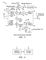
- a user terminal 32 which is a mobile user equipment for cellular wireless telecommunications, is connected via a small cell base station 34 with a gateway 36.
- the small base station 34 may be considered as a repeater or relay.
- the small cell base station 34 includes a mobile communication antenna 38 connected by uplink circuitry 40 to a mmWave antenna 42.
- the mmWave antenna 42 is also connected by downlink circuitry 44 to the mobile communication antenna 38.
- mmWave denotes electromagnetic radiation of the order of millimetre wavelengths.
- the uplink circuitry 40 includes, from the mobile communications antenna 38, a first band pass filter 46 connected to a modulator 48 for frequency up-conversion that is connected to a mmWave signal source 50.
- the modulator 50 is connected via an adjustable attenuator 52 and voltage control amplifier 54 to a second band pass filter 56 connected to the mmWave antenna 42.
- the adjustable attenuator 52 and voltage control amplifier 54 are both connected to a microprocessor 58 which acts to modulate the amplitude of the signal passing through either by attenuation or by amplification control.
- the downlink circuitry 44 includes, from the mmWave antenna 42, a band pass filter 60 connected to a low noise amplifier 62 connected to a demodulator 64 for frequency down-conversion that is connected to the mmWave signal source 50.
- the demodulator 64 is connected to a further band pass filter 66 connected to the mobile communications antenna 38.
- a sample coupler 68 connected via a low pass filter 70 to an envelope detector 72.
- a low frequency modulation is applied to the data carrier channel so as the embed signalling information into the carrier channel itself.
- the total channel power is modulated by the order of 1 dB.
- This amplitude modulation is performed, in one mode by digitally adjusting the attenuation of adjustable attenuator 51, or in another mode by controlling the gain of the power amplifier 52. In both cases, this provides a binary (on/off) amplitude modulation of the signal for transmission via the mmWave antenna 42 to the gateway 36.
- a low modulation frequency of several tens or hundreds of kiloHertz is applied.
- this low frequency modulation a signalling data rate in the order of several tens to hundreds of kilobits per second is available. This is enough bandwidth to transport simple data as to status and performance from the small cell base station 34 to the gateway 36.
- the gateway 36 As the gateway 36 knows the level of amplitude modulation, the modulation frequency and error correction information, the signal carrying the main channel data before modulation is retrieved from the modulated carrier. Also, retrieval of the embedded signalling data from the modulated carrier is undertaken by the gateway 36 in the digital domain, using standard digital down-conversion, digital filtering and error-correction processes.
- Link margin is the difference between a receiver's sensitivity (i.e. the received power at which the receiver will stop working) and the actual/expected received power.
- uplink channel quality indicators are derived from the downlink channel quality measured at user terminals and so no closed automatic gain control loop is applied.
- the downlink signal is sampled by the sample coupler 68.
- the sampling of the downlink signal is done before frequency down-conversion by multiplexer 64.
- the sampling is done after frequency down-conversion by the multiplexer.
- the sampled signal from the sample coupler 68 is filtered by the low pass filter 70, demodulated in the simple envelope detector 72, and is afterwards decoded in a decoder (not shown).
- the microprocessor is the controller of the amplitude modulation/ demodulation processes and is provided in the small cell base station for various other control functions also.
- a large power budget is allocated to compensate for fading due to rain, fog, foliage etc. A part of this power budget is used to provide the amplitude modulation of the carrier signal in order to provide the signalling link between the gateway 36 and the user terminal 2.
- the relayed signal is received at the gateway (step a), the amplitude modulation is reversed (step b) and the actual user signal is then decoded (step c).
- the amplitude modulation reversal is required in this example as the absolute value of the user signal amplitude is measured, specifically for path loss estimation and absolute power control purposes.
- the amplitude modulation does not affect relative comparisons of sub-signals, for example relative comparisons of sounding reference signals for scheduling purposes.
- the amplitude modulation reversal is by removal of the variations in the amplification gain.
- This is straight-forward since the gain variation occurs in integer multiples of the period of the small cell base station's added signalling data. That period is a fixed system constant.
- no significant relative mobility between the small cell base station 34 and the gateway 36 is expected due to their static deployment at fixed locations and their typically line-of-sight transmission mode. At most minor vibrations due to wind or automotive traffic may be expected.
- no significant fading in other words no natural drops in amplitude, obscure the shifts between periods in which the signal is being amplified by the variable amplifier and periods when that signal is not being amplified. In periods when that signal is not being amplified, the original non-amplitude-adjusted signal is being relayed.
- the small cell base station 74 is as shown in Figure 5 .
- a user terminal (not shown) is connected via the small cell base station with a gateway (not shown).
- the small cell base station 74 includes a mobile communication antenna 76 for wireless connection with the user terminal and a mmWave antenna 78 for connection with the gateway.
- a microcontroller 80 generates a fixed digital code sequence 82 which is received at an input 84, up-converted, using a modulator 86 connected to a carrier signal generator 88 to provide a wideband analog baseband signal 90, and then injected into the uplink signal path at a coupler 92.
- the fixed digital code signal is modulated onto the carrier frequency and embedded into the main channel in similar fashion to the amplitude modulation example described above. For completeness, this is now described in detail.
- uplink circuitry 94 includes, from the mobile communications antenna 76, a first band pass filter 96 connected to a modulator 98 for frequency up-conversion that is connected to a mmWave signal source 100.
- the modulator 98 is connected via an adjustable attenuator 102 and voltage control amplifier 104 to a second band pass filter 106 connected to the mmWave antenna 78.
- Downlink circuitry 108 includes, from the mmWave antenna 78, a band pass filter 110 connected to a low noise amplifier 112 connected to a demodulator 114 for frequency down-conversion that is connected to the mmWave signal source 100.
- the demodulator 114 is connected to a further band pass filter 116 connected to the mobile communications antenna 76.
- a sample coupler 118 is connected via a low pass filter 120 to an envelope detector 122.
- the auxiliary data transmission (of signalling data from the small cell base station) is implemented by controlling when the fixed digital code sequence is embedded in the main/primary signal. For example, the absence of the fixed digital code sequence in the signal received from the small cell base station is interpreted at the receiver (gateway or user terminal) as transmission of a digital "0".Conversely, the presence of the fixed digital code sequence corresponds to transmission of a digital "1".
- the fixed digital code sequence is a predefined data sequence multiplied by a given code sequence as known from Code Division Multiple Access (CDMA) systems.
- CDMA Code Division Multiple Access
- the fixed sequence injection approach described with reference to Figure 5 has less interference of the main channel and the possibility of better data rates.
- achievable data rates are limited only by the physical coding and decoding capabilities of the transmitter and receiver (small cell base station and gateway).
- reception (step a') of the signal relayed from a user terminal is followed by decoding (step b') of the signal.
- the process of CDMA-like spreading over a large bandwidth significantly reduces the signal power compared to the primary signal which is of Orthogonal Frequency Division Multiplex (OFDM) type. This reduction is typically to below the noise level of the OFDM signal.
- reception by the gateway in the fixed sequence injection approach as shown in Figure 6 does not have significant effect on the general uplink user signal processing. This is in contrast to reception by the gateway described above in respect of Figure 4 for the amplitude modulation approach where there is a signaificant effect on general uplink user signal processing, namely involving reversal of amplitude modulation.
- program storage devices e.g., digital data storage media, which are machine or computer readable and encode machine-executable or computer-executable programs of instructions, wherein said instructions perform some or all of the steps of said above-described methods.
- the program storage devices may be, e.g., digital memories, magnetic storage media such as a magnetic disks and magnetic tapes, hard drives, or optically readable digital data storage media.
- Some embodiments involve computers programmed to perform said steps of the above-described methods.
Landscapes
- Engineering & Computer Science (AREA)
- Computer Networks & Wireless Communication (AREA)
- Signal Processing (AREA)
- Mobile Radio Communication Systems (AREA)
- Radio Relay Systems (AREA)
Priority Applications (1)
| Application Number | Priority Date | Filing Date | Title |
|---|---|---|---|
| EP14290213.9A EP2978143B1 (fr) | 2014-07-22 | 2014-07-22 | Procédé de transmission d'informations, procédé de réception d'informations, et station de relais |
Applications Claiming Priority (1)
| Application Number | Priority Date | Filing Date | Title |
|---|---|---|---|
| EP14290213.9A EP2978143B1 (fr) | 2014-07-22 | 2014-07-22 | Procédé de transmission d'informations, procédé de réception d'informations, et station de relais |
Publications (2)
| Publication Number | Publication Date |
|---|---|
| EP2978143A1 true EP2978143A1 (fr) | 2016-01-27 |
| EP2978143B1 EP2978143B1 (fr) | 2020-04-22 |
Family
ID=51300676
Family Applications (1)
| Application Number | Title | Priority Date | Filing Date |
|---|---|---|---|
| EP14290213.9A Active EP2978143B1 (fr) | 2014-07-22 | 2014-07-22 | Procédé de transmission d'informations, procédé de réception d'informations, et station de relais |
Country Status (1)
| Country | Link |
|---|---|
| EP (1) | EP2978143B1 (fr) |
Cited By (1)
| Publication number | Priority date | Publication date | Assignee | Title |
|---|---|---|---|---|
| CN115941413A (zh) * | 2022-10-19 | 2023-04-07 | 西安空间无线电技术研究所 | 一种高功率通导融合导航信号生成与接收方法 |
Citations (2)
| Publication number | Priority date | Publication date | Assignee | Title |
|---|---|---|---|---|
| US3028489A (en) * | 1959-12-28 | 1962-04-03 | Bell Telephone Labor Inc | Broadband radio relay system in which signals from adjacent repeaters are compared to control gain of each repeater |
| US4198600A (en) * | 1977-05-31 | 1980-04-15 | Fujitsu Limited | Demodulating system for auxiliary channel in straight-through radio frequency repeater |
Family Cites Families (2)
| Publication number | Priority date | Publication date | Assignee | Title |
|---|---|---|---|---|
| DE68924615T2 (de) * | 1988-05-28 | 1996-05-30 | Nippon Electric Co | Überwachungssystem für Funkkommunikationsapparate. |
| WO2010034341A1 (fr) * | 2008-09-24 | 2010-04-01 | Telefonaktiebolaget L M Ericsson (Publ) | Procédé et mécanisme de commande d’un répéteur dans un système de communication sans fil |
-
2014
- 2014-07-22 EP EP14290213.9A patent/EP2978143B1/fr active Active
Patent Citations (2)
| Publication number | Priority date | Publication date | Assignee | Title |
|---|---|---|---|---|
| US3028489A (en) * | 1959-12-28 | 1962-04-03 | Bell Telephone Labor Inc | Broadband radio relay system in which signals from adjacent repeaters are compared to control gain of each repeater |
| US4198600A (en) * | 1977-05-31 | 1980-04-15 | Fujitsu Limited | Demodulating system for auxiliary channel in straight-through radio frequency repeater |
Cited By (2)
| Publication number | Priority date | Publication date | Assignee | Title |
|---|---|---|---|---|
| CN115941413A (zh) * | 2022-10-19 | 2023-04-07 | 西安空间无线电技术研究所 | 一种高功率通导融合导航信号生成与接收方法 |
| CN115941413B (zh) * | 2022-10-19 | 2024-03-26 | 西安空间无线电技术研究所 | 一种高功率通导融合导航信号生成与接收方法 |
Also Published As
| Publication number | Publication date |
|---|---|
| EP2978143B1 (fr) | 2020-04-22 |
Similar Documents
| Publication | Publication Date | Title |
|---|---|---|
| EP2011360B1 (fr) | Procédé destiné à maîtriser les effets d'interférences externes à la cellule dans un système cellulaire sans fil par transmission par liaison terrestre de données et de formats décodés | |
| JP2018532354A (ja) | Fdr方式を用いる装置が自己干渉除去を行うための方法 | |
| US20150304867A1 (en) | Backhaul Communication in Wireless Networks | |
| US20250142541A1 (en) | Wireless communication method and device | |
| US9813120B2 (en) | Base station, and method and device for returning signal | |
| US20110053602A1 (en) | Repeater gain control method and apparatus | |
| US12273180B2 (en) | System and method for dual-control signaling for the relay scenarios | |
| US7831200B2 (en) | System and method for identifying the path or devices on the path of a communication signal | |
| WO2024015420A1 (fr) | Gestion initiale de faisceau pour déploiements de répéteur commandés par réseau | |
| EP2978143B1 (fr) | Procédé de transmission d'informations, procédé de réception d'informations, et station de relais | |
| US9936461B2 (en) | Communication device and communication method | |
| US11233586B2 (en) | Providing user equipment feedback via signal forwarding device | |
| Nam et al. | Modified dynamic DF for type-2 UE relays | |
| CN112073118A (zh) | 一种tdd同步开关的传输方法和装置 | |
| Wang et al. | Optimum time resource allocation for TDMA-based differential decode-and-forward cooperative systems: a capacity perspective | |
| KR100283076B1 (ko) | 코드분할다중접속 방식의 원격지 기지국을 운용하는 도너 기지국 | |
| CN104202080A (zh) | 一种60m雷达数据传输设备 | |
| CN120568287B (zh) | 一种物联网信息传输方法、装置、相关设备及系统 | |
| CN111147087B (zh) | 中频备份单元、系统和方法 | |
| Axford | Margin and Availability in Transponded SATCOM | |
| Xu et al. | Performance analysis of serial cooperative communications with decode-and-forward relaying and blind-EGC reception under nakagami fading channels | |
| Dindar et al. | Hybrid Amplify and Forward TV Whitespace Radio Over Free-Space Optics | |
| KR20250059826A (ko) | 무선 통신 시스템에서 오류율에 기반한 ncr의 출력 전력을 제어하기 위한 장치 및 방법 | |
| Dat et al. | Performance of uplink packetized lte-a signal transmission on a cascaded radio-on-radio and radio-over-fiber system | |
| KR20250047930A (ko) | 무선통신 시스템에서 장치의 동작 방법 및 상기 방법을 이용하는 장치 |
Legal Events
| Date | Code | Title | Description |
|---|---|---|---|
| PUAI | Public reference made under article 153(3) epc to a published international application that has entered the european phase |
Free format text: ORIGINAL CODE: 0009012 |
|
| AK | Designated contracting states |
Kind code of ref document: A1 Designated state(s): AL AT BE BG CH CY CZ DE DK EE ES FI FR GB GR HR HU IE IS IT LI LT LU LV MC MK MT NL NO PL PT RO RS SE SI SK SM TR |
|
| AX | Request for extension of the european patent |
Extension state: BA ME |
|
| 17P | Request for examination filed |
Effective date: 20160727 |
|
| RBV | Designated contracting states (corrected) |
Designated state(s): AL AT BE BG CH CY CZ DE DK EE ES FI FR GB GR HR HU IE IS IT LI LT LU LV MC MK MT NL NO PL PT RO RS SE SI SK SM TR |
|
| RAP1 | Party data changed (applicant data changed or rights of an application transferred) |
Owner name: ALCATEL LUCENT |
|
| STAA | Information on the status of an ep patent application or granted ep patent |
Free format text: STATUS: EXAMINATION IS IN PROGRESS |
|
| 17Q | First examination report despatched |
Effective date: 20181213 |
|
| GRAP | Despatch of communication of intention to grant a patent |
Free format text: ORIGINAL CODE: EPIDOSNIGR1 |
|
| STAA | Information on the status of an ep patent application or granted ep patent |
Free format text: STATUS: GRANT OF PATENT IS INTENDED |
|
| INTG | Intention to grant announced |
Effective date: 20191128 |
|
| GRAJ | Information related to disapproval of communication of intention to grant by the applicant or resumption of examination proceedings by the epo deleted |
Free format text: ORIGINAL CODE: EPIDOSDIGR1 |
|
| STAA | Information on the status of an ep patent application or granted ep patent |
Free format text: STATUS: EXAMINATION IS IN PROGRESS |
|
| GRAP | Despatch of communication of intention to grant a patent |
Free format text: ORIGINAL CODE: EPIDOSNIGR1 |
|
| STAA | Information on the status of an ep patent application or granted ep patent |
Free format text: STATUS: GRANT OF PATENT IS INTENDED |
|
| GRAS | Grant fee paid |
Free format text: ORIGINAL CODE: EPIDOSNIGR3 |
|
| GRAA | (expected) grant |
Free format text: ORIGINAL CODE: 0009210 |
|
| STAA | Information on the status of an ep patent application or granted ep patent |
Free format text: STATUS: THE PATENT HAS BEEN GRANTED |
|
| INTG | Intention to grant announced |
Effective date: 20200228 |
|
| AK | Designated contracting states |
Kind code of ref document: B1 Designated state(s): AL AT BE BG CH CY CZ DE DK EE ES FI FR GB GR HR HU IE IS IT LI LT LU LV MC MK MT NL NO PL PT RO RS SE SI SK SM TR |
|
| REG | Reference to a national code |
Ref country code: GB Ref legal event code: FG4D |
|
| REG | Reference to a national code |
Ref country code: CH Ref legal event code: EP |
|
| REG | Reference to a national code |
Ref country code: IE Ref legal event code: FG4D |
|
| REG | Reference to a national code |
Ref country code: DE Ref legal event code: R096 Ref document number: 602014064055 Country of ref document: DE |
|
| REG | Reference to a national code |
Ref country code: AT Ref legal event code: REF Ref document number: 1261510 Country of ref document: AT Kind code of ref document: T Effective date: 20200515 |
|
| REG | Reference to a national code |
Ref country code: LT Ref legal event code: MG4D |
|
| REG | Reference to a national code |
Ref country code: NL Ref legal event code: MP Effective date: 20200422 |
|
| PG25 | Lapsed in a contracting state [announced via postgrant information from national office to epo] |
Ref country code: LT Free format text: LAPSE BECAUSE OF FAILURE TO SUBMIT A TRANSLATION OF THE DESCRIPTION OR TO PAY THE FEE WITHIN THE PRESCRIBED TIME-LIMIT Effective date: 20200422 Ref country code: NL Free format text: LAPSE BECAUSE OF FAILURE TO SUBMIT A TRANSLATION OF THE DESCRIPTION OR TO PAY THE FEE WITHIN THE PRESCRIBED TIME-LIMIT Effective date: 20200422 Ref country code: PT Free format text: LAPSE BECAUSE OF FAILURE TO SUBMIT A TRANSLATION OF THE DESCRIPTION OR TO PAY THE FEE WITHIN THE PRESCRIBED TIME-LIMIT Effective date: 20200824 Ref country code: FI Free format text: LAPSE BECAUSE OF FAILURE TO SUBMIT A TRANSLATION OF THE DESCRIPTION OR TO PAY THE FEE WITHIN THE PRESCRIBED TIME-LIMIT Effective date: 20200422 Ref country code: GR Free format text: LAPSE BECAUSE OF FAILURE TO SUBMIT A TRANSLATION OF THE DESCRIPTION OR TO PAY THE FEE WITHIN THE PRESCRIBED TIME-LIMIT Effective date: 20200723 Ref country code: NO Free format text: LAPSE BECAUSE OF FAILURE TO SUBMIT A TRANSLATION OF THE DESCRIPTION OR TO PAY THE FEE WITHIN THE PRESCRIBED TIME-LIMIT Effective date: 20200722 Ref country code: SE Free format text: LAPSE BECAUSE OF FAILURE TO SUBMIT A TRANSLATION OF THE DESCRIPTION OR TO PAY THE FEE WITHIN THE PRESCRIBED TIME-LIMIT Effective date: 20200422 Ref country code: IS Free format text: LAPSE BECAUSE OF FAILURE TO SUBMIT A TRANSLATION OF THE DESCRIPTION OR TO PAY THE FEE WITHIN THE PRESCRIBED TIME-LIMIT Effective date: 20200822 |
|
| REG | Reference to a national code |
Ref country code: AT Ref legal event code: MK05 Ref document number: 1261510 Country of ref document: AT Kind code of ref document: T Effective date: 20200422 |
|
| PG25 | Lapsed in a contracting state [announced via postgrant information from national office to epo] |
Ref country code: BG Free format text: LAPSE BECAUSE OF FAILURE TO SUBMIT A TRANSLATION OF THE DESCRIPTION OR TO PAY THE FEE WITHIN THE PRESCRIBED TIME-LIMIT Effective date: 20200722 Ref country code: RS Free format text: LAPSE BECAUSE OF FAILURE TO SUBMIT A TRANSLATION OF THE DESCRIPTION OR TO PAY THE FEE WITHIN THE PRESCRIBED TIME-LIMIT Effective date: 20200422 Ref country code: HR Free format text: LAPSE BECAUSE OF FAILURE TO SUBMIT A TRANSLATION OF THE DESCRIPTION OR TO PAY THE FEE WITHIN THE PRESCRIBED TIME-LIMIT Effective date: 20200422 Ref country code: LV Free format text: LAPSE BECAUSE OF FAILURE TO SUBMIT A TRANSLATION OF THE DESCRIPTION OR TO PAY THE FEE WITHIN THE PRESCRIBED TIME-LIMIT Effective date: 20200422 |
|
| PG25 | Lapsed in a contracting state [announced via postgrant information from national office to epo] |
Ref country code: AL Free format text: LAPSE BECAUSE OF FAILURE TO SUBMIT A TRANSLATION OF THE DESCRIPTION OR TO PAY THE FEE WITHIN THE PRESCRIBED TIME-LIMIT Effective date: 20200422 |
|
| REG | Reference to a national code |
Ref country code: DE Ref legal event code: R097 Ref document number: 602014064055 Country of ref document: DE |
|
| PG25 | Lapsed in a contracting state [announced via postgrant information from national office to epo] |
Ref country code: DK Free format text: LAPSE BECAUSE OF FAILURE TO SUBMIT A TRANSLATION OF THE DESCRIPTION OR TO PAY THE FEE WITHIN THE PRESCRIBED TIME-LIMIT Effective date: 20200422 Ref country code: AT Free format text: LAPSE BECAUSE OF FAILURE TO SUBMIT A TRANSLATION OF THE DESCRIPTION OR TO PAY THE FEE WITHIN THE PRESCRIBED TIME-LIMIT Effective date: 20200422 Ref country code: RO Free format text: LAPSE BECAUSE OF FAILURE TO SUBMIT A TRANSLATION OF THE DESCRIPTION OR TO PAY THE FEE WITHIN THE PRESCRIBED TIME-LIMIT Effective date: 20200422 Ref country code: SM Free format text: LAPSE BECAUSE OF FAILURE TO SUBMIT A TRANSLATION OF THE DESCRIPTION OR TO PAY THE FEE WITHIN THE PRESCRIBED TIME-LIMIT Effective date: 20200422 Ref country code: IT Free format text: LAPSE BECAUSE OF FAILURE TO SUBMIT A TRANSLATION OF THE DESCRIPTION OR TO PAY THE FEE WITHIN THE PRESCRIBED TIME-LIMIT Effective date: 20200422 Ref country code: EE Free format text: LAPSE BECAUSE OF FAILURE TO SUBMIT A TRANSLATION OF THE DESCRIPTION OR TO PAY THE FEE WITHIN THE PRESCRIBED TIME-LIMIT Effective date: 20200422 Ref country code: ES Free format text: LAPSE BECAUSE OF FAILURE TO SUBMIT A TRANSLATION OF THE DESCRIPTION OR TO PAY THE FEE WITHIN THE PRESCRIBED TIME-LIMIT Effective date: 20200422 Ref country code: CZ Free format text: LAPSE BECAUSE OF FAILURE TO SUBMIT A TRANSLATION OF THE DESCRIPTION OR TO PAY THE FEE WITHIN THE PRESCRIBED TIME-LIMIT Effective date: 20200422 |
|
| PG25 | Lapsed in a contracting state [announced via postgrant information from national office to epo] |
Ref country code: MC Free format text: LAPSE BECAUSE OF FAILURE TO SUBMIT A TRANSLATION OF THE DESCRIPTION OR TO PAY THE FEE WITHIN THE PRESCRIBED TIME-LIMIT Effective date: 20200422 Ref country code: PL Free format text: LAPSE BECAUSE OF FAILURE TO SUBMIT A TRANSLATION OF THE DESCRIPTION OR TO PAY THE FEE WITHIN THE PRESCRIBED TIME-LIMIT Effective date: 20200422 Ref country code: SK Free format text: LAPSE BECAUSE OF FAILURE TO SUBMIT A TRANSLATION OF THE DESCRIPTION OR TO PAY THE FEE WITHIN THE PRESCRIBED TIME-LIMIT Effective date: 20200422 |
|
| PLBE | No opposition filed within time limit |
Free format text: ORIGINAL CODE: 0009261 |
|
| REG | Reference to a national code |
Ref country code: CH Ref legal event code: PL |
|
| STAA | Information on the status of an ep patent application or granted ep patent |
Free format text: STATUS: NO OPPOSITION FILED WITHIN TIME LIMIT |
|
| 26N | No opposition filed |
Effective date: 20210125 |
|
| REG | Reference to a national code |
Ref country code: BE Ref legal event code: MM Effective date: 20200731 |
|
| PG25 | Lapsed in a contracting state [announced via postgrant information from national office to epo] |
Ref country code: LU Free format text: LAPSE BECAUSE OF NON-PAYMENT OF DUE FEES Effective date: 20200722 Ref country code: CH Free format text: LAPSE BECAUSE OF NON-PAYMENT OF DUE FEES Effective date: 20200731 Ref country code: LI Free format text: LAPSE BECAUSE OF NON-PAYMENT OF DUE FEES Effective date: 20200731 |
|
| PG25 | Lapsed in a contracting state [announced via postgrant information from national office to epo] |
Ref country code: BE Free format text: LAPSE BECAUSE OF NON-PAYMENT OF DUE FEES Effective date: 20200731 Ref country code: SI Free format text: LAPSE BECAUSE OF FAILURE TO SUBMIT A TRANSLATION OF THE DESCRIPTION OR TO PAY THE FEE WITHIN THE PRESCRIBED TIME-LIMIT Effective date: 20200422 |
|
| PGFP | Annual fee paid to national office [announced via postgrant information from national office to epo] |
Ref country code: FR Payment date: 20210611 Year of fee payment: 8 |
|
| PG25 | Lapsed in a contracting state [announced via postgrant information from national office to epo] |
Ref country code: IE Free format text: LAPSE BECAUSE OF NON-PAYMENT OF DUE FEES Effective date: 20200722 |
|
| PG25 | Lapsed in a contracting state [announced via postgrant information from national office to epo] |
Ref country code: TR Free format text: LAPSE BECAUSE OF FAILURE TO SUBMIT A TRANSLATION OF THE DESCRIPTION OR TO PAY THE FEE WITHIN THE PRESCRIBED TIME-LIMIT Effective date: 20200422 Ref country code: MT Free format text: LAPSE BECAUSE OF FAILURE TO SUBMIT A TRANSLATION OF THE DESCRIPTION OR TO PAY THE FEE WITHIN THE PRESCRIBED TIME-LIMIT Effective date: 20200422 Ref country code: CY Free format text: LAPSE BECAUSE OF FAILURE TO SUBMIT A TRANSLATION OF THE DESCRIPTION OR TO PAY THE FEE WITHIN THE PRESCRIBED TIME-LIMIT Effective date: 20200422 |
|
| PG25 | Lapsed in a contracting state [announced via postgrant information from national office to epo] |
Ref country code: MK Free format text: LAPSE BECAUSE OF FAILURE TO SUBMIT A TRANSLATION OF THE DESCRIPTION OR TO PAY THE FEE WITHIN THE PRESCRIBED TIME-LIMIT Effective date: 20200422 |
|
| PG25 | Lapsed in a contracting state [announced via postgrant information from national office to epo] |
Ref country code: FR Free format text: LAPSE BECAUSE OF NON-PAYMENT OF DUE FEES Effective date: 20220731 |
|
| PGFP | Annual fee paid to national office [announced via postgrant information from national office to epo] |
Ref country code: GB Payment date: 20230601 Year of fee payment: 10 |
|
| PGFP | Annual fee paid to national office [announced via postgrant information from national office to epo] |
Ref country code: DE Payment date: 20230531 Year of fee payment: 10 |
|
| REG | Reference to a national code |
Ref country code: DE Ref legal event code: R119 Ref document number: 602014064055 Country of ref document: DE |
|
| GBPC | Gb: european patent ceased through non-payment of renewal fee |
Effective date: 20240722 |
|
| PG25 | Lapsed in a contracting state [announced via postgrant information from national office to epo] |
Ref country code: DE Free format text: LAPSE BECAUSE OF NON-PAYMENT OF DUE FEES Effective date: 20250201 |
|
| PG25 | Lapsed in a contracting state [announced via postgrant information from national office to epo] |
Ref country code: GB Free format text: LAPSE BECAUSE OF NON-PAYMENT OF DUE FEES Effective date: 20240722 |