EP2978340B1 - Dispositif de conditionnement et d'application d'un produit cosmétique - Google Patents
Dispositif de conditionnement et d'application d'un produit cosmétique Download PDFInfo
- Publication number
- EP2978340B1 EP2978340B1 EP14718759.5A EP14718759A EP2978340B1 EP 2978340 B1 EP2978340 B1 EP 2978340B1 EP 14718759 A EP14718759 A EP 14718759A EP 2978340 B1 EP2978340 B1 EP 2978340B1
- Authority
- EP
- European Patent Office
- Prior art keywords
- applicator
- perforated support
- elements
- support
- stem
- Prior art date
- Legal status (The legal status is an assumption and is not a legal conclusion. Google has not performed a legal analysis and makes no representation as to the accuracy of the status listed.)
- Not-in-force
Links
Images



Classifications
-
- A—HUMAN NECESSITIES
- A45—HAND OR TRAVELLING ARTICLES
- A45D—HAIRDRESSING OR SHAVING EQUIPMENT; EQUIPMENT FOR COSMETICS OR COSMETIC TREATMENTS, e.g. FOR MANICURING OR PEDICURING
- A45D40/00—Casings or accessories specially adapted for storing or handling solid or pasty toiletry or cosmetic substances, e.g. shaving soaps or lipsticks
- A45D40/26—Appliances specially adapted for applying pasty paint, e.g. using roller, using a ball
- A45D40/262—Appliances specially adapted for applying pasty paint, e.g. using roller, using a ball using a brush or the like
- A45D40/265—Appliances specially adapted for applying pasty paint, e.g. using roller, using a ball using a brush or the like connected to the cap of the container
- A45D40/267—Appliances specially adapted for applying pasty paint, e.g. using roller, using a ball using a brush or the like connected to the cap of the container comprising a wiper
-
- A—HUMAN NECESSITIES
- A46—BRUSHWARE
- A46B—BRUSHES
- A46B1/00—Brush bodies and bristles moulded as a unit
-
- A—HUMAN NECESSITIES
- A46—BRUSHWARE
- A46B—BRUSHES
- A46B3/00—Brushes characterised by the way in which the bristles are fixed or joined in or on the brush body or carrier
- A46B3/005—Bristle carriers and bristles moulded as a unit
-
- A—HUMAN NECESSITIES
- A46—BRUSHWARE
- A46B—BRUSHES
- A46B9/00—Arrangements of the bristles in the brush body
- A46B9/02—Position or arrangement of bristles in relation to surface of the brush body, e.g. inclined, in rows, in groups
- A46B9/021—Position or arrangement of bristles in relation to surface of the brush body, e.g. inclined, in rows, in groups arranged like in cosmetics brushes, e.g. mascara, nail polish, eye shadow
-
- A—HUMAN NECESSITIES
- A46—BRUSHWARE
- A46B—BRUSHES
- A46B2200/00—Brushes characterized by their functions, uses or applications
- A46B2200/10—For human or animal care
- A46B2200/1046—Brush used for applying cosmetics
-
- A—HUMAN NECESSITIES
- A46—BRUSHWARE
- A46B—BRUSHES
- A46B2200/00—Brushes characterized by their functions, uses or applications
- A46B2200/10—For human or animal care
- A46B2200/1046—Brush used for applying cosmetics
- A46B2200/1053—Cosmetics applicator specifically for mascara
-
- A—HUMAN NECESSITIES
- A46—BRUSHWARE
- A46B—BRUSHES
- A46B2200/00—Brushes characterized by their functions, uses or applications
- A46B2200/10—For human or animal care
- A46B2200/1046—Brush used for applying cosmetics
- A46B2200/1053—Cosmetics applicator specifically for mascara
- A46B2200/106—Cosmetics applicator specifically for mascara including comb like element
Definitions
- the present invention relates to an applicator for applying a cosmetic product to the eyelashes and/or eyebrows, and also to a packaging and application device comprising such an applicator and a container containing the product to be applied.
- Application EP 1 507 640 discloses a method for the production of a bristle structure on a carrier by means of a form tool having channels. A forming material forming said bristles is inserted under pressure into the channels, by means of injection moulding.
- Applicator members made at least partially by moulding plastics material are known.
- Application EP 2 332 443 discloses inserting the applicator part between two arms of the support.
- the mechanical connection between the two parts is imperfect and can result in a risk of accidental detachment.
- Application FR 2 890 838 describes an applicator comprising a support formed by a rod which is fixed at one end in a housing of the stem and which comprises at the opposite end a widened head for retaining the applicator part on the rod.
- the applicator part can clear the widened head and detach from the applicator.
- Application EP 1 602 300 describes an applicator member comprising an applicator part that is produced by overmoulding a core carrying a single row of teeth.
- Application EP 1 384 417 discloses an applicator member formed by a rigid body surrounded by a sleeve carrying applicator elements.
- Application US 2005/0034740 describes an applicator wherein the applicator part is overmoulded on a core presenting recesses for a firmer connection between the two components.
- Application WO 2011/152927 discloses an applicator comprising an outer applicator part having a hollow cavity and a moulded inner applicator part that is complementary to said outer part.
- Application US 2005/0034740 describes an applicator wherein the applicator part is overmoulded on a core presenting recesses for a firmer connection between the two components.
- Application EP 2 084 987 describes an applicator comprising a hollow main body carrying bristles on its outer peripheral surface. Applicator elements are moulded by injection through through-bores formed in the wall of the main body.
- Application EP 2 064 968 discloses a brush comprising a reinforced structure having longitudinal ribs running in the longitudinal direction of a rod-shaped support. Longitudinal slots are formed between the ribs with application fingers penetrating the slots, said fingers being supported on opposing sides in their base region by the ribs.
- Application EP 1 752 063 describes an applicator having an oblong main body made of a comparatively hard synthetic material, and a tubular bristle body having bristle-like radially outwardly projecting extensions made of a relatively soft synthetic material.
- the bristle body is axially fixed relative to the main body, the main body having a bead engaging into a corresponding groove of the bristle body.
- Application EP 2 486 822 describes an applicator element consisting of a hollow core element and partly surrounded by a bristle element, both elements being made of materials having different hardness and flexibility.
- an applicator for applying a cosmetic, makeup or care product to the eyelashes and/or eyebrows comprising:
- the material of the applicator part advantageously passes through the perforation or perforations in the support.
- the invention makes it possible for the applicator part to be held in a satisfactory manner after it has been overmoulded on the support, even if thermoplastic materials having very different properties are used to produce the support and the applicator part, without particular adhesion of one to the other.
- connection between the support and the applicator part has increased mechanical strength and there is no risk of the applicator part accidentally detaching, even if the applicator part swells under the effect of a solvent contained in the product.
- the mechanical connection between the perforated support and the applicator part can also be provided away from the application zone, and the user is thus not hampered during application of the product.
- the applicator part is advantageously made of a material having a hardness less than that of the material of which the perforated support is made.
- the applicator elements of the perforated support can thus have different characteristics from those of the applicator part, this being advantageous for making up the eyelashes and/or eyebrows; in one implementation example of the invention, the applicator elements of the support are advantageously designed to load the eyelashes, taking advantage of the fact that they are more rigid and have a greater load of product, and those of the applicator part are designed to separate the eyelashes, since they are more flexible and have a smaller load of product.
- the perforated support stiffens the applicator member, and a very flexible material can be used for the applicator part.
- the applicator part is advantageously made of a thermoplastic material, in particular an elastomer, for example SEBS, a silicone, latex, butyl, EPDM, a nitrile, a thermoplastic elastomer, a polyester elastomer, a polyamide elastomer, a polyethylene elastomer or a vinyl elastomer, a polyolefin such as PE or PP, PVC, EVA, PS, PET, POM, PBT, PA or PMMA. It is possible in particular to use the materials known under the trade names Hytrel®, Cariflex®, Alixine®, Santoprene®, Pebax®, this list not being limiting.
- elastomer for example SEBS, a silicone, latex, butyl, EPDM, a nitrile
- a thermoplastic elastomer for example SEBS, a silicone, latex, butyl, EPDM, a nitrile, a thermo
- the applicator part may be made of a material having a hardness of between 40 Shore A and 80 Shore D, better still between 50 Shore A and 95 Shore A, while the perforated support is made of a material having a hardness greater than that of the material of which the applicator part is made.
- the perforated support is for example made of POM or PP and the applicator part is made of SEBS or Hytrel®.
- the perforated support and the applicator part are advantageously made of materials having different colours, this making it possible to improve the aesthetic appearance and to remind the user of the presence of applicator elements having different properties.
- the applicator part may comprise a head that defines the distal end of the applicator.
- the applicator part preferably extends, at its outer perimeter, around at least one complete circumference along the entire length of the applicator member from said head to the stem.
- the applicator part may comprise a body that carries applicator elements that are formed for example by spikes, in particular having a conical shape, and are preferably oriented radially around the longitudinal axis of the perforated support.
- the applicator elements may have a semi-circular section.
- the applicator elements of the applicator part are preferably not individually injected through the perforated support.
- the body of the applicator part may be thicker than the perforated support and is preferably less wide than the latter.
- the applicator part comprises at least two longitudinally opposite arms that carry the applicator elements.
- the arms of the applicator part may be rectilinear.
- the longitudinal arms of the applicator part are curvilinear, being curved about one or more, convex or concave axes of curvature.
- the arms may be different from one another, one arm being for example rectilinear and another being curvilinear.
- the applicator part after the applicator part has been overmoulded onto the perforated support, the applicator part has at least one material bridge, better still two material bridges, even better still three material bridges, connecting the longitudinal arms together and filling the openings, described below, in the perforated support.
- the applicator part preferably has two opposite main faces that each carry the applicator elements.
- the diameter of the envelope cylinder circumscribed at the free ends of the applicator elements of the applicator part may be between 5 mm and 12 mm, being for example equal to around 9 mm.
- the applicator elements may be disposed on the applicator part in longitudinal rows on the two faces thereof.
- Each face may comprise at least two rows of applicator elements, better still at least three rows, for example four rows.
- the angular offset, on each face, between two consecutive rows of applicator elements may be between 10° and 40°, being for example equal to 30°. This angular offset is measured at the base of the teeth, between the longitudinal mid-planes of the rows.
- the applicator part may or may not comprise applicator elements at its distal end.
- the visible length of the applicator part may be between 10 mm and 35 mm, better still between 20 mm and 26 mm, being for example equal to around 24 mm.
- the body of the applicator part may have a flattened overall shape, wider than thick, the rows of teeth being carried by the main faces of said body.
- the thickness of the body of the applicator part may be between 1 mm and 6 mm, better still between 2.5 mm and 4 mm, being for example equal to around 3 mm.
- the width of the body of the applicator part may be between 1 mm and 7 mm, better still between 3 mm and 5 mm, being for example equal to 4 mm.
- the applicator part may be overmoulded onto the perforated support before the latter is fixed to the stem.
- the perforated support may have a flattened overall shape.
- the perforated support may comprise at least two opposite longitudinal arms, which may be rectilinear.
- the longitudinal arms of the perforated support are curvilinear, being curved about one or more, convex or concave axes of curvature.
- the arms may be different from one another, one arm being for example rectilinear and another being curvilinear.
- the width of the longitudinal arms of the perforated support when the latter is viewed from above perpendicularly to the flattening plane of the support, may be between 1 mm and 7 mm, better still between 1.5 mm and 3 mm, being for example equal to 2 mm.
- the longitudinal arms of the perforated support are preferably connected together by at least one material bridge moulded in one piece with the support.
- the longitudinal arms of the perforated support are advantageously connected together by at least two material bridges, the first material bridge being located for example close to the proximal end of the perforated support and the second material bridge being located for example close to the distal end thereof.
- the perforated support may also comprise a material bridge that connects the longitudinal arms together, approximately half-way between the proximal end and the distal end of the support.
- the material bridge or bridges of the perforated support keep the longitudinal arms of the latter in a fixed manner with respect to one another. Moreover, they improve the mechanical strength of the applicator part.
- the material bridge located half-way between the proximal end and the distal end of the support is completely surrounded by the material of the applicator part, making the support and the applicator part impossible to be mechanically separated after the moulding of the applicator part over the support.
- the material bridge or bridges of the perforated support advantageously have a circular cross section, having a diameter of preferably between 0.9 mm and 3 mm, being for example equal to 1.5 mm.
- the cross section of the material bridge or bridges of the perforated support is not circular, being for example polygonal, in particular rectangular.
- the longitudinal arms advantageously carry the applicator elements of the perforated support, on their opposite sides.
- These applicator elements may have a flattened cross section, with the width at the base thereof preferably corresponding to the width of the arm that carries them.
- the perforated support may comprise a body that has at least one opening.
- the body advantageously carries the applicator elements of the perforated support on two of its opposite sides.
- the applicator part is formed of at least two longitudinal arms, and the opening in the body of the perforated support is intended to be filled with the material of a material bridge of the applicator part.
- the perforated support may comprise a head that defines the distal end of the applicator.
- the body of the perforated support advantageously has two openings, the first being located for example close to the proximal end of the perforated support and the second being located for example close to the distal end thereof.
- the body of the perforated support may also have an opening approximately half-way between its proximal and distal ends.
- the applicator elements of the perforated support are preferably disposed with their flattening plane oriented perpendicularly to the longitudinal axis of the support. This makes it possible, after the applicator member has been wiped, to provide reserves of product on the applicator member, and to define grooves, into which the eyelashes can be introduced, between the applicator elements.
- the width of the applicator elements of the perforated support can decrease progressively towards their free end, such that the latter forms a point, this encouraging the introduction of the eyelashes and/or eyebrows between the applicator elements.
- the length of the applicator elements of the perforated support can decrease progressively in the direction of the distal end of the latter. This makes it easier, when the applicator is dipped into a container containing the product to be applied, for the wiping member of the container to be overcome.
- the diameter of the envelope cylinder circumscribed at the free ends of the applicator elements of the perforated support having a shorter length may be between 3 mm and 14 mm, for example between 4 mm and 6 mm.
- the diameter of the envelope cylinder circumscribed at the free ends of the applicator elements of the perforated support having a longer length may be between 3 mm and 14 mm, for example between 5.5 mm and 7.5 mm.
- the offset between two consecutive applicator elements of the perforated support, measured at their base, between their adjacent flanks, may be between 0.4 mm and 3 mm, being for example equal to 0.6 mm.
- the perforated support may comprise, at its proximal end, a fixing end piece designed to be accommodated in a housing of the stem.
- this end piece When the perforated support is formed by at least two longitudinal arms, this end piece may be internally hollowed out, opening out at least on the side of the applicator part.
- the applicator part may be overmoulded onto the perforated support such that the hollow in the end piece is at least partially filled with the material of the applicator part. The hold of the applicator part on the perforated support is thus reinforced.
- the end piece may be hollowed out along at least half of its length, it being possible for the hollow not to pass through.
- the perforated support comprises a body and the applicator part is formed by at least two longitudinal arms
- the perforated support may comprise an end piece which is covered by the material of the applicator part so as to form a fixing end piece designed to be accommodated in a housing of the stem.
- the perforated support may be formed by a part attached to the stem of the applicator, the end piece being for example clipped into a housing in the stem, and/or the latter being pressed onto the end piece.
- the perforated support preferably has a rectilinear longitudinal axis, but the latter may be curvilinear.
- the visible length of the applicator member may be between 10 mm and 35 mm, better still between 22 mm and 26 mm, being for example equal to around 23.5 mm.
- the stem is preferably connected to a gripping member.
- the stem may be snap-fastened onto a part of this gripping member.
- the stem may have a circular cross section.
- the stem may comprise at least one elastically deformable flexible portion, being able to flex during application and/or when the applicator member is wiped.
- the perforated support may be fixed to the flexible portion of the stem.
- the flexible portion of the stem may comprise a housing, and the perforated support, in particular the fixing end piece of the latter, may be inserted into this housing.
- the flexible portion of the stem may be provided with an annular groove, in order to increase its flexibility.
- a further subject of the invention is a device for packaging and applying a cosmetic, makeup or care, product to the eyelashes and/or eyebrows, comprising an applicator according to the invention, as defined above, and a container containing the product to be applied.
- the gripping member of the applicator may form a cap for closing the container in a sealed manner.
- the container may comprise a member for wiping the applicator.
- the stem may comprise a narrowing which is positioned opposite the wiping member in the closed configuration of the container.
- the packaging and application device 1 shown in Figure 1 comprises a container 2 containing a product P to be applied to the eyelashes and/or eyebrows and an applicator 3 which may be fixed removably to the container 2.
- the applicator 3 comprises a stem 8 of longitudinal axis Y, which is provided at one end with an applicator member 10 and at the other end with a gripping member 9 that likewise forms a cap for closing the container 2 in a sealed manner.
- the latter comprises a body 7 which is provided at the top with a threaded neck 5 onto which the gripping member 9 can be screwed in order to close the container 2 in a sealed manner.
- the applicator 3 can be fixed to the container 2 in some other way.
- the neck 5 may accommodate, as illustrated, a wiping member 6 which is for example inserted into the neck 5.
- This wiping member 6 comprises for example a lip that defines a wiping orifice having a diameter adapted to that of the stem 8.
- the wiping member 6 may be of any type, connected to the container 2 or moulded together therewith.
- the wiping member 6 may also be adjustable.
- the neck 5 of the container 2 may be attached.
- the stem 8 has a rectilinear longitudinal axis Y, but if the stem 8 is not rectilinear, this does not depart from the scope of the present invention.
- the stem 8 may comprise a flexible part at its distal end, optionally provided with an annular groove, the applicator member 10 then being attached to this flexible part.
- the product P is intended to be applied to the eyelashes and/or eyebrows. It may comprise iron oxide, among other pigments, and an aqueous or organic solvent, depending on the formulation.
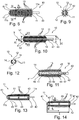
- the applicator member 10 comprises a perforated support 11, visible in Figure 4 , that extends along a longitudinal axis X, which is rectilinear in the example described.
- the perforated support 11 carries applicator elements 12 and comprises, at its proximal end 11 a, a fixing end piece 20 designed to be fixed in a housing of the stem 8.
- the applicator member 10 comprises an applicator part 14 overmoulded onto the perforated support 11 and formed by a body 30 that carries applicator elements 13, which are formed by conical spikes in the example described. These applicator elements 13 are, in this example, oriented radially around the longitudinal axis X of the perforated support 11.
- the applicator part 14 comprises a head 31 that defines the distal end of the applicator 3.
- the applicator part 14 extends, at its outer perimeter, around at least one complete circumference along the entire length of the applicator member 10 from said head 31 to the stem 8.
- the injection point of the material of the applicator part 14 onto the perforated support 11 is located for example at the distal end 11b of the latter.
- the visible length L of the applicator member 10 is preferably between 22 mm and 26 mm.
- the applicator part 14 is preferably made of a material that is more flexible than that of the perforated support 11.
- the applicator part 14 and the perforated support 11 are advantageously produced from materials having different colours.
- the fixing end piece 20 of the perforated support 11 is internally hollowed out, for example along two thirds of its length L o .
- the applicator part 14 is overmoulded onto the perforated support 11 such that the material fills this hollow 21 over a corresponding length L c , in the example described, along around two thirds of the length L o of the end piece 20.
- the length L f of the end piece 20 of the perforated support 11 may be between 5 mm and 10 mm, better still between 6 mm and 9 mm.
- the applicator part 14 has two opposite faces 25 and 26 carrying the applicator elements 13.
- the latter are disposed, in the example described, in four longitudinal rows on each face 25, 26 of the applicator part 14.
- the invention is not limited to a particular number of rows of applicator elements or a particular arrangement of the latter.
- the angular offset ⁇ between two consecutive rows of applicator elements 13 may be between 10° and 40°, being equal to 30° in the example in question.
- the diameter D p of the envelope cylinder circumscribed on the applicator elements 13 of the applicator part 14 may be between 5 mm and 12 mm, being equal to around 9 mm in the example in question.
- the perforated support 11 comprises two opposite longitudinal arms 15 and 16 that are connected together by three material bridges 17, 18, 19, which are visible in Figure 4 .
- the invention is not limited to a particular number of arms and of material bridges of the perforated support.
- the longitudinal arms 15, 16 of the perforated support 11 are rectilinear in the example described and parallel to the axis X.
- the material bridges 17, 18, 19 have a circular cross section in the example in question, having a diameter d s of between 0.9 mm and 3 mm, for example equal to 1.5 mm.
- the third material bridge 19 is located approximately half-way between the proximal end 11a and the distal end 11b of the support 11.
- the length of the applicator elements 12 of the perforated support 11 can decrease progressively in the direction of the distal end 11b of the latter.
- the diameter D s of the envelope cylinder circumscribed at the free ends of the applicator elements 12 of the perforated support 11 having a shorter length may be between 3 mm and 14 mm, better still between 4 mm and 6 mm, being for example equal to 5.4 mm.
- the diameter ⁇ s of the envelope cylinder circumscribed at the free ends of the applicator elements 12 of the perforated support having a longer length may be between 3 mm and 14 mm, for example between 5.5 mm and 7.5 mm, being for example equal to 6.9 mm.
- the applicator elements 12 of the perforated support 11 have a flattened cross section. Their width decreases progressively towards their free end 12a so as to form a point.
- the applicator elements 12 of the perforated support 11 are oriented perpendicularly to the longitudinal axis X.
- the invention is not limited to a particular shape and arrangement of the applicator elements 12.
- the offset e s between two consecutive applicator elements 12 of the perforated support 11, measured at their base, between their adjacent flanks, is between 0.4 mm and 3 mm, being for example equal to 0.6 mm.
- the perforated support 11 has a flattened overall shape.
- the width l s of the longitudinal arms of the perforated support 11 may be between 1 mm and 7 mm, better still between 1.5 mm and 3 mm, being equal to 2 mm in the example in question.
- the length L s of the perforated support 11, not including the end piece 20, may be between 10 mm and 3 mm, better still between 20 mm and 26 mm.
- FIGS 6 and 7 show the applicator part 14 on its own.
- the body 30 of the applicator part 14 is thicker and less wide than the perforated support 11.
- the visible length L p of the applicator part 14 may be between 10 mm and 35 mm, better still between 20 mm and 26 mm.
- the thickness e p of the body 30 of the applicator part 14 may be between 1 mm and 6 mm, better still between 2.5 mm and 4 mm, being equal to 3.1 mm in the example in question.
- the width l p of the body 30 of the applicator part 14 may be between 1 mm and 7 mm, better still between 3 mm and 5 mm, being equal to 4 mm in the example described.
- the applicator part 14 has openings 27, 28, 29, visible in Figure 7 , which correspond to the passage of the material bridges 17, 18 and 19.
- the applicator part 14 is formed by at least two opposite longitudinal arms 45, 46 that carry the applicator elements 13. As shown in Figures 11 , 17 and 18 , the arms 45, 46 of the applicator part 14 are rectilinear in the example described.
- the perforated support 11 then comprises a body 43 that has three openings 47, 48 and 49 in the example in question.
- the first opening 47 in the perforated support 11 is located close to its proximal end 11a and the second opening 48 is located close to its distal end 11b.
- the third opening 49 is located approximately half-way between the proximal and distal ends 11a and 11b of the perforated support 11.
- the openings 47, 48, 49 in the perforated support 11 have a circular section in the example in question.
- the centre of the first opening 47 in the perforated support 11 is located at a distance l 1 from the distal end 11b of the latter, said distance being between 20 mm and 25 mm, being for example equal to 22.47 mm.
- the centre of the second opening 48 in the perforated support 11 is located at a distance l 2 from the distal end 11b of the latter, said distance being between 1.5 mm and 5 mm, being for example equal to 2.47 mm.
- the centre of the third opening 49 in the perforated support 11 is located at a distance l 3 from the distal end 11b of the latter, said distance being between 10 mm and 15 mm, being for example equal to 12.47 mm.
- the body 43 carries the applicator elements 12 of the perforated support 11 on two of its opposite sides 51, 52.
- the perforated support 11 comprises a head 41 that defines the distal end of the applicator 3, the diameter D t of which is between 3 mm and 5 mm, being for example equal to 4 mm.
- the perforated support 11 has a longer length than the applicator part 14.
- the openings 47, 48 and 49 in the body 43 of the perforated support 11 are intended to be filled with the material of the applicator part 14, as is visible in Figure 11 .
- said applicator part 14 After the applicator part 14 has been overmoulded onto the perforated support 11, said applicator part 14 then has three material bridges 57, 58 and 59, visible in Figures 11 , 17 and 18 , which connect the longitudinal arms 45 and 46 of the applicator part 14 together.
- the material bridges 57, 58, 59 have a circular cross section in the example in question, having a diameter d p of between 0.9 mm and 3 mm, for example equal to 1.5 mm.
- the perforated support 11 comprises an end piece 42 covered by the material of the applicator part 14, as is visible in Figures 10 and 11 , so as to form a fixing end piece 40 designed to be accommodated in a housing of the stem 8.
- the perforated support 11 may comprise only two material bridges, for example not comprising the material bridge 19 located half-way between its proximal end 11a and distal end 11b.
- the perforated support 11 comprises a body 43, the latter may have only two openings, for example not comprising the opening 49 located half-way between the proximal end 11a and distal end 11b of the perforated support 11.
- the applicator part 14 may comprise applicator elements on its head 31 that defines the distal end of the applicator 3.
- the applicator elements 12 and 13 may comprise a material that has bacteriostatic properties and/or promotes slip and/or is magnetic.
- the applicator 3 may be subjected to vibrations during use, and/or be heated, that is to say comprise a heating element, and/or be able to rotate. It is also possible for the applicator member 10 to be able to vibrate and to be heated or only to be able to vibrate or only to be heated or only to be able to rotate.
- the gripping member 9 may house an electric motor for rotating the stem.
Landscapes
- Coating Apparatus (AREA)
- Orthopedics, Nursing, And Contraception (AREA)
- Closures For Containers (AREA)
Claims (17)
- Applicateur (3) pour appliquer un produit (P) cosmétique, de maquillage ou de soin, sur les cils et/ou les sourcils comportant :une tige (8), etun organe d'application (10) situé à une extrémité de la tige (8) et comportant :un support ajouré (11) s'étendant le long d'un axe longitudinal (X) et portant des éléments d'application (12), etune partie applicatrice (14) surmoulée sur le support ajouré (11),
l'applicateur étant caractérisé en ce que le support ajouré (11) comprend au moins deux branches longitudinalement opposées (15, 16) et au moins deux ponts de matière (17, 18, 19) raccordant lesdites au moins deux branches ensemble, le premier pont de matière (17) étant situé à proximité de l'extrémité proximale (11a) du support ajouré (11) et le deuxième pont de matière (18) étant situé à proximité de son extrémité distale (11b). - Applicateur selon la revendication précédente, dans lequel la partie applicatrice (14) est réalisée avec un matériau ayant une dureté inférieure à celle du matériau avec lequel le support ajouré (11) est réalisé.
- Applicateur selon l'une quelconque des revendications précédentes, dans lequel le support ajouré (11) et la partie applicatrice (14) sont réalisés avec des matériaux ayant des couleurs différentes.
- Applicateur selon l'une quelconque des revendications précédentes, dans lequel le support ajouré (11) comprend un troisième pont de matière (19).
- Applicateur selon la revendication précédente, dans lequel le troisième pont de matière (19) raccorde les branches longitudinales à mi-chemin entre l'extrémité proximale (11a) et l'extrémité distale (11b) du support ajouré (11).
- Applicateur selon l'une quelconque des revendications précédentes, dans lequel les branches longitudinales (15, 16) du support ajouré (11) sont rectilignes.
- Applicateur selon l'une quelconque des revendications précédentes, dans lequel la partie applicatrice (14) comprend une tête (31) qui définit l'extrémité distale de l'applicateur (3).
- Applicateur selon la revendication précédente, dans lequel la partie applicatrice (14) s'étend, sur son périmètre externe, autour d'au moins une circonférence complète le long de toute la longueur de l'organe d'application (10) de ladite tête (31) à la tige (8).
- Applicateur selon l'une quelconque des revendications précédentes, dans lequel le support ajouré (11) a une forme générale aplatie, la partie applicatrice (14) comportant un corps (30) qui porte les éléments d'application (13), ce corps (30) étant plus épais que le support ajouré (11) et de préférence moins large que ce dernier.
- Applicateur selon l'une quelconque des revendications précédentes, dans lequel le support ajouré (11) comprend à son extrémité proximale (11a), un embout de fixation (20) reçu dans un logement de la tige (8).
- Applicateur selon la revendication précédente, dans lequel l'embout de fixation (20) est évidé intérieurement et au moins partiellement rempli par la matière de la partie applicatrice (14).
- Applicateur selon l'une quelconque des revendications 2, 3 et 6 à 10, dans lequel le support ajouré (11) comporte un corps (43) qui a au moins une ouverture (47, 48, 49), la partie applicatrice (14) étant formé par au moins deux branches longitudinales (45, 46), ladite au moins une ouverture dans le support ajouré (11) étant destinée à être remplie par la matière de la partie applicatrice (14) pour former au moins un pont de matière (57, 58, 59) qui raccorde les branches longitudinales (45, 46) de la partie applicatrice (14) les unes aux autres.
- Applicateur selon l'une quelconque des revendications précédentes, dans lequel le support ajouré (11) porte deux rangées d'éléments d'application (12) disposées à l'opposé l'une de l'autre.
- Applicateur selon l'une quelconque des revendications précédentes, dans lequel les éléments d'application (12) du support ajouré (11) ont une section transversale aplatie.
- Applicateur selon la revendication précédente, dans lequel les éléments d'application (12) du support ajouré (11) sont orientés avec leur plan d'aplatissement perpendiculaire à l'axe longitudinal (X).
- Applicateur selon l'une quelconque des revendications précédentes, dans lequel la partie applicatrice (14) porte des éléments d'application (13) constitués par des picots, notamment de forme conique, qui sont de préférence orientés radialement autour de l'axe longitudinal (X) du support ajouré (11).
- Dispositif (1) de conditionnement et d'application d'un produit (P) cosmétique, de maquillage ou de soin, sur les cils et/ou les sourcils, comportant un applicateur (3) tel que défini dans l'une quelconque des revendications précédentes, et un récipient (2) contenant le produit (P) à appliquer.
Applications Claiming Priority (2)
| Application Number | Priority Date | Filing Date | Title |
|---|---|---|---|
| FR1352917A FR3003737B1 (fr) | 2013-03-29 | 2013-03-29 | Dispositif de conditionnement et d'application d'un produit cosmetique |
| PCT/IB2014/060207 WO2014155328A1 (fr) | 2013-03-29 | 2014-03-27 | Dispositif de conditionnement et d'application d'un produit cosmétique |
Publications (2)
| Publication Number | Publication Date |
|---|---|
| EP2978340A1 EP2978340A1 (fr) | 2016-02-03 |
| EP2978340B1 true EP2978340B1 (fr) | 2018-06-06 |
Family
ID=48613943
Family Applications (1)
| Application Number | Title | Priority Date | Filing Date |
|---|---|---|---|
| EP14718759.5A Not-in-force EP2978340B1 (fr) | 2013-03-29 | 2014-03-27 | Dispositif de conditionnement et d'application d'un produit cosmétique |
Country Status (5)
| Country | Link |
|---|---|
| US (1) | US9955771B2 (fr) |
| EP (1) | EP2978340B1 (fr) |
| CN (1) | CN105072952B (fr) |
| FR (1) | FR3003737B1 (fr) |
| WO (1) | WO2014155328A1 (fr) |
Families Citing this family (5)
| Publication number | Priority date | Publication date | Assignee | Title |
|---|---|---|---|---|
| FR3028152B1 (fr) * | 2014-11-07 | 2018-01-12 | L'oreal | Applicateur d'un produit cosmetique, de maquillage ou de soin, sur les cils et/ou les sourcils |
| FR3039382B1 (fr) * | 2015-07-31 | 2017-08-11 | Montaigu Dev | Dispositif applicateur d'un produit fluide ou pateux sur des fibres keratiniques. |
| US11230464B2 (en) * | 2019-10-17 | 2022-01-25 | Elc Management Llc | Cosmetic dosing system |
| JP2025537420A (ja) | 2022-11-30 | 2025-11-14 | ソシエテ アンデュストリエル ドゥ マティエール プラスティック | 化粧品塗布装置を製造するための方法、化粧品塗布装置、及びこのような塗布装置を備える化粧品吐出デバイス |
| CN118924017A (zh) * | 2023-05-11 | 2024-11-12 | 洽兴包装工业(中国)有限公司 | 涂抹器 |
Citations (5)
| Publication number | Priority date | Publication date | Assignee | Title |
|---|---|---|---|---|
| US6581610B1 (en) * | 1999-07-21 | 2003-06-24 | L'oreal S.A. | Applicator, applicator system, and method for applying a product to the eyelashes |
| EP1507640A2 (fr) * | 2002-05-15 | 2005-02-23 | CORONET-WERKE GmbH | Procede pour la production d'une structure de poils sur un support |
| EP1752063A1 (fr) * | 2005-08-11 | 2007-02-14 | Geka Brush Gmbh | Applicateur, en particulier pour mascara ou des produits cosmétiques similaires |
| EP2064968A2 (fr) * | 2007-11-20 | 2009-06-03 | Beiersdorf AG | Brosse d'application de milieux liquides ou pâteux |
| EP2486822A2 (fr) * | 2011-02-16 | 2012-08-15 | GEKA GmbH | Applicateur doté d'un élément de noyau tubulaire et surmoulé |
Family Cites Families (13)
| Publication number | Priority date | Publication date | Assignee | Title |
|---|---|---|---|---|
| FR2796528B1 (fr) * | 1999-07-21 | 2001-09-21 | Oreal | Dispositif de conditionnement et d'application d'un produit sur les cils ou les sourcils |
| FR2808981B1 (fr) * | 2000-05-19 | 2002-12-13 | Oreal | Applicateur a ame non torsadee |
| DE10102219A1 (de) | 2001-01-19 | 2002-07-25 | Beiersdorf Ag | Applikator für flüssige oder pastöse Medien, insbesondere dekorative kosmetika wie Mascara |
| DE10233341B4 (de) | 2002-07-23 | 2015-02-12 | Geka Gmbh | Sichelförmiger Applikator für flüssige oder pastöse Medien |
| DE102004027098B4 (de) | 2004-06-01 | 2013-10-10 | Geka Gmbh | Applikator für flüssige oder pastöse Medien, insbesondere dekorative Kosmetika wie Mascara |
| FR2890838B1 (fr) | 2005-09-21 | 2007-12-14 | Saint Laurent Parfums | Instrument d'application d'un produit sur les cils ou les sourcils |
| DE202007014474U1 (de) * | 2007-10-16 | 2009-03-05 | Schwan-Stabilo Cosmetics Gmbh & Co. Kg | Aufgespritzte Applikatoren |
| FR2922421B1 (fr) * | 2007-10-23 | 2010-01-29 | Oreal | Applicateur pour peigner ou appliquer un produit sur les cils ou les sourcils |
| PL2084987T3 (pl) | 2008-02-01 | 2013-11-29 | Geka Gmbh | Szczoteczka kosmetyczna ze szczecinami ukształtowanymi na korpusie podstawowym |
| FR2943512B1 (fr) * | 2009-03-27 | 2011-05-27 | Oreal | Applicateur metallique. |
| FR2953379B1 (fr) | 2009-12-08 | 2012-02-10 | Oreal | Applicateur pour appliquer un produit sur les cils et/ou les sourcils |
| WO2011152927A1 (fr) * | 2010-06-04 | 2011-12-08 | Zen Design Solutions Limited | Applicateur de produit cosmétique |
| DE102011056513A1 (de) * | 2011-12-16 | 2013-06-20 | Krauss-Maffei Wegmann Gmbh & Co. Kg | Munitionsdepot |
-
2013
- 2013-03-29 FR FR1352917A patent/FR3003737B1/fr not_active Expired - Fee Related
-
2014
- 2014-03-27 US US14/781,189 patent/US9955771B2/en not_active Expired - Fee Related
- 2014-03-27 CN CN201480018875.2A patent/CN105072952B/zh not_active Expired - Fee Related
- 2014-03-27 WO PCT/IB2014/060207 patent/WO2014155328A1/fr not_active Ceased
- 2014-03-27 EP EP14718759.5A patent/EP2978340B1/fr not_active Not-in-force
Patent Citations (5)
| Publication number | Priority date | Publication date | Assignee | Title |
|---|---|---|---|---|
| US6581610B1 (en) * | 1999-07-21 | 2003-06-24 | L'oreal S.A. | Applicator, applicator system, and method for applying a product to the eyelashes |
| EP1507640A2 (fr) * | 2002-05-15 | 2005-02-23 | CORONET-WERKE GmbH | Procede pour la production d'une structure de poils sur un support |
| EP1752063A1 (fr) * | 2005-08-11 | 2007-02-14 | Geka Brush Gmbh | Applicateur, en particulier pour mascara ou des produits cosmétiques similaires |
| EP2064968A2 (fr) * | 2007-11-20 | 2009-06-03 | Beiersdorf AG | Brosse d'application de milieux liquides ou pâteux |
| EP2486822A2 (fr) * | 2011-02-16 | 2012-08-15 | GEKA GmbH | Applicateur doté d'un élément de noyau tubulaire et surmoulé |
Also Published As
| Publication number | Publication date |
|---|---|
| WO2014155328A1 (fr) | 2014-10-02 |
| US9955771B2 (en) | 2018-05-01 |
| CN105072952A (zh) | 2015-11-18 |
| CN105072952B (zh) | 2017-08-29 |
| FR3003737A1 (fr) | 2014-10-03 |
| EP2978340A1 (fr) | 2016-02-03 |
| US20160051032A1 (en) | 2016-02-25 |
| FR3003737B1 (fr) | 2016-01-08 |
Similar Documents
| Publication | Publication Date | Title |
|---|---|---|
| US10575621B1 (en) | Cosmetic applicator | |
| US8684616B2 (en) | Applicator for applying a composition to the eyelashes and/or the eyebrows | |
| KR101938505B1 (ko) | 2 개의 조립된 부분을 포함하는 도포기 부재 | |
| EP3291701B1 (fr) | Applicateur pour appliquer un produit cosmétique | |
| CN105188472B (zh) | 用于将产品涂抹到睫毛和/或眉毛的涂抹器 | |
| EP2978340B1 (fr) | Dispositif de conditionnement et d'application d'un produit cosmétique | |
| US20170020266A1 (en) | Applicator for applying a cosmetic, makeup or care, product to the eyelashes and/or eyebrows | |
| CN112638200B (zh) | 用于施用产品、特别是化妆品产品的施用器 | |
| US20170251788A1 (en) | Applicator for applying a cosmetic, makeup or care, product to the eyelashes and/or eyebrows | |
| WO2011161584A1 (fr) | Applicateur permettant d'appliquer une composition cosmétique, de maquillage, ou de soins sur les cils ou les sourcils | |
| WO2014174423A1 (fr) | Dispositif d'application d'un produit cosmétique | |
| US10178905B2 (en) | Packaging and application device | |
| CN107105871A (zh) | 将美容、化妆或护理产品涂抹至睫毛和/或眉毛的涂抹器 | |
| CN105813499A (zh) | 用于将美容品、化妆品或护肤品涂抹至睫毛或眼睑的涂抹器 | |
| CN101708085A (zh) | 成品毛刷 | |
| CN107072385B (zh) | 将美容产品、化妆产品或护理产品涂抹至睫毛和/或眉毛的涂抹器 | |
| EP3214971B1 (fr) | Applicateur permettant d'appliquer un produit cosmétique, du maquillage ou un soin sur les cils et/ou les sourcils | |
| US20170354239A1 (en) | Applicator for applying a cosmetic, makeup or care product to the eyelashes and/or eyebrows | |
| EP3541229B1 (fr) | Applicateur pour les cils et/ou les sourcils | |
| HK40033659A (en) | Cosmetic applicator |
Legal Events
| Date | Code | Title | Description |
|---|---|---|---|
| PUAI | Public reference made under article 153(3) epc to a published international application that has entered the european phase |
Free format text: ORIGINAL CODE: 0009012 |
|
| 17P | Request for examination filed |
Effective date: 20151029 |
|
| AK | Designated contracting states |
Kind code of ref document: A1 Designated state(s): AL AT BE BG CH CY CZ DE DK EE ES FI FR GB GR HR HU IE IS IT LI LT LU LV MC MK MT NL NO PL PT RO RS SE SI SK SM TR |
|
| AX | Request for extension of the european patent |
Extension state: BA ME |
|
| RIN1 | Information on inventor provided before grant (corrected) |
Inventor name: CAULIER, ERIC Inventor name: SANCHEZ, MARCEL Inventor name: THENIN, AUDREY Inventor name: ANNONAY, WENDY |
|
| DAX | Request for extension of the european patent (deleted) | ||
| TPAC | Observations filed by third parties |
Free format text: ORIGINAL CODE: EPIDOSNTIPA |
|
| STAA | Information on the status of an ep patent application or granted ep patent |
Free format text: STATUS: EXAMINATION IS IN PROGRESS |
|
| 17Q | First examination report despatched |
Effective date: 20170207 |
|
| GRAP | Despatch of communication of intention to grant a patent |
Free format text: ORIGINAL CODE: EPIDOSNIGR1 |
|
| STAA | Information on the status of an ep patent application or granted ep patent |
Free format text: STATUS: GRANT OF PATENT IS INTENDED |
|
| INTG | Intention to grant announced |
Effective date: 20180116 |
|
| GRAS | Grant fee paid |
Free format text: ORIGINAL CODE: EPIDOSNIGR3 |
|
| GRAA | (expected) grant |
Free format text: ORIGINAL CODE: 0009210 |
|
| STAA | Information on the status of an ep patent application or granted ep patent |
Free format text: STATUS: THE PATENT HAS BEEN GRANTED |
|
| AK | Designated contracting states |
Kind code of ref document: B1 Designated state(s): AL AT BE BG CH CY CZ DE DK EE ES FI FR GB GR HR HU IE IS IT LI LT LU LV MC MK MT NL NO PL PT RO RS SE SI SK SM TR |
|
| REG | Reference to a national code |
Ref country code: GB Ref legal event code: FG4D |
|
| REG | Reference to a national code |
Ref country code: CH Ref legal event code: EP Ref country code: AT Ref legal event code: REF Ref document number: 1005093 Country of ref document: AT Kind code of ref document: T Effective date: 20180615 |
|
| REG | Reference to a national code |
Ref country code: IE Ref legal event code: FG4D |
|
| REG | Reference to a national code |
Ref country code: DE Ref legal event code: R096 Ref document number: 602014026631 Country of ref document: DE |
|
| REG | Reference to a national code |
Ref country code: NL Ref legal event code: MP Effective date: 20180606 |
|
| REG | Reference to a national code |
Ref country code: LT Ref legal event code: MG4D |
|
| PG25 | Lapsed in a contracting state [announced via postgrant information from national office to epo] |
Ref country code: SE Free format text: LAPSE BECAUSE OF FAILURE TO SUBMIT A TRANSLATION OF THE DESCRIPTION OR TO PAY THE FEE WITHIN THE PRESCRIBED TIME-LIMIT Effective date: 20180606 Ref country code: ES Free format text: LAPSE BECAUSE OF FAILURE TO SUBMIT A TRANSLATION OF THE DESCRIPTION OR TO PAY THE FEE WITHIN THE PRESCRIBED TIME-LIMIT Effective date: 20180606 Ref country code: LT Free format text: LAPSE BECAUSE OF FAILURE TO SUBMIT A TRANSLATION OF THE DESCRIPTION OR TO PAY THE FEE WITHIN THE PRESCRIBED TIME-LIMIT Effective date: 20180606 Ref country code: CY Free format text: LAPSE BECAUSE OF FAILURE TO SUBMIT A TRANSLATION OF THE DESCRIPTION OR TO PAY THE FEE WITHIN THE PRESCRIBED TIME-LIMIT Effective date: 20180606 Ref country code: FI Free format text: LAPSE BECAUSE OF FAILURE TO SUBMIT A TRANSLATION OF THE DESCRIPTION OR TO PAY THE FEE WITHIN THE PRESCRIBED TIME-LIMIT Effective date: 20180606 Ref country code: BG Free format text: LAPSE BECAUSE OF FAILURE TO SUBMIT A TRANSLATION OF THE DESCRIPTION OR TO PAY THE FEE WITHIN THE PRESCRIBED TIME-LIMIT Effective date: 20180906 Ref country code: NO Free format text: LAPSE BECAUSE OF FAILURE TO SUBMIT A TRANSLATION OF THE DESCRIPTION OR TO PAY THE FEE WITHIN THE PRESCRIBED TIME-LIMIT Effective date: 20180906 |
|
| PG25 | Lapsed in a contracting state [announced via postgrant information from national office to epo] |
Ref country code: GR Free format text: LAPSE BECAUSE OF FAILURE TO SUBMIT A TRANSLATION OF THE DESCRIPTION OR TO PAY THE FEE WITHIN THE PRESCRIBED TIME-LIMIT Effective date: 20180907 Ref country code: LV Free format text: LAPSE BECAUSE OF FAILURE TO SUBMIT A TRANSLATION OF THE DESCRIPTION OR TO PAY THE FEE WITHIN THE PRESCRIBED TIME-LIMIT Effective date: 20180606 Ref country code: RS Free format text: LAPSE BECAUSE OF FAILURE TO SUBMIT A TRANSLATION OF THE DESCRIPTION OR TO PAY THE FEE WITHIN THE PRESCRIBED TIME-LIMIT Effective date: 20180606 Ref country code: HR Free format text: LAPSE BECAUSE OF FAILURE TO SUBMIT A TRANSLATION OF THE DESCRIPTION OR TO PAY THE FEE WITHIN THE PRESCRIBED TIME-LIMIT Effective date: 20180606 |
|
| REG | Reference to a national code |
Ref country code: AT Ref legal event code: MK05 Ref document number: 1005093 Country of ref document: AT Kind code of ref document: T Effective date: 20180606 |
|
| PG25 | Lapsed in a contracting state [announced via postgrant information from national office to epo] |
Ref country code: NL Free format text: LAPSE BECAUSE OF FAILURE TO SUBMIT A TRANSLATION OF THE DESCRIPTION OR TO PAY THE FEE WITHIN THE PRESCRIBED TIME-LIMIT Effective date: 20180606 |
|
| PG25 | Lapsed in a contracting state [announced via postgrant information from national office to epo] |
Ref country code: CZ Free format text: LAPSE BECAUSE OF FAILURE TO SUBMIT A TRANSLATION OF THE DESCRIPTION OR TO PAY THE FEE WITHIN THE PRESCRIBED TIME-LIMIT Effective date: 20180606 Ref country code: PL Free format text: LAPSE BECAUSE OF FAILURE TO SUBMIT A TRANSLATION OF THE DESCRIPTION OR TO PAY THE FEE WITHIN THE PRESCRIBED TIME-LIMIT Effective date: 20180606 Ref country code: SK Free format text: LAPSE BECAUSE OF FAILURE TO SUBMIT A TRANSLATION OF THE DESCRIPTION OR TO PAY THE FEE WITHIN THE PRESCRIBED TIME-LIMIT Effective date: 20180606 Ref country code: RO Free format text: LAPSE BECAUSE OF FAILURE TO SUBMIT A TRANSLATION OF THE DESCRIPTION OR TO PAY THE FEE WITHIN THE PRESCRIBED TIME-LIMIT Effective date: 20180606 Ref country code: AT Free format text: LAPSE BECAUSE OF FAILURE TO SUBMIT A TRANSLATION OF THE DESCRIPTION OR TO PAY THE FEE WITHIN THE PRESCRIBED TIME-LIMIT Effective date: 20180606 Ref country code: EE Free format text: LAPSE BECAUSE OF FAILURE TO SUBMIT A TRANSLATION OF THE DESCRIPTION OR TO PAY THE FEE WITHIN THE PRESCRIBED TIME-LIMIT Effective date: 20180606 Ref country code: IS Free format text: LAPSE BECAUSE OF FAILURE TO SUBMIT A TRANSLATION OF THE DESCRIPTION OR TO PAY THE FEE WITHIN THE PRESCRIBED TIME-LIMIT Effective date: 20181006 |
|
| PG25 | Lapsed in a contracting state [announced via postgrant information from national office to epo] |
Ref country code: SM Free format text: LAPSE BECAUSE OF FAILURE TO SUBMIT A TRANSLATION OF THE DESCRIPTION OR TO PAY THE FEE WITHIN THE PRESCRIBED TIME-LIMIT Effective date: 20180606 Ref country code: IT Free format text: LAPSE BECAUSE OF FAILURE TO SUBMIT A TRANSLATION OF THE DESCRIPTION OR TO PAY THE FEE WITHIN THE PRESCRIBED TIME-LIMIT Effective date: 20180606 |
|
| REG | Reference to a national code |
Ref country code: DE Ref legal event code: R097 Ref document number: 602014026631 Country of ref document: DE |
|
| PLBE | No opposition filed within time limit |
Free format text: ORIGINAL CODE: 0009261 |
|
| STAA | Information on the status of an ep patent application or granted ep patent |
Free format text: STATUS: NO OPPOSITION FILED WITHIN TIME LIMIT |
|
| 26N | No opposition filed |
Effective date: 20190307 |
|
| PG25 | Lapsed in a contracting state [announced via postgrant information from national office to epo] |
Ref country code: SI Free format text: LAPSE BECAUSE OF FAILURE TO SUBMIT A TRANSLATION OF THE DESCRIPTION OR TO PAY THE FEE WITHIN THE PRESCRIBED TIME-LIMIT Effective date: 20180606 Ref country code: DK Free format text: LAPSE BECAUSE OF FAILURE TO SUBMIT A TRANSLATION OF THE DESCRIPTION OR TO PAY THE FEE WITHIN THE PRESCRIBED TIME-LIMIT Effective date: 20180606 |
|
| REG | Reference to a national code |
Ref country code: DE Ref legal event code: R119 Ref document number: 602014026631 Country of ref document: DE |
|
| PG25 | Lapsed in a contracting state [announced via postgrant information from national office to epo] |
Ref country code: MC Free format text: LAPSE BECAUSE OF FAILURE TO SUBMIT A TRANSLATION OF THE DESCRIPTION OR TO PAY THE FEE WITHIN THE PRESCRIBED TIME-LIMIT Effective date: 20180606 |
|
| REG | Reference to a national code |
Ref country code: CH Ref legal event code: PL |
|
| GBPC | Gb: european patent ceased through non-payment of renewal fee |
Effective date: 20190327 |
|
| PG25 | Lapsed in a contracting state [announced via postgrant information from national office to epo] |
Ref country code: LU Free format text: LAPSE BECAUSE OF NON-PAYMENT OF DUE FEES Effective date: 20190327 Ref country code: AL Free format text: LAPSE BECAUSE OF FAILURE TO SUBMIT A TRANSLATION OF THE DESCRIPTION OR TO PAY THE FEE WITHIN THE PRESCRIBED TIME-LIMIT Effective date: 20180606 |
|
| REG | Reference to a national code |
Ref country code: BE Ref legal event code: MM Effective date: 20190331 |
|
| PG25 | Lapsed in a contracting state [announced via postgrant information from national office to epo] |
Ref country code: IE Free format text: LAPSE BECAUSE OF NON-PAYMENT OF DUE FEES Effective date: 20190327 Ref country code: LI Free format text: LAPSE BECAUSE OF NON-PAYMENT OF DUE FEES Effective date: 20190331 Ref country code: DE Free format text: LAPSE BECAUSE OF NON-PAYMENT OF DUE FEES Effective date: 20191001 Ref country code: CH Free format text: LAPSE BECAUSE OF NON-PAYMENT OF DUE FEES Effective date: 20190331 Ref country code: GB Free format text: LAPSE BECAUSE OF NON-PAYMENT OF DUE FEES Effective date: 20190327 |
|
| PG25 | Lapsed in a contracting state [announced via postgrant information from national office to epo] |
Ref country code: BE Free format text: LAPSE BECAUSE OF NON-PAYMENT OF DUE FEES Effective date: 20190331 Ref country code: FR Free format text: LAPSE BECAUSE OF NON-PAYMENT OF DUE FEES Effective date: 20190331 |
|
| PG25 | Lapsed in a contracting state [announced via postgrant information from national office to epo] |
Ref country code: TR Free format text: LAPSE BECAUSE OF FAILURE TO SUBMIT A TRANSLATION OF THE DESCRIPTION OR TO PAY THE FEE WITHIN THE PRESCRIBED TIME-LIMIT Effective date: 20180606 |
|
| PG25 | Lapsed in a contracting state [announced via postgrant information from national office to epo] |
Ref country code: PT Free format text: LAPSE BECAUSE OF FAILURE TO SUBMIT A TRANSLATION OF THE DESCRIPTION OR TO PAY THE FEE WITHIN THE PRESCRIBED TIME-LIMIT Effective date: 20181008 Ref country code: MT Free format text: LAPSE BECAUSE OF NON-PAYMENT OF DUE FEES Effective date: 20190327 |
|
| PG25 | Lapsed in a contracting state [announced via postgrant information from national office to epo] |
Ref country code: HU Free format text: LAPSE BECAUSE OF FAILURE TO SUBMIT A TRANSLATION OF THE DESCRIPTION OR TO PAY THE FEE WITHIN THE PRESCRIBED TIME-LIMIT; INVALID AB INITIO Effective date: 20140327 |
|
| PG25 | Lapsed in a contracting state [announced via postgrant information from national office to epo] |
Ref country code: MK Free format text: LAPSE BECAUSE OF FAILURE TO SUBMIT A TRANSLATION OF THE DESCRIPTION OR TO PAY THE FEE WITHIN THE PRESCRIBED TIME-LIMIT Effective date: 20180606 |